


Abstract
The main goal of this work is to develop an algorithm for visual presentation of information through light in three-dimensional space. The problem of controlling a large number of digital outputs at the same time using a very small number of control signals is considered. A single-chip microcontroller Arduino Atmega 328 is used as a processor in a control unit (CU). The control unit is implemented based on shift registers. A physical structure of LEDs is also implemented as an executive device (LED matrix). Remote control is done using a Bluetooth module, and software (for controlling the Arduino chip) is added to control the LED matrix. The matrix consists of a total of 125 LEDs, forming a structure of 5 × 5 × 5 LEDs representing a three-dimensional “screen” through which information is presented. The software environment for developing applications specifically for Arduino is used for the software, namely Arduino IDE. The proposed implementation achieves a low-cost 3D display architecture controlled by a voice-controlled volumetric interface. Based on the shift registers used, effective control over the entire 3D visualization system is achieved.
1. Introduction
A light field (LF) is a concept that describes multiple light rays propagating in free space. By combining some of these rays, new views can be generated and three-dimensional (3D) information can be extracted. One of the variants is the stacked 3D LF—a structure obtained by superimposing several 3D LFs, which allows the viewpoint to be freely moved over a wide range. However, the 3D LF is a relatively simple structure and its application is limited due to the insufficient number of vertical light rays. In the paper [1], an effective approach is proposed to estimate the vertical discrepancy between individual 3D LFs in a stacked 3D LF. This discrepancy can serve as key information to overcome the limitation. The main contribution is the definition of a pair of light rays within the stacked 3D LF. The rays in such a pair have a common foreground and background, and the difference between them is only in the vertical. On this basis, an efficient method for image reconstruction for the purpose of mismatch assessment has been developed. The method reconstructs the reference image by connecting all rays that form pairs with rays from the target image in a neighboring 3D SP.
The study [2] presents the development of a low-cost, energy-efficient lighting system in the form of a 3D LED cube (8 × 8 × 8), capable of displaying various patterns, symbols, letters, and numbers with different time delays set according to user selection. The key contribution is the control of a total of 512 LEDs using only three Arduino output (control) pins with a supply voltage below 5 V. The structure is implemented by grouping 64 cathodes into frames and eight anodes into lines, where the combination of eight frames and 64 lines forms the cube.
In [3], an 8 × 8 × 8 LED cube system controlled by the STC89C52RC with the 74HC573 and ULN2803 is proposed. It improves stereoscopic perception compared to 2D LED displays and enables both static and dynamic content suitable for informational and decorative applications.
In paper [4], a visible light communication (VLC) system based on an LED cube display is developed. The system can display content and transmit data simultaneously, with a data rate of around 400 kb/s.
In [5], LFCAVE is presented, an interactive 3D display system built from visualization and interaction modules. In terms of display, a multi-screen light field model is developed, which includes multiple LF displays for users and allows smooth presentations on multiple screens. Compared to traditional single-screen configurations, the system provides a wider viewing angle and allows for observation by a larger number of viewers.
Light field (LF) is a relatively simple concept, as it creates new views by combining pixels from images. 3D LF treats light rays as passing through a line rather than a plane, which makes them easier to capture. In [6], a method for LF rendering in a 3D LF built from 360° images that maintains a maximum field of view is proposed.
The study [7] examines a static volumetric (SV) three-dimensional (3D) active-matrix display (AMD) built on a bus-based architecture with a one-dimensional (1D) connection. This 1D connectivity enables easier implementation by reducing both the physical structure and the electrical interconnections of the 3D display. In the bus-based display system, each light-emitting diode (LED) is activated or deactivated according to the frame rate of the video signal.
In [8], the development of a volumetric display system with a piston-driven moving screen and DMD-based projection of 2D slices is described, where software compensates for optical magnification and a microcontroller synchronizes the processes. The system achieves 12 3D frames per second with 90 layers per frame and about 20 million voxels, with slight flicker observed, but the result remains visually acceptable.
An extensible modular system of LED cubes combined with a game engine for example-based learning has been developed [9]. The modules are implemented as stackable LED cubes using Arduino development boards, and their scalability and inter-module communication are achieved via Bluetooth or WiFi. A communication interface package between the Arduino control module and the game engine is created, enabling content data exchange and real-time interaction.
2. System Implementation
2.1. Implementation of the Three-Dimensional Cube
An LED cube composed of blue diffuse LEDs with dimensions 5 × 5 × 5 is implemented. The implementation of the cube is based on a common cathode type circuit for each of the five layers. Four 74HC595 shift registers are used, which gives up to 32 outputs, with the ULN2803 transistor assembly connected to the first five outputs, which provides enough current for each of the layers. The remaining 25 outputs of the shift registers are connected via resistors in the vertical LED columns. To control the entire LED cube, an Arduino AtMega 328 is used, which provides enough digital inputs and outputs, as well as analog inputs that can be used to control the duration of displaying the image on the cube or to adjust the speed of changing between images. Power is provided by an external power supply with a maximum current of about 3A, which is more than enough for all LEDs to work without worrying about any possible problems. A universal printed circuit board is used for the correct placement of all elements.
2.2. Basic Block Diagram
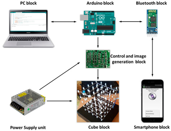
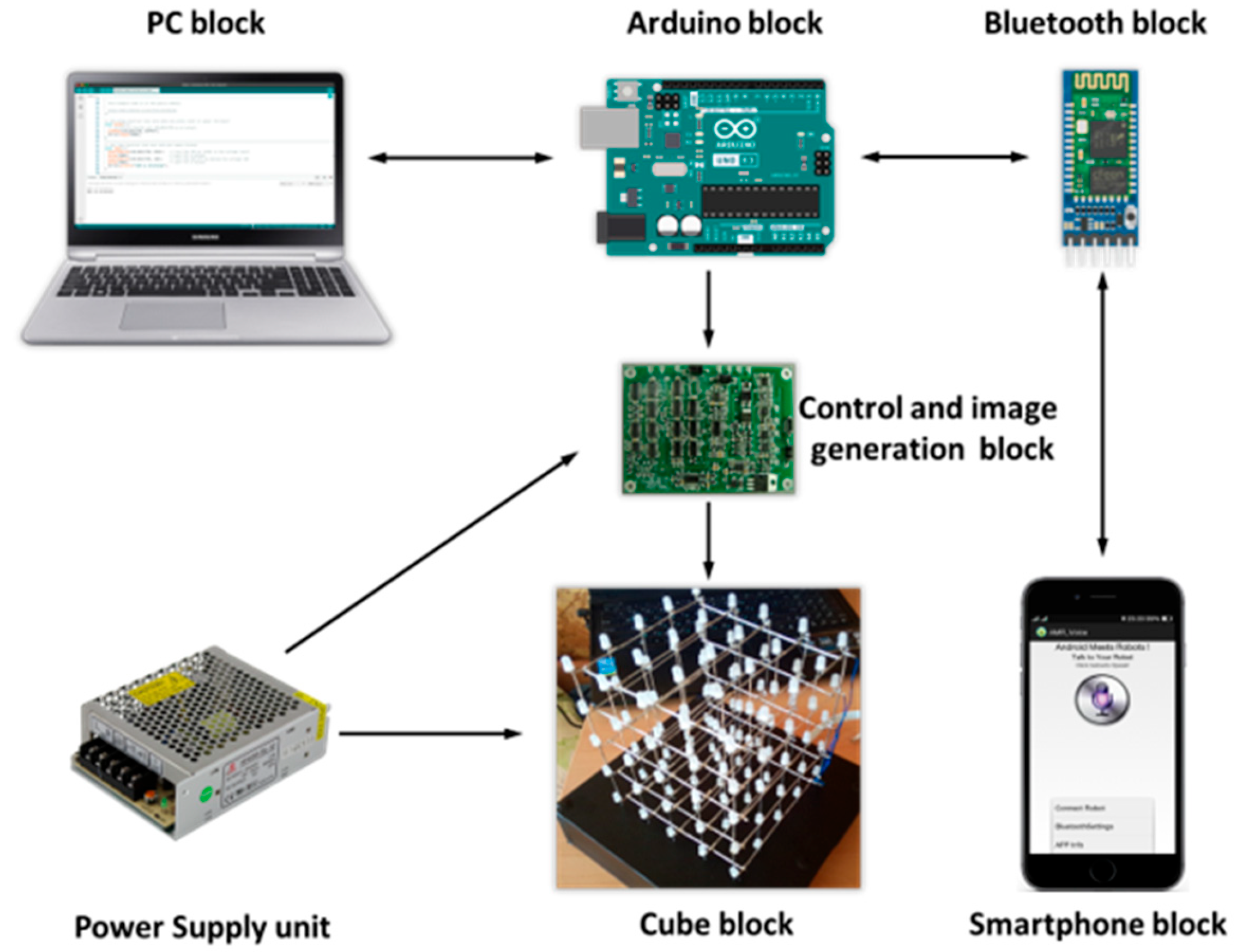
The main modules in the construction of the system are given in Figure 1.
Figure 1.
A block diagram of the system.
- PC block—the computer configuration must have Arduino IDE software, version 2.3 installed.
- Arduino block—in the specific implementation, Arduino AtMega 328 is used, which provides five analog inputs and fourteen digital inputs/outputs, completely sufficient for the needs of the system.
- Power supply unit—When choosing, the operating constant voltage that the power supply unit must provide must be taken into account. In this case, it must be between 5 and 12 volts, and the current must be above 1A for the correct and safe functioning of the entire system. The use of an external power supply unit also provides protection for the USB port of the computer to which the controller is connected.
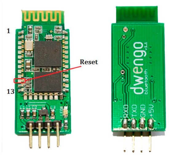
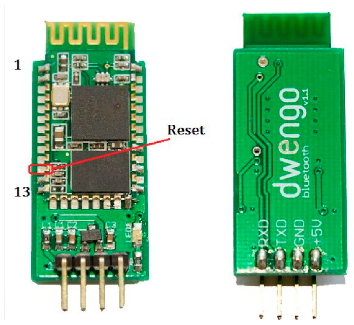
- Bluetooth block—This is an additional module, which is not mandatory, but is used to expand the functionality of the system. It provides the possibility of remote control, such as from a mobile phone. There are a variety of Bluetooth modules, and in practice their application is the same, and they differ only in the maximum data transmission speed and the maximum transmission distance. In practice, the implemented system does not need high indicators of these two characteristics, which is why it is possible to use any available Bluetooth module or purchase the most financially advantageous one. The Bluetooth module can operate at 3.3 volts or at 5 volts, and in this case, it operates at 5 volts.
The JU-MCU module (Figure 2) was used, thanks to which it is possible to remotely change the images that will be visualized on the cube using a smartphone.
Figure 2.
Simple Bluetooth module.
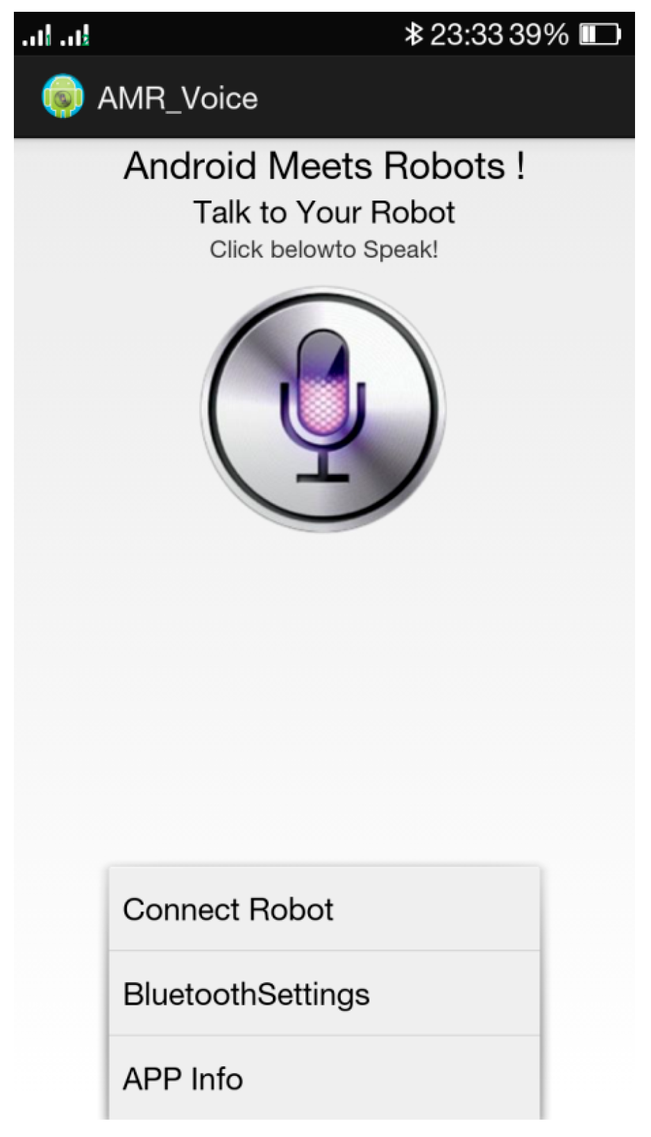
- Smartphone block—Here, all that is needed is a smartphone that is under the control of the Android operating system above version 4.0 and with AMR Voice software version 1.0 installed (Figure 3). This program records the spoken word in real time, converts it into a text string and sends it via Bluetooth to the phone. For proper functioning, it is necessary to connect the phone’s Bluetooth to the system’s Bluetooth beforehand. After establishing the connection, the phone’s program automatically sends the spoken word in the form of a string to the Bluetooth module, and from there it goes to the Arduino microcontroller. There, through it, the images will be remotely changed.
Figure 3.
A view of the AMR Voice smartphone program.
- Control block and image generation—This is perhaps the most essential block in the entire system. Here, the signal coming from the Arduino block is converted into one that is convenient for visualization. This block is a set of four 74HC595 shift registers and a ULN 2803 transistor assembly, which make it possible to obtain 125 different outputs that can control each of the LEDs.
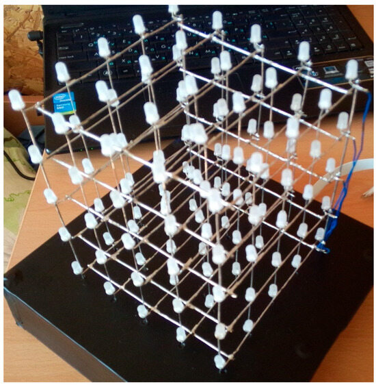
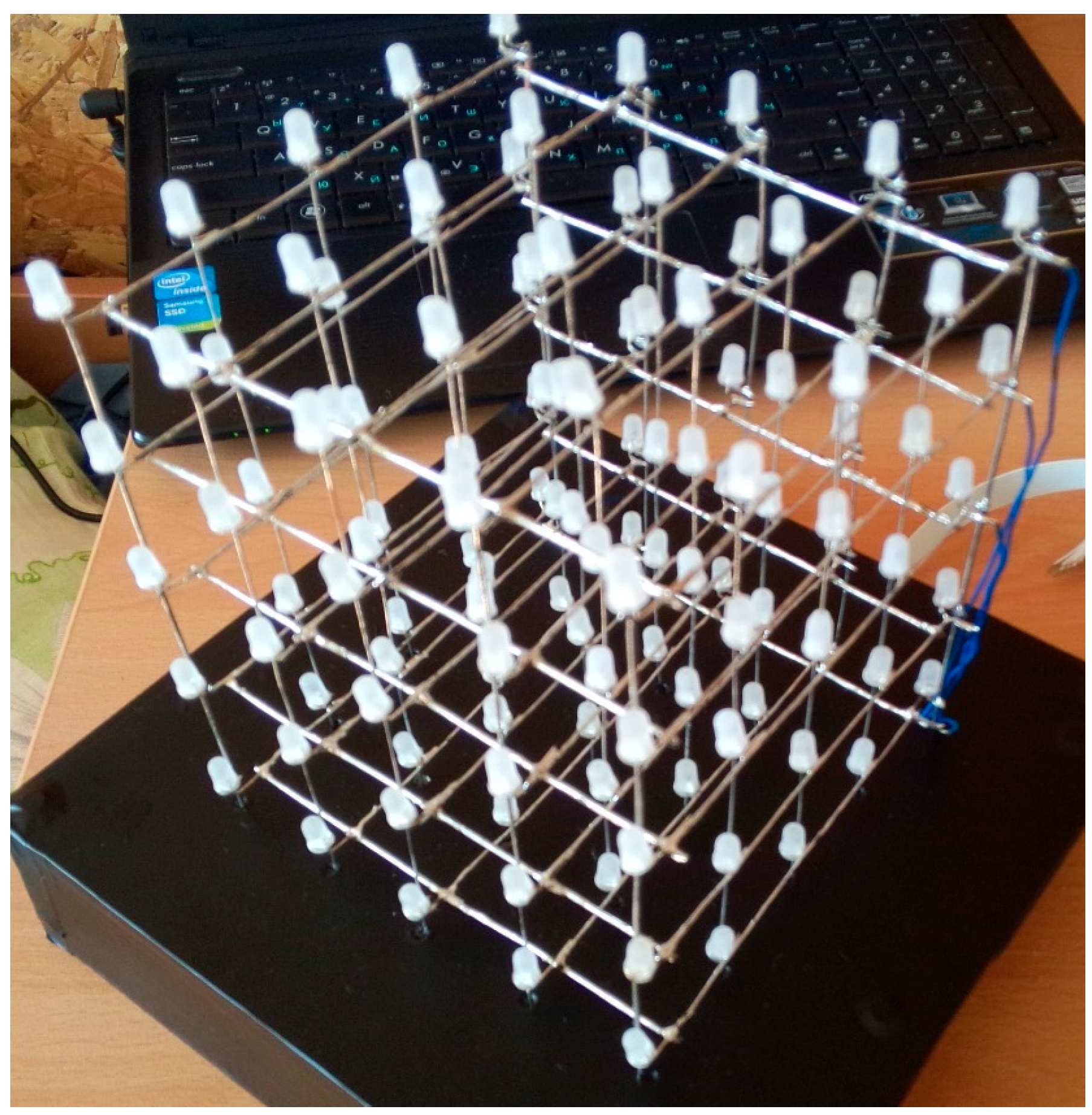
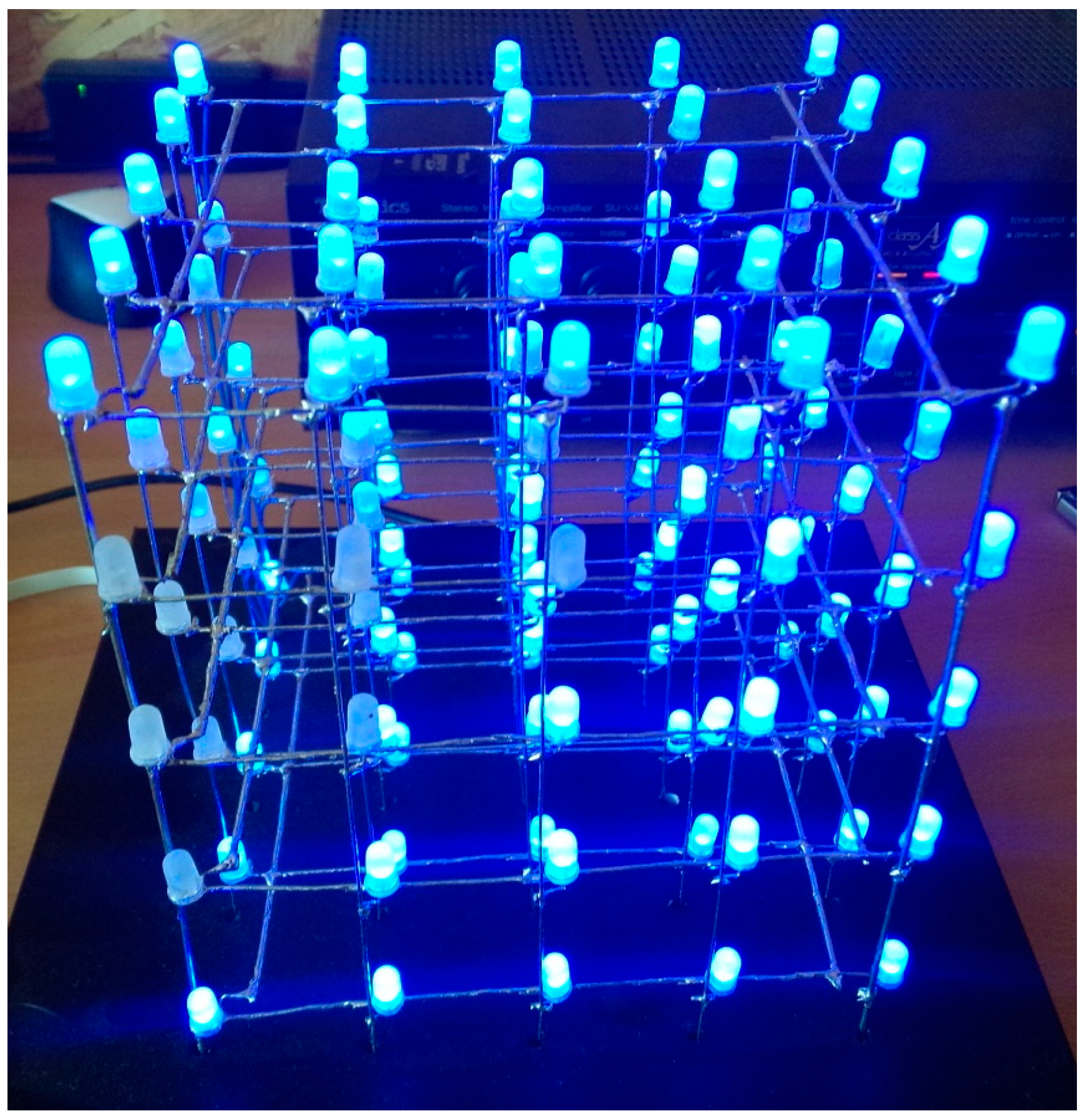
- Cube block—A connection is implemented between 125 blue diffuse LEDs, using an organization in layers and columns (Figure 4). One layer is formed by 25 LEDs connected to a common cathode, and one column is formed by the same number of LEDs from five different layers connected to a common anode. An additional copper wire is used to build the cube, which serves to increase the distance between individual LEDs.
Figure 4.
The construction of the LED cube.
2.3. System Operation
The operation of the LED cube system is associated with the implementation of several basic things:
- Visualization of statically entered images for a certain time and subsequent display of another image. In this mode, the blocks—PC, Arduino, Power supply unit, control unit and image generation—and cube take part. The images to be displayed are loaded from the PC to Arduino, after which the control unit converts the signal so that the observer can perceive the exact image from the LED cube.
- Visualization of a statically entered image with variable speed of movement. The blocks used here are the same as those mentioned above, with the speed change being achieved by a potentiometer placed in the control unit. In this way, the user can change the speed of the animation in real time.
- Visualization of text written in real time. This functionality allows the user to enter any text they want and see it displayed on the LED cube in real time. The input language is English, due to hardware limitations, but there is also the possibility of entering numbers from zero to nine. To obtain the ability to enter text in real time, the serial console in the Arduino IDE development environment is used. Hardware-wise, all blocks from the above block diagram are involved here, except for the Bluetooth block and the smartphone.
- Voice control via smartphone of the statically entered programs. Here, the user is given the opportunity to control the system using their mobile phone. By pronouncing certain words, the user is given the opportunity to change the individual images to be displayed. In order for this functionality to be possible, absolutely all blocks from the block diagram must participate.
3. Experimental Results
3.1. Controlling the Animation Speed
To implement this functionality, it is necessary to additionally include a potentiometer. It is connected to one of the analog inputs provided by the Arduino board. In this way, its reading is read every millisecond and the user is given the opportunity to use the values obtained in real time. The basis of displaying images in the LED cube is based on the speed of displaying and hiding a given image. If this speed is slowed down, a completely different image can be obtained than what was at a faster speed. Programmatically, this speed is adjusted by interrupting the program execution using the delay(ms) function, where ms is the value for which Arduino should interrupt the program. In the case when the speed changes in real time relative to the potentiometer readings, the value taken from the potentiometer simply needs to be set as an argument to delay. This is done by first reading the data coming from the analog input with analogRead(potPin), where potPin is the analog pin to which the potentiometer is connected. The results are the ability to change the speed of movement of a pre-drawn object—in this case a mini cube with dimensions 2 × 2 × 2, which is pre-programmed to move along a certain path. By using the potentiometer, the user is given the opportunity to determine exactly how long this movement should take.
3.2. Displaying Text Entered in Real Time
To obtain this functionality, the serial port is used, through which data is transmitted and received (in this case USB).
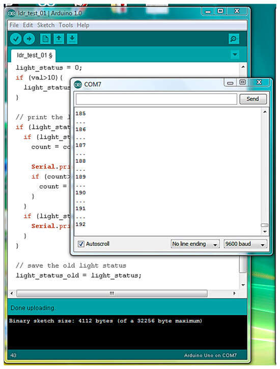
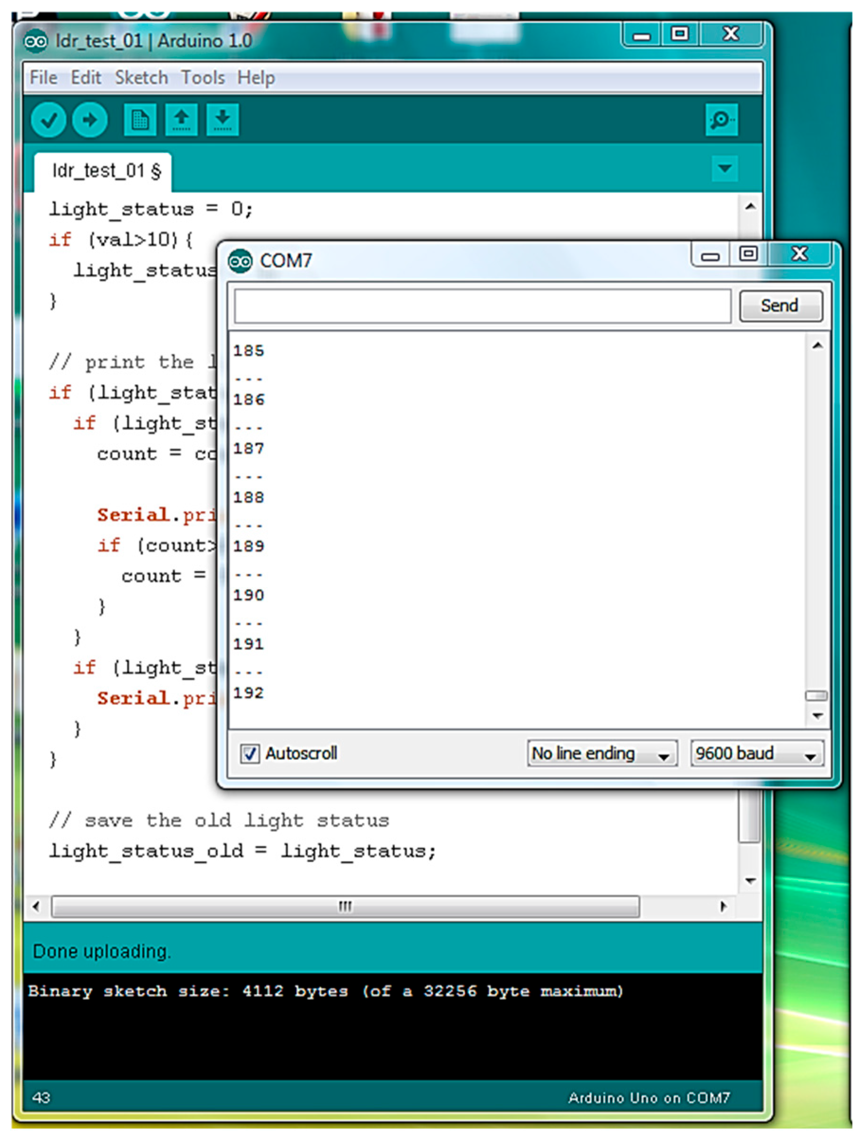
In the program for displaying text that the user enters in real time, it is necessary to have previously entered how each letter is lit (Figure 5). The recognition of the letters themselves is done by ASCII code and separate functions are written based on it, which light up the cube, so that the letters of the Latin alphabet and numbers become readable. As an addition to the initialization of the program, a global variable is added, which stores the value entered by the user.
Figure 5.
Arduino serial monitor.
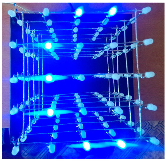
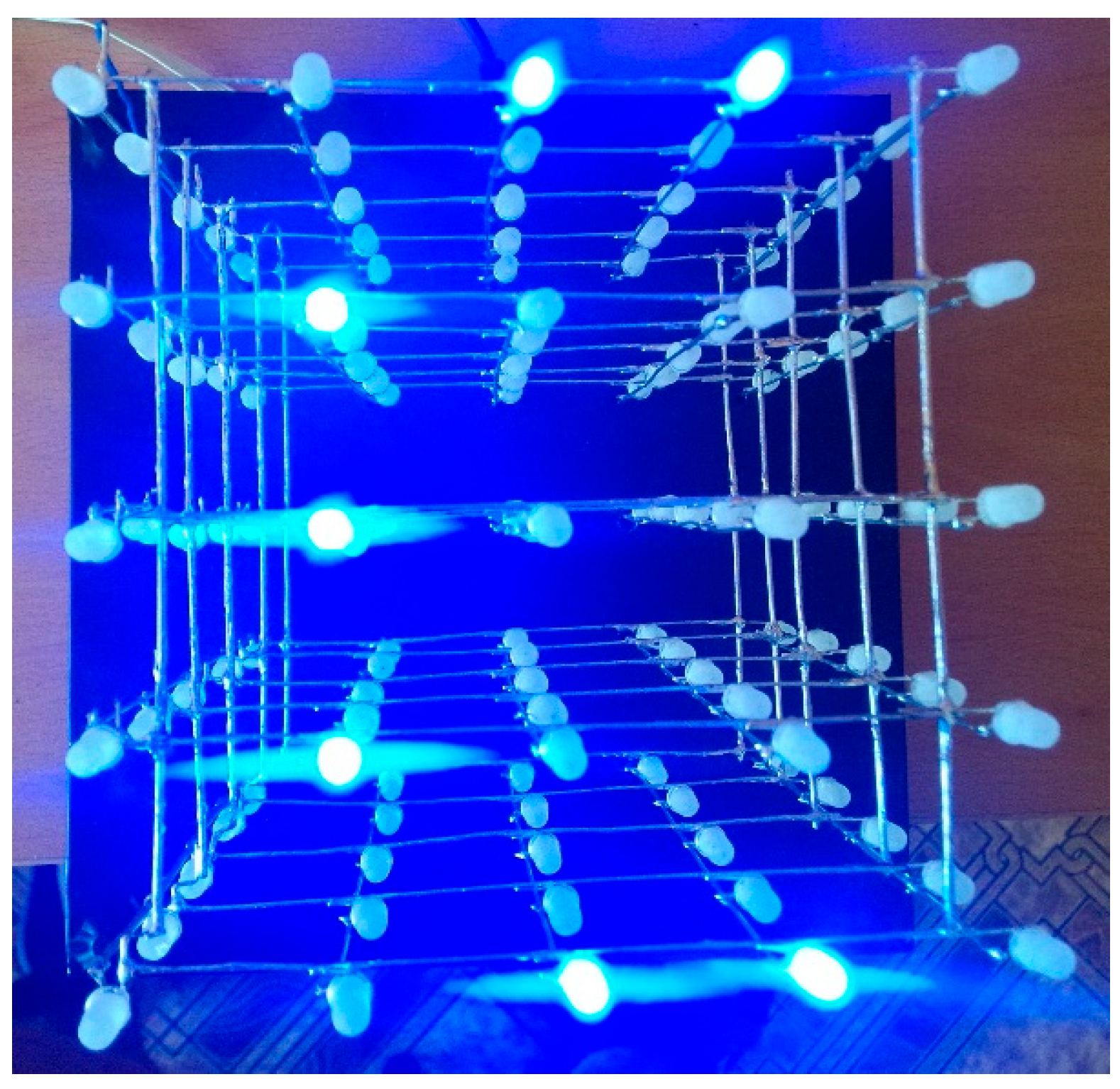
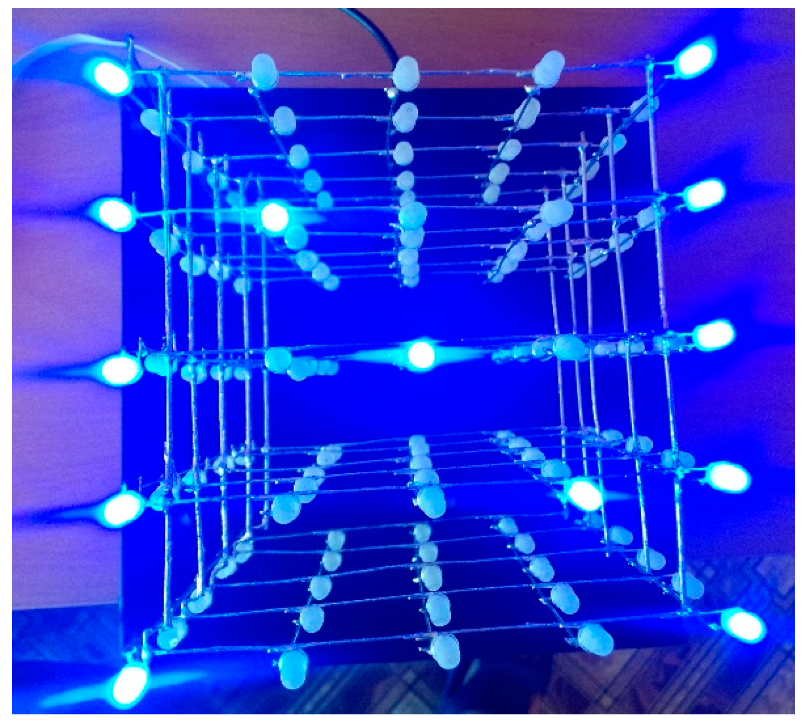
Arduino IDE allows use of the Serial Monitor functionality, through which the user can enter text that reaches Arduino as a sequence of ASCII code. There, in turn, ASCII code recognition and functions that respectively display the correct symbol have been implemented. To increase the effect, an animation has been implemented, with the symbol initially displayed from the bottom and then moving up the layers. If the user enters a word or sentence, the display begins letter by letter, with each letter remaining visible for one second, which is quite enough to understand what has been entered. In addition to Latin letters, it is also possible to display the numbers from 0 to 9, as well as “-”. As an example, you can see the letter C displayed (Figure 6) and then the letter N (Figure 7).
Figure 6.
Depicting the letter “C”.
Figure 7.
Depicting the letter “N”.
3.3. Voice Control of Various Animations Using a Mobile Phone and Bluetooth
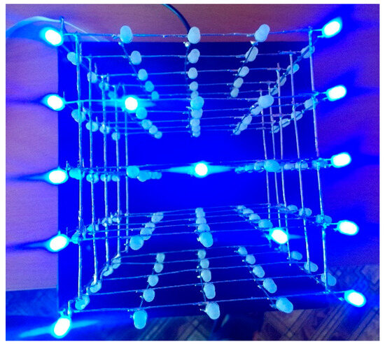
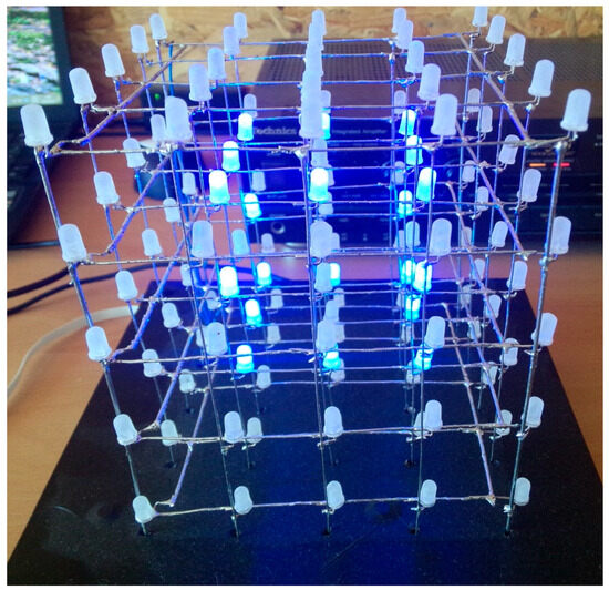
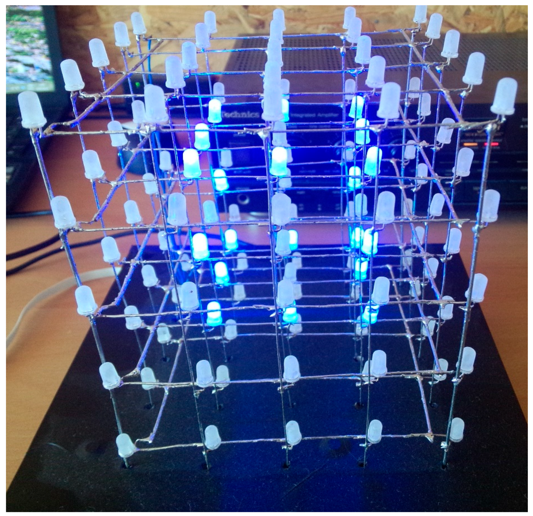
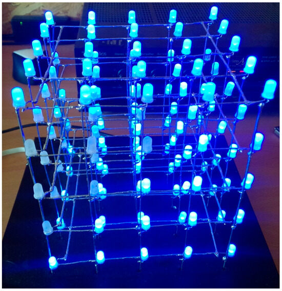
To implement this communication, both sides must be considered. On the mobile phone side, an Android operating system and a program that converts the voice command into a text string, such as AMR_Voice, are required. On the system side, Bluetooth is connected to the pins for sending and receiving information in Arduino. In the program that manages all this, there is a serial receipt of information, this time via Bluetooth. A whole byte of information is read, which is each of the words that the user has spoken in the application. In order to control or, more precisely, change the programs that are being executed, it is necessary to check for a match to the string of words and, accordingly, to start a different function (Figure 8 and Figure 9). The expected result is that when each of the numbers from one to ten is spoken in English, Arduino will start a different program for execution, i.e., a different image.
Figure 8.
Displaying program number 1 from voice control.
Figure 9.
Displaying program number 2 from voice control.
4. Conclusions
In the presented article, a fully functional and working system has been built, which gives the user the opportunity to present information visually and control it remotely in several different ways. The system is implemented in several separate modules. For the implementation of the LED cube itself, blue LEDs with diffuse lighting and a size of 5 mm were selected as the most suitable, on the basis of which the LED matrix with dimensions of 5 × 5 × 5 LEDs (a total of 125 LEDs) was implemented. In the process of making the LED matrix, a decision was made for the distance between the individual LEDs (implementing pixels in the structure) to be 2.5 cm and an auxiliary matrix (layout) was made for the exact positioning and soldering of the individual diodes. The Arduino Atmega 328 microcontroller was chosen to supply the control signals due to its speed of operation, accessibility, and numerous tutorials for working with it on the Internet.
Author Contributions
Conceptualization, G.S., I.B. and A.S.; methodology, G.S., I.B. and A.S.; software, G.S., I.B. and A.S.; validation, G.S., I.B. and A.S.; formal analysis, I.B.; investigation, G.S.; resources, G.S., I.B. and A.S.; data curation, I.B.; writing—original draft preparation, G.S.; writing—review and editing, G.S., I.B. and A.S.; visualization, G.S., I.B. and A.S.; supervision, G.S.; project administration, A.S.; funding acquisition, I.B. All authors have read and agreed to the published version of the manuscript.
Funding
This research received no external funding.
Institutional Review Board Statement
Not applicable.
Informed Consent Statement
Not applicable.
Data Availability Statement
The original contributions presented in this study are included in the article. Further inquiries can be directed to the corresponding author.
Conflicts of Interest
The authors declare no conflicts of interest.
References
- Jung, H.; Lee, H.J.; Rhee, C.E. Disparity Estimation using Light Ray Pair in Stacked 3D Light Field. In Proceedings of the 2022 IEEE 4th International Conference on Artificial Intelligence Circuits and Systems (AICAS), Incheon, Republic of Korea, 13–15 June 2022; pp. 435–438. [Google Scholar] [CrossRef] [Scilit]
- Sri Sai, N.; Subrahmanyam, B.N.; Sai, K.Y.; Sai, A.V.D.S.; Kumar, K.P.; Harsha, S.S.; Sri, U.A.L.S. Efficient design of 8 × 8 × 8 LED Cube with Low Power consumption using Arduino UNO. In Proceedings of the 2020 11th International Conference on Computing, Communication and Networking Technologies (ICCCNT), Kharagpur, India, 1–3 July 2020; pp. 1–6. [Google Scholar] [CrossRef] [Scilit]
- Chen, Q.; Xu, J. Design of 8 × 8 × 8 LED Light Cube System Based on STC89C52RC. In Proceedings of the 2018 2nd IEEE Advanced Information Management, Communicates, Electronic and Automation Control Conference (IMCEC), Xi’an, China, 25–27 May 2018; pp. 2589–2591. [Google Scholar] [CrossRef] [Scilit]
- Li, W.; Zhao, C.; Lv, Z.; Cheng, Z.; Liu, Z. The Study of Visible Light Communication based on LED Array Cube Display. In Proceedings of the 2020 21st International Conference on Electronic Packaging Technology (ICEPT), Guangzhou, China, 12–15 August 2020; pp. 1–4. [Google Scholar] [CrossRef] [Scilit]
- Lu, H.; Shan, W.; Zhang, Y.; Song, L.; Zhang, X.; Ma, S.; Zhang, L.; Gao, W. LFCAVE: Interactive 3D Space with Multiple Light Field Displays. In Proceedings of the 2024 IEEE International Conference on Multimedia and Expo Workshops (ICMEW), Niagara Falls, ON, Canada, 15–19 July 2024; pp. 1–2. [Google Scholar] [CrossRef] [Scilit]
- Frade, J. Three-dimensional space displacement through a fourth spatial dimension explains both light speed value and special relativity. Phys. Essays 2023, 36, 242–249. [Google Scholar] [CrossRef] [Scilit]
- Lin, W.L.; Chung, C.Y. A Bus-Based Static Volumetric Three-Dimensional Active Matrix Display With a One-Dimensional Connection. J. Disp. Technol. 2012, 8, 656–662. [Google Scholar] [CrossRef] [Scilit]
- Yucesoy, V.; Tunaoglu, D.; Kovachev, M.; Ilieva, R.; Onural, L. Design and Implementation of a DMD Based Volumetric 3D Display. In Proceedings of the 2008 3DTV Conference: The True Vision—Capture, Transmission and Display of 3D Video, Istanbul, Turkey, 28–30 May 2008; pp. 29–32. [Google Scholar] [CrossRef] [Scilit]
- Liu, F.J.; Tseng, C.W. Design and Implementation of STEAM Interactive LED-Cube Teaching Aids. In Proceedings of the 2024 IEEE 7th Eurasian Conference on Educational Innovation (ECEI), Bangkok, Thailand, 26–28 January 2024; pp. 132–135. [Google Scholar] [CrossRef] [Scilit]
Disclaimer/Publisher’s Note: The statements, opinions and data contained in all publications are solely those of the individual author(s) and contributor(s) and not of MDPI and/or the editor(s). MDPI and/or the editor(s) disclaim responsibility for any injury to people or property resulting from any ideas, methods, instructions or products referred to in the content. |
© 2026 by the authors. Licensee MDPI, Basel, Switzerland. This article is an open access article distributed under the terms and conditions of the Creative Commons Attribution (CC BY) license.