


Abstract
In recent years, increasing environmental concerns have intensified the demand for lightweight vehicle bodies to improve fuel efficiency. Consequently, aluminum alloys have been increasingly applied to automotive body structures. Resistance spot welding (RSW), which enables high-volume production, is widely used in the automotive industry; however, variability in nugget shape causes fluctuations in nugget diameter, resulting in instability in joint strength. In this study, a hole was introduced on the surface of an aluminum alloy sheet to suppress nugget shape variability. Specifically, a hole with a diameter of 2 mm was machined at the center of the aluminum alloy sheet between the sheet and the electrode. The results showed that the variation in nugget diameter was significantly reduced under the hole condition compared with the condition without a hole. Observations of the joint interface revealed that nugget shape variability was also suppressed under the hole condition. These findings indicate that the introduction of a hole stabilizes nugget formation at the faying interface, thereby reducing variation in nugget diameter.
1. Introduction
In recent years, increasing environmental concerns in the automotive industry have intensified the demand for improved fuel efficiency. To achieve this, reducing vehicle body weight is essential. Therefore, the adoption of lightweight materials, such as aluminum alloys, for automotive body structures has been increasingly promoted. Aluminum alloys have a density approximately one-third that of steel and exhibit high specific strength [1,2,3]. For these reasons, their application is expected to contribute significantly to improved fuel efficiency through vehicle weight reduction. Several joining technologies for aluminum alloys have been developed, including friction drill joining (FDS), friction stir welding, and resistance spot welding (RSW) [4,5,6]. Among these, RSW is widely used in the automotive industry because of its cost efficiency and suitability for mass production. Accordingly, the application of RSW to aluminum alloys has been actively investigated for practical use. However, a major challenge in the resistance spot welding of aluminum alloys is that variation in nugget diameter leads to corresponding fluctuations in joint strength [7,8,9]. Previous studies have indicated that variation in nugget shape is one of the primary factors responsible for this nugget diameter variability. In aluminum alloys, the oxide film formed on the surface is irregularly fractured under electrode pressure, and current flows through these fractured regions. As a result, variation in nugget shape tends to occur from the very beginning of the current application [9,10]. Therefore, to suppress nugget diameter variability, it is important to the control location of oxide film breakdown and stabilize the current path. In this study, it was hypothesized that introducing a hole on the sheet surface would create stress concentration at the hole edge, thereby promoting circular oxide film breakdown between the sheet and the electrode as well as between the sheets. This was expected to produce a more uniform current path, suppress variation in the heat generation location, stabilize nugget formation, and ultimately reduce nugget diameter variability during continuous welding.
2. Materials and Methods
2.1. Materials and Welding Conditions
The test materials were A5052-O aluminum alloy sheets with a thickness of 1.0 mm. Welding was performed using a resistance spot welding system equipped with a direct-current inverter power supply. The electrode geometry was R100 (SMK, Tokyo, Japan) for both the positive and negative electrodes, and the electrodes were made of alumina-dispersion-strengthened copper. The welding conditions are shown in Table 1. The chemical composition of the material is shown in Table 2. Hereafter, the number of welds is designated as N1, N2, …, and N30.
Table 1.
Welding conditions for aluminum alloys.
Table 2.
Chemical composition of A5052-O alloy.
2.2. Methods for Machining Hole Shape
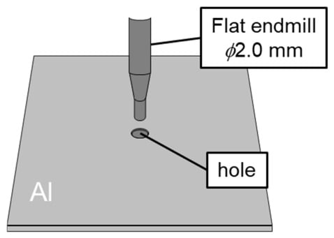
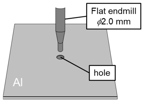
In this study, specimens with a hole at the center of the joint were prepared to investigate the effect of hole geometry on nugget formation in resistance spot welding of aluminum alloys. The machining procedure is shown in Figure 1. As shown in Figure 1, a hole was machined on the aluminum alloy sheet on the positive electrode side using a flat-end mill with a diameter of 2.0 mm. The hole diameter and depth were 2.0 mm and 0.4 mm, respectively. The aluminum alloy sheet with the hole and the sheet without a hole were then assembled and welded.
Figure 1.
Schematic illustration of the hole shape machining process on the sheet surface.
2.3. Macro-Observation Method of the Interface and Measurement
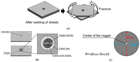
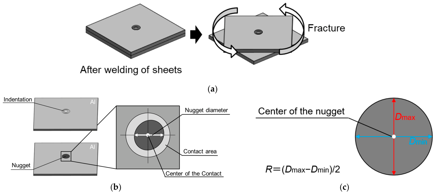
In this study, macro-fracture surface observation was conducted to investigate nugget shape. As shown in Figure 2a, the sheet on the positive electrode side was fixed in a vise, and the welded joint was fractured by applying a manual torsional load in a constant direction. Following the fracture, the nugget diameter on the negative electrode side was quantified by observing the fractured surface using image analysis software (DSX 3.1.8, Olympus, Tokyo, Japan). As shown in Figure 2b, the diameter was determined by measuring the interface passing through the geometric center of the nugget. To evaluate the morphological consistency of the nugget, the roundness was analyzed as an indicator of shape variability. As shown in Figure 2c, the roundness was defined and calculated as half of the difference between the maximum diameter (Dmax) and the minimum diameter (Dmin) passing through the nugget center, using the DSX software’s measurement functions.
Figure 2.
Method for observing the nugget at the faying interface and for measuring the nugget diameter and roundness: (a) schematic illustration of torsional fracture; (b) measurement methods for nugget diameter; (c) measurement methods for nugget roundness.
2.4. Numerical Simulation Conditions
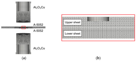
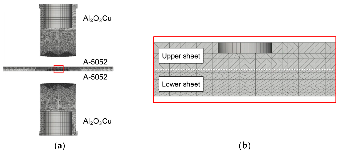
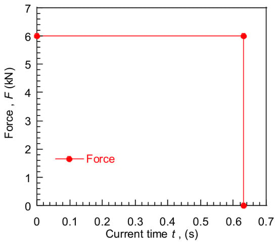
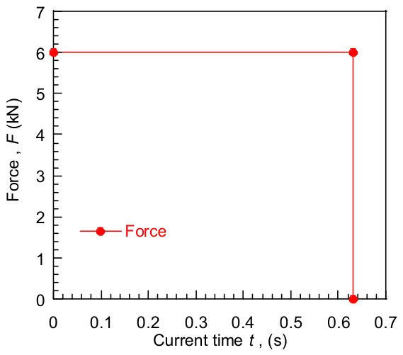
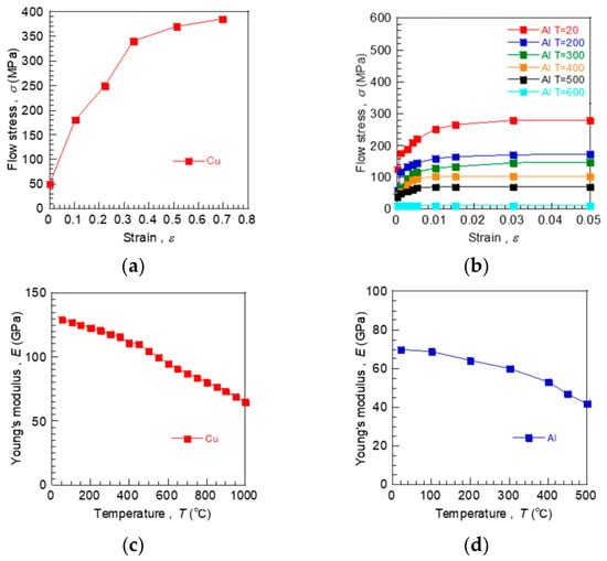
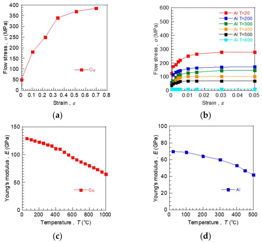
Figure 3a shows the numerical simulation model. The model was constructed as a two-dimensional axisymmetric model, and the material properties of the electrodes and sheets were set to be the same as those used in the experiments. The software used was Simufact Welding 2024.2 (MSC Software, Tokyo, Japan), and the base mesh size was set to 0.2 mm. In addition, the aluminum alloy sheet with a hole on its surface was modeled with a diameter of 2 mm and a depth of 0.4 mm, as shown in Figure 3b. Figure 4 shows the welding conditions used in the numerical simulation, and Figure 5a–d shows the boundary conditions.
Figure 3.
Numerical simulation model: (a) overview of the numerical simulation model; (b) diagram of the sheet surface using hole shape.
Figure 4.
Welding conditions for numerical simulation.
Figure 5.
Boundary conditions for numerical simulation: (a) stress–strain (Cu); (b) stress–strain (Al); (c) Young’s modulus (Cu); (d) Young’s modulus (Al).
3. Results and Discussion
3.1. Results of Macro-Observation of the Interface and Roundness Measurements
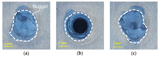
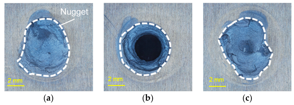
Figure 6 shows the nugget morphologies observed at the joint interface under the condition without a hole on the sheet surface. As shown in Figure 6a–c, the nugget shape varied depending on the weld number under the no-hole condition. In contrast, Figure 7 shows the nugget morphologies observed at the joint interface under the condition with a hole on the sheet surface. As shown in Figure 7a–c, variation in nugget shape was suppressed under the hole condition. Therefore, it was confirmed that by introducing a hole, nugget formation remained stable regardless of the number of welds.
Figure 6.
Observation results of the nugget at the faying interface at a current passage time of 100 ms under the condition without hole shape: (a) results of the first joining process (N1); (b) results of the second joining process (N2); (c) results of the third joining process (N3).
Figure 7.
Observation results of the nugget at the interface at a current passage time of 100 ms under the condition with hole shape: (a) results of the first joining process (N1); (b) results of the second joining process (N2); (c) results of the third joining process (N3).
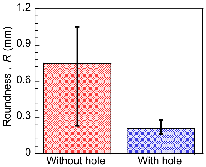
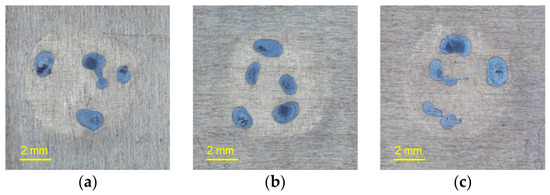
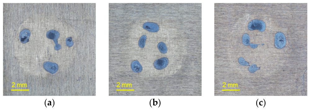
To quantitatively evaluate nugget shape variability, nugget roundness was measured. The results in Figure 8 show that nugget shape variation was reduced under the hole condition. Previous studies have suggested that variation in nugget shape is caused by fluctuations in the heat generation location due to current passing through fractured regions of the oxide film [9,10]. Therefore, Figure 9 and Figure 10 show observations of the nugget at the joining interface at a current application time of 5 ms.
Figure 8.
Measurement results of nugget roundness under both conditions.
Figure 9.
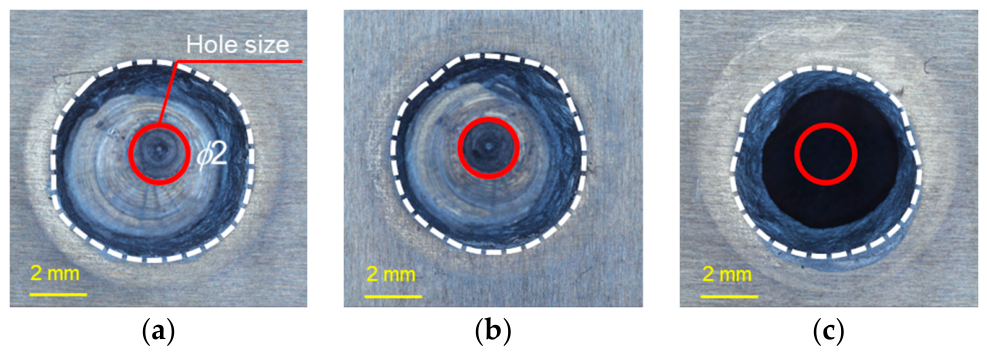
Observation results of the nugget at the interface at a current passage time of 5 ms under the condition without hole shape: (a) results of the first joining process (N1); (b) results of the second joining process (N2); (c) results of the third joining process (N3).
Figure 10.
Observation results of the nugget at the interface at a current passage time of 5 ms under the condition with hole shape: (a) results of the first joining process (N1); (b) results of the second joining process (N2); (c) results of the third joining process (N3).
As shown in Figure 9a–c, under the no-hole condition, the shape of the heat generation region varied depending on the weld number. In contrast, as shown in Figure 10a–c, under the hole condition, variation in the heat generation region was suppressed. These results suggest that the presence of a hole controls the current path by localizing stress concentration at the hole edge, thereby promoting oxide film breakdown preferentially at that location.
3.2. Numerical Simulation Results of the Equivalent Stress Distribution and the Stress Distributions in the X and Z Directions Under Electrode Force
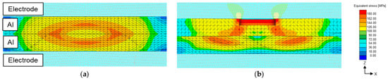
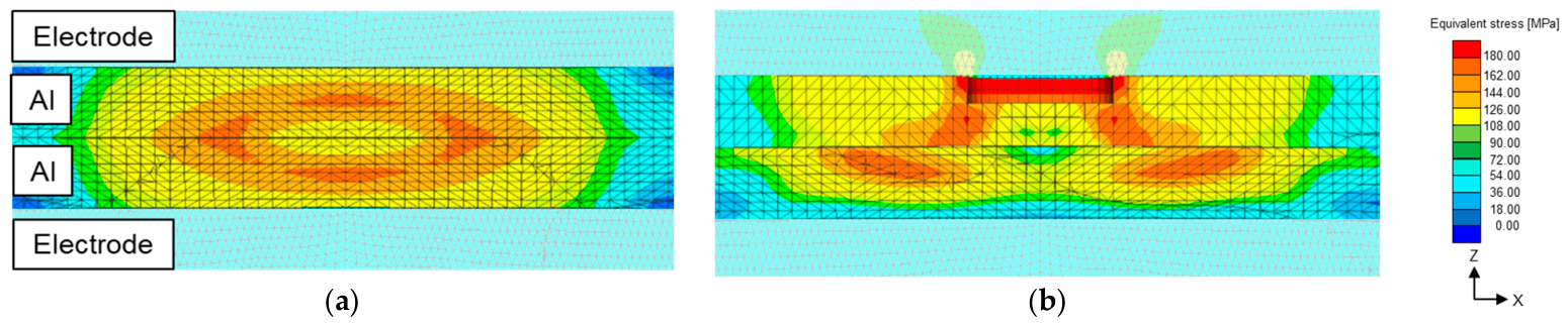
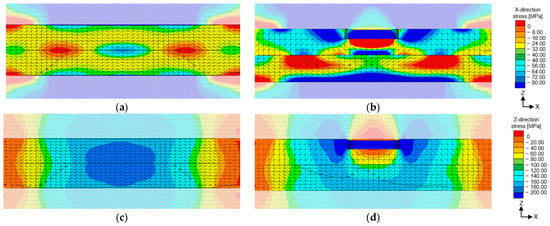
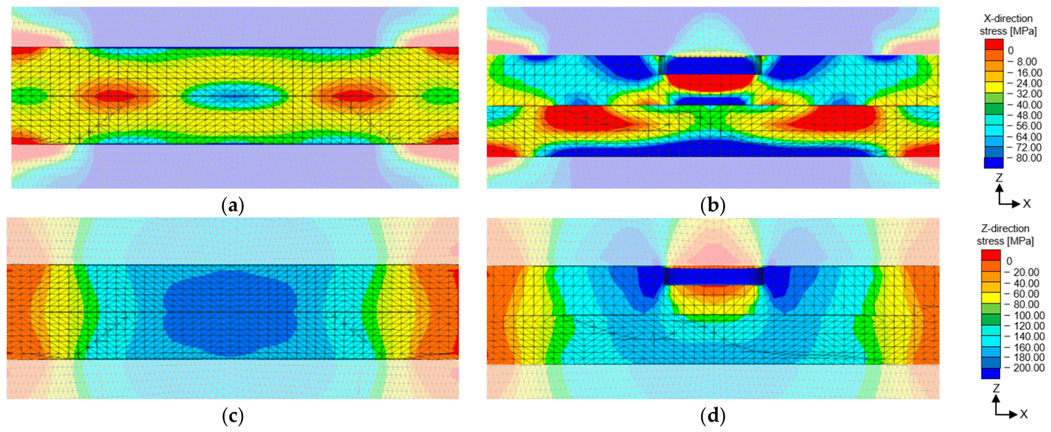
Figure 11 shows the results of the equivalent stress distribution analysis. As shown in Figure 11a, no localized stress concentration was observed, particularly at the sheet–electrode interface under the condition without a hole. In contrast, as shown in Figure 11b, under the hole condition, localized stress concentration was observed at the hole edge at both the sheet–electrode and sheet–sheet interfaces. Next, the analytical results for stress distribution in the X and Z directions are presented. As shown in Figure 12a,b, no localized stress concentration was observed in the X direction under either condition. On the other hand, as shown in Figure 12c,d, localized stress concentration in the Z direction was observed only under the hole condition. Specifically, under the no-hole condition, no localized stress concentration was observed, whereas under the hole condition, clear stress concentration occurred at the hole edge at both the sheet–electrode and sheet–sheet interfaces. These results indicate that the introduction of a hole enables control of the stress concentration location, particularly in the Z direction. Under the no-hole condition, the current path is not controlled at either the sheet–electrode or sheet–sheet interface, resulting in fluctuations in the heat generation location and consequent nugget shape variability. In contrast, under the hole condition, the current path is concentrated at the hole edge at both interfaces, reducing fluctuations in the heat generation location for each weld and thereby suppressing nugget shape variability. These results suggest that stress concentration at the hole edge promotes localized oxide film breakdown, guiding the current path and improving the consistency of nugget formation [10,11].
Figure 11.
Equivalent stress distribution obtained by numerical simulation: (a) equivalent stress distribution under the condition without hole shape; (b) equivalent stress distribution under the condition with hole shape.
Figure 12.
Results of numerical simulation for stress distribution in the X-, and Z-directions: (a) stress distribution in the X-direction under the condition without hole shape; (b) stress distribution in the X-direction under the condition with hole shape; (c) stress distribution in the Z-direction under the condition without hole shape; (d) stress distribution in the Z-direction under the condition with hole shape.
3.3. Results of Consecutive Spot Welding Tests and Nugget Diameter Measurements
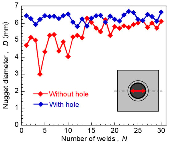
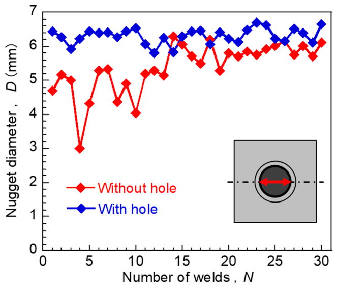
Because the presence of a hole was expected to suppress nugget shape variability and thereby improve continuous weldability, nugget morphology at the faying interface was observed under both conditions. Figure 13 shows the nugget morphologies observed at the interface under the no-hole condition. As shown in Figure 13a–f, the nugget shape varied depending on the number of welds. In contrast, Figure 14 shows the nugget morphologies observed at the interface under the hole condition. As shown in Figure 14a–f, variation in nugget morphology was suppressed under the hole condition regardless of the number of welds. These results suggest that the introduction of a hole reduces nugget shape variability, which in turn contributes to suppression of nugget diameter variation. Nugget diameter was then measured quantitatively. As shown in Figure 15, under the no-hole condition, nugget diameter exhibited large variations depending on the number of welds. In contrast, under the hole condition, nugget diameter variation was clearly suppressed.
Figure 13.
Results of consecutive spot welding under the condition without hole shape: (a) results of the fifth joining process (N5); (b) results of the tenth joining process (N10); (c) results of the fifteenth joining process (N15); (d) results of the twentieth joining process (N20); (e) results of the twenty-fifth joining process (N25); (f) results of the thirtieth joining process (N30).
Figure 14.
Results of consecutive spot welding under the condition with hole shape: (a) results of the fifth joining process (N5); (b) results of the tenth joining process (N10); (c) results of the fifteenth joining process (N15); (d) results of the twentieth joining process (N20); (e) results of the twenty-fifth joining process (N25); (f) results of the thirtieth joining process (N30).
Figure 15.
Measurement results of nugget diameter in consecutive spot welding under the condition without hole shape and the condition with hole shape.
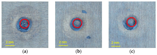
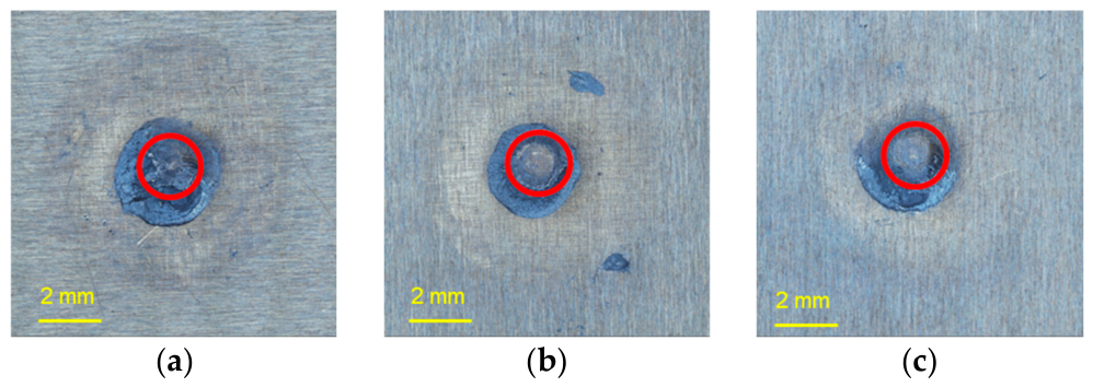
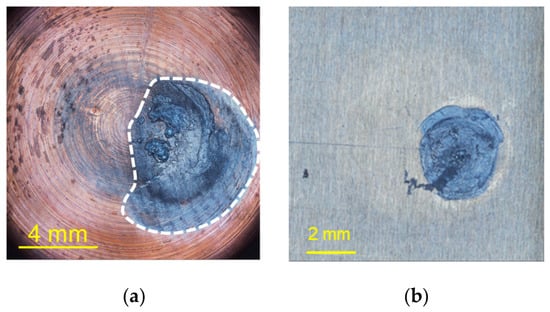
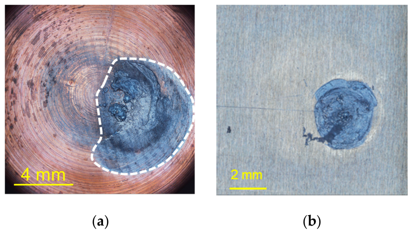
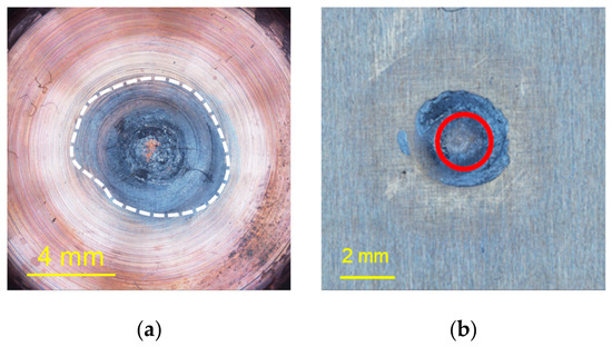
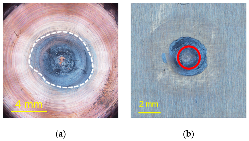
Regarding the factor behind the fluctuation in nugget diameter under the no-hole condition, observation of the electrode surface revealed that aluminum deposition had formed on the lower right area, as shown in Figure 16a. Consequently, as shown in Figure 16b, the initial nugget formation was observed to be offset toward the location of aluminum deposition. These results suggest that the current path was altered by the presence of electrode deposits. In contrast, under the hole condition, the aluminum deposition was formed at the center of the electrode, as shown in Figure 17a. Correspondingly, as shown in Figure 17b, the initial nugget formation was also centered without any deviation. Based on these surface observations, these results suggest that the current path was consistently controlled near the center under the hole condition. This stabilization of the current path likely suppressed the fluctuation in nugget diameter during continuous spot welding.
Figure 16.
Results of surface condition of electrode and observation results of the nugget at the interface at a current passage time of 5 ms under the condition without hole shape: (a) results of surface observation of the electrode after 30 welds; (b) results of the formation of the weld nugget during the first 5 ms of current flow in the electrode after 30 welds.
Figure 17.
Results of surface condition of electrode and observation results of the nugget at the interface at a current passage time of 5 ms under the condition with hole shape: (a) results of surface observation of the electrode after 30 welds; (b) results of the formation of the weld nugget during the first 5 ms of current flow in the electrode after 30 welds.
4. Conclusions
This study investigated the effect of introducing a hole on the sheet surface on nugget shape variability in resistance spot welding of aluminum alloys. The results demonstrated that the introduction of a hole significantly reduces variation in nugget diameter by stabilizing nugget formation.
Observations of the joint interface revealed that nugget shape variability was suppressed under the hole condition. In addition, early-stage observations indicated that variation in the heat generation location was reduced when a hole was introduced. Stress analysis further showed that stress concentration occurs at the hole edge, which promotes localized oxide film breakdown at this location. This localized breakdown contributes to the stabilization of the current path.
Furthermore, consecutive spot welding tests confirmed that variation in nugget diameter was also reduced under the hole condition. These results indicate that controlling stress concentration at the hole edge effectively stabilizes the heat generation location and current path, thereby suppressing nugget shape variability in resistance spot welding of aluminum alloys.
Author Contributions
Conceptualization, Y.M. and M.I.; methodology, Y.M. and M.I.; validation, Y.M., A.I. and M.I.; investigation, Y.M., A.I. and M.I.; data curation, Y.M. and A.I.; writing-original draft preparation, Y.M.; writing-review and editing, Y.M.; supervision, M.I.; project administration, M.I.; funding acquisition, M.I. All authors have read and agreed to the published version of the manuscript.
Funding
This research received no external funding.
Institutional Review Board Statement
Not applicable.
Informed Consent Statement
Not applicable.
Data Availability Statement
No new data were created or analyzed in this study. Data sharing is not applicable to this article.
Conflicts of Interest
The authors declare no conflict of interest.
References
- Hyung, C.K.; Timothy, J.W. Life-Cycle Energy and Greenhouse Gas Emission Benefits of Lightweighting in Automobiles: Review and Harmonization. Environ. Sci. Technol. 2013, 47, 6089–6097. [Google Scholar] [CrossRef] [Scilit]
- Zhong, L.; Guo, Y.; Ji, S.; Han, L. Research on the Improvement of Weldability in Resistance Spot Welding of 6-Series Aluminum Alloys. Int. J. Mech. Eng. Appl. 2023, 11, 113–124. [Google Scholar] [CrossRef] [Scilit]
- Bamberg, P.; Seewald, R.; Schiebahn, A.; Reisgen, U.; Precoma, N.; Epperlein, M. Improvement of the resistance spot welding of Al-Mg-Si alloys by using cladding technology: An optical and mechanical characterization study. J. Adv. Join. Process. 2022, 5, 100090. [Google Scholar] [CrossRef] [Scilit]
- Hisanori, D.; Kinya, A.; Masakuni, E. Friction stir welding of aluminum alloy and application to structure. J. Jpn. Inst. Light Met. 2000, 4, 166–172. [Google Scholar] [CrossRef]
- Fukuda, T. Joining Technology with Lightweight Material Aluminum Alloy. J. Jpn. Weld. Soc. 2015, 84, 519–527. [Google Scholar] [CrossRef] [Scilit]
- Marcell, G.; Ádám, D.; Miklós, T.; Imre, T.; Yangchun, D.; Kailun, Z. Improving the properties of AA7075 resistance spot-welded joints by chemical oxide removal and post weld heat treating. Weld. World 2020, 64, 2119–2128. [Google Scholar] [CrossRef] [Scilit]
- Kondo, M.; Nagata, H.; Nishimura, A.; Kokawa, H. Joining Degradation Mechanism of Electrode Tip during Resistance Spot Welding of Aluminum Alloy Sheets. J. Jpn. Weld. Soc. 2010, 28, 177–186. [Google Scholar] [CrossRef] [Scilit][Green Version]
- Bo, W.S.; Hwi, J.S.; Sung, B.H.; In, S.J.; Chang, J.K.; Young, T.C. Prediction of tensile strength in aluminum spot welding using machine learning. Sci. Rep. 2025, 15, 42735. [Google Scholar] [CrossRef] [Scilit]
- Rashid, M.; Medley, J.B.; Zhou, Y. Nugget formation and growth during resistance spot welding of aluminium alloy 5182. Can. Metall. Q. 2011, 50, 61–71. [Google Scholar] [CrossRef] [Scilit]
- Kimura, K.; Ohsumi, M. A Study on the Influence of the Surface Condition on the Quality of Spot Welding. J. Jpn. Weld. Soc. 1968, 37, 230–237. [Google Scholar] [CrossRef] [Scilit]
- Brechelt, S.; Wiche, H.; Junge, J.; Gustus, R.; Schmidt, H.; Wesling, V. Increase of electrode life in resistance spot welding of aluminum alloys by the combination of surface patterning and thin-film diffusion barriers. Weld. World 2023, 67, 2703–2714. [Google Scholar] [CrossRef] [Scilit]





Disclaimer/Publisher’s Note: The statements, opinions and data contained in all publications are solely those of the individual author(s) and contributor(s) and not of MDPI and/or the editor(s). MDPI and/or the editor(s) disclaim responsibility for any injury to people or property resulting from any ideas, methods, instructions or products referred to in the content. |
© 2026 by the authors. Licensee MDPI, Basel, Switzerland. This article is an open access article distributed under the terms and conditions of the Creative Commons Attribution (CC BY) license.