


Abstract
Aluminium remains relatively uncommon in civil structures; however, its durability and light-weight nature make it an attractive alternative for vehicular bridges. Recent applications use aluminium bridge decks supported by steel girders. However, galvanic corrosion and thermal incompatibility limit full and optimised behaviour. This research explores the use of Bobbin Tool Friction Stir Welding (BTFSW), which improves the welded aluminium behaviour while significantly improving fatigue detail classification, as it is critical for bridges. This configuration optimises material use, reduces structural weight, and supports Accelerated Bridge Construction (ABC) practices by enabling modular prefabrication and rapid installation. The findings highlight aluminium’s potential as a primary bridge material.
1. Introduction
Bridges are typically designed for a service life exceeding 75 years. To achieve this target, however, traditional materials such as steel and concrete require frequent maintenance, especially in harsh climates like Quebec’s. The extensive use of de-icing salts creates corrosive conditions that degrade steel bridges and reinforcement, resulting in approximately 30% of the 7000 bridges managed by the Ministry of Transportation of Quebec requiring repair or replacement [1]. Consequently, there is a critical need for more durable structural alternatives.
Aluminium is a compelling option. Beyond its high strength-to-weight ratio, which simplifies accelerated construction and the reuse of existing foundations, it forms a stable surface oxide layer that provides inherent corrosion protection without supplementary coatings [2]. Furthermore, aluminium alloys maintain high toughness and ductility at low temperatures, making them ideal for cold climates [3,4]. The Arvida Bridge in the province of Quebec, an 88.4 m span arch erected in 1950, exemplifies this durability; it has surpassed 75 years of service without significant structural maintenance.
Despite these advantages, challenges such as a lower modulus of elasticity compared to steel can lead to increased deflections and dynamic sensitivity [5]. Welding also reduces local strength by up to 50% [6], and fatigue remains a critical issue due to higher crack growth rates than steel [7]. Additionally, aluminium’s high coefficient of thermal expansion complicates composite action with other materials [8].
This paper proposes a structural concept for an all-aluminium bridge optimised for material efficiency and fatigue performance. The design leverages the geometric versatility of extrusions and utilises Bobbin Tool Friction Stir Welding (BTFSW) to enhance welded joint resistance. By using aluminium exclusively, the deck contributes to the longitudinal load-carrying mechanism, improving global efficiency. This concept aligns with prefabrication and is highly compatible with Accelerated Bridge Construction (ABC) strategies.
2. Aluminium in Vehicular Bridges
The use of aluminium in vehicular bridges has primarily been seen in bridge decks. In the event of replacing an old deck, aluminium is highly advantageous, as an aluminium deck can weigh as little as 20% of a comparable concrete deck [5]. These decks are fabricated by joining and welding individual extrusions together. The main constraint in designing aluminium decks is the maximum size of the extrusion, which is limited by the capacity of extrusion presses. This capacity is directly related to the maximum circumscribing circle diameter and the weight per unit length of the profile.
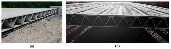
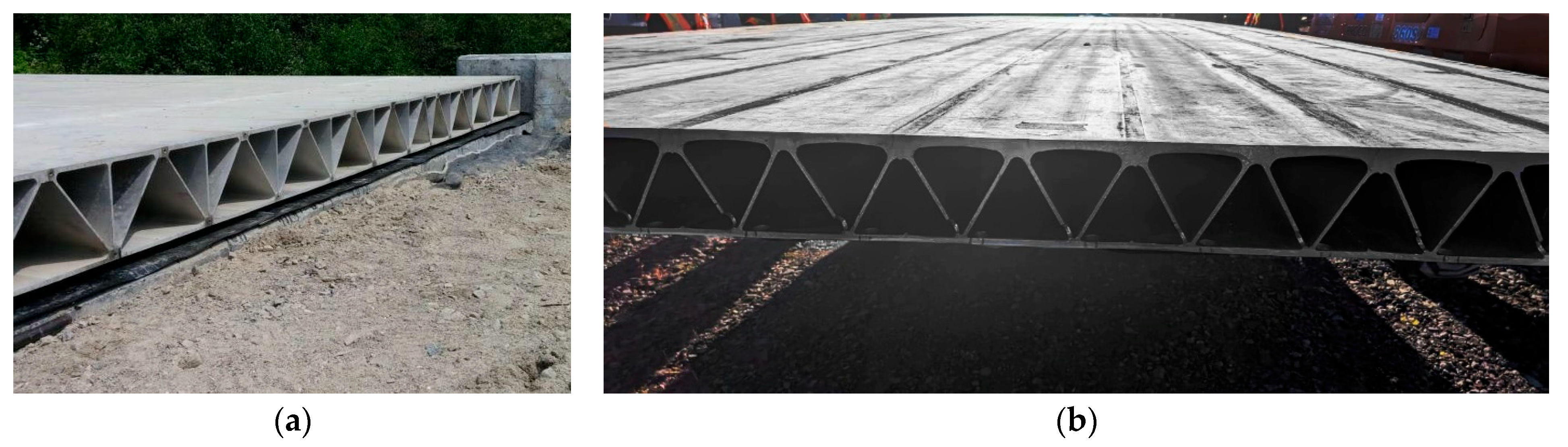
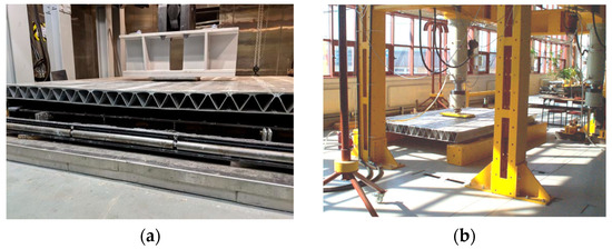
Various deck systems have been developed and tested using different joining methods, ranging from traditional Gas Metal Arc Welding (GMAW) to Friction Stir Welding (FSW), as shown in Figure 1. These decks have undergone rigorous laboratory testing and have been implemented in real-world projects [8,9,10,11,12,13]. In general, studies concluded that aluminium decks are highly capable of resisting traffic loads, satisfying both ultimate resistance and fatigue requirements. Observed failure modes typically involved the fracture of welds or the local buckling of stiffeners combined with yielding at the load patch.
Figure 1.
Aluminium bridge decks: (a) Friction Stir Welding (FSW) [8]; (b) Gas Metal Arc Welding (GMAW).
Aside from decks, aluminium has also been used as the primary structural material in a limited number of vehicular bridges. As previously mentioned, the Arvida Bridge in Quebec stands as a landmark structure built in 1950. The Forsmo Bridge in Norway is another notable example [4], where a steel–concrete structure was replaced by a 39 m span aluminium bridge within a total closure period of only five days. Furthermore, in Russia, a new four-span, 72 m bridge was constructed using aluminium for both the deck and the girders [14].
3. Development of a BTFSW Aluminium Deck
Decks must be designed to satisfy serviceability (SLS), ultimate (ULS), and fatigue (FLS) limit states. ULS ensures the overall resistance and stability of the deck. While the design process using code provisions, such as the Canadian Highway Bridge Design Code (CSA S6-25) [15], is generally straightforward, there is a lack of guidance regarding simplified models for structural analysis, such as the equivalent strip method used for concrete decks.
For SLS, which governs the limitation of excessive deflections and user discomfort, the standard guidelines used for orthotropic steel decks in AASHTO [16] are adopted in codes like CSA S6-25. A deflection limit of L/1000 between the supports of the aluminium deck reflects the original provisions for the deflections of orthotropic steel deck ribs between crossbeams. Additionally, a limit of 2.54 mm for relative deflection between adjacent ribs and a maximum deflection of L/300 for the deck plate are recommended.
For FLS, the design is particularly critical. Studies report that FSW joints perform better than GMAW joints in bridge decks [13]. However, FSW details tend to fall into a lower fatigue detail category; the requirement for backing bars to support vertical loads creates stress concentrations and potential crack initiation points (classified as Detail Category D in CSA S6-25). Furthermore, from a design perspective, simplified nominal stress approaches may not adequately capture local stress distributions; therefore, methods such as the effective notch stress approach may be required [17].
Another critical consideration is that decks are subjected to biaxial stresses. Although the primary load-carrying mechanism distributes the load to adjacent girders (inducing stresses transverse to traffic), the wheel load patch also generates stresses parallel to traffic, resulting in tensile stresses at the bottom of the deck. Finite element analyses have shown that the rotation of the principal stress plane during the passage of a wheel load is less than 20°; therefore, in accordance with the International Institute of Welding (IIW) guidelines [18], the assumption of proportional loading is permitted. Consequently, fatigue must be evaluated for this multiaxial stress state. The IIW provides guidance on how to address this condition, as shown in Equation (1). and are the applied normal and shear stress ranges ( stands for perpendicular to the weld and for parallel to the weld), while and stand for the normal and shear fatigue resistance given by S-N curves.
To apply this equation, an adjustment is required because the standard development of the fatigue curve assumes a cumulative damage factor D = 1, based on Miner’s sum [19]. According to the IIW, a factor D = 0.5 must be used instead. Consequently, it can be demonstrated that the allowable stress ranges specified in design codes, which are calculated based on D = 1.0, must be transformed into Equation (2). For a fatigue curve with inverse slope m = 7.0, the stress range corresponding to D = 0.5 equates to 90% of the admissible stress provided by the code.
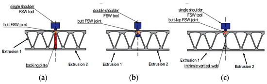
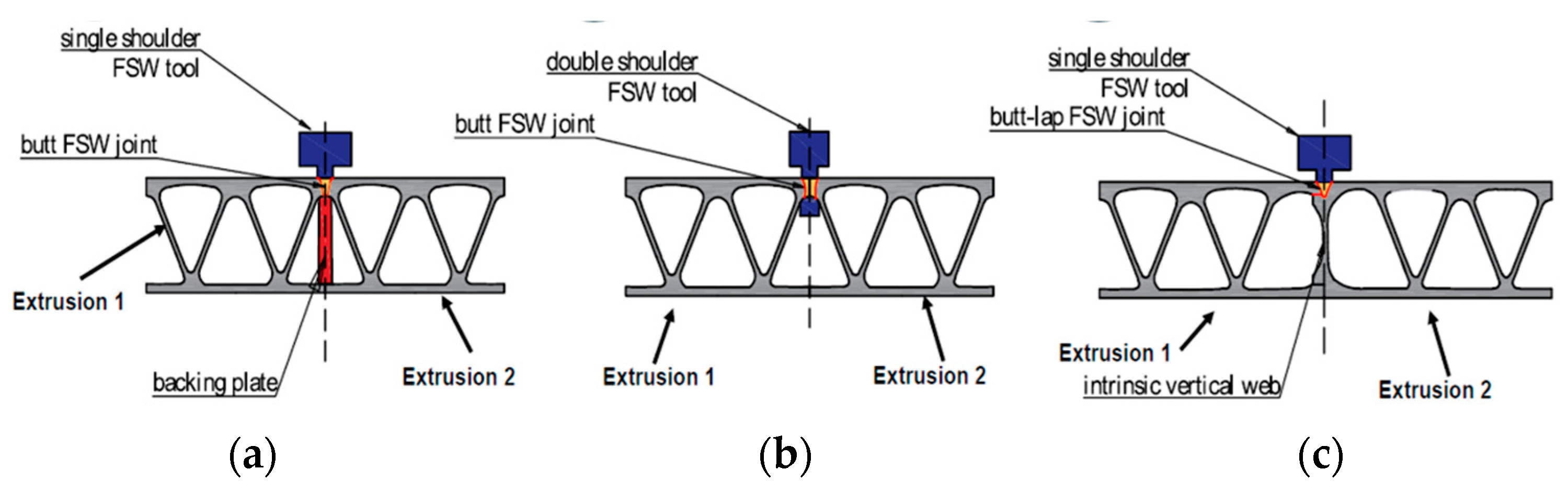
To date, aluminium decks have primarily been fabricated using either GMAW or conventional FSW; however, an alternative joining process offers distinct advantages. BTFSW, a variant of the FSW process, utilises a double-sided shoulder tool that contains the transmitted vertical forces, thereby eliminating the need for a backing bar. As a result, the fatigue detail classification improves to a higher category (Detail Category B in CSA S6-25), achieving a significantly higher fatigue resistance. Figure 2 illustrates the difference between the conventional FSW process (which requires external or intrinsic backing) and BTFSW.
Figure 2.
Friction Stir Welding (FSW) of aluminium decks [17]: (a) FSW with external backing plate; (b) Bobbin Tool Friction Stir Welding (BTFSW); (c) FSW with intrinsic backing plate.
However, BTFSW imposes certain limitations on the weld configuration. The joint must be a flat butt weld with a minimum flat clearance of at least 26 mm to accommodate the welding tool [20]. Additionally, there are restrictions on the maximum thickness of the welded plates. Currently in Quebec, BTFSW has been proved effective for a maximum plate thickness of 8 mm [21], and an increase to a 9.5 mm capacity is under development. Therefore, it is of significant interest to develop an optimised deck shape suitable for BTFSW that successfully accommodates both the spatial clearance requirements of the tool and a maximum anticipated plate thickness of 9.5 mm.
3.1. Finite Element Model
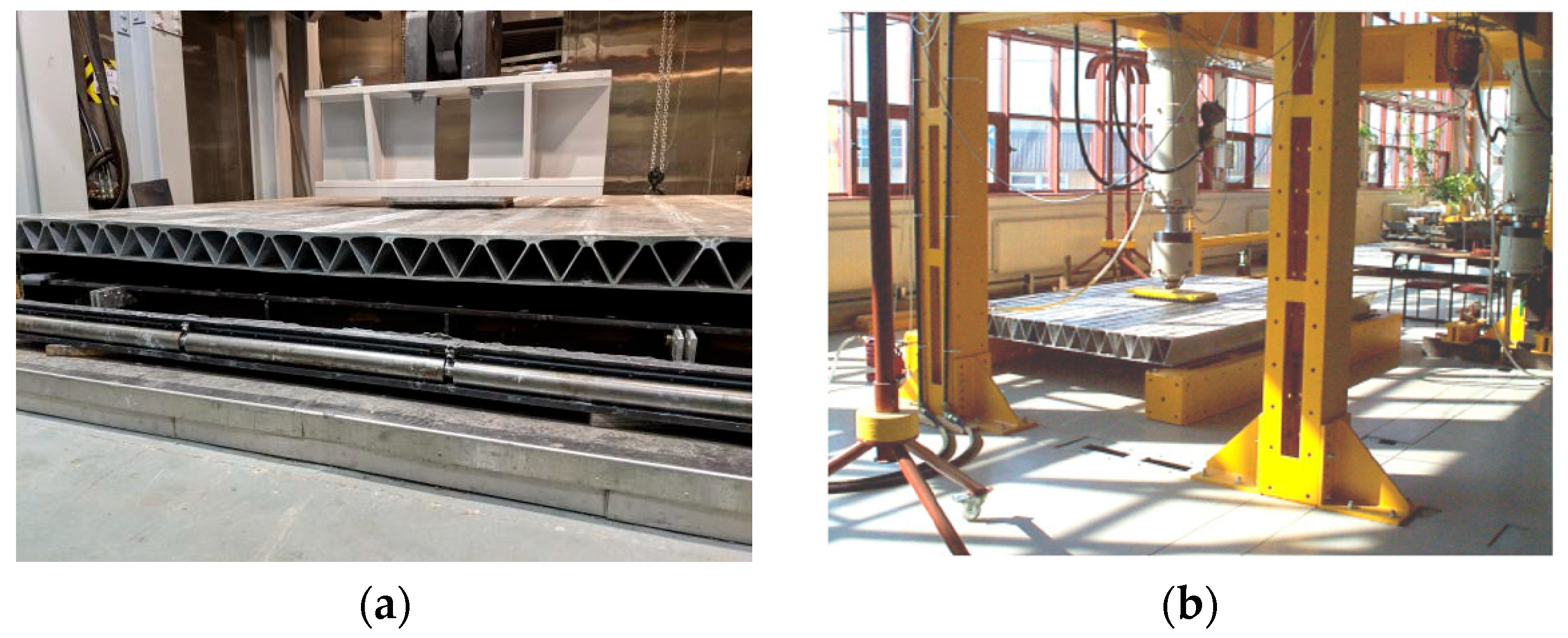
A Finite Element (FE) model was developed in Abaqus to study various geometries for aluminium decks. First, the modelling approach was validated through comparison with previous experimental tests, as shown in Figure 3 [9,10]. The models were discretised using either shell S4R elements or solid C3D8I elements; the latter were specifically selected to adequately capture local bending mechanics. Mesh sizes were determined following a convergence study, resulting in a maximum element size of 15 mm for the solid models and 12 mm for the shell models. A non-linear material constitutive law following the Ramberg-Osgood relation was implemented, as recommended in Annex E of Eurocode 9 [22], utilising reported material parameters for both the base metal and the reduced-strength Heat Affected Zone (HAZ). The extent of the HAZ was defined in accordance with the CSA S6-25 code, with a width ranging between 20 mm and 30 mm. To accurately replicate the experimental conditions, the load was applied through a low-stiffness rubber pad matching the exact dimensions of the physical load patch. The non-linear Riks method, incorporating geometric non-linearities, was utilised to solve the model and accurately capture the structural response. Finally, boundary conditions were configured to match the physical tests by imposing simply supported constraints along the extreme edges parallel to the extrusion direction.
Figure 3.
Tested aluminium decks: (a) P1 test, GMAW deck tested in [9]; (b) LC1 test, GMAW deck tested in [10].
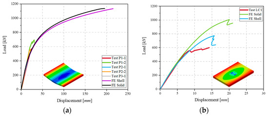
The load–displacement curves comparing the experimental tests against the FE simulations are presented in Figure 4. For both tests, the initial elastic response is captured accurately, with a maximum stiffness deviation of 4% for test P1 and 3% for test LC1. Both shell and solid element models prove adequate, as the stiffness variation in the linear elastic range is less than 5%. In the non-linear range, the shell models exhibit behaviour similar to the solid models; however, the inclusion of fillets in the solid model increases both the overall stiffness and the peak load because the local buckling of the stiffeners occurs over a reduced effective length.
Figure 4.
Comparison between Finite Element (FE) simulation and test load–displacement curves: (a) P1 test [9]; (b) LC1 test [10].
However, the ultimate peak load is not fully captured in the simulations because both experimental decks experienced weld fracture after exceeding their plastic limit. The FE model was not designed to simulate fracture mechanics, which accounts for this discrepancy. Regardless, the design wheel load specified in the CSA S6-25 code is 62.5 kN, and the experimental fracture occurred well above this limit, at approximately 600 kN for both decks. Therefore, within the range of expected service loads, the FE model is considered highly satisfactory and is validated for use in subsequent studies.
3.2. Deck Shape Selection
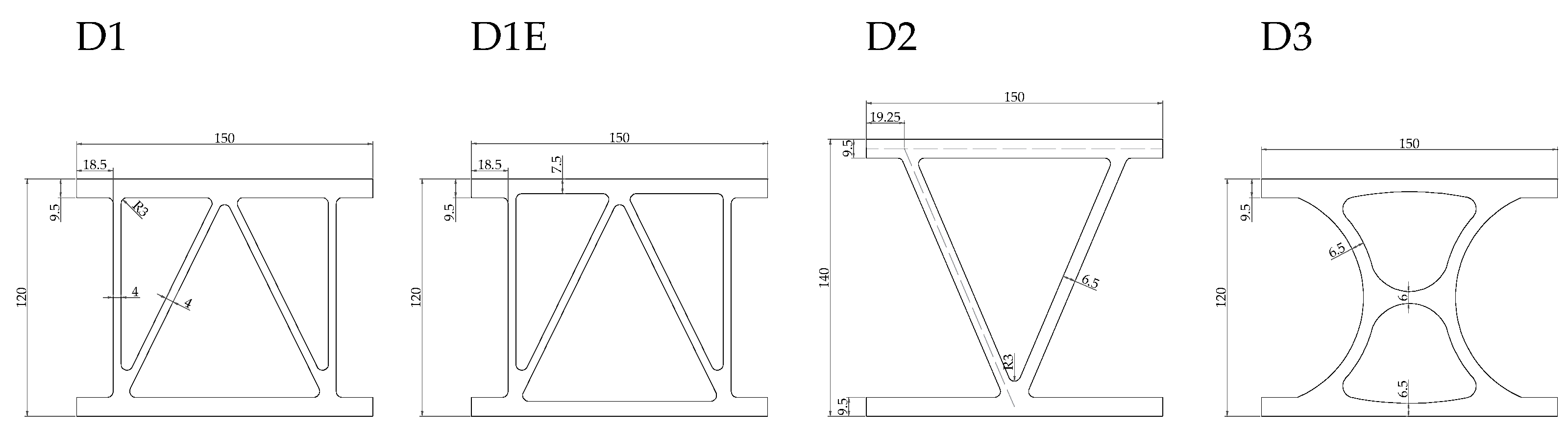
To select an appropriate shape for a BTFSW aluminium deck, five geometries were chosen to study and compare their structural behaviour. All geometries were designed to be extruded with a 9-inch (228.6 mm) maximum circumscribing circle diameter and a linear mass of 12 kg/m, which corresponds to the capacity limits of the largest extrusion press available in Quebec. The thickness of the welded area was set to 9.5 mm, with a minimum overall flat width of 26 mm to accommodate the welding tool. Figure 5 shows the five selected cross-sections of the base extrusions for the decks:
Figure 5.
Base extrusion cross section geometries of the studied decks.
- D1: This geometry incorporates both vertical and diagonal stiffeners, maintaining a uniform thickness for both the welded area and the flanges.
- D1E: This geometry features a welded area that is thicker than the flange elements to compensate for the reduced material properties in the Heat Affected Zone (HAZ). For this geometry, two shell models were created: D1E-exc, which explicitly considers the geometric eccentricity, and D1E-no exc, which disregards it.
- D2: This geometry prioritises overall deck depth over the inclusion of vertical stiffeners, which are eliminated in this design.
- D3: This geometry replicates the optimised profile developed by Djedid [20] in a similar prior study.
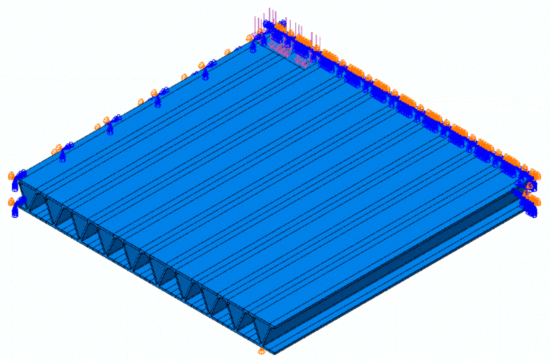
FE models of 3 m × 3 m panels with simply supported boundary conditions along the edges parallel to the extrusions were created, as shown in Figure 6. Only linear elastic material properties were considered, as the anticipated service loads fall within this range. A design load of 62.5 kN was applied over a load patch of 600 mm × 250 mm. Double symmetry boundary conditions were utilised, thereby reducing the computational domain to one quarter of the deck. Local mesh refinement was applied near the point of maximum stress within the weld.
Figure 6.
Finite Element (FE) model in Abaqus of the BTFSW aluminium deck.
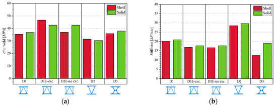
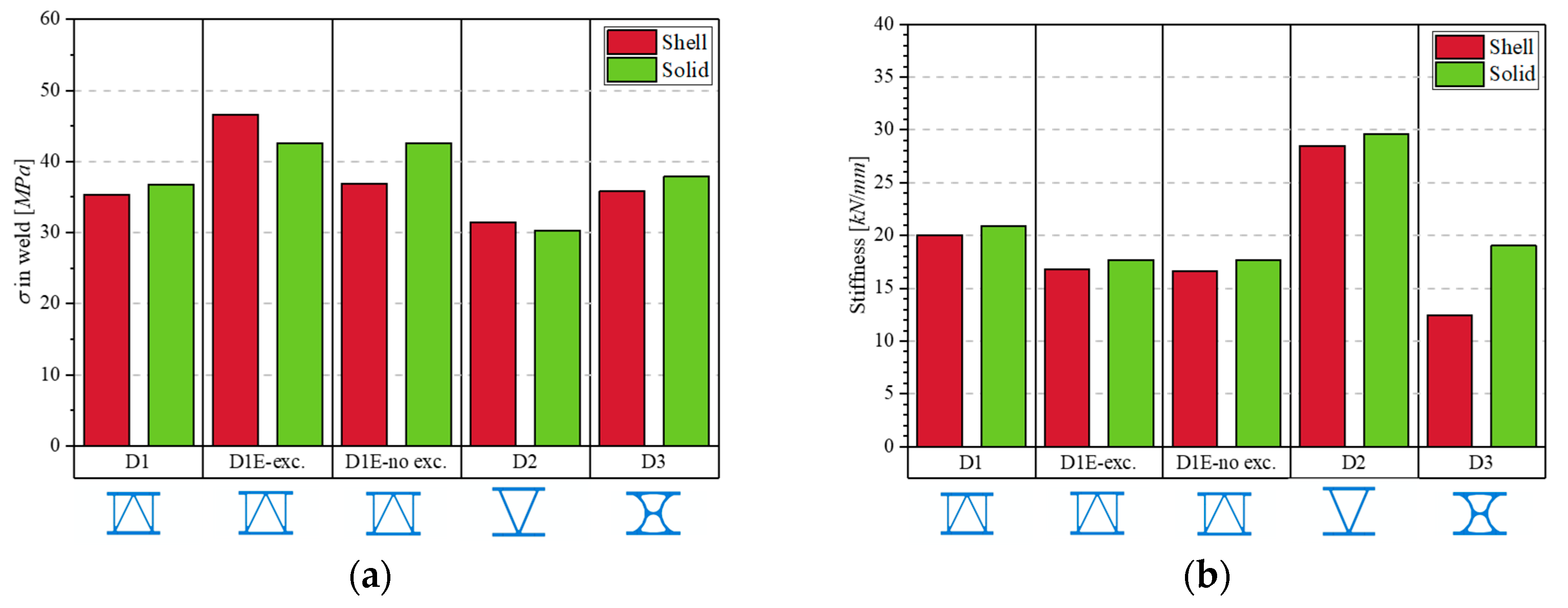
The performance comparison was based on optimisation for SLS (evaluated by panel stiffness) and FLS (evaluated by the maximum transverse tensile stress in the weld). The results are presented in Figure 7. The D2 geometry experienced lower stresses in the weld (30 MPa vs. 35 MPa for D1) and demonstrated greater stiffness (29 kN/mm vs. 20 kN/mm for D1). This improvement is attributed to the increased height of the D2 geometry (140 mm compared to 120 mm for D1), demonstrating that prioritising deck depth over vertical stiffeners yields more favourable results for these limit states.
Figure 7.
Results of the studied geometries: (a) Maximum transverse tensile stress in the weld [MPa]; (b) Stiffness of the deck [kN/mm].
The results indicate that the shell models adequately captured both the stresses and the stiffness of all deck geometries, with the exception of D3, where the stiffness predicted by the shell model was only 66% of that predicted by the solid model.
Finally, the effect of modelling eccentricity in the shell elements was notable, as it increased the predicted stress in the weld by 26%. However, the stress value obtained from the solid model, which inherently accounts for both the eccentricity and the geometric stiffening effect of the fillets, fell between the values predicted by the two shell model variations.
Therefore, geometry D2 is selected for further analyses using shell elements, as it offers the best structural performance while remaining reliably represented by the modelling approach.
4. Bridge Concept
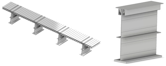
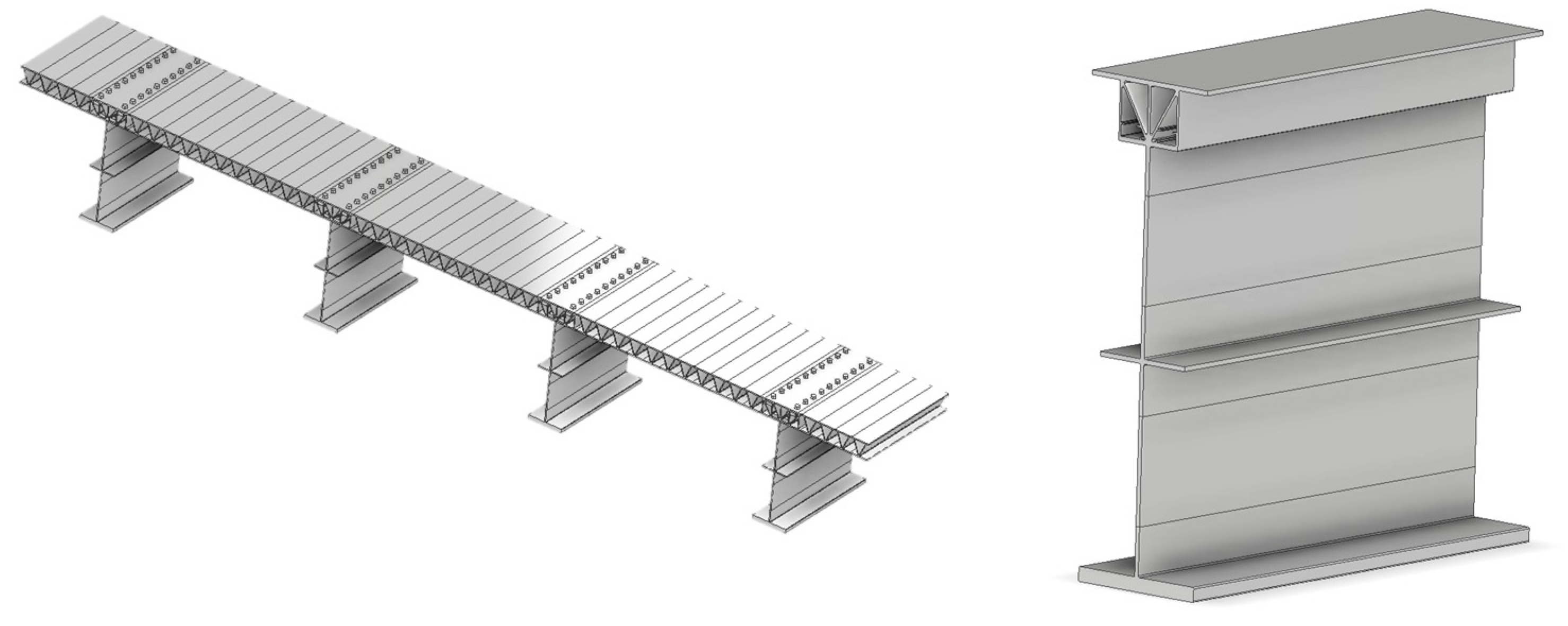
Following the selection of the optimised bridge deck geometry D2, the full-bridge concept is illustrated in Figure 8. The deck is designed to be connected to the girders using the bolted plate technique [23,24]. The girders are similarly fabricated by joining multiple extrusions using BTFSW. This approach allows for a customised selection of each extrusion, providing the flexibility to include specific geometric details, such as longitudinal stiffeners, to enhance shear resistance. Furthermore, this concept aligns perfectly with Accelerated Bridge Construction (ABC) methodologies, as it is fully prefabricable.
Figure 8.
BTFSW all-aluminium bridge concept.
5. Ongoing Research
A preliminary analysis of this all-aluminium concept is detailed in reference [25]. Initial findings demonstrate that the deck and global superstructure provide adequate capacity for both ULS and FLS. However, satisfying SLS requires a more rigorous investigation, such as an in-depth dynamic study or the implementation of dampers to mitigate vibrations. The analysis also highlighted that structural detailing heavily governs the global design; specifically, utilising welded attachments for cross-brace connections reduces fatigue and bending resistance by approximately 50%. Consequently, the design strategy must prioritise bolted connections over welding at these critical junctions.
Finally, applying this concept to a case-study bridge demonstrated significant weight savings: the structural mass was reduced by 78% compared to a traditional steel-concrete alternative, yielding a total bridge mass that is only 47% of the original design. Based on these initial findings, an all-aluminium bridge presents a highly promising structural solution, suitable for both the replacement of deteriorating infrastructure and the construction of new bridges.
To validate the preliminary findings of this study and further refine the structural concept, several research initiatives are currently underway. First, a comprehensive investigation into bridge vibrations is being conducted to accurately characterise the dynamic behaviour of the light-weight superstructure. Concurrently, an experimental laboratory testing programme is planned to physically evaluate the static and fatigue performance of the developed BTFSW aluminium deck. A primary objective of this testing is to establish the validity of fatigue resistance (S–N) curves for this deck system and to experimentally verify the biaxial fatigue interaction equations. Furthermore, simplified design guidelines are being formulated to streamline structural analysis for practical bridge engineering. Finally, a Life Cycle Cost Analysis (LCCA) will be executed to quantify the long-term economic and environmental feasibility of this all-aluminium solution compared to traditional steel and concrete alternatives.
6. Conclusions
This paper presented the development and preliminary analysis of an all-aluminium vehicular bridge concept utilising Bobbin Tool Friction Stir Welding (BTFSW). Based on the numerical investigations and geometric optimisation, the following main conclusions are drawn:
- An optimised BTFSW deck shape prioritising overall deck depth over internal vertical stiffeners yields the most favourable structural behaviour. This configuration leverages the advantages of aluminium welded by FSW while enhancing fatigue resistance through an improved fatigue detail classification.
- Simplified shell element models are generally adequate for predicting the linear elastic stiffness and stress distributions of the extruded deck profiles. However, capturing the true geometric eccentricity in these shell models is critical; explicitly modelling this eccentricity was shown to increase the predicted transverse weld stresses by up to 26%, more accurately reflecting the physical structural response.
- Overall, the integration of customised aluminium extrusions, high-resistance BTFSW joints, and modular bolted connections presents a highly promising structural solution, with further research underway to confirm these initial findings. This light-weight, prefabricable system is exceptionally well suited for Accelerated Bridge Construction (ABC) and the sustainable replacement of deteriorating infrastructure.
Author Contributions
Conceptualization, P.R., M.A. and N.B.; methodology, P.R., M.A. and N.B.; software, P.R.; validation, P.R. and N.B.; formal analysis, P.R.; investigation, P.R.; resources, P.R. and N.B.; data curation, P.R.; writing—original draft preparation, P.R.; writing—review and editing, P.R., M.A. and N.B.; visualization, P.R., M.A. and N.B.; supervision, N.B.; project administration, N.B.; funding acquisition, N.B. All authors have read and agreed to the published version of the manuscript.
Funding
We acknowledge the support of the Natural Sciences and Engineering Research Council of Canada (NSERC) [Alliance 466486288], the Centre Québécois de Recherche et de Développement de l’Aluminium (CQRDA), Rio Tinto, WSP, Metra, Proco and AluQuébec.
Institutional Review Board Statement
Not applicable.
Informed Consent Statement
Not applicable.
Data Availability Statement
The data presented in this study is available on request from the corresponding author.
Acknowledgments
The authors would like to thank NSERC, CQRDA, Rio Tinto, WSP, Metra, Proco and AluQuébec for their financial and technical support. During the preparation of this manuscript, the authors used Gemini 3 for the purposes of polishing the English language. The authors have reviewed and edited the output and take full responsibility for the content of this publication.
Conflicts of Interest
The authors declare no conflicts of interest.
References
- Ministère des Transports et de la Mobilité Durable du Québec Inventories and Inspection of Structures. Available online: https://www.transports.gouv.qc.ca/fr/projets-infrastructures/structures/Pages/inventaires-structures.aspx (accessed on 12 January 2026).
- Mazzolani, F.M. Competing Issues for Aluminium Alloys in Structural Engineering. Prog. Struct. Eng. Mater. 2004, 6, 185–196. [Google Scholar] [CrossRef] [Scilit]
- Das, S.K.; Kaufman, J.G. Aluminum Alloys for Bridges and Bridge Decks; The Minerals, Metals & Materials Society: Pittsburgh, PA, USA, 2007. [Google Scholar]
- Tindall, P. Aluminium in Bridges. In ICE Manual of Bridge Engineering, 2nd ed.; Parke, G., Hewson, N., Eds.; ICE Publishing: London, UK, 2008. [Google Scholar]
- Siwowski, T. Aluminium Bridges—Past, Present and Future. Struct. Eng. Int. 2006, 16, 286–293. [Google Scholar] [CrossRef] [Scilit]
- Höglund, T.; Nilsson, L. Aluminium in Bridge Decks and in a New Military Bridge in Sweden. Struct. Eng. Int. 2006, 16, 348–351. [Google Scholar] [CrossRef] [Scilit]
- Georgantzia, E.; Kashani, M.M. On the Use of Aluminium Alloys in Sustainable Design, Construction and Rehabilitation of Bridges. In Proceedings of the Institution of Civil Engineers-Bridge Engineering; Emerald Publishing Limited: Leeds, UK, 2024; pp. 1–13. [Google Scholar] [CrossRef] [Scilit]
- Cusson, B. Designing and Detailing a GMAW Welded Aluminium Deck on Steel Girders for CSA S6: 19 Traffic Loads. In Proceedings of the 11th International Conference on Short and Medium Span Bridges, Toronto, ON, Canada, 19–22 July 2022. [Google Scholar]
- Sanchez, T.; Desjardins, V.; Coderre, T.; Hicham, C.; Picard, D.; Ferland, H.; Djedid, A. Rapport Final Du Projet de Recherche R786. 1—Développement d’une Solution de Platelage En Aluminium Pour Pont Routier à Poutres D’acier; Rapport de Recherche Réalisé Pour Le Compte Du Ministère Des Transports, de La Mobilité Durable et de l’Électrification Des Transports; Ministère des Transports: Québec City, QC, Canada, 2024. [Google Scholar]
- Siwowski, T.W. Structural Behaviour of Aluminium Bridge Deck Panels. Eng. Struct. 2009, 31, 1349–1353. [Google Scholar] [CrossRef] [Scilit]
- Dobmeier, J.M.; Barton, F.W.; Gomez, J.P.; Massarelli, P.J.; McKeel, W.T. Failure Study of an Aluminum Bridge Deck Panel. J. Perform. Constr. Facil. 2001, 15, 68–75. [Google Scholar] [CrossRef] [Scilit]
- Maljaars, J.; Soetens, F.; Van Straalen, I. Fatigue of Aluminium Bridge Decks. Struct. Eng. Int. 2006, 16, 305–311. [Google Scholar] [CrossRef] [Scilit]
- Vigh, L.G.; Okura, I. Fatigue Behaviour of Friction Stir Welded Aluminium Bridge Deck Segment. Mater. Des. 2013, 44, 119–127. [Google Scholar] [CrossRef] [Scilit]
- Korgin, A.V.; Vasiliev, E.V.; Maslov, O.G. The first aluminium alloy road bridge in Russia. Constr. Sci. Educ. 2024, 14, 6–27. [Google Scholar] [CrossRef] [Scilit]
- Canadian Standards Association. Canadian Highway Bridge Design Code CSA S6:25; Canadian Standards Association: Toronto, ON, Canada, 2025. [Google Scholar]
- American Association of State Highway and Transportation Officials (AASHTO). LRFD Bridge Design Specifications; American Association of State Highway and Transportation Officials (AASHTO): Washington, DC, USA, 2024. [Google Scholar]
- Trimech, M.; Annan, C.D.; Walbridge, S.; Maljaars, J. Fatigue Behaviour of Butt-Lap Friction Stir Welded Joints Used with Aluminum Bridge Decks. Structures 2023, 51, 1795–1805. [Google Scholar] [CrossRef] [Scilit]
- Hobbacher, A.F.; Baumgartner, J. Recommendations for Fatigue Design of Welded Joints and Components; IIW Collection; Springer Nature: Cham, Switzerland, 2024. [Google Scholar]
- Coughlin, R.; Walbridge, S. Fatigue Testing and Analysis of Aluminum Welds under In-Service Highway Bridge Loading Conditions. J. Bridge Eng. 2012, 17, 409–419. [Google Scholar] [CrossRef] [Scilit]
- Djedid, A.; Oudjene, M.; Fafard, M. Optimal Extrusion Shape for Fabricating Aluminium Bridge Deck Using Assembly-Based Friction Stir Welding with Bobbin Tool. Eng. Proc. 2023, 43, 36. [Google Scholar] [CrossRef] [Scilit]
- Tinguery, K.M.S.; Rahem, A.; Nadeau, F.; Fafard, M. Friction Stir Welding Parameters Development of AA6061-T6 Extruded Alloy Using a Bobbin Tool. Eng. Proc. 2023, 43, 50. [Google Scholar] [CrossRef] [Scilit]
- EN 1999-1-1:2023; Eurocode 9: Design of Aluminium Structures—Part 1-1: General Structural Rules. European Committee for Standardization: Brussels, Belgium, 2023.
- Buzatu, P.; Cusson, B.; Erian, J.; Fafard, M. Test of Slip-Critical Connection System with Embedded Nuts for Aluminum Bridge Application. Eng. Proc. 2023, 43, 42. [Google Scholar] [CrossRef] [Scilit]
- Cusson, B. Modern Applications and Construction Details for Aluminium Bridges. Eng. Proc. 2023, 43, 13. [Google Scholar] [CrossRef] [Scilit]
- Rico, P.; Amiri, M.; Boissonnade, N. Advancements in Aluminium as a Structural Material for Vehicular Bridges. ce/papers Eurosteel, 2026; Submitted for publication.
Disclaimer/Publisher’s Note: The statements, opinions and data contained in all publications are solely those of the individual author(s) and contributor(s) and not of MDPI and/or the editor(s). MDPI and/or the editor(s) disclaim responsibility for any injury to people or property resulting from any ideas, methods, instructions or products referred to in the content. |
© 2026 by the authors. Licensee MDPI, Basel, Switzerland. This article is an open access article distributed under the terms and conditions of the Creative Commons Attribution (CC BY) license.