


Abstract
This article reports the results of a simulation modelling of a closed-die cold forging process used to manufacture a part made of S235JR. All tools and parts were developed with SolidWorks 2023 CAD software. Two simulation runs, with and without lubricant, were carried out by use of the QForm 11 simulation software. The simulation parameters and results are described in the article. The analysis showed that the simulated process could certainly be used for the manufacturing of quality products with high dimensional precision and improved strength, suitable for use in various industries. It further proved the QForm professional software’s suitability for use in the above industries for precise simulation of various cold and hot working processes.
1. Introduction
Improving the dimensional accuracy and quality of workpieces is among the main objectives of modern-day mechanical engineering. This objective is most fully achieved by using the cold working processes based upon plastic deformation. The most progressive methods based upon cold working by plastic deformation include the mutually complementary processes of sheet metal forming and cold (die) forging [1].
Cold forging contributes to: enhanced deformation strengthening, minimisation of defects, improved dimensional precision (compared to other processes, such as machining, casting, and hot forging), improved utilization of the forged metal, and significantly reduced labour intensity and need for subsequent processing [2,3]. The cold forging processes are distinguished by their high degree of mechanization and automation, which is substantially higher than in the processes of casting and hot forging [4].
Further expansion of the scope of cold forging applications as a replacement for machining, casting, and hot forging can be achieved by improving the process performance characteristics, overcoming the complex shapes constraints, and increasing the overall size of the forged details [3].
The cold forging’s main characteristic is that it is carried out at speeds significantly exceeding those of phase transformations in the workpiece material, which generally cause strength reduction and stress relief [5,6]. As a result, the strength of the deformed material increases considerably. On the one hand, this causes problems in ensuring sufficiently strong tools and introduces limitations to the accuracy class of the processed part, dependent on the ductility properties of its material. On the other hand, in some cases, the process allows for the exclusion of the subsequent hardening heat treatment procedures and the use of cheaper input materials.
The list of materials that are suitable for cold forging is long. Nevertheless, the materials that are commonly processed by using this technology on a large industrial scale are limited to the alloys of aluminum, copper, and nickel, as well as to some low-carbon steel grades. In the industry, cold forging is most frequently used for processing parts of low-carbon and boron steels alloyed with chromium and manganese [7]. The carbon content in those steels, as a rule, does not exceed 0.35%. The increase in the carbon content generally causes an increase in the rate of hardening during the cold plastic deformation [8].
Basic Features of the Manufacturing Process
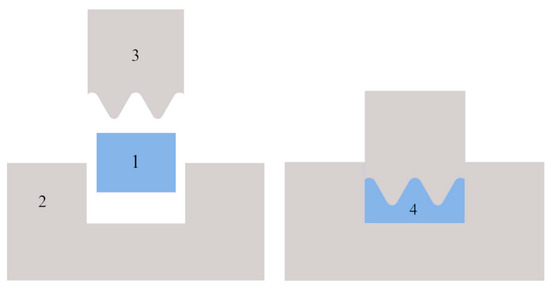
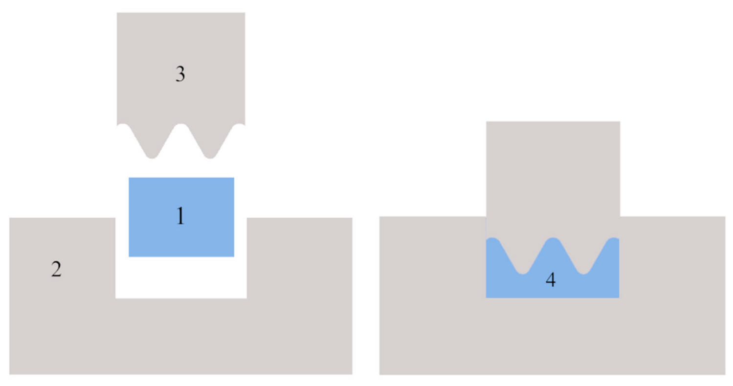
In cold forging, a workpiece with a simple geometry is plastically deformed between two tools (a punch and a die)–Figure 1. As the tools “imprint” the desired shape by applying pressure to the deforming material, the workpiece acquires a more complex geometry. Cold forging usually produces little or no waste and gives the part a final shape in a very short time, usually by applying one or a few blows by the press or hammer [9,10].
Figure 1.
Closed-die cold forging: (1) workpiece, (2) die, (3) punch, (4) product.
2. Methods and Materials
2.1. Material of the Workpiece—Material Specifications
The material used for the workpiece is structural steel grade S235JR. The steel belongs to the low-carbon steels and is specially developed for use in construction, as well as in many other industries. The excellent machinability of S235JR allows the precise manufacturing of parts with complex geometric shapes and small tolerances. Its ability to withstand the working processes without compromising its structural integrity makes it an ideal choice for the manufacture of high-quality products. Steel grade S235JR is characterized by exceptional durability and wear resistance.
The mechanical properties of S235JR make it suitable for various structural applications. Its strength characteristics provide sufficient load-bearing capacity, while its good ductility allows for considerable deformations without structural failures. These properties are essential for structures that are subjected to high dynamic loads. Due to its favourable mechanical properties, S235JR is widely used in construction, automotive, machine building, and shipbuilding industries.
The steel’s strength and durability make it ideal for the manufacturing of parts with increased requirements for their service lives, thus effectively contributing to the final products’ overall longevity. However, its constraints include lower corrosion resistance compared to high-alloy steels, which may require the application of a protective coating to ensure the product’s use in certain aggressive environments [11].
Table 1 lists the alternative designations of the steel, while Table 2 shows the chemical composition of S235JR, as well as the major elements having a significant influence on its properties.
Table 1.
Alternative designations of steels.
Table 2.
Chemical composition.
2.2. Materials for Manufacturing of the Tools
The materials used for the punch and die are X155CrVMo12-1 and X37CrMoV5-1 steels–Table 3. Their main characteristics are specified in the relevant tables below. The steel designations correspond to the American Iron and Steel Institute’s (AISI) designation system, where the classification is based on the steels’ chemical composition [12].
Table 3.
Alternative designations of steels.
Tool steels of type D, which are appropriate for cold working, are characterized by high carbon and chromium content. They exhibit high wear resistance. Tool steels of type H, which are appropriate for hot working, are characterized by chromium and other alloying elements. H10 to H13 steels contain molybdenum–Table 4. They exhibit excellent durability and high hardenability and are often used in cold work demanding durability at relatively high hardness [13,14].
Table 4.
Chemical composition.
The X155CrVMo12-1 tool steel is a steel appropriate for cold working. It has high carbon and chromium content. The steel can be hardened and has extremely high wear resistance. This D2 tool steel combines minimal deformation during heat treatment with high hardness and wear resistance at the expense of poor machining when compared to the other steel grades [15,16].
The X37CrMoV5-1 tool steel is a chromium steel alloy also known as H13. This steel is one of the most commonly used alloyed steels of that group, due to its exceptional fracture toughness. Other steels in the group contain more vanadium, which provides better wear resistance and hardenability. Due to these properties, the H3 tool steel is quite often used in the aviation industry. It is also used in hot working applications due to its excellent resistance to cracking, thermal fatigue, and thermal shock properties when water-cooled [8,9].
The entire tooling was developed by using the SolidWorks CAD software, whereas the preliminary simulation modelling was carried out by using the QForm specialized software for simulation of the deformation processes.
3. Simulation
SolidWorks CAD software was used to create 3D models of the final product, the die, and the punch, as well as of the workpiece blank. The closed-die cold forging process simulation was carried out by using QForm software. Two simulations were carried out: one with lubricant and another without lubricant [17,18]. The main parameters set as initial data for the simulation process were as follows:
- -
- Workpiece material;
- -
- Workpiece temperature;
- -
- Tools materials;
- -
- Tools lubricant;
- -
- Tool drive;
- -
- Tool temperature;
- -
- Friction between tools;
- -
- Stop conditions for the simulation.
Once the initial process data were set, the closed-die cold forging simulation was carried out in the QForm specialized simulation software.
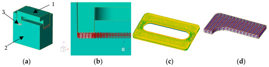
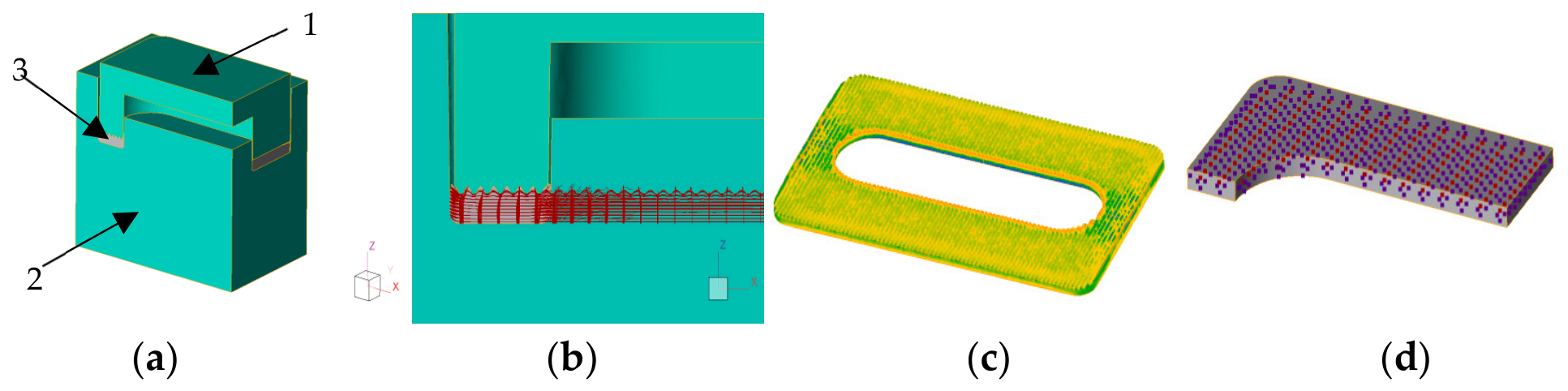
An array of points and lines was created to allow monitoring of the workpiece deformation and material distribution, thus ensuring more precise analysis of the simulation -Figure 2. A three-dimensional grid along X, Y, Z–50, 5, 5, axes was created to aid the visualization of the metal flow’s three-dimensional displacement. The introduction of a grid of discrete points with coordinates X, Y, Z–50, 10, 10, enabled tracking of the parameters during the simulation at every single point.
Figure 2.
(a) 1—tool 1; 2—tool 2; 3—workpiece; (b) three-dimensional crosslinking; (c) distribution of the effective deformations; (d) discrete points.
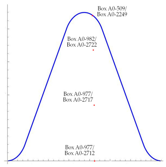
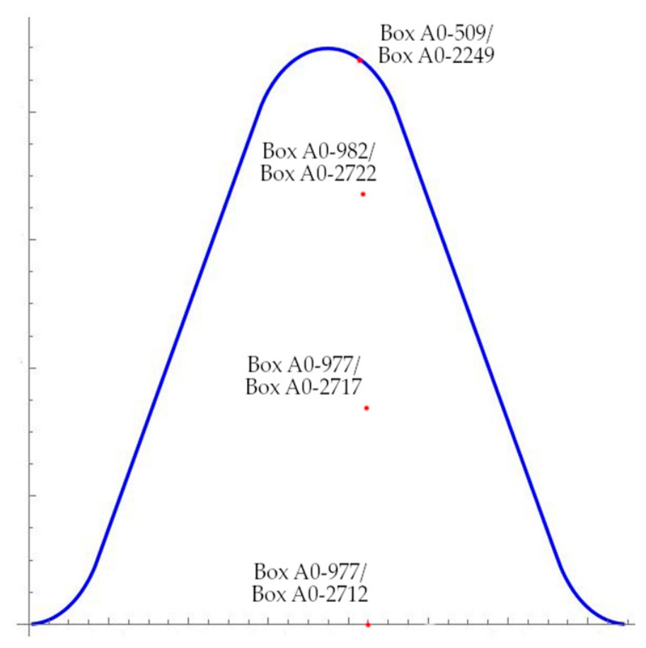
To be able to better analyze the results, we traced some points of the workpiece. Their movement is schematically presented in Figure 3. With their help, we were able to identify and track the deformations during the simulation processes.
Figure 3.
Schematic representation of the used discrete points.
The discrete points enabled us to observe the differences in simulations with and without lubricant and analyze them.
3.1. Plastic Strain–Effective Stress
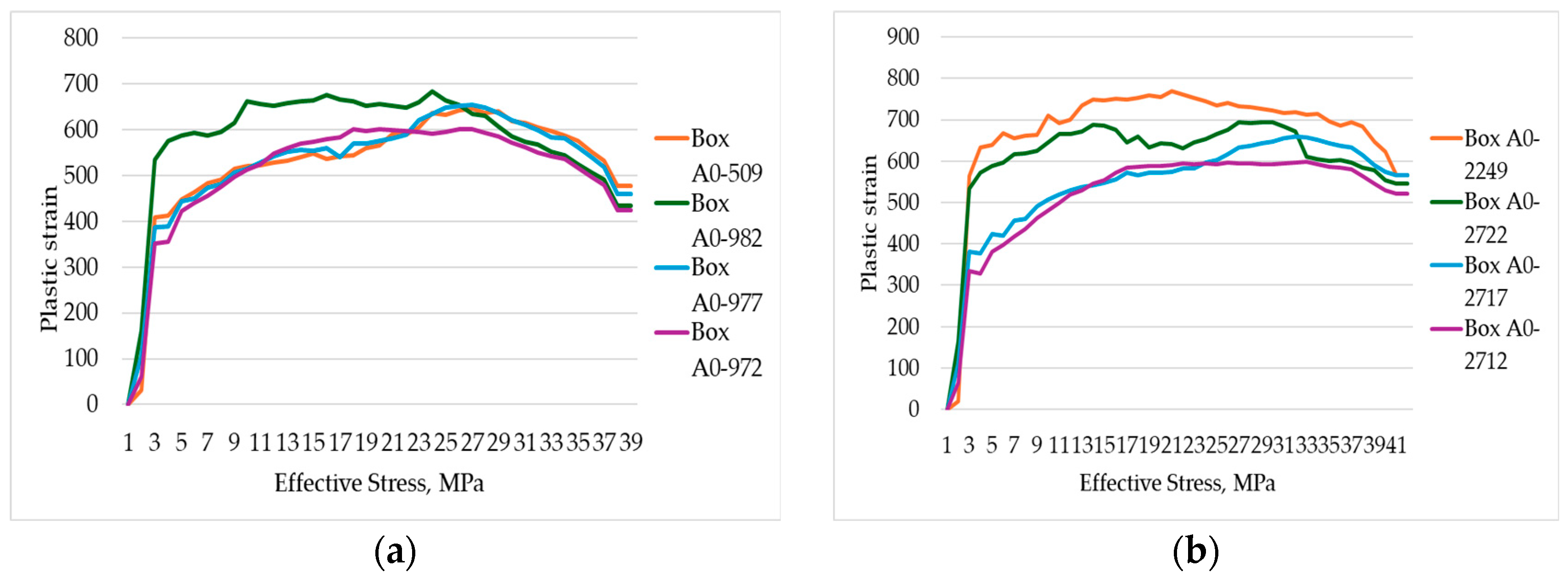
Chart 1 represents stress–strain curves of the selected discrete points during the cold forging process: effective stress—σtr; plastic strain—εtr.
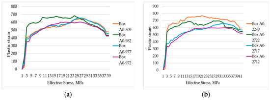
Chart 1.
Effective stress—σtr, plastic strain—εtr, (a) simulation with lubricant, (b) simulation without lubricant.
3.2. Tool Movement (Stroke)
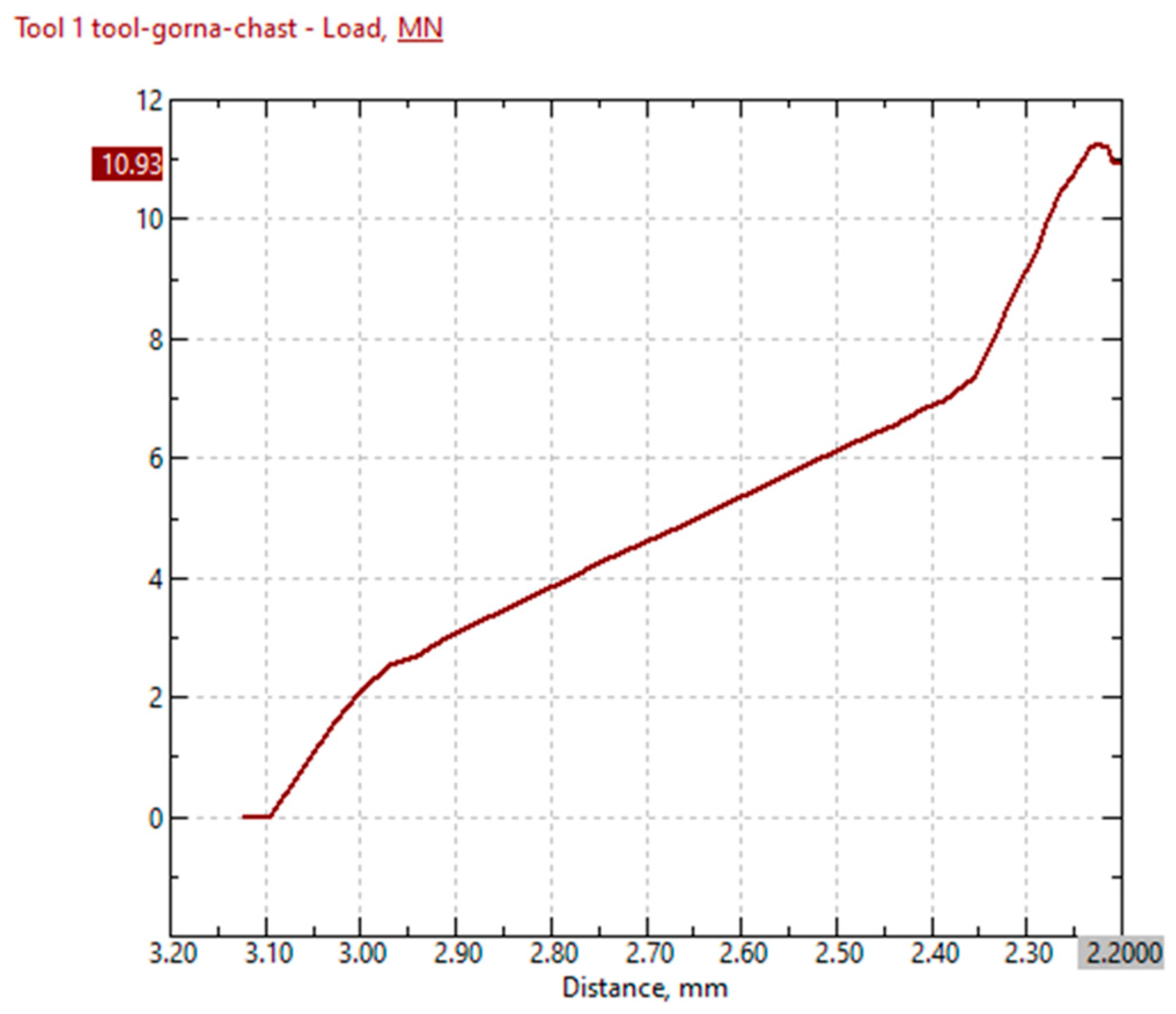
Chart 2 shows the changes in the applied force in relation to the punch movement (stroke). The three main stages in the metal flowing and filling the deformation zone are clearly visible. The first stage is up to 3 mm of the punch stroke. Then, a sharp increase in force is observed, which marks the second stage, at 2.45 mm. During the third stage, the applied force increases slightly, with the increase being more significant at the very end, which is caused by the punch approaching the die.
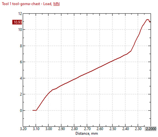
Chart 2.
Tool movement.
3.3. Changes in Temperature
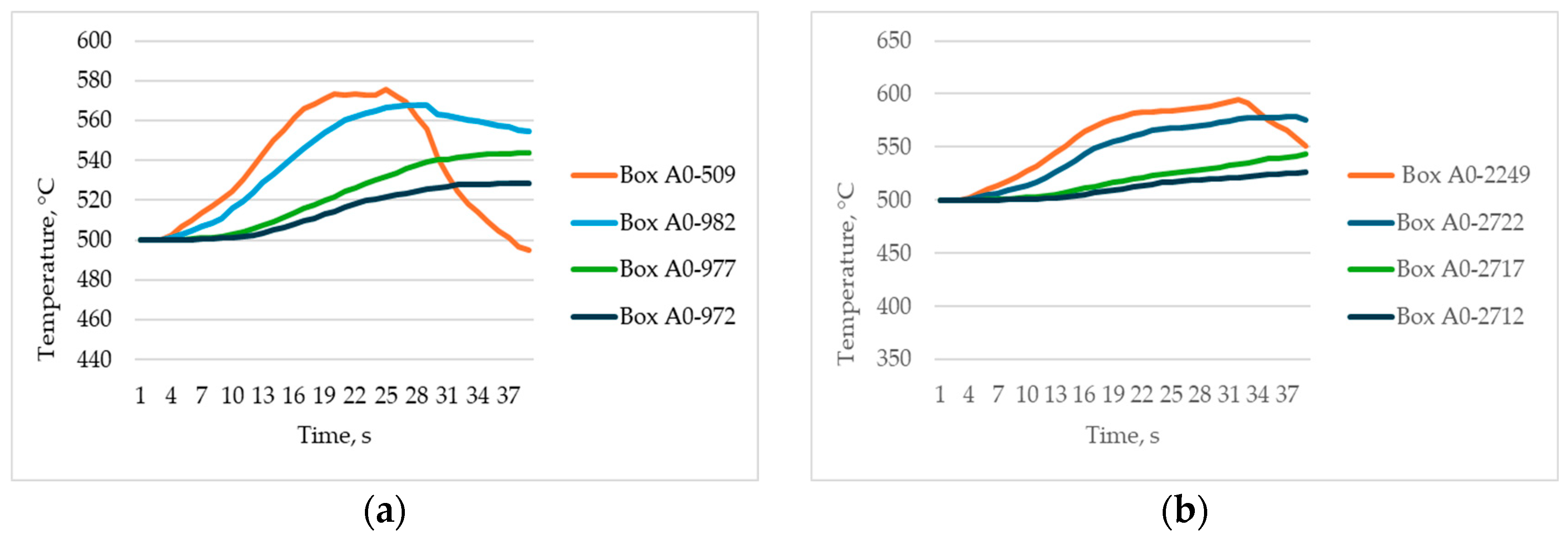
The step-by-step simulation of the closed-die cold forging allowed us to monitor and record the temperature change at every single step of the process. The initial temperature of the workpiece was set in the simulation software to 500 °C.
Chart 3 shows the temperature changes at the set discrete points during the workpiece deformation.
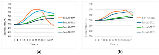
Chart 3.
Time–temperature diagram: (a) Simulation process with lubricant, (b) simulation process without lubricant.
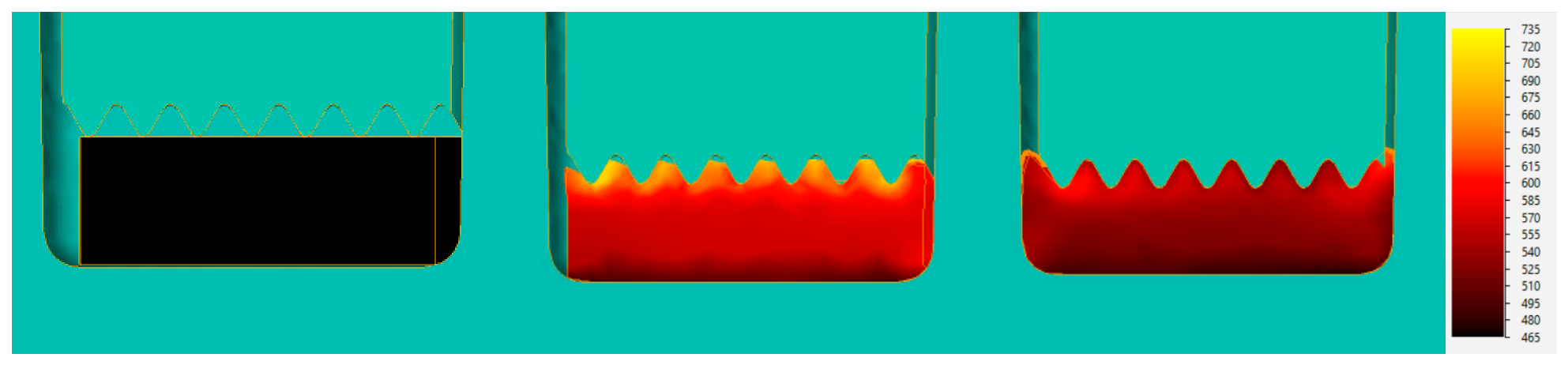
The highest temperature achieved by the deforming workpiece in the absence of lubricant was 721 °C, while the lowest temperature was 465 °C. In the presence of graphite and water, the maximum temperature achieved by the workpiece was 655 °C, while the minimum temperature was 438 °C.
In terms of temperature, 3 distinct stages were observed in the volume closed by the punch and die during the simulation process: initial, intermediate, and final. These are shown in Figure 4.
Figure 4.
Temperature changes during the different stages of deformation.
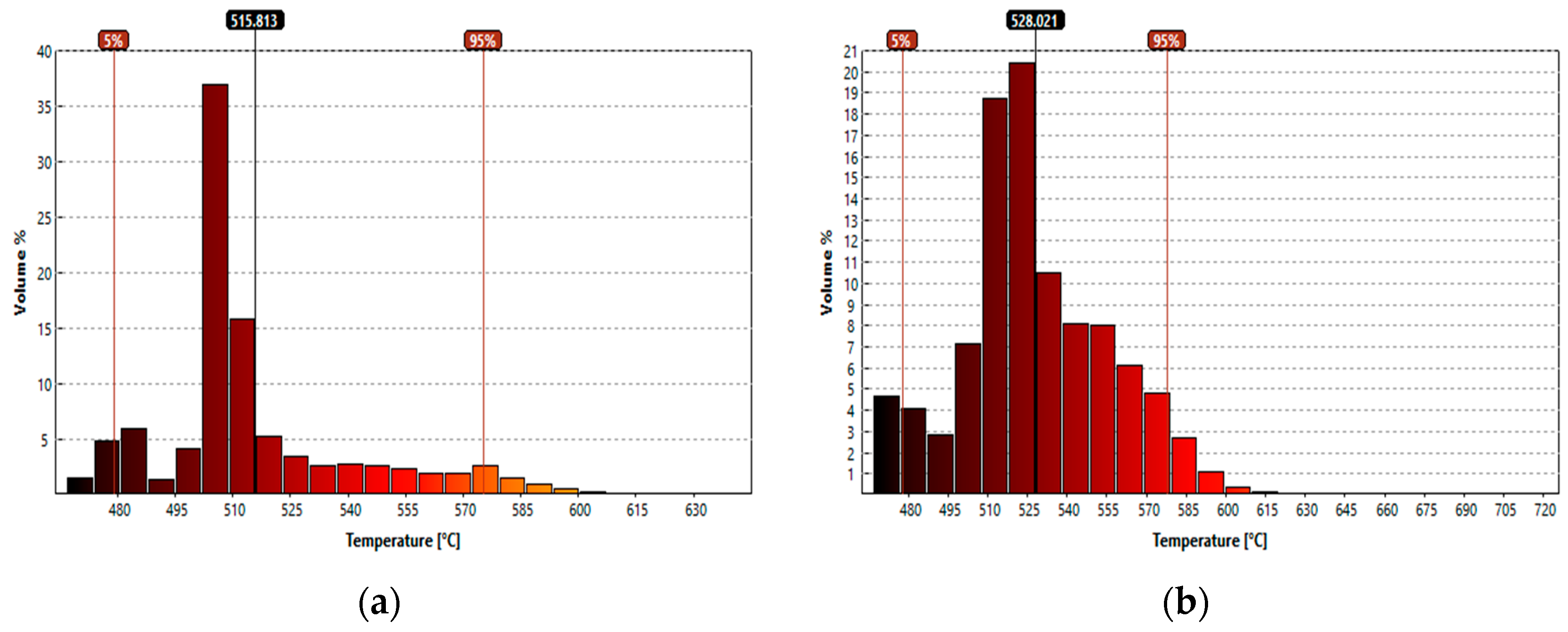
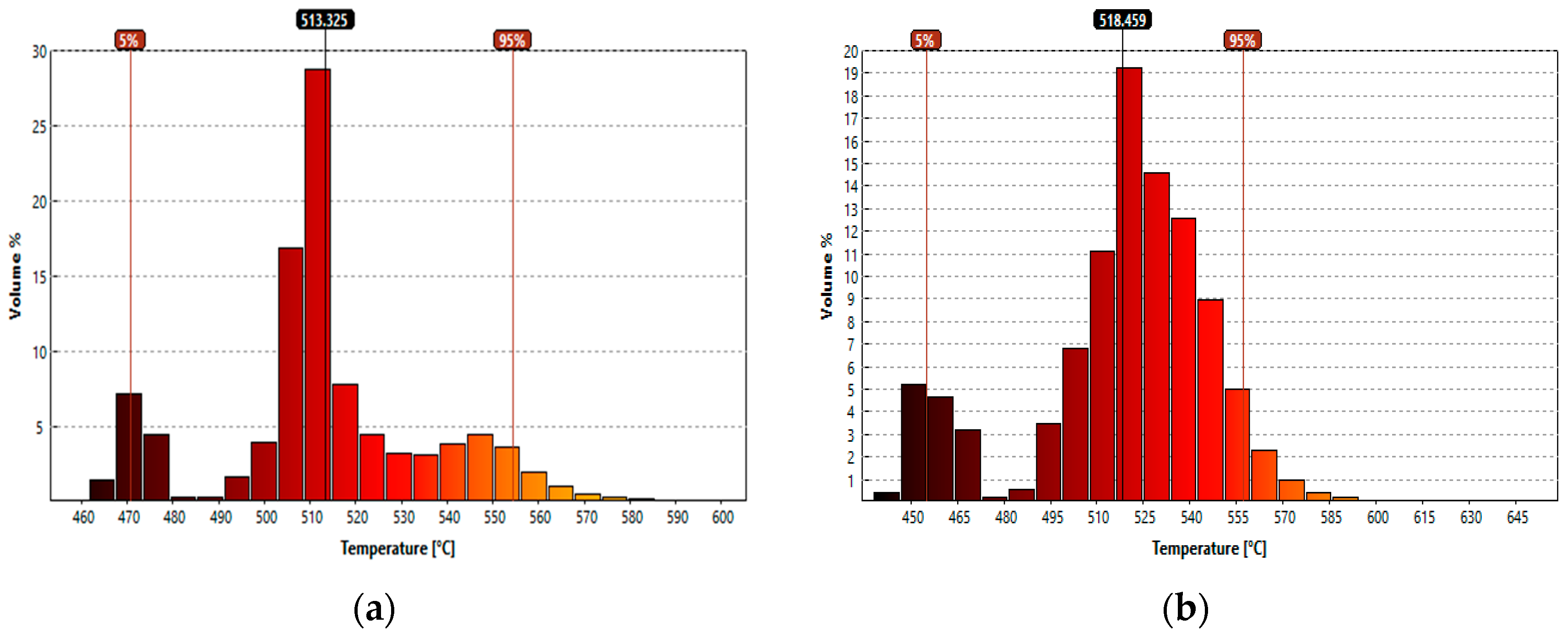
The detailed data on these three stages can be seen on Chart 4 and Chart 5 and in Table 5 and Table 6.
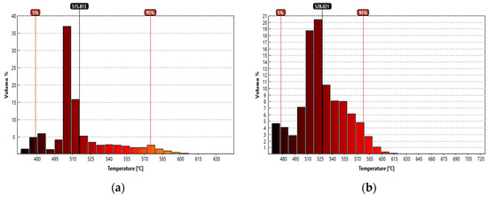
Chart 4.
Volume–temperature diagrams: (a) Workpiece temperature in the intermediate stage of the process, without lubrication; (b) workpiece temperature in the final stage of the process, without lubrication.
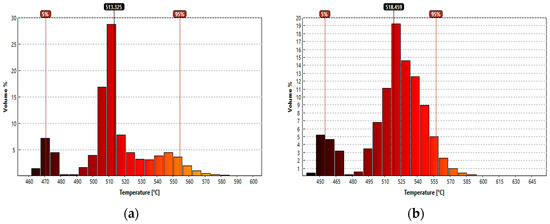
Chart 5.
Volume–temperature diagrams: (a) Workpiece temperature in the final stage of the process, with lubrication; (b) workpiece temperature in the final stage of the process, with lubrication.
Table 5.
Temperature dataset analysis of the deformation without the use of lubricant.
Table 6.
Temperature dataset analysis of the deformation with the use of lubricant (graphite and water).
4. Conclusions
Simulation modelling of the manufacturing of an industrial part made of steel grade S235JR by using a closed-die cold forging process demonstrates the applicability and high accuracy of the simulation carried out by using specialized software applications, such as the QForm professional engineering software for simulation, analysis, and process optimization.
The analysis showed with a high degree of certainty that the simulated cold forging process can be used to manufacture a product made of a particular material. That product would have high quality and performance indicators and would be ready for direct incorporation into other products intended for use by the machine building, automotive, shipbuilding, and other industries without additional processing.
In this sense, the simulation modelling described herein would be very useful for those industrial enterprises that need to analyze and determine the suitability for processing of certain types of materials by the use of closed-die cold forging processes.
Author Contributions
Conceptualization and methodology, A.N.; validation and software, K.K.; drawings and geometric parameters, K.P.; review and editing, A.M. All authors have read and agreed to the published version of the manuscript.
Funding
This research received no external funding.
Institutional Review Board Statement
Not applicable.
Informed Consent Statement
Not applicable.
Data Availability Statement
Data will be available on request.
Acknowledgments
The authors would like to thank the Research and Development Sector at the Technical University of Sofia for financial support.
Conflicts of Interest
The authors declare no conflicts of interest.
References
- Shimanovich, O.A.; Tomilo, V.A.; Mazurenok, A.V.; Belyi, A.N. Cold Forming Technology: A Teaching and Learning Guide for Students of the 1-36 01 05 Specialisation ‘Machines and Technology for the Pressure Processing of Materials’; Belarusian National Technical University: Minsk, Belarus, 2021; pp. 3–8. [Google Scholar]
- Suchkov, A.; Popov, G.; Tomov, B. Manufacture of gear wheels by plastic deformation. [PubMed]
- Hawryluk, M.; Jakubik, J. Analysis of forging defects for selected industrial die forging processes. Eng. Fail. Anal. 2016, 59, 396–409. [Google Scholar] [CrossRef] [Scilit]
- Bay, N. New lubricant systems for cold and warm forging–advantages and limitations. In Proceedings of the 12th International Cold Forging Congress, Stuttgart, Germany, 1 January 2011. [Google Scholar]
- Hirscvogel, M.; Dommelen, H.V. Some applications of cold and warm forging. J. Mater. Process. Technol. 1992, 35, 343–356. [Google Scholar]
- Colin, S.H. A review of automation in manufacturing illustrated by a case study on mixed-mode hot forging. Manuf. Rev. 2014, 15, 1–14. [Google Scholar]
- Bay, N. New tribo-system for cold forging of steel, stainless steel and aluminum alloys. In Proceedings of the 46th ICFG Plenary Meeting, Paris, France, 15 September 2013; pp. 171–178. [Google Scholar]
- Shirgaokar, M. Forging Processes: Variables and Descriptions. In Cold and Hot Forging: Fundamentals and Applications; Altan, T., Ngaile, G., Shen, G., Eds.; ASM International: Novelty, OH, USA, 2005; pp. 7–15. [Google Scholar] [CrossRef] [Scilit]
- Shirgaokar, M.; Ngaile, G. Plastic Deformation: Strain and Strain Rate. In Cold and Hot Forging: Fundamentals and Applications; Altan, T., Ngaile, G., Shen, G., Eds.; ASM International: Novelty, OH, USA, 2005; pp. 17–23. [Google Scholar] [CrossRef] [Scilit]
- Bansod, P.P.; Tidke, D.J. Designing A Forging Die for Hanger Bolt using CAD. Int. J. Anal. Exp. Finite Elem. Anal. (IJAEFEA) 2015, 2, 64–66. [Google Scholar]
- Dimova, D. Investigation of the Microstructure, Mechanical and Deformation Characteristics of C60 Steel after Quenching and Tempering—Part I. In Proceedings of the Youth Forum “Science, Technology, Innovation, Business” 2023 (Autumn), Plovdiv, Bulgaria, 26–27 November 2023; House of Science and Technology: Plovdiv, Bulgaria, 2023; pp. 90–99. [Google Scholar]
- A 681–08; Standard Specification for Tool Steels Alloy. ASTM Internationa: West Conshohocken, PA, USA, 2022.
- Shivpuri, R.; Satish, K. Lubricants and Their Applications in Forging. In Metalworking: Bulk Forming; ASM International: Novelty, OH, USA, 2005; Volume 14A. [Google Scholar]
- Tomov, B. Technology and Tooling for Metal Working by Plastic Deformation, Textbook for Students at VIMMES-Ruse, Part 1. 1981; 172, p. 59.
- Jarfors, A.E.; Castagne, S.J.; Danno, A.; Zhang, X. Tool wear and life span variations in cold forming operations and their implications in microforming. Technologies 2016, 5, 3. [Google Scholar]
- Lange, K.; Cser, L.; Geiger, M.; Kals, J.A.G. Tool Life and Tool Quality in Bulk Metal Forming. CIRP Ann–Manuf. Technol. 1992, 41, 667–675. [Google Scholar] [CrossRef] [Scilit]
- Ngaile, G.; Saiki, H.; Ruan, L.; Marumo, Y.A. Tribo-testing method for high performance cold forging lubricants. Wear 2007, 262, 684–692. [Google Scholar]
- Scapin, M.; Verleysen, P.; Hokka, M. Temperature Dependence of Material Behaviour at High Strain-Rate. J. Dyn. Behav. Mater. 2019, 5, 197. [Google Scholar] [CrossRef] [Scilit]

Disclaimer/Publisher’s Note: The statements, opinions and data contained in all publications are solely those of the individual author(s) and contributor(s) and not of MDPI and/or the editor(s). MDPI and/or the editor(s) disclaim responsibility for any injury to people or property resulting from any ideas, methods, instructions or products referred to in the content. |
© 2026 by the authors. Licensee MDPI, Basel, Switzerland. This article is an open access article distributed under the terms and conditions of the Creative Commons Attribution (CC BY) license.