


Abstract
Optical interference structures (OISs) are of particular interest due to their attractive potential for use in many practical applications involving laser light. They have many interesting properties, including the ability to smoothly tune the wavelength of the incident laser beam, simple implementation of the elements and the absence of electrical and magnetic influences. Here, the focus is on a new theoretical approach to the action of OIS, based on our newly introduced multi-layer interference wedge structure, which improves the reflection and transmission characteristics of the classical single-gap interference structure. This new approach is based on multi-beam interference and the implementation of the parallel algorithm programming principle.
1. Introduction
Optical interference structures (OISs) have traditionally been of interest due to their potential use in many practical applications based on optical radiation (laser light). Such structures have applications in optical communications, optical beam splitters, remote contactless measurements, controlling the displacement of small objects, optical metrology and scientific research. This potential is due to their extremely interesting properties. Notably, the use of OIS offers the advantage of avoiding the influence of external magnetic and electric fields, in addition to being simple. OISs also have the useful advantage of enabling the wavelength of the incident laser beam to be smoothly tuned, which is important for many applications. The appropriate treatment of OIS is the subject of continuous research and development [1,2,3].
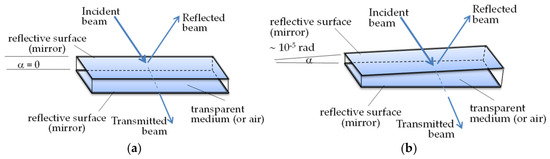
The base of the OIS is the well-known Fabry–Pérot interferometer (FPI) [4] and its variant, the interference wedge structure (IWS). The FPI structure and IWS have a similar construction (Figure 1): two reflective surfaces (mirrors) form a gap in which air or another transparent material (such as glass or sapphire) is placed. The mirrors in the FPI are practically perfectly parallel. In the IWS, where the gap is a Fizeau interferometer or interference wedge (IW), the mirrors are placed at a very small angle (~10−5 rad). However, this angular difference between the two structures leads to significant differences in their properties. Both interferometers work on the basis of multi-beam interference. The properties of the FPI are well known due to its importance in a number of optical measurements [4]. The basic properties of the IW, a single-gap IWS, have not been studied as extensively in terms of diversity and applicability.
Figure 1.
(a) Fabry–Perot interferometer (FPI): two plane-parallel partially reflecting mirrors with a transparent medium between them. (b) Single-gap interference wedge structure (IWS): two reflecting mirrors at a small apex angle with a transparent medium between them.
Interest in IWSs is increasing in connection with their prospective application in laser technology. We have experience in studying the properties of IWSs and their application in a number of laser solutions, for example a new solution for single-mode, two-wavelength lasers using spectrally selective, non-Snell’s reflection and transmission asymmetry [1,2,3,4,5]. The next stage in the development of IWSs is the new structure introduced by us: the combined interference wedged structure (CIWS) [6], which is a further development of Fizeau-type optical interferometry. The CIWS uses a multi-dielectric layer to provide narrow spectral selection (~0.01 nm) and a wide tuning range (>10–50 nm) simply by sliding the CIWS [7]. A properly assembled CIWS system comprising two or more IWSs can effectively provide a large, linear change in the transmission of an incident laser beam simply by sliding the CIWS, forming the basis of our competitive beam splitters, particularly for powerful laser beams [8,9].
2. Principle of Theoretical Description
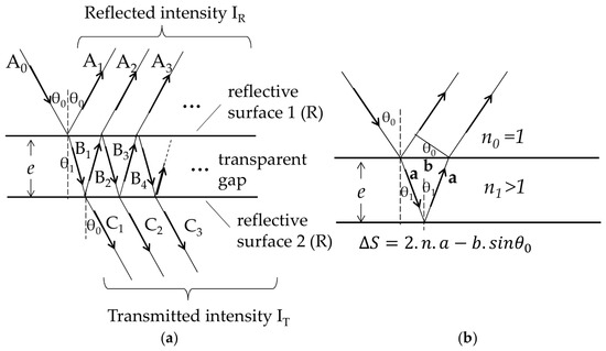
In order to describe the operation of different types of OIS theoretically, many theoretical models based on the wave representation of optical radiation have been developed [2,3,4], or the description has been simplified to validate practical experiments. In this paper, we focus on a new theoretical approach to describing the operation of OIS using our recently introduced multilayer interference wedged structure. We continue to develop techniques and methods to improve the characteristics of such structures. Our new approach is based on the classical representation of multi-beam interference but is implemented using the principle of parallel algorithm programming. This approach is illustrated by the model in Figure 2. According to the classical description, in multi-beam interferometers, such as FPIs, partial waves are produced by multiple reflections and refractions at plane surfaces, and their amplitude decreases with the increasing number of reflections/refractions (Figure 2a).
Figure 2.
(a) General approach for obtaining the reflected and transmitted beams in the case of an FPI multi-beam interferometer. (b) Determining the phase shift between two adjacent partial beams in an FPI.
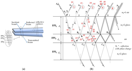
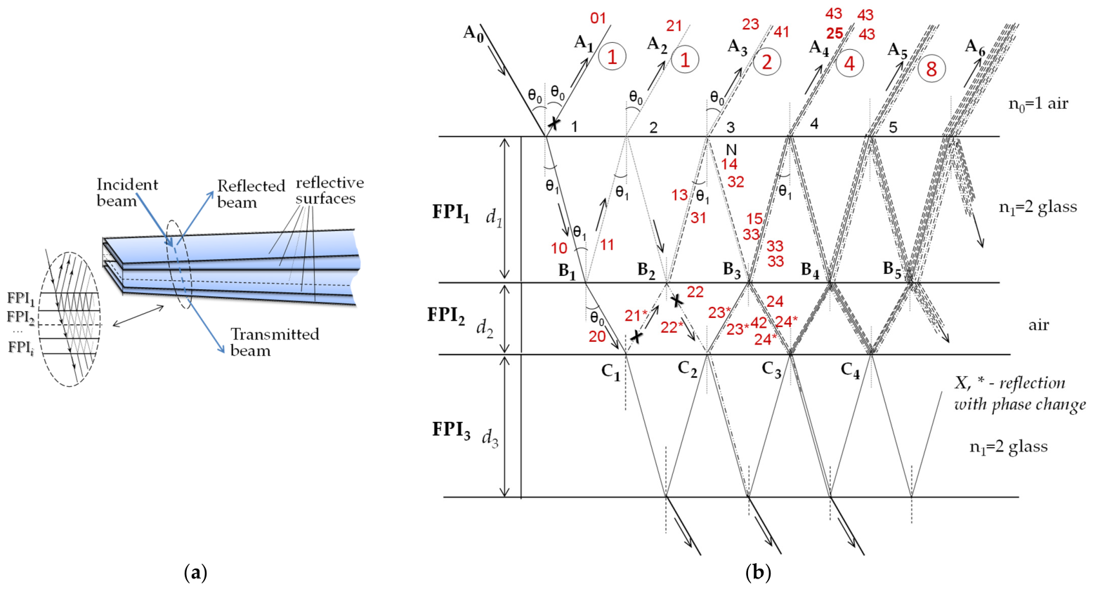
At each boundary surface, the wave (hereafter referred to as a ‘beam’) splits into two parts: one that is refracted and one that is reflected, in accordance with the transmission/reflection properties of the corresponding boundary surface. It should be noted that Figure 3 only shows the propagation directions of the partial waves.
Figure 3.
(a) An optical interference wedge structure consisting of i-layers, with the inset showing the schematic directions of the partial beams between the reflective surfaces. (b) A detailed schematic representation of the formation and propagation of partial beams from an incident optical beam (laser), and the formation of the resultant reflected and transmitted beams for a three-layer optical interference structure. At the point of incidence of the initial beam, the pattern can be considered to consist of three superimposed Fabry–Pérot interferometers. Note: Partial beams that undergo a π phase shift upon reflection are marked with an asterisk (*) in their superscript and indicated with an ‘X’ symbol in the schematic.
The incident beam is described by the following complex expression:
where is the initial amplitude of the incident beam, ω = 2πc/λ, λ is the wavelength, c is the speed of light, k is the wave vector and t is the time parameter and x is the spatial coordinate. If R denotes reflection at the boundary surface (with both surfaces considered equal), the corresponding amplitudes of the partial beams are defined as follows:
The reflected and transmitted beams are obtained by summing the amplitudes … in the reflection direction and … in the transmission direction, taking into account the reflection/refraction coefficients of the boundary surfaces. The intensities of the reflected and transmitted rays are then determined by summing them up. Using wave theory, the following expressions are obtained for an infinite number of partial beams [4]:
with the phase shift determined by
where ∆S = 2.n.e.cosθ1, the difference in optical paths between two adjacent partial beams, as shown in Figure 2b below the scheme.
By superimposing several single-gap IWs with common separating reflective surfaces, we can create a multilayer composite interferometric structure. We have introduced such structures and demonstrated that they exhibit enhanced properties that make them highly relevant for practical applications. Initially, we started with simplified theoretical descriptions to demonstrate the functionality of this complex structure. However, a more rigorous theoretical analysis has proven to be a complex and time-consuming task that requires significant resources. In this study, we aim to analyze this type of interference structure using the capabilities of parallel programming.
In our modelling approach, we use a similar description to that used for a single-gap FPI to describe incident beam splitting at a boundary surface, but now in the case of two or more structures. Due to the very small size of the incident beam and the small angle at the tip of the wedged structure, the structure at the point of incidence of the beam can be considered a series of superimposed FPIs. Figure 3a shows a schematic representation of splitting beams in a multilayer interference wedged structure. Figure 3b shows an enlarged view of the incidence area on the front reflective surface of the OIS, which consists of two or more layered wedged structures. At each boundary surface of the OIS, the incoming partial beam splits into two parts: reflected and transmitted.
The total amplitude A of the reflected beam (the same applies to the passing resultant beam) is obtained by summing all the partial amplitudes Ai at points 1, 2, 3, 4, 5, and so on. The number of partial beams reaching each of these points increases in accordance with the number of reflections and refractions undergone by the original incident beam. For two layers (two interference structures), the number of partial beams at these points is 1, 1, 2, 4, 8, 16, 32, …, as shown by the circled numbers. When a third structure is added, the number of partial beams increases significantly. As can be seen, a structure consisting of two or more interfering substructures becomes very complex. Therefore, we need to implement an efficient algorithm for calculating the total amplitude of reflected and transmitted beams. In order to develop this algorithm, we must take into account the numerous partial beams generated through multiple reflections and refractions. CUDA (Compute Unified Device Architecture) [10] enables us to utilise the parallel processing capabilities of NVIDIA GPUs, making it ideal for this computationally intensive task. The NVIDIA CUDA Toolkit (version 12.4.1 [11]) is used to set up the parallel computing framework. Different values for refraction and reflection are stored in global variables within the GPU memory. Calculations for each layer may be performed by one or more threads.
3. Mathematics: Explanation of Parallel Algorithm
This pseudo-algorithm outlines the basic steps required to simulate refraction and reflection calculations in interferometric structures using parallel computing techniques.
- Initialization:
- Initialize the physical parameters (refractive indices, layer thicknesses and angle of incidence).
- Memory Allocation:
- Allocate memory on the device for the following variables: amplitudes, phases and result storage.
- Compute Amplitudes and Phases:
- Launch the kernel to compute the amplitudes and phases of the partial beams passing through each layer.
- Parallel Simulation:
- Use the parallel reduction technique to sum the amplitudes of the partial beams.
- Execution Flow:
- Initialize and transfer data between the host and the device.
- Launch the kernels for computation.
- Retrieve the results from the device and display them.
In order to parallelize the calculation of the refraction and reflection of beams in different layers, we first define the refractive indices, layer thicknesses and angles of incidence. Using CUDA’s memory hierarchy [11], we store the input parameters (refractive indices, thicknesses and angles), the beam data (amplitudes and phases) and the results. Next, a CUDA kernel computes the propagation of each beam through the layers. We propose two algorithms to evaluate the execution power of the simulation for interferometric structures. Parallelism is achieved by assigning each thread to handle either a distinct beam or a distinct layer, depending on the chosen algorithm. Effective thread and block management is employed to parallelize the computation of amplitudes and phases through different layers. We efficiently sum results across threads or blocks using parallel reduction techniques within CUDA kernels. Further optimizations consider memory access patterns and kernel configurations (block size and grid size), which are tailored to our specific GPU architecture and problem size. The initial optimization technique uses CUDA’s memory hierarchy [12,13] to enhance the performance of the algorithm, making use of the strengths of constant, shared and global memory. Constant memory is allocated for refractive values and thicknesses as these remain unchanged during kernel execution, thus optimizing access efficiency over global memory. Shared memory is used within kernel functions for block-level reductions, which are significantly faster than global memory operations. Furthermore, CUDA’s warp-level parallelism enhances the parallel execution of our simulation by exploiting the synchronized execution of threads within a warp. The following steps outline the CUDA simulation of interferometric structures, emphasizing warp-level parallelism: One hypothetical function and its description are given below:
- Warp-Level Parallelism: The ‘warpReduceSum’ function performs a reduction at warp level to sum the amplitudes within each warp. It uses warp intrinsic (__shfl_down_sync) for this purpose.
- Kernel ‘computePartialBeams’: This kernel computes the amplitudes and phases for each partial beam.
- Kernel sumAmplitudes: This kernel uses warp-level parallel reduction to sum the amplitudes of partial beams within each warp and then uses atomicAdd to accumulate the results from each warp.
- Main Function: As before, the main function initializes parameters, allocates memory, launches kernels and retrieves the results.
This enhanced algorithm uses warp-level parallelism to optimize amplitude reduction, thereby improving simulation performance.
4. Conclusions
In this paper, we present a new approach to the theoretical simulation of the reflection and transmission characteristics of a complex optical interference wedge structure composed of multiple optical interference structure (OIS) elements to improve their performance. Such a complex OIS is described using an approach based on a simple, single-gap Fabry–Perot interferometer placed in series with others. CUDA was used to develop a parallel algorithm to achieve this goal.
Author Contributions
Conceptualization, M.D. and M.M.; methodology, M.D.; validation, M.D. and M.M.; formal analysis, M.D.; investigation, M.D. and M.M.; resources, M.D.; data curation, M.D.; writing—original draft preparation, M.D. and M.M.; writing—review and editing, M.D. and M.M.; visualization, M.D.; supervision, M.D.; project administration, M.D. and M.M.; funding acquisition, M.D. All authors have read and agreed to the published version of the manuscript.
Funding
This research received no external funding.
Institutional Review Board Statement
Not applicable.
Informed Consent Statement
Not applicable.
Data Availability Statement
The data presented in this study are available within the article.
Acknowledgments
The authors would like to thank the Scientific Laboratory “Optical and Quantum Electronics” and the Centre of Competence “Intelligent Mechatronic, Eco- and Energy-Saving Systems and Technologies” (IMEESST), Contract No. BG16RFPR002-1.014-0005, Lab. C8-4 “Optical and Laser Technologies in the Automotive Industry”, for providing the opportunity to achieve the goal of this research.
Conflicts of Interest
The authors declare no conflict of interest.
References
- Nenchev, M.; Stoykova, E. Interference wedge properties relevant to laser applications: Transmission and reflection of restricted light beams. Opt. Quantum Electron. 1993, 25, 789–799. [Google Scholar] [CrossRef] [Scilit]
- Stoykova, E.; Nenchev, M. Gaussian beam interaction with an air-gap Fizeau interferential wedge. J. Opt. Soc. Am. A 2010, 27, 58–68. [Google Scholar] [CrossRef] [Scilit] [PubMed]
- Stoykova, E.; Nenchev, M.; Sainov, V. Optical Elements and Systems in Laser Technique and Metrology. Analysis and Modeling; LAP-Lambert Academic Publishing: Saarbrücken, Germany, 2012; p. 225. [Google Scholar]
- Demtröder, W. Laser Spectroscopy. Basic Principles, 4th ed.; Springer: Berlin/Heidelberg, Germany, 2008. [Google Scholar]
- Stoykova, E.; Nenchev, M. Strong optical asymmetry of an interference wedge with unequal-reflectivity mirrors and its use in unidirectional ring laser designs. Opt. Lett. 1994, 19, 1925–1927. [Google Scholar] [CrossRef] [Scilit] [PubMed]
- Nenchev, M.; Stoykova, E.; Deneva, M. Composite wavelength tunable wedged interference structures with increased free spectral range. Opt. Quantum Electron. 2018, 50, 433. [Google Scholar] [CrossRef] [Scilit]
- Deneva, M.; Nenchev, M. Utilization of Pure Glass Composite Interference Wedged Structures as Highly Efficient Light Beam Splitters. In Proceedings of the 2022 XXXI International Scientific Conference Electronics—ET2022, Sozopol, Bulgaria, 13–15 September 2022; pp. 1–6. [Google Scholar] [CrossRef] [Scilit]
- Nenchev, M.; Deneva, M. Interference Wedged Structure for Remote and Purely Optical Intensity Control of a Powerful Laser Beam with a Low-Intensity Light. In Proceedings of the XXXI International Scientific Conference Electronics—ET2022, Sozopol, Bulgaria, 13–15 September 2022; pp. 1–5. [Google Scholar] [CrossRef] [Scilit]
- Deneva, M.; Nenchev, M.; Marinova, M. Light Beam Splitters Based on Complex Multi-Interference Wedged Structures that Use Only Components with Fresnel’s Reflection. In Proceedings of the XXXI International Scientific Conference Electronics—ET2022, Sozopol, Bulgaria, 15–17 September 2021; pp. 1–6. [Google Scholar] [CrossRef] [Scilit]
- Bonaccorso, F.; Lauricella, M.; Montessori, A.; Amati, G.; Bernaschi, M.; Spiga, F.; Tiribocchi, A.; Succi, S. LBcuda: A high-performance CUDA port of LBsoft for simulation of colloidal systems. Comput. Phys. Commun. 2022, 277, 108380. [Google Scholar] [CrossRef] [Scilit]
- CUDA Toolkit Release Notes (v12.4.1), NVIDIA. Available online: https://developer.nvidia.com/cuda-toolkit-archive (accessed on 15 April 2024).
- Kim, J.; Eom, H.; Kim, Y. Analyzing Data Locality on GPU Caches Using Static Profiling of Workloads. IEEE Access 2023, 11, 95939–95947. [Google Scholar] [CrossRef] [Scilit]
- Lal, S.; Varma, B.S.; Juurlink, B. A Quantitative Study of Locality in GPU Caches for Memory-Divergent Workloads. Int. J. Parallel Prog. 2022, 50, 189–216. [Google Scholar] [CrossRef] [Scilit]
Disclaimer/Publisher’s Note: The statements, opinions and data contained in all publications are solely those of the individual author(s) and contributor(s) and not of MDPI and/or the editor(s). MDPI and/or the editor(s) disclaim responsibility for any injury to people or property resulting from any ideas, methods, instructions or products referred to in the content. |
© 2026 by the authors. Licensee MDPI, Basel, Switzerland. This article is an open access article distributed under the terms and conditions of the Creative Commons Attribution (CC BY) license.