


Abstract
The assessment of safety against derailment is a mandatory procedure according to EN 14363:2019. Since practical on-track tests are accompanied by significant difficulties and high costs, current regulations allow the use of validated calculation methods. To introduce an objective assessment, the author applies the theoretical “Horizontal Dynamic Passport” approach to investigate three-axle bogies. The study analyzes the influence of the rigid wheelbase on lateral interaction forces across a wide range of radii. The results demonstrate that the wheelbase length significantly affects the forces in the middle and trailing wheelsets, often altering the kinematic guiding mode. These findings provide objective criteria for defining operational limits and ensuring stability according to Nadal’s criterion.
1. Introduction
The methods for assessing safety against derailment for the acceptance of new freight wagons are mostly performed using a combination of testing and theoretical mathematical calculations or simulations. With the constant pressure on the railway industry to improve efficiency by increasing load capacities—often achieved through the use of three-axle bogies—the verification of safety becomes increasingly complex. Increasing the axle load or the rigid wheelbase requires rigorous assessment to prevent infrastructure degradation and derailment risks [1]. Most assessment methods are based on dynamic tests performed under representative service conditions using defined track characteristics and statistical assessment methods. All test types have their advantages and disadvantages, as described in [2].
Theoretical mathematical calculations have a long tradition in rail vehicle dynamics, starting from the fundamental works of Nadal [3], who established the derailment criterion (Y/Q) still applied today in international normative documents like EN 14363:2019 [4]. While experimental measurement of parameters such as lateral forces (Y) and vertical loads (Q) remains a standard procedure for approving new freight wagons, the practical implementation of these tests for three-axle bogies is accompanied by significant difficulties. These include finding a track with a specific radius to provoke the worst-case scenario for the middle wheelset, ensuring free access to railway infrastructure, and managing high logistical costs. For wagon manufacturers, these difficulties translate into long-term approval procedures and higher expenses.
To mitigate these challenges, manufacturers often attempt to avoid full dynamic tests by utilizing the provisions of EN 14363:2019 [4] and EN 16235:2013 [5]. These standards allow for the acceptance of a new vehicle if it can be demonstrated that its parameters relate closely to those of an approved “reference wagon.” However, proving the “convergence” of parameters between a new three-axle bogie design and an existing reference vehicle is a lengthy, complex, and often subjective process. This is particularly true when modifying geometric parameters like the rigid wheelbase (2l), which drastically alters the kinematic behavior in curves.
According to “Method 2” of EN 14363:2019 [4], numerical simulations or calculations can be used for assessment. However, the standard does not explicitly specify which theoretical method should be used, provided the results are reliable. For three-axle bogies, the challenge lies in the redistribution of guiding forces between the leading (Y1), middle (Y2), and trailing (Y3) axles. As noted in [6,7], the middle wheelset in a three-axle configuration is subject to specific constraints in tight curves (R < 150 m), where the “guiding force” and “lateral force” mechanisms differ from standard two-axle bogies.
Existing research often focuses on dynamic simulations of specific bogie types, such as the ELH3 or locomotive bogies [6,8], or on general derailment factors [9]. However, there is a lack of a systematic, objective theoretical method that allows manufacturers to quickly assess how changes in the wheelbase (2l) affect the safety envelope without resorting to expensive physical prototyping. From the perspective of the wagon manufacturers, the used method must be objective, fast, and capable of delivering reliable results to satisfy the notified bodies.
This work introduces an objective theoretical method—the Horizontal Dynamic Passport (HDP)—to assess safety against derailment, based on the methodology developed in [2]. By applying this method, it is possible to compare the safety parameters of different wheelbase configurations (3.0 to 4.0 m) and shorten the time and costs of the approval procedure in accordance with [4]. The necessity of such detailed theoretical analysis for three-axle running gear is further supported by [7], where the resistance against derailment for the ChME3 locomotive in small-radius curves was investigated. That study highlighted that in tight curves, the lateral interaction forces are highly sensitive to geometric parameters, necessitating precise optimization to prevent flange climbing. Building on these premises, the results obtained from the theoretical analyses in this work demonstrate the critical influence of the wheelbase on the force distribution (Y1, Y2, Y3) and provide a validated approach for demonstrating compliance with the safety criteria.
2. Materials and Methods
2.1. Object of Study: Three-Axle Bogie Configuration
The research focuses on three-axle bogie design intended for freight wagons. The key geometric variable in this study is the rigid wheelbase (2l), defined as the distance between the first and the third axle. Four distinct configurations were modeled: 2l = 3.0 m, 3.4 m, 3.6 m, and 4.0 m.
The fixed parameters used in the calculations are:
- Axle load (2p0): 22.5 t (per axle);
- Wheel diameter (D): 920 mm;
- Distance between rolling circles (2s): 1500 mm;
- Friction coefficient wheel-rail (μ): 0.25.
2.2. Methodology for Horizontal Dynamic Passport (HDP) Calculations
To theoretically assess the interaction forces and safety against derailment, a specialized methodology for developing a “Horizontal Dynamic Passport” (HDP) for a three-axle bogie was employed. This approach is based on the quasi-static equilibrium of the bogie while negotiating a curve and considers all possible geometric positions the bogie can assume.
Unlike two-axle bogies, the curving kinematics of three-axle configurations are more complex due to the presence of a middle wheelset. The methodology defines four primary positions, which are decisive for the generation of lateral forces.
2.2.1. Bogie Positions in Curve
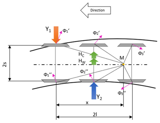
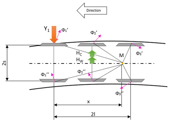
Case 1: Inscription with Guiding Middle Wheelset (Position 1). The first examined variant is the position of maximum skewing, where the wheel flange of the first (attacking) wheelset contacts the outer rail, and the wheel flange of the second (middle) wheelset contacts the inner rail of the curve. This configuration is characteristic of curves with small radii, where the geometric versine of the curve exceeds the lateral play of the middle wheelset.
The force scheme and geometric position for this case are presented in Figure 1.
Figure 1.
Position of maximum crossing: Contact at the first (outer rail) and second (inner rail) wheelsets.
In Figure 1, the solid curved lines represent the rails, the dash-dotted line denotes the longitudinal centerline of the bogie, and the thin dashed lines indicate the geometric construction lines connecting the wheel–rail contact points to the instantaneous center of rotation M.
In this position, the equilibrium of forces is determined by the interaction between the centrifugal force, the friction forces (Φi), and the reactive guiding forces (Y1 and Y2) arising at the contact points.
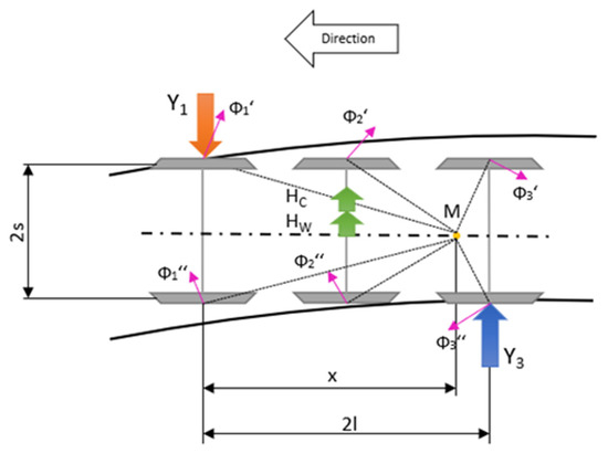
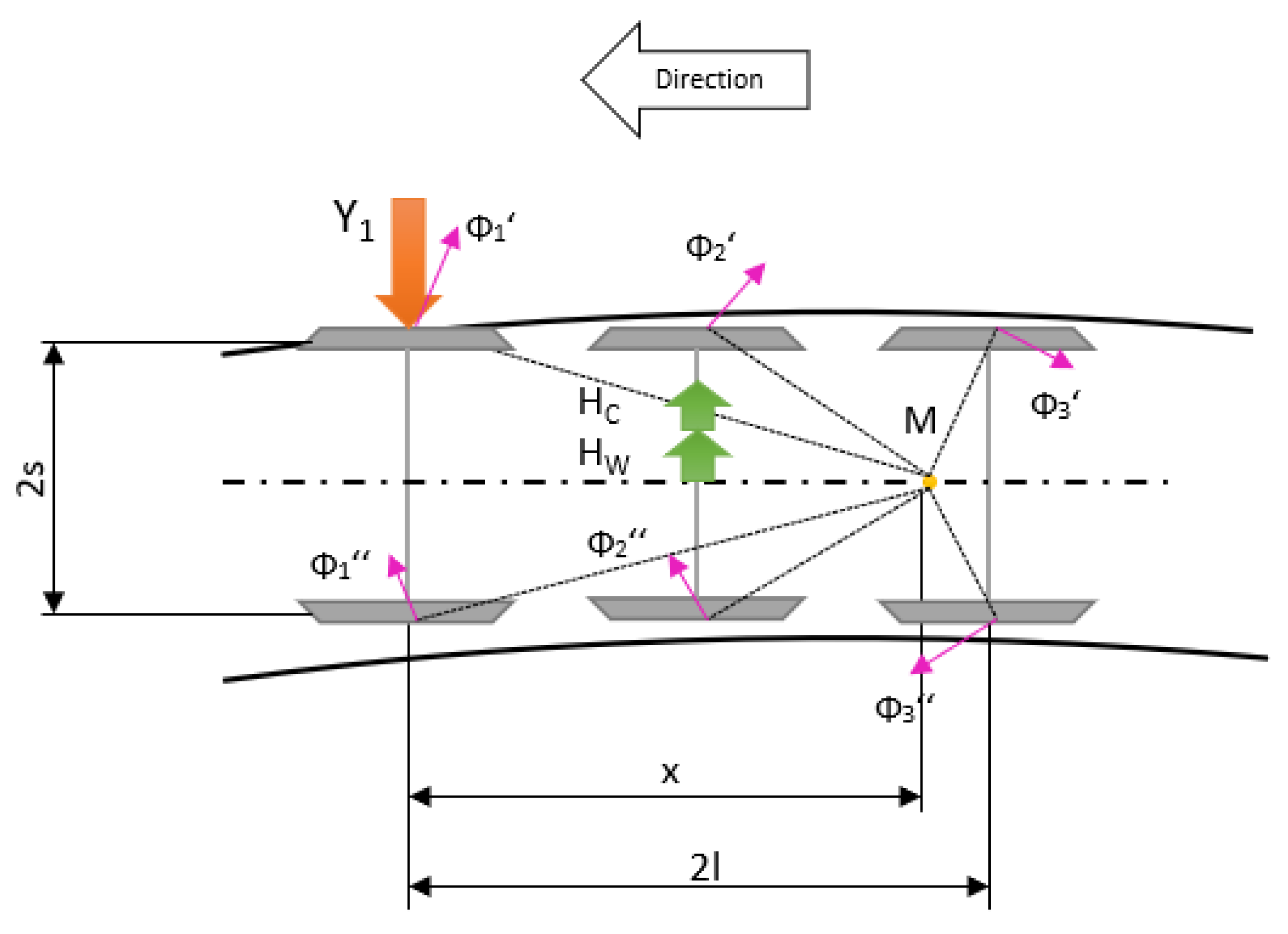
Case 2: Inscription with Guiding Trailing Wheelset (Position 2). The second possible position of maximum skewing occurs when the wheel flange of the first (attacking) wheelset contacts the outer rail, and the wheel flange of the third (trailing) wheelset contacts the inner rail. This scenario is observed in curves with larger radii, where the middle wheelset moves freely (without flange contact) or when the wheelbase dimensions allow such inscription.
The scheme for this case is shown in Figure 2.
Figure 2.
Position of maximum crossing: Contact at the first (outer rail) and third (inner rail) wheelsets.
Case 3: Chordal Position (Free Settling). In this position, only the flange of the first (attacking) wheelset is in contact with the outer rail. The bogie aligns itself like a chord in the curve, where the middle and trailing wheelsets do not have flange contact with either rail. The bogie position for this case is shown in Figure 3.
Figure 3.
Position of Free Settling.
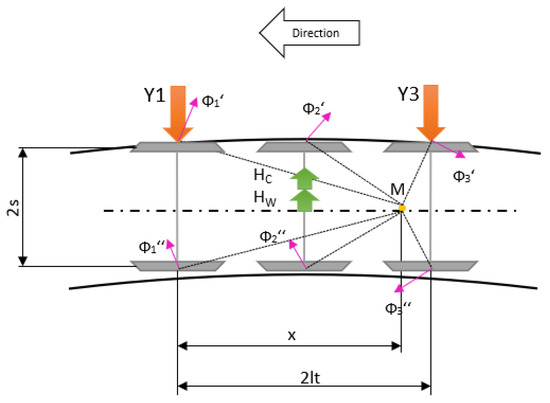
Case 4: Maximum Lateral Displacement (Outer Rail Contact). In this state, the bogie reaches its maximum lateral displacement, where the wheel flanges of both the leading (first) and trailing (third) wheelsets achieve simultaneous contact with the outer rail. Unlike the “skewing” positions, the bogie frame does not assume a diagonal orientation across the track gauge but instead aligns itself parallel or as a chord relative to the outer rail head. This configuration typically occurs in large-radius curves where centrifugal forces press the entire frame outward. The leading and trailing guiding forces (Y1 and Y3) are generated by contact with the outer rail, as shown in Figure 4, while the intermediate (second) wheelset remains floating within the track clearance, its position governed by the geometric versine of the curve relative to the rigid wheelbase.
Figure 4.
Maximum Lateral Displacement.
2.2.2. A Methodological Approach to the Theoretical Estimation of Axle Guiding Forces (Yi) in Three-Axle Bogie Vehicles
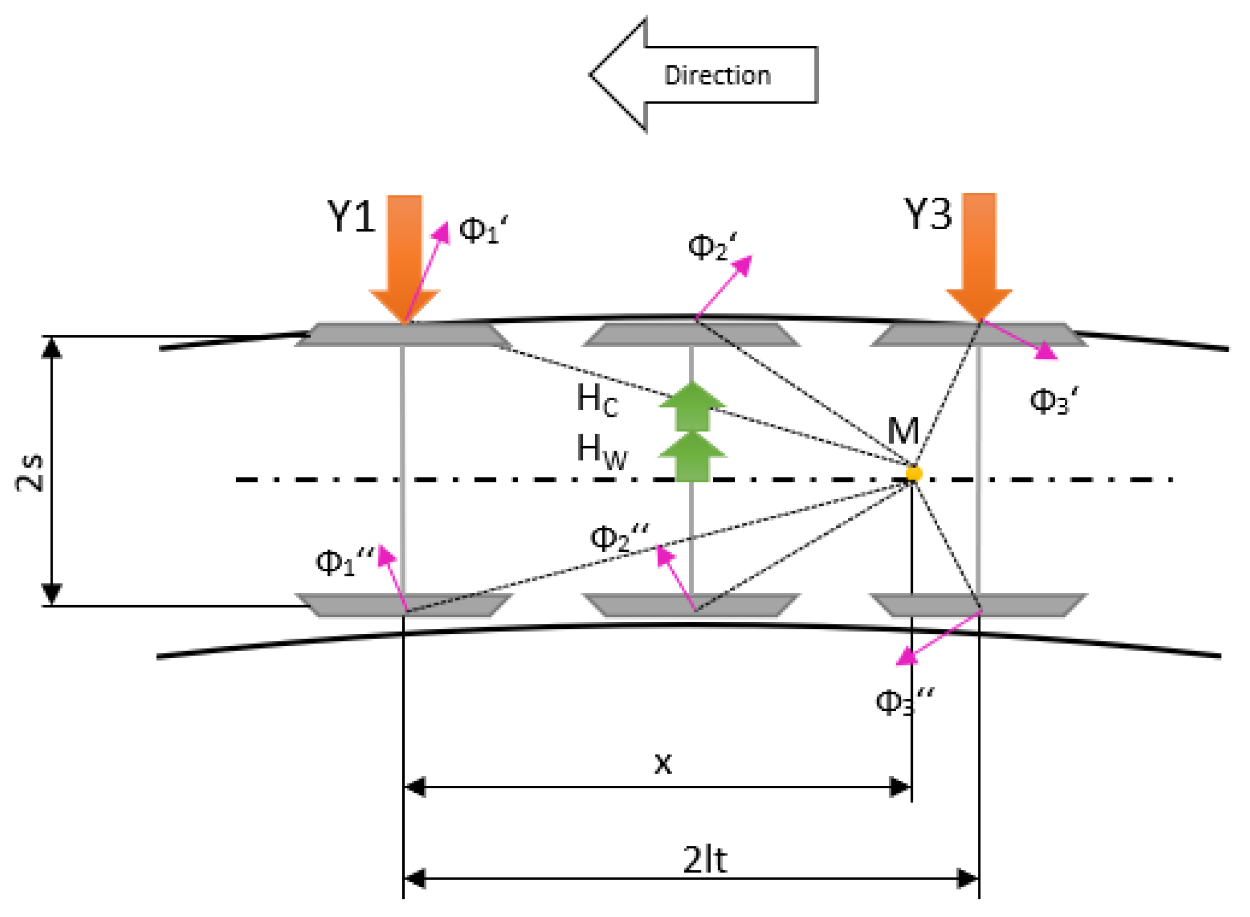
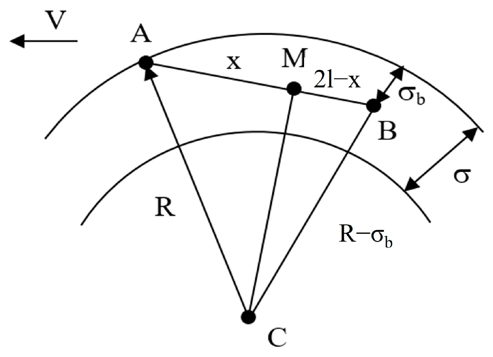
A theoretical framework for calculating the total rail reaction on bogie wheels is presented in [2,10]. Briefly, the method assumes that a wagon negotiating a curve undergoes simultaneous translational and rotational motion. This rotation pivots around a center M (Figure 5) [2,10], characterized by a pole distance, x, which is determined using Equation (1) [2,10].
where 2l is the bogie wheelbase (corresponding to standard European notation 2a+), R is the curve radius, and σB is the current coordinate.
Figure 5.
Movement of bogie in curved section of the track [2,10].
Equation (2) [2,10] defines the reduced gauge:
where Δ is the total clearance between the wheel flange and the rail (0.01 m), and δ represents the gauge widening in curved sections, determined as a function of the curve radius according to Table 1 [2,10,11].
Table 1.
Additional expansion of the rail track in a curved section depends on the radius of the calculation curve [2,10,11].
Depending on the running speed and the curve radius, the bogie may assume one of the following positions, where [2,10]:
- σB = σ = Δ + δ—for maximal crossing;
- 0 ≤ σB ≤ δ—for free settling;
- σB = 0—maximum displacement.
As the three-axle bogie travels through a curve, the following forces are applied:
- (1)
- Centrifugal force is defined using Equation (3) [2,10]:
- (2)
- The wind force is determined via Equation (5) [2,10]:
- (3)
- The frictional forces Φ resulting from rotation around the pole M are calculated using Equation (6) [2,10]:
- (4)
- The total reaction Yi from rails on the wheelset i for the different positions of the bogie in the curve are obtained from the equilibrium conditions ∑Y = 0 and ∑MM = 0. The methodology outlined below details the procedure for determining the Horizontal Dynamic Passport for three-axle bogie:
- Step 1. Determination of the speed v1 and the corresponding lateral force Y1 for the case where the first and the third wheelset make contact with the rails. This state examines the precise moment when the leading wheelset is in contact with the outer rail, while the third wheelset is on the verge of making contact with the inner rail. The speed v1 denotes the upper limit of the “Maximum Crossing” regime. For this computational state, it is assumed that the lateral guiding forces on the intermediate and trailing wheelsets are zero (Y2 = 0 and Y3 = 0), and the pole distance reaches its maximum theoretical value (x = xmax). The analysis is based on the computational scheme, as illustrated in Figure 2. Equation (8) for this configuration are expressed as follows:where Φyi represents the lateral component of the force Φ along the y-axis, and ri denotes the distance from the pole of rotation M to the corresponding wheel–rail contact point of the i-th wheelset. The analysis thus far has considered the scenario in which the leading and third wheelsets make contact with the rails. For this computational scheme, the pole distance x is determined according to Equation (1). The solution of the equations yields the values of v1 and Y1.
- Step 2. Determination of the speed v1 and the corresponding lateral force Y1. The speed v1 denotes the upper limit of the “Maximum Crossing” regime for the “Maximum Crossing” case, where the first and the second wheelset make contact with the rails. This state examines the precise moment when the leading wheelset is in contact with the outer rail, while the second wheelset is on the verge of making contact with the inner rail. For this computational state, it is assumed that the lateral guiding forces on the intermediate and trailing wheelsets are zero (Y2 = 0 and Y3 = 0), and the pole distance reaches its maximum theoretical value (x = xmax). The analysis is based on Figure 1. The equations for this configuration are the same as (8). For this computational scheme, the pole distance x is determined according to Equation (9).
- Step 3. Defining the speed v2 (the speed at the end of case “Free Settling”). This state examines the precise moment when the leading wheelset is in contact with the outer rail, while the third wheelset is on the verge of making contact with the outer rail. The boundary conditions and governing equations remain identical to those detailed in Steps 1 and 2. The sole distinction lies in the pole distance x, which is assumed to reach its minimum value (x = xmin). The solution of the equations yields the values of v2 and Y1.
- Step 4. Determination of the lateral forces Y1 and Y2 for the “Maximum crossing” interval with flange contact at the leading and intermediate wheelsets. When the bogie is in the ‘Maximum Crossing’ state, it operates at a speed within the interval from 0 to v1 (evaluated at discrete speed values), while the pole distance is maintained at x = xmax. Consequently, based on the computational scheme illustrated in Figure 1, the system of equations is formulated as follows (10):For this computational scheme, the pole distance x is determined according to Equation (9). The solution of the equations yields the values of Y1 and Y2.
- Step 5. Determination of the lateral forces Y1 and Y3 for the “Maximum crossing” interval with flange contact at the leading and third wheelsets. The speed is in the interval from 0 to v1 (evaluated at discrete speed values), while the pole distance is maintained at x = xmax (using Equation (1)). Consequently, based on the computational scheme illustrated in Figure 2, the system of equations is formulated as follows (11):The solution of the equations yields the values of Y1 and Y3.
- Step 6. Determination of the lateral force Y1 and the speed v for the interval “Free Settling”. Within this range, contact occurs between the flange of the outer wheel of the leading wheelset and the rail. Consequently, the analytical model depicted in Figure 3 is applied. In this interval, the velocity is calculated in the range from v1 to v2, whereas the pole distance varies from xmax to xmin. Discrete values of the pole distance are prescribed, and the governing system of Equation (12) is solved:
- Step 7. Determination of the lateral forces Y1 and Y3 for the interval “Maximum Displacement”. During this interval, the flanges of the outer wheels on both the leading and trailing wheelsets make contact with the outer rail of the curve. The governing Equation (13) are derived based on the computational scheme presented in Figure 4, and they are expressed as follows:The velocity in this regime spans from v2 to the maximum design speed vk, assigned as discrete values across the interval. The system of equilibrium equations is solved with respect to Y1 and Y3.
2.3. Horizontal Dynamic Passport (HDP) Generation
Based on the described methodology, a series of calculations were performed for different wheelbase configurations (2l = 3.0, 3.4, 3.6, 4.0 m). The results are presented through a family of curves showing the dependence of lateral forces on movement speed for various curve radii (R). The primary safety criterion evaluated is the derailment coefficient according to EN 14363 [4], defined as (Y/Q)lim < 1.2.
All calculations and the graphical presentation of the results were performed using Microsoft Excel, Version 2108 (Build 14334.20756), included in Microsoft Office LTSC Standard 2021 (Microsoft Corporation, Redmond, WA, USA).
3. Results
The results of the comparative analysis based on the Horizontal Dynamic Passport (HDP) methodology are presented as diagrams of the lateral forces as a function of speed, Yi = f(v). The study focuses on the distribution of lateral guiding forces (Y1, Y2, Y3) across the three axles for four different wheelbase configurations (2l = 3.0, 3.4, 3.6, 4.0 m) under varying curve radii. Depending on the curve radii, the reaction forces are limited by the maximum permissible curve negotiation speed, in accordance with the EN 13803 standard [12].
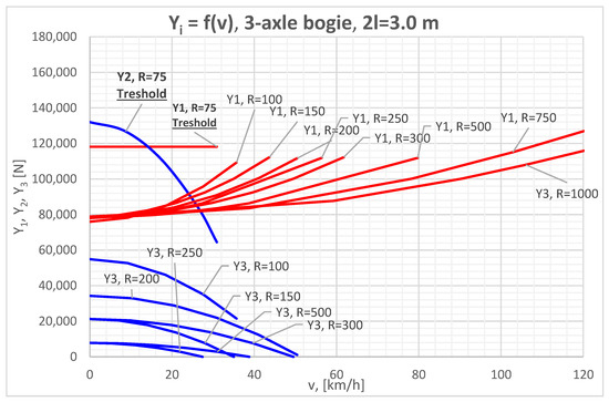
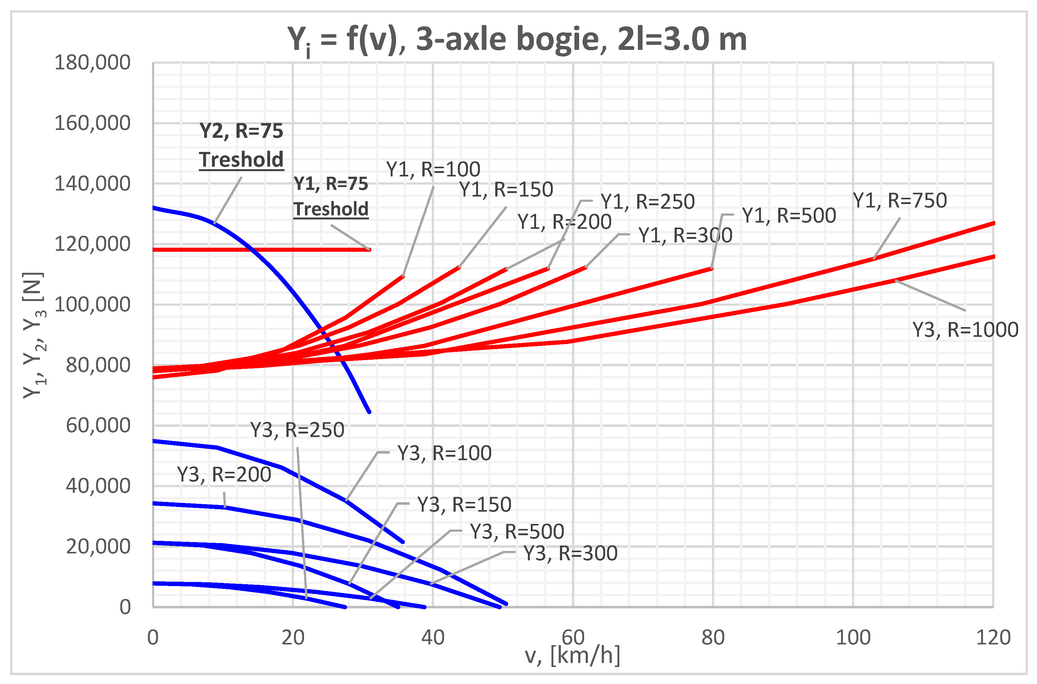
Figure 6 illustrates the results for a three-axle bogie with a rigid wheelbase of 2l = 3 m. The investigation covers a range of curve radii from 75 m to 1000 m, with the speed varying from 0 to the maximum design speed of vk = 120 km/h.
Figure 6.
Lateral guiding forces Yi as a function of travel speed v for various curve radii (R = 75–1000 m) and a fixed bogie wheelbase 2l = 3 m.
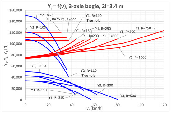
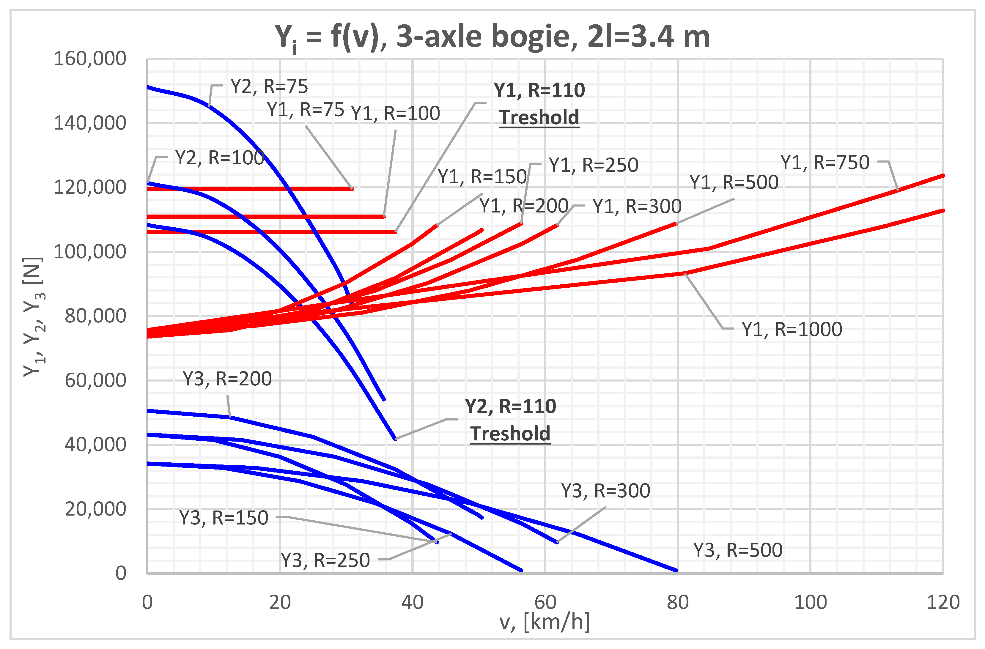
The computational results for a three-axle bogie with an extended rigid wheelbase of 2l = 3.4 m are presented in Figure 7.
Figure 7.
Lateral guiding forces Yi as a function of travel speed v for various curve radii (R = 75–1000 m) and a fixed bogie wheelbase 2l = 3.4 m.
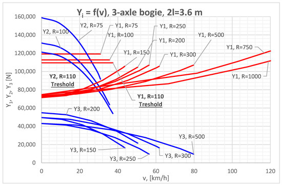
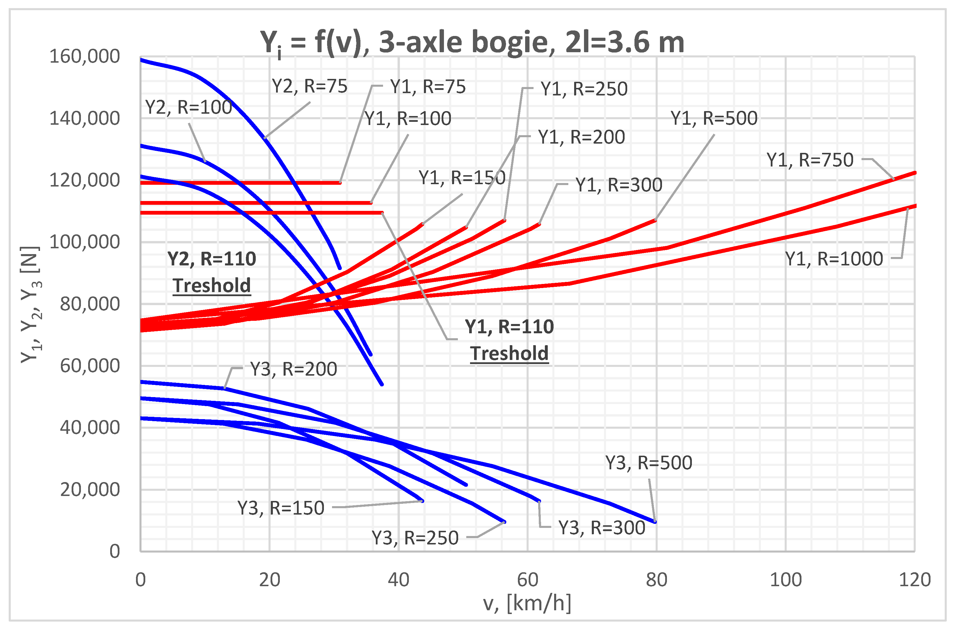
Figure 8 presents the computational analysis of a three-axle bogie configured with an increased rigid wheelbase of 2l = 3.6 m.
Figure 8.
Lateral guiding forces Yi as a function of travel speed v for various curve radii (R = 75–1000 m) and a fixed bogie wheelbase 2l = 3.6 m.
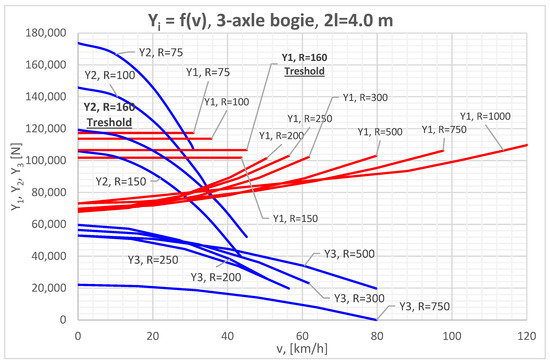
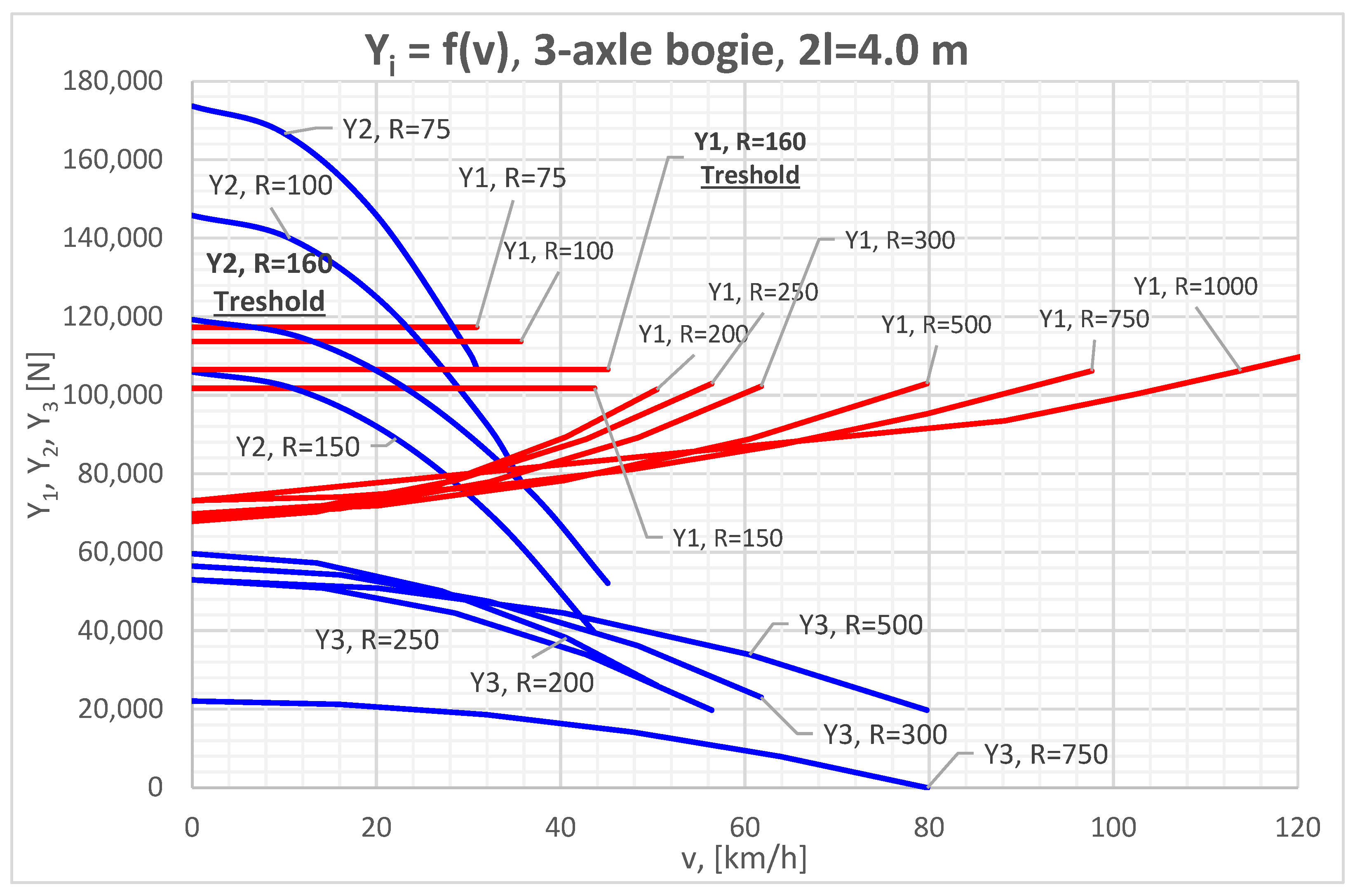
The dynamic performance results for a three-axle bogie with a 4 m rigid wheelbase are illustrated in Figure 9.
Figure 9.
Lateral guiding forces Yi as a function of travel speed v for various curve radii (R = 75–1000 m) and a fixed bogie wheelbase 2l = 4 m.
4. Discussion
The results obtained through the Horizontal Dynamic Passport (HDP) methodology highlight a complex, non-linear relationship between the three-axle bogie’s rigid wheelbase (2l) and the resulting lateral force distribution. The following points analyze the core physical behaviors observed in the diagrams.
4.1. Transition Between Kinematic Guiding Modes
One of the findings of this study is the identification of a geometric threshold where the kinematic behavior of the three-axle bogie shifts between distinct guiding modes.
- Leading-Trailing Contact: For wheelbases up to 3.6 m, the bogie negotiates curves by maintaining flange contact at the leading (1st) and trailing (3rd) wheelsets against the rails from R > 110 m. In this state, the intermediate (middle) wheelset “floats” within the available track clearance (σ).
- Leading-Intermediate Contact: When the wheelbase reaches 4.0 m, the geometric versine of small-radius curves (R < 150 m) exceeds the available lateral play.
4.2. Influence of Wheelbase Length on Lateral Force
The rigid wheelbase (2l) acts as a primary determinant of the bogie’s dynamic geometric incompatibility during curve negotiation. As the wheelbase increases from 3.0 m to 4.0 m, the lateral forces Y2 and Y3 rise significantly due to the increased stiffness of the frame relative to the track curvature. In small-radius curves (R < 150 m), this lack of geometric compatibility forces a kinematic shift: while Y1 may remain constant under a “geometric lock,” the intermediate axle is forced into hard flange contact to compensate for the lengthening frame. Our results show that while wheelbases up to 3.6 m stay within safe limits, the 4.0 m configuration causes a spike in Y2, often exceeding the 1.2 derailment threshold and narrowing the vehicle’s safety envelope.
4.3. Assessment of Safety Compatibility and Operational Limits
The “Horizontal Dynamic Passport” (HDP) serves as an objective tool for assessing the safety compatibility of various three-axle bogie designs with existing railway infrastructure. According to Nadal’s criterion, the safety threshold is maintained as long as the derailment coefficient remains below the (Y/Q) < 1.2 limit. For standard wheelbases of 3.0 m to 3.6 m, the lateral interaction forces (Yi) generally fall within this safe “passport” envelope across most operational speeds and radii. However, the 4.0 m configuration exhibits a clear breach of safety compatibility in tight curves (R < 150 m), where the geometric penalty forces the Y/Q ratio to exceed the 1.2 threshold. In these specific cases, the bogie reaches a “geometric lock” where the risk of flange climbing or lateral track shift is governed by the rigid wheelbase rather than centrifugal forces. Consequently, ensuring safety compatibility for extended wheelbases requires either mandatory speed restrictions in industrial sidings or modifications to track clearance parameters as defined in EN 13803 [12].
5. Conclusions
This paper presented a comparative analysis of the lateral dynamics of three-axle bogies with varying rigid wheelbases (2l = 3.0, 3.4, 3.6, 4.0 m) using the Horizontal Dynamic Passport methodology. Based on the results, the following conclusions are drawn:
- Critical Geometric Threshold: There exists a critical wheelbase length between 3.6 m and 4.0 m for curves with a radius of R = 150 m. Crossing this threshold alters the guiding mechanism, transferring the lateral load from the trailing axle (Y3) to the middle axle (Y2).
- Safety Compromise in Long Wheelbases: The configuration with 2l = 4.0 m exhibits significantly higher lateral forces on the inner rail (Y2) in tight curves. This increases the risk of derailment and infrastructure damage compared to shorter wheelbases (3.0–3.4 m), which distribute the guiding forces more evenly between the first and third axles.
- Optimal Design Range: For freight wagons intended for operation on networks with diverse track geometry (including tight industrial curves), a rigid wheelbase in the range of 3.4 m to 3.6 m offers the optimal balance between running stability on straight tracks and curving performance.
- Utility of HDP: The Horizontal Dynamic Passport successfully identifies the safe operational envelope for various geometric configurations, assisting manufacturers in selecting the optimal wheelbase design. This facilitates the development of freight wagons with enhanced payload capacities, thereby delivering significant economic and environmental benefits through the application of three-axle bogies.
The determined lateral interaction forces for the three-axle bogie provide a significant basis for further structural evaluations. These results can be integrated into a specialized methodology for calculating the material fatigue of the bogie frame’s welded joints [13], ensuring both operational safety and long-term structural reliability.
Future Work: Further research should focus on verifying these quasi-static results with multi-body dynamic simulations (MBS) incorporating track irregularities and investigating the effect of non-linear friction coefficients on the transition between guiding modes.
Funding
The use of technical equipment is supported by the Operational Programme “Research, Innovation and Digitalization for Smart Transformation 2021–2027” under Project No. BG16RFPR002-1.014-0006-C01 “National center of excellence for mechatronics and clean technologies”.
Institutional Review Board Statement
Not applicable.
Informed Consent Statement
Not applicable.
Data Availability Statement
The data supporting the results of this study from the computational models are not publicly available due to commercial confidentiality and proprietary rights. Data may be made available upon reasonable request and with permission from the respective institutions.
Acknowledgments
Operational Programme “Research, Innovation and Digitalization for Smart Transformation 2021–2027” under Project No. BG16RFPR002-1.014-0006-C01 “National center of excellence for mechatronics and clean technologies”. During the preparation of this manuscript, the author used Google Gemini 3.1 Pro, accessed through a Google AI Pro subscription (Google LLC, Mountain View, CA, USA) for the purposes of translating text into academic English, refining the scientific language, and structuring the manuscript sections. The author has reviewed and edited the output and takes full responsibility for the content of this publication.
Conflicts of Interest
The author declares no conflicts of interest.
References
- Bosso, N.; Magelli, M.; Zampieri, N. Dynamical Effects of the Increase of the Axle Load on European Freight Railway Vehicles. Appl. Sci. 2023, 13, 1318. [Google Scholar] [CrossRef] [Scilit]
- Stoilov, V.; Slavchev, S.; Maznichki, V.; Purgic, S. Method for Theoretical Assessment of Safety against Derailment of New Freight Wagons. Appl. Sci. 2023, 13, 12698. [Google Scholar] [CrossRef] [Scilit]
- Nadal, M. Locomotives à Vapeur (Steam Locomotives); Collection Encyclopédie Scientifique, Bibliothèque de Mécanique Appliquée et Génie; O. Doin: Paris, France, 1908. [Google Scholar]
- EN 14363:2019; Railway Applications—Testing and Simulation for the Acceptance of Running Characteristics of Railway Vehicles—Running Behaviour and Stationary Tests. European Committee for Standardization: Brussels, Belgium, 2019.
- EN 16235:2013; Railway Applications—Testing for the Acceptance of Running Characteristics of Railway Vehicles—Freight Wagons—Conditions for Dispensation of Freight Wagons with Defined Characteristics from On-Track Tests According to EN 14363. European Committee for Standardization (CEN): Brussels, Belgium, 2013.
- Michálek, T.; Haupt, L.; Zelenka, J.; Kohout, M.; Liberová, S. Lateral force effects of three-axle locomotive bogie on track. Appl. Comput. Mech. 2018, 12, 33–44. [Google Scholar] [CrossRef] [Scilit][Green Version]
- Putyato, A.; Brilkov, G. Evaluation of resistance against the derailment and strength of wheel shunting locomotive of ChME3 series when moving in curve of small radius. Actual Issues Mach. Sci. 2019, 8, 65–70. [Google Scholar]
- Fomina, Y.; Moravčík, M. An experimental analysis of the forces impact of a new structural design of a three-axle railway bogie to a track. Transp. Res. Procedia 2021, 55, 821–828. [Google Scholar] [CrossRef] [Scilit]
- Gholamizadeh, K.; Pamucar, D.; Moslem, S.; Basiri, P.; Esztergár-Kiss, D.; Mohammadfam, I. Decoding rail derailments: Unraveling the weighted factors influencing safety and sustainability using the best-worst method. Results Eng. 2024, 23, 102539. [Google Scholar] [CrossRef] [Scilit]
- Stoilov, V.; Slavchev, S. Wagons, 1st ed.; Technical University Sofia: Sofia, Bulgaria, 2014; pp. 150–156. ISBN 978-619-167-135-9. (In Bulgarian) [Google Scholar]
- Zeng, Y.; Wilson, N.; Lundberg, W.; Walker, R.; Shu, X.; Jones, M. Geometric Criterion for Flange Climb Derailment and IWS-Based Implementation. In Advances in Dynamics of Vehicles on Roads and Tracks II. IAVSD 2021; Orlova, A., Cole, D., Eds.; Lecture Notes in Mechanical Engineering; Springer: Cham, Switzerland, 2022. [Google Scholar] [CrossRef] [Scilit]
- EN 13803:2017; Railway Applications—Track—Track Alignment Design Parameters—Track Gauges 1 435 mm and Wider. European Committee for Standardization: Brussels, Belgium, 2017.
- Slavchev, S.; Maznichki, V.; Stoilov, V.; Enev, S.; Purgich, S. Methodology for assessment of material fatigue in the area of welded joints of railway bogies by calculation. IOP Conf. Ser. Mater. Sci. Eng. 2019, 618, 012046. [Google Scholar] [CrossRef] [Scilit]


Disclaimer/Publisher’s Note: The statements, opinions and data contained in all publications are solely those of the individual author(s) and contributor(s) and not of MDPI and/or the editor(s). MDPI and/or the editor(s) disclaim responsibility for any injury to people or property resulting from any ideas, methods, instructions or products referred to in the content. |
© 2026 by the author. Licensee MDPI, Basel, Switzerland. This article is an open access article distributed under the terms and conditions of the Creative Commons Attribution (CC BY) license.