


Abstract
Robotic end-effectors play an important role in automated pick-and-place operations, particularly where lightweight components with different geometries must be handled reliably. This study presents the design, fabrication, integration, and comparative experimental evaluation of three lightweight robotic gripper architectures for a Dobot CR5 collaborative robot using fused deposition modeling (FDM). The investigated architectures comprise a parallel dual-finger gripper, a lightweight micro-servo linkage gripper, and a concentric three-finger gripper. An embedded sensor-assisted system incorporating ultrasonic proximity sensing and force-sensitive resistor (FSR) feedback was implemented using threshold-based control logic. The three architectures were evaluated under identical operating conditions using spherical polypropylene and cylindrical polyethylene workpieces over 1000 consecutive pick-and-place cycles per configuration. Grasp success, dropped-object events, structural integrity, cycle performance, positioning variation, maximum dynamic load, and electrical energy consumption were considered as performance metrics. Within the investigated test conditions, the concentric three-finger architecture achieved the highest grasp success rate of 98.4%, corresponding to 984 successful cycles and 16 dropped-object events, with no observable structural failure. The results indicate that the symmetric three-contact architecture provided improved grasp stability and structural behavior relative to the two alternative configurations for the tested polymer workpieces. The study demonstrates the value of controlled architecture-to-architecture evaluation in the development of additively manufactured robotic end-effectors while identifying broader object validation, long-term durability testing, calibrated force sensing, and continuous force regulation as areas for future investigation.
1. Introduction
Collaborative robots have become increasingly important in modern manufacturing because of their ability to perform repetitive operations while working in environments shared with human operators [1,2]. Typical applications include assembly, packaging, inspection, sorting, and material handling. In these applications, overall manipulation performance depends not only on the robot manipulator but also on the end-effector, which establishes the mechanical interaction between the robotic system and the workpiece [3].
Robotic grippers can employ rigid, compliant, soft, vacuum-based, magnetic, or hybrid grasping strategies depending on the workpiece and application. Conventional parallel-jaw grippers remain widely used because of their mechanical simplicity, positioning accuracy, and compatibility with industrial automation. Their grasp stability, however, can be sensitive to object geometry, friction, contact position, and acceleration during robot motion. Vacuum end-effectors can provide rapid handling but require suitable surface conditions, while magnetic grippers are restricted to magnetically responsive materials. These limitations have motivated the development of adaptive, compliant, and multi-contact grasping mechanisms [4].
Soft and compliant robotic grippers provide an alternative strategy by accommodating object geometry through structural deformation, deformable materials, or compliant mechanisms. Recent reviews have demonstrated substantial progress in pneumatic, tendon-driven, elastomeric, bio-inspired, and smart-material grippers for manufacturing, agricultural, biomedical, and general manipulation applications. Their mechanical compliance can improve conformity to irregular or delicate objects, although challenges remain in positioning accuracy, durability, fabrication, sensing integration, and control [5,6].
Additive manufacturing has become an important enabling technology for both rigid and compliant end-effector development. Material-extrusion processes such as FDM and fused filament fabrication allow customized geometries to be produced directly from digital CAD models and permit rapid modification of finger geometry, contact interfaces, and mounting features. Rigid thermoplastics such as polylactic acid (PLA) can also be combined with more compliant materials such as thermoplastic polyurethane (TPU) to tailor structural and contact behavior. Recent research has extended these capabilities through multimaterial printing, variable-stiffness structures, compliant restoration mechanisms, and sensor-integrated gripping systems [7,8].
Recent additively manufactured grippers have also incorporated force, tactile, proximity, and other sensing modalities to improve state awareness during grasping. Consequently, additive manufacturing, servo actuation, multi-finger grasping, and embedded sensing are established elements of robotic-gripper research and should not individually be regarded as the novelty of the present work [9].
Despite these advances, direct experimental comparison of mechanically distinct additively manufactured gripper architectures under a common robotic platform and identical test protocol remains useful. Many reported studies focus on the optimization of a single architecture, while differences in robot platforms, object geometry, trajectory, actuator specification, sensing method, and performance criteria complicate direct comparison across independent studies.
Accordingly, the present study investigates three mechanically distinct lightweight gripper architectures: a parallel dual-finger mechanism, a micro-servo linkage mechanism, and a concentric three-finger mechanism. All three were fabricated using FDM and evaluated using the same Dobot CR5 collaborative robot under a common experimental protocol [2,10]. The objective is not to claim novelty from FDM fabrication or sensor integration alone, but to determine how differences in mechanical architecture influence repetitive polymer pick-and-place performance under controlled conditions.
The main contributions of this work are:
- Design and fabrication of three mechanically distinct lightweight robotic gripper architectures using FDM for comparative evaluation on a common collaborative robotic platform.
- Integration of ultrasonic proximity sensing and FSR tactile feedback within an embedded sensor-feedback-based threshold control architecture.
- Controlled experimental comparison of the three gripper designs using the same robot platform, operating parameters, and representative polymer workpieces over 1000 consecutive pick-and-place cycles per configuration.
- Quantitative comparison of grasp success, dropped-object events, structural behavior, cycle performance, positioning variation, maximum dynamic load, and electrical energy consumption were supported by the experimental records.
The remainder of the paper is organized as follows. Section 2 describes the gripper architectures, additive manufacturing procedure, structural analysis, embedded sensing architecture, firmware, electrical interface, and experimental methodology. Section 3 defines the experimental procedure and evaluation metrics. Section 4 presents the experimental results. Section 5 discusses the findings in relation to mechanical architecture, sensing strategy, the recent literature, manufacturing implications, and study limitations. Section 6 summarizes the principal conclusions.
2. Materials and Methods
2.1. Gripper Architectures and Design Rationale
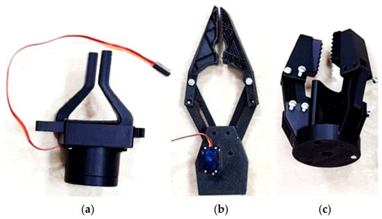
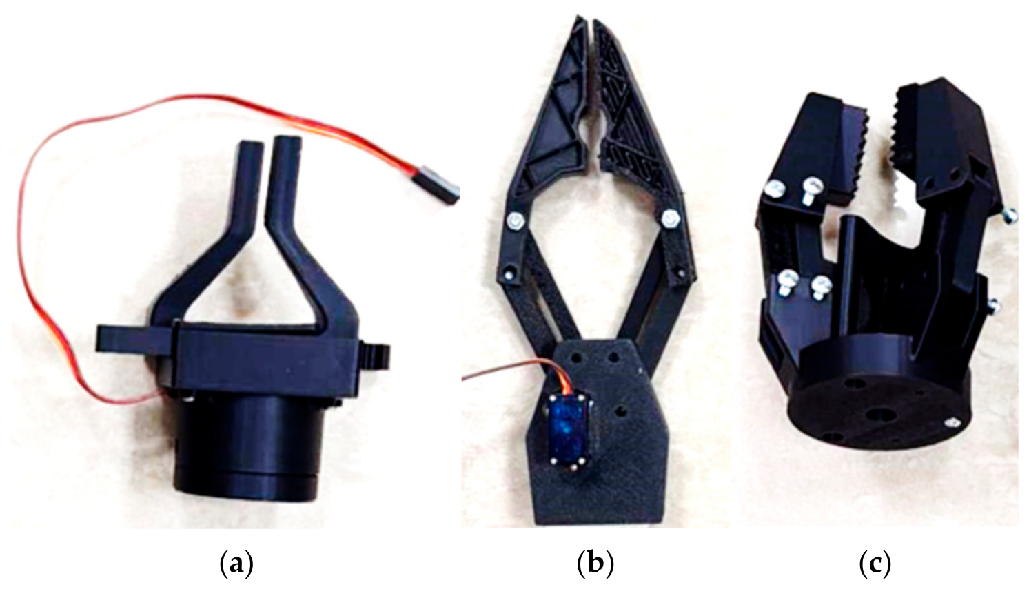
Three mechanical architectures in Figure 1 were developed to compare different contact arrangements, load paths, and structural characteristics while remaining compatible with the payload and mounting requirements of the Dobot CR5 collaborative robot (Shenzhen Dobot Corp Ltd., Shenzhen, China) [11,12,13].
Figure 1.
The three FDM-fabricated gripper architectures investigated in this study: (a) parallel dual-finger gripper (Design-1); (b) micro-servo linkage gripper (Design-2); and (c) concentric three-finger gripper (Design-3).
2.1.1. Parallel Dual-Finger Architecture (Design-1)
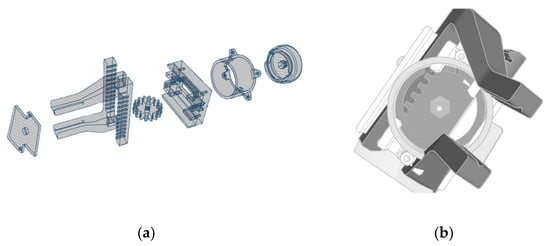
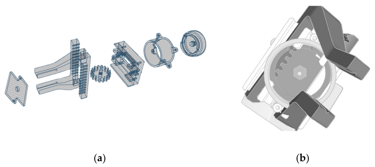
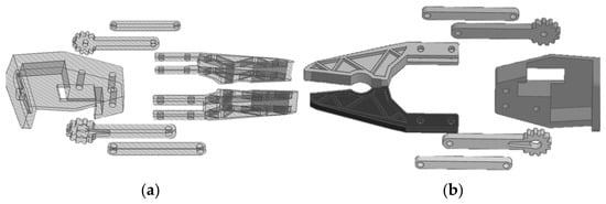
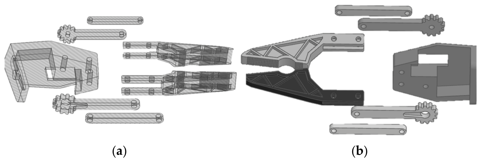
The first configuration in Figure 2 employs two opposing fingers driven through a rack-and-pinion transmission. A central pinion converts actuator rotation into symmetric linear motion of the two sliding racks.
Figure 2.
Structural layout of the parallel dual-finger gripper (Design-1): (a) FDM-fabricated components; (b) CAD assembly.
The principal mechanical components include:
- Two opposing interlocking sliding racks with internal guides;
- A central drive pinion coupled to the actuator;
- A split structural housing containing the rack paths;
- A mounting flange compatible with the Dobot CR5 end-effector interface.
The architecture provides comparatively rigid linear guidance and mechanically simple opposing motion. However, object constraint is generated primarily through two contact regions, making grasp stability dependent on friction, object geometry, and contact position.
2.1.2. Micro-Servo Linkage Architecture (Design-2)
The second configuration in Figure 3 was developed to minimize end-effector mass through a lightweight mechanical-linkage arrangement actuated by a sub-miniature 9 g servo motor. The mechanism uses slender linkage members to transmit actuator motion to the fingers.
Figure 3.
Structural layout of the micro-servo linkage gripper (Design-2): (a) FDM-fabricated components; (b) CAD assembly.
The reduced structural mass provides rapid actuation and preserves more of the robot’s available payload capacity. However, the slender links and pin joints have lower bending stiffness than the more compact transmission arrangements and may undergo elastic deformation under dynamic loading.
2.1.3. Concentric Three-Finger Architecture (Design-3)
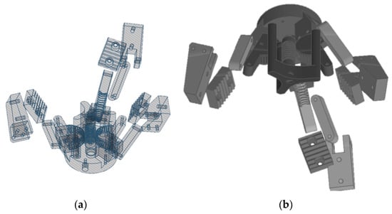
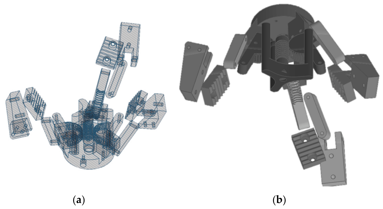
The third configuration in Figure 4 employs three circumferentially arranged fingers driven by a central gear and three synchronized planetary spur gears positioned approximately 120° apart. The arrangement converts rotary actuation into inward radial finger motion.
Figure 4.
Structural layout of the concentric three-finger gripper (Design-3): (a) FDM-fabricated components; (b) CAD assembly.
Unlike the two-contact architecture, the concentric design provides three distributed contact locations around the target object. This geometry is intended to improve mechanical constraint and resistance to translational and rotational displacement by distributing contact around the object rather than relying exclusively on two opposing frictional contacts.
The present experiments do not establish geometry-independent grasping; instead, the architecture is evaluated specifically for the workpieces and operating conditions described in Section 2.7.
2.2. Additive Manufacturing and Prototype Fabrication
The structural components of the three gripper architectures were fabricated [14,15,16], using fused deposition modeling. PLA was used for the principal structural components, while TPU was applied at selected contact interfaces to increase compliance and friction between the gripper and the polymer workpieces.
A common material-extrusion fabrication approach was maintained across all three architectures to reduce manufacturing-process variability during the comparative evaluation. The prototypes were produced using fabrication parameters such as a Prusa MK4 printer with a 0.4 mm nozzle. Following fabrication, the components were visually inspected, assembled with the corresponding actuators and mechanical hardware, and integrated with the standardized Dobot CR5 mounting interface.
2.3. Structural Analysis
Numerical structural analysis was performed to identify potential stress concentrations and compare the relative structural response of the three architectures under a common nominal loading condition. Each architecture was analyzed under a nominal clamping load of 25 N.
Under the modeling assumptions used in the original analysis, the parallel dual-finger configuration exhibited a maximum reported stress of 18.4 MPa near the root of the first rack tooth. The micro-servo linkage architecture exhibited a maximum reported stress of 24.1 MPa around the principal pin-joint and slender-link regions. The concentric three-finger configuration exhibited a lower reported maximum stress of 6.2 MPa near the gear-contact regions.
These numerical results are used primarily to compare stress localization and identify potentially vulnerable structural regions. Their absolute magnitude depends on the material model, print orientation, contact assumptions, constraints, and applied loading.
2.4. Control Topology and Embedded System Framework
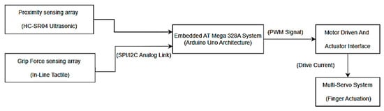
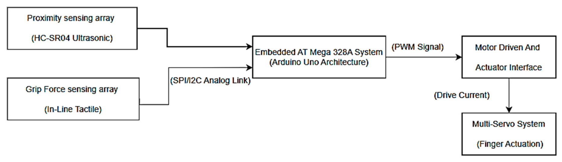
The end-effector incorporated an ATmega328P-based embedded controller (Microchip Technology Inc., Chandler, AZ, USA) [17,18], an HC-SR04 ultrasonic transceiver (Shenzhen Shenmingyang Electronics Co., Ltd., Shenzhen, China), an FSR contact sensor (Interlink Electronics, Inc., Camarillo, CA, USA), servo actuators, and a diagnostic LED as shown in Figure 5. The HC-SR04 was used to estimate object proximity from ultrasonic echo duration. The TRIG and ECHO lines were connected to digital pins 3 and 2, respectively. The FSR provided a contact-dependent analog electrical response that was sampled through the microcontroller’s analog-to-digital converter through pin A0.
Figure 5.
Functional block diagram of the sensor-assisted end-effector architecture.
2.5. Firmware and Sensor-Feedback Logic
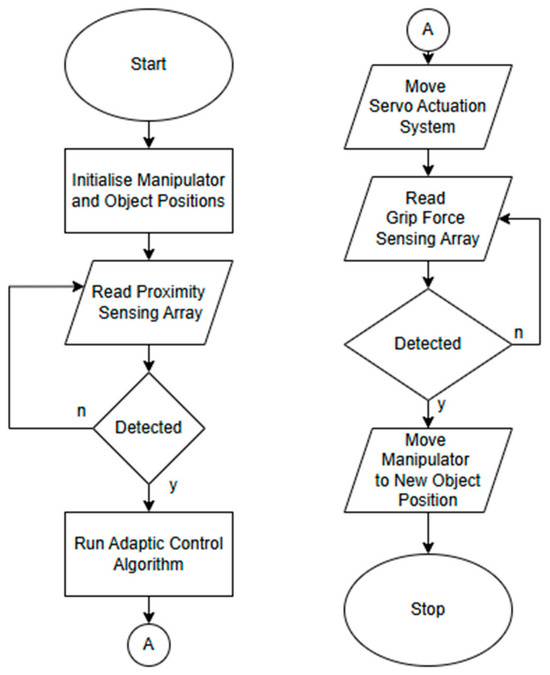
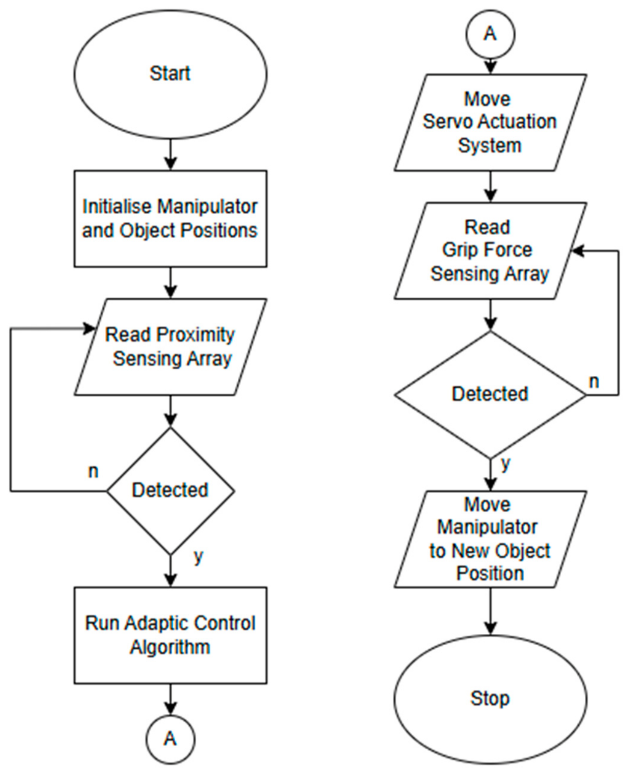
The embedded firmware implements sequential sensor acquisition and threshold-based actuation as shown in Figure 6. The principal firmware constants are:
Figure 6.
Firmware logic for ultrasonic proximity sensing, FSR threshold detection, and servo actuation.
- Ultrasonic stabilization threshold: 50 cm;
- Critical distance threshold: 10 cm;
- FSR threshold: 450 ADC counts.
The ultrasonic sensor is triggered for 10 microseconds and the echo duration is measured using the firmware timing routine. Distance is estimated using d = 0.01715 t, where d is distance in centimeters and t is the round-trip echo duration in microseconds. If no valid echo is received within the implemented 30 ms timeout, the firmware assigns an out-of-range value of 999 cm.
The FSR signal is read from analog input A0 in the firmware also shown in Appendix A and its algorithm in Table 1. The 0-1023 ADC range is also mapped to a nominal 0–180° command for jointActuatorA with jointActuatorB as an option for alternative integrations. The firmware subsequently applies threshold logic:
Table 1.
Algorithm steps employed in firmware development.
- If the measured distance is below 10 cm or the FSR value exceeds the threshold, the stabilizer is commanded to the protective/contact state and the diagnostic LED is activated;
- If the measured distance is between 10 and 50 cm, the stabilizer is commanded to the alternate predefined position;
- If the object is outside the 50 cm boundary, the stabilizer remains in its default state.
The implemented system therefore uses measured sensor inputs to select discrete actuator states through conditional branching. It does not implement continuous closed-loop force regulation because no desired force setpoint is defined and no force-error signal is continuously minimized using proportional, integral, derivative, or equivalent control action. The control approach is therefore described throughout this manuscript as sensor-feedback-based threshold control.
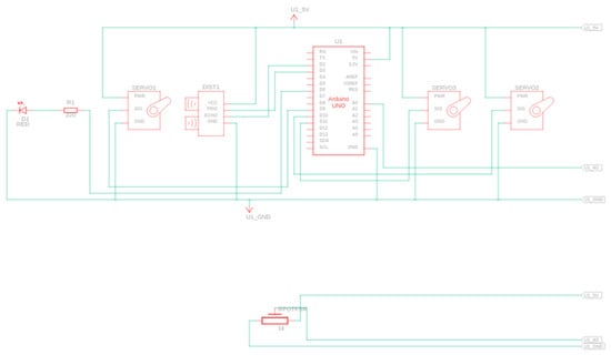
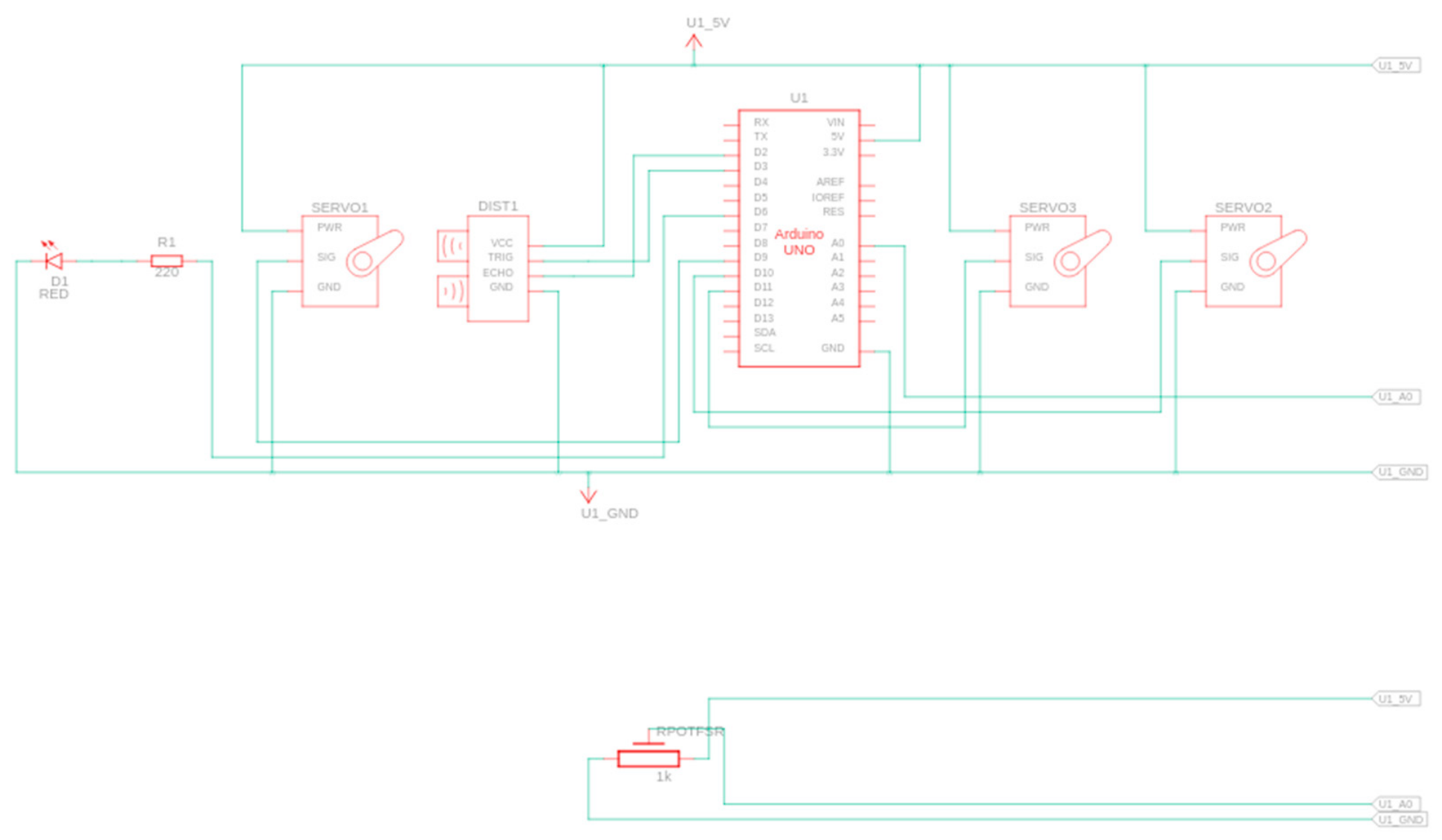
2.6. Electrical Interface and Circuit Schematic
The electrical interface shown in Figure 7 connected the ATmega328P-based controller to the ultrasonic sensor, servo actuators, FSR input, and diagnostic LED. The HC-SR04 TRIG and ECHO terminals were connected to digital pins 3 and 2, respectively, and echo duration was measured using the firmware timing routine. The actuator signals were generated using the Arduino Servo library, with the servo pulse range configured between 500 and 2500 µs. A diagnostic LED was connected through a 220 Ω current-limiting resistor to indicate the active contact/protective threshold state.
Figure 7.
Electrical connection schematic of the sensor-assisted gripper system.
2.7. Experimental Setup
The three fabricated grippers were experimentally evaluated using a Dobot CR5 collaborative robot. The test objects consisted of:
- Spherical polypropylene specimens, diameter 8.5 mm;
- Cylindrical polyethylene specimens, length 14.2 mm and diameter 6.0 mm.
These two object configurations were selected to provide controlled geometric variation within the investigated polymer-handling task. The purpose of the experimental protocol was to compare the three gripper architectures under consistent conditions rather than to establish universal adaptability. Accordingly, the same robot program, trajectory, workpiece positions, motion settings, controller parameters, sensor configuration, and environmental conditions were maintained across the architecture comparison. The embedded sensing system used the HC-SR04 for proximity information and the FSR as a contact-dependent ADC input. The firmware evaluated these measurements using predefined thresholds.
3. Experimental Procedure and Performance Metrics
3.1. Experimental Procedure
Each gripper configuration was subjected to 1000 consecutive pick-and-place cycles. During each cycle, the robot:
- Approached the target workpiece;
- Performed the programmed grasp sequence;
- Transported the object to the destination;
- Released the object;
- Returned to the initial configuration.
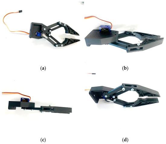
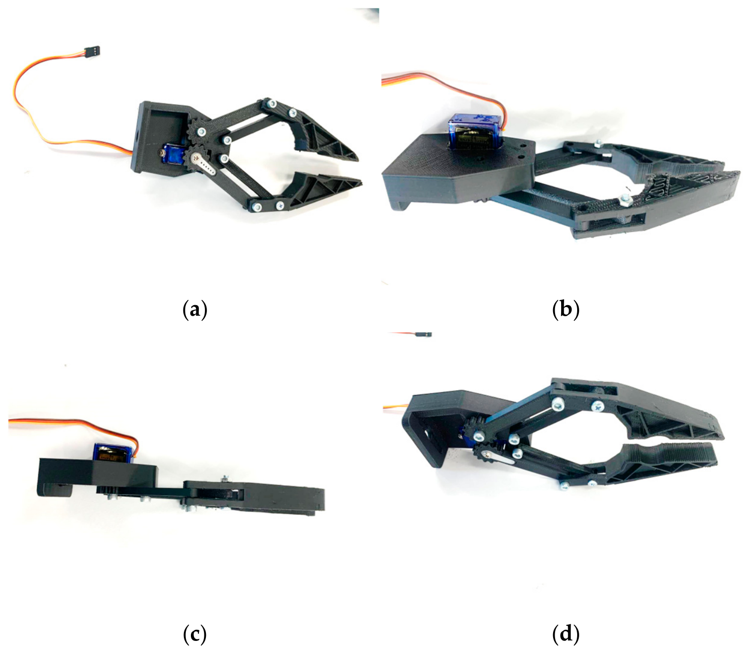
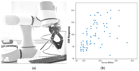
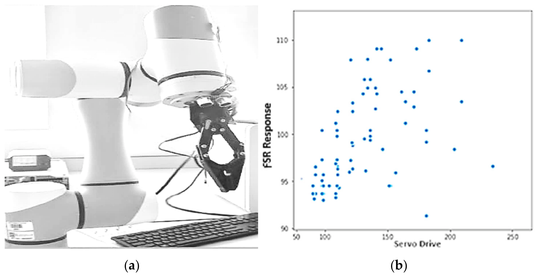
The experiments were conducted using consistent robot and controller settings to enable direct comparison of the three architectures with one prototype shown in Figure 8 and its integration and FSR response in Figure 9. A successful cycle was defined as one in which the object was grasped, transported to the destination without a recorded drop or displacement event, and released as intended. Structural condition was recorded separately through observation of fracture, permanent deformation, visible cracking, and functional degradation.
Figure 8.
Assembled FDM-fabricated gripper prototype and integrated sensing/control hardware viewed from different orientations: (a–d) Prototype views.
Figure 9.
Experimental characterization of the robotic gripper system: (a) integration of the fabricated end-effector with the Dobot CR5 collaborative robot; (b) FSR response as a function of servo actuation.
3.2. Performance Metrics and Data Analysis
The following performance quantities were used:
- Grasp Success Rate: Percentage of successfully completed cycles relative to the 1000 attempted cycles.
- Dropped-Object Events: Observed cumulative number of workpieces dropped or displaced during transportation.
- Structural Outcome: Observed fracture, permanent deformation, visible cracking, or other functional mechanical damage.
- Cycle-Completion Time: Time required to complete one programmed pick-and-place cycle.
- Positioning Variation: Variation in final gripping or placement position over repeated operations.
- Maximum Dynamic Load: Highest experimentally verified external load transported without loss in grasp stability under the specified test procedure.
- Electrical Energy per Cycle: Electrical energy associated with one operating cycle.
3.3. Performance Evaluation Metrics
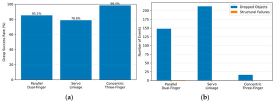
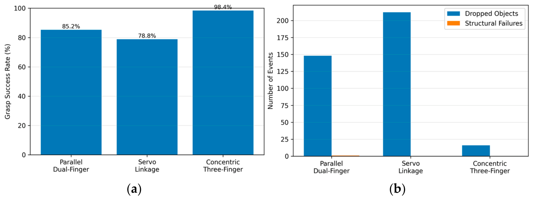
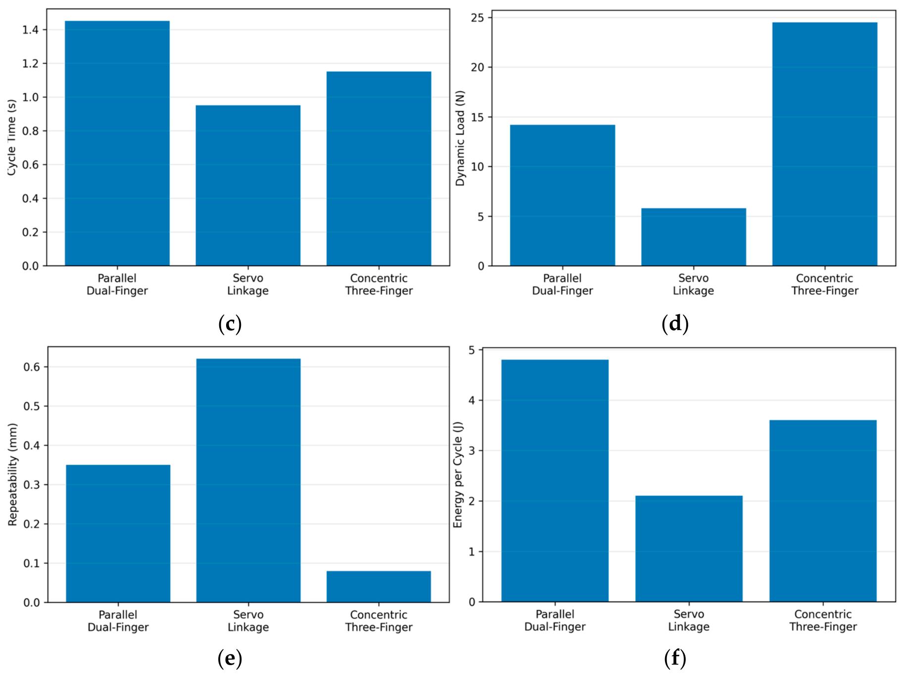
The proposed gripper designs were assessed using quantitative performance indicators commonly employed in robotic manipulation studies as shown in Figure 10. These metrics were selected to evaluate both the mechanical robustness of the gripper designs and their operational effectiveness during repetitive industrial handling tasks.
Figure 10.
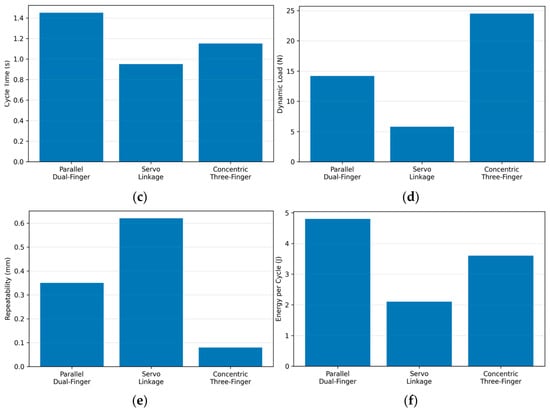
Experimental performance comparison of the three gripper architectures: (a) grasp success rate; (b) dropped-object events over 1000 cycles; (c) cycle-completion time; (d) maximum dynamic load; (e) positioning variation; and (f) electrical energy per cycle. Error bars should be included only where supported by repeated measurements, with the variability measure and sample size defined in the caption.
The primary evaluation metrics included:
- Grasp Success Rate (%): Percentage of successful pick-and-place cycles relative to the total number of experimental trials.
- Object Slippage: Total number of dropped or displaced workpieces during transportation.
- Structural Reliability: Number of observed mechanical failures, including fractured components, excessive deformation, or permanent damage after 1000 operating cycles.
- Cycle Time: Average duration required to complete one pick-and-place operation.
- Grasp Repeatability: Variation in the final gripping position measured over repeated operations.
- Maximum Dynamic Load: Maximum payload that could be transported without loss in grasp stability.
- Energy Consumption: Average electrical energy consumed by the actuator during one complete grasping cycle.
These performance metrics provide a comprehensive assessment of the operational capability, durability, and efficiency of each proposed gripper architecture and establish the basis for the comparative analysis presented in the following section. Findings from Graphical Analysis:
- Radial Force Distribution: The concentric three-finger topology reduces dropped parts by over 92% compared to the linkage-driven alternative. Surrounding objects with 120-degree symmetry converts the holding action from surface friction into structural constraint vectors.
- Structural Durability: Splitting the load path across three planetary contact points keeps localized stress below the shear thresholds of thermoplastic layer structures (PLA/TPU). This protects critical sub-elements from the fatigue fractures seen in traditional rack-and-pinion transmission mechanisms.
4. Results
4.1. Comparative Grasping Performance
Table 2 summarizes the grasp-reliability and structural outcomes obtained from the 1000-cycle experimental sequence for each architecture. The concentric three-finger gripper completed 984 successful cycles, corresponding to a grasp success rate of 98.4%, and recorded 16 dropped-object events. The parallel dual-finger configuration completed 852 successful cycles, corresponding to 85.2%, with 148 dropped-object events. The micro-servo linkage architecture completed 788 successful cycles, corresponding to 78.8%, and recorded 212 dropped-object events.
Table 2.
Grasp reliability and structural outcomes over 1000 pick-and-place cycles per gripper architecture.
Within the investigated workpieces and operating conditions, the concentric three-finger configuration therefore exhibited the highest grasp reliability among the three architectures.
4.2. Structural Reliability
Structural conditions were monitored throughout the 1000-cycle experiment testing and characterization [19,20,21]. The parallel dual-finger gripper experienced one rack-tooth shear failure. The location of the failure was consistent with the rack-tooth region identified as mechanically critical in the numerical structural analysis. The micro-servo linkage configuration completed the test sequence without component fracture, although observable elastic deflection occurred in the slender linkage members during robot motion. The concentric three-finger configuration completed the 1000-cycle experimental sequence without observable fracture, permanent deformation, or visible cracking.
The experimental observations were therefore qualitatively consistent with the predicted locations of structural vulnerability. However, the results do not constitute direct validation of the calculated stress magnitudes and should not be interpreted as a long-term fatigue-life assessment.
4.3. Operational Performance Metrics
Additional operational metrics are summarized in Table 3. The micro-servo linkage architecture exhibited the shortest reported cycle-completion time at 0.95 s. However, it also exhibited the lowest maximum dynamic load of 5.8 N and the largest reported positioning variation of 0.62 mm. The parallel dual-finger architecture exhibited a cycle-completion time of 1.45 s, a maximum dynamic load of 14.2 N, and a positioning variation of 0.35 mm. The concentric three-finger configuration exhibited the highest reported maximum dynamic load of 24.5 N and the smallest reported positioning variation of 0.08 mm. Its reported electrical energy consumption was 3.6 J per cycle.
Table 3.
Additional operational performance metrics of the three gripper architectures.
The interpretation of these quantities depends on the measurement definitions described in Section 3.2.
5. Discussion
5.1. Influence of Mechanical Architecture on Grasp Performance
The experimental testing and characterization [22,23,24] demonstrate substantial differences in grasp performance among the three mechanical configurations. The parallel dual-finger architecture constrains the workpiece primarily through two opposing contacts. Although this arrangement provided adequate performance for the investigated task, it exhibited substantially more dropped-object events than the concentric three-contact configuration. The micro-servo linkage architecture exhibited the lowest grasp success rate despite its comparatively short cycle time. Its lightweight construction reduced moving mass but was accompanied by observable linkage deflection, low maximum dynamic load, and comparatively large positioning variation. The concentric three-finger design provided three circumferentially distributed contact locations separated by approximately 120°. This arrangement is mechanically capable of providing resistance to translation and rotation through multiple contact directions.
The observed experimental performance is consistent with this interpretation. However, the individual fingertip contact forces were not measured independently. The experiments therefore support, but do not directly quantify, the proposed load-distribution mechanism.
5.2. Relationship Between Structural Analysis and Experimental Behavior
The numerical structural analysis predicted different critical regions for the three architectures. The parallel dual-finger mechanism exhibited its highest reported stress near the rack-tooth root, and a rack-tooth failure was observed experimentally. The micro-servo linkage configuration exhibited a high predicted stress around the pin-joint and slender-link regions, and visible elastic deflection was observed experimentally. The concentric three-finger design exhibited the lowest reported peak stress among the three models and completed the 1000-cycle sequence without observable structural failure.
This qualitative correspondence supports the use of the numerical analysis for identifying mechanically vulnerable regions. However, FDM-fabricated PLA can exhibit direction-dependent stiffness and strength because of raster orientation, interlayer bonding, infill structure, and processing conditions. If an isotropic homogeneous material model was used, this represents a simplification of the physical printed structure.
Accordingly, the predicted stress values should primarily be interpreted comparatively rather than as definitive physical failure stresses.
Future work should incorporate experimentally characterized material properties, build-orientation effects, and physical strain or load-deflection measurements.
5.3. Sensor-Assisted Threshold Control
The embedded sensing system provided proximity information from the HC-SR04 and contact-dependent information from the FSR. These measurements were evaluated against predefined thresholds to determine discrete operating states. The system therefore differs from continuous closed-loop force regulation. A desired grasp-force setpoint was not defined, and a continuously updated force-error quantity was not minimized through a feedback controller.
The improved grasp performance of the concentric three-finger architecture should consequently not be attributed to advanced force control. Because the architecture comparison was performed under common sensing and operating conditions, the observed performance differences primarily reflect the combined effects of mechanical configuration, stiffness, contact arrangement, and actuation characteristics.
Future development should include calibration of the FSR response against known applied forces and implementation of continuous force-feedback regulation using a defined grasp-force reference. Such a system would permit quantitative evaluation of force-tracking error, settling time, overshoot, and disturbance rejection.
5.4. Comparison with Recent Robotic-Gripper Research
Contemporary robotic-gripper research includes rigid, compliant, soft, multimaterial, and hybrid architectures. Recent work has demonstrated customized rigid contact geometry, mechanically adaptive multi-finger mechanisms, soft materials, compliant structures, variable stiffness, multimaterial additive manufacturing, and integrated sensing as shown in Table 4.
Table 4.
State-of-the-Art comparison with recent.
These developments demonstrate that FDM fabrication, multi-finger grasping, and sensor integration are established research directions. The contribution of the present study therefore lies primarily in the controlled experimental comparison of three mechanically distinct FDM-fabricated architectures using a common robot platform and experimental protocol. Direct numerical comparison with published grippers nevertheless requires caution. Reported success rate, grasp force, payload, repeatability, cycle time, and energy consumption are strongly dependent on the object set, actuator, trajectory, grasp criteria, and measurement procedure.
Accordingly, the literature values obtained using different protocols should be interpreted as contextual benchmarks rather than direct rankings.
5.5. Manufacturing Implications
FDM provided a practical fabrication route for producing the three geometrically distinct prototype architectures from digital CAD models. The process permits structural geometry, finger shape, mounting interfaces, and contact features to be modified digitally without requiring architecture-specific molds. This makes material-extrusion fabrication suitable for iterative prototype development and low-volume geometric customization. However, the present investigation did not perform a formal techno-economic comparison with commercial or conventionally machined robotic grippers.
Therefore, no quantitative conclusion is drawn regarding manufacturing-cost reduction, lead-time reduction, or production-scale economic advantage unless supported by the fabrication records described in Section 2.2.
Industrial scalability was also outside the experimental scope. Production scalability would depend on printer throughput, material consumption, quality control, operator labor, post-processing requirements, component lifetime, maintenance, and production volume.
The manufacturing contribution demonstrated in the present work is therefore the feasibility of fabricating and experimentally comparing multiple customized end-effector architectures using a common FDM workflow rather than demonstrated economic superiority over other production methods.
5.6. Limitations and Future Work
Several limitations should be considered.
First, the experimental campaign used two polymer workpiece configurations: spherical polypropylene specimens and cylindrical polyethylene specimens. The 1000-cycle experiments provide evidence of comparative grasp reliability and structural performance within this test envelope but do not establish broad adaptability to arbitrary objects. Future validation should include irregular and asymmetric geometries, broader object dimensions and masses, surfaces with different friction and roughness characteristics, compliant and rigid objects, and multiple grasp orientations.
Second, all experiments were conducted using a single Dobot CR5 collaborative robot under controlled robot trajectories, workpiece locations, controller settings, and laboratory conditions. These controls were useful for isolating architecture-dependent performance, but testing on additional robot platforms and under less constrained industrial conditions would be required to establish broader generalizability.
Third, the structural evaluation was limited to the reported numerical load case and a 1000-cycle operational experiment. Longer-duration cyclic testing is needed to investigate fatigue, wear, layer-interface degradation, dimensional change, and component life.
Fourth, the FSR was used as a threshold-based contact sensor rather than a calibrated continuous force sensor. Future work should include force calibration and continuous force-feedback regulation.
Fifth, a dedicated manufacturing assessment should quantify filament consumption, print time, assembly requirements, component cost, printing energy, maintenance, and lifecycle performance before claims regarding economic advantage or industrial scalability are made.
Overall, the concentric three-finger configuration provided the strongest combination of grasp reliability, structural outcome, maximum dynamic load, and positioning performance among the three designs evaluated under the present experimental conditions.
6. Conclusions
This study presented the design, FDM fabrication, integration, and controlled experimental comparison of three lightweight robotic gripper architectures for a Dobot CR5 collaborative robot. The evaluated designs comprised a parallel dual-finger gripper, a micro-servo linkage gripper, and a concentric three-finger gripper. An embedded sensing system incorporating ultrasonic proximity measurement and FSR-based contact feedback was implemented using sensor-feedback-based threshold logic. Each architecture was evaluated over 1000 consecutive pick-and-place cycles using spherical polypropylene and cylindrical polyethylene workpieces under common operating conditions.
Within this experimental envelope, the concentric three-finger architecture achieved the highest grasp success rate at 98.4%, corresponding to 984 successful cycles and 16 dropped-object events. The parallel dual-finger and micro-servo linkage configurations achieved success rates of 85.2% and 78.8%, respectively. The concentric three-finger architecture also completed the test sequence without observable structural fracture or permanent deformation and exhibited the highest reported maximum dynamic load and smallest reported positioning variation among the three configurations.
These findings indicate that the concentric three-contact architecture was the most reliable of the three mechanical configurations for the tested polymer workpieces and operating conditions. The results are consistent with the intended mechanical advantage of distributing object contact around three circumferential locations, although individual finger forces were not directly measured. The study also demonstrates the feasibility of using a common FDM workflow to fabricate and compare alternative end-effector architectures. However, the present work does not establish universal object adaptability, quantified manufacturing-cost reduction, industrial production scalability, long-term fatigue performance, or continuous closed-loop force regulation.
Future work will extend the object set to include irregular geometries, broader payloads, different surface characteristics, and multiple grasp orientations. Longer-duration cyclic testing will investigate wear and fatigue. Calibration of the tactile sensor and implementation of continuous force-feedback control will enable quantitative force-regulation studies. Dedicated manufacturing and lifecycle analyses will be required to assess economic viability and production scalability.
Within these limitations, the results demonstrate that mechanical architecture has a substantial influence on repetitive pick-and-place performance and identify the concentric three-finger configuration as the most promising of the three investigated designs for further development.
Author Contributions
Conceptualization, S.K. and A.K.; methodology, R.D.; software, E.A.-E.; validation, S.K., R.D. and E.A.-E.; formal analysis, A.K.; investigation, A.K.; resources, E.A.-E.; data curation, R.D.; writing—original draft preparation, S.K.; writing—review and editing, R.D.; visualization, E.A.-E.; supervision, S.K.; project administration, S.K.; funding acquisition, n/a. All authors have read and agreed to the published version of the manuscript.
Funding
This research received no external funding.
Institutional Review Board Statement
Not applicable.
Informed Consent Statement
Not applicable.
Data Availability Statement
No new data were created or analyzed in this study.
Conflicts of Interest
The authors declare no conflict of interest.
Appendix A
C++
#include <Servo.h>
//Pin Allocations
const int TRIG_PIN = 3;
const int ECHO_PIN = 2;
const int FORCE_SENSE_PIN = A0;
const int ACTUATOR_A_PIN = 9;
const int ACTUATOR_B_PIN = 10;
const int STABILIZER_PIN = 11;
const int LED_ALERT_PIN = 4;
//Operational Constants & Thresholds
const float STABILIZATION_DIST_CM = 50.0;
const float CRITICAL_DIST_CM = 10.0;
const int FORCE_THRESHOLD_ADC = 450;
//Servo Object Initialization
Servo jointActuatorA;
Servo jointActuatorB;
Servo sensorStabilizer;
void setup() {
pinMode(TRIG_PIN, OUTPUT);
pinMode(ECHO_PIN, INPUT);
pinMode(LED_ALERT_PIN, OUTPUT);
Serial.begin(9600);
jointActuatorA.attach(ACTUATOR_A_PIN, 500, 2500);
jointActuatorB.attach(ACTUATOR_B_PIN, 500, 2500);
sensorStabilizer.attach(STABILIZER_PIN, 500, 2500);
//Default safe state configuration
sensorStabilizer.write(0);
digitalWrite(LED_ALERT_PIN, LOW);
}
float measureTargetDistance() {
digitalWrite(TRIG_PIN, LOW);
delayMicroseconds(2);
digitalWrite(TRIG_PIN, HIGH);
delayMicroseconds(10);
digitalWrite(TRIG_PIN, LOW);
long duration = pulseIn(ECHO_PIN, HIGH, 30000);//30 ms timeout
if (duration == 0) return 999.0;
return duration * 0.01715;
}
void loop() {
//1. Ingest Force Feedback
int rawForceValue = analogRead(FORCE_SENSE_PIN);
//2. Map Primary Positional Command Input from Master Control Calibration
int targetPositionDeg = map(rawForceValue, 0, 1023, 0, 180);
jointActuatorA.write(targetPositionDeg);
delay(15);
//3. Track Object Distance Proximity
float targetDistanceCm = measureTargetDistance();
//4. Closed-Loop Safety Collision and Tactile Grip Management
if (targetDistanceCm < CRITICAL_DIST_CM || rawForceValue > FORCE_THRESHOLD_ADC) {
sensorStabilizer.write(0);
digitalWrite(LED_ALERT_PIN, HIGH);//Engaged grasp alert
} else if (targetDistanceCm < STABILIZATION_DIST_CM) {
sensorStabilizer.write(180);
digitalWrite(LED_ALERT_PIN, LOW);
} else {
sensorStabilizer.write(0);
digitalWrite(LED_ALERT_PIN, LOW);
}
delay(100);//Main loop tracking frequency delay
}
References
- Liu, L.; Guo, F.; Zou, Z. Application, development and future opportunities of collaborative robots (cobots) in manufacturing: A literature review. Int. J. Hum.–Comput. Interact. 2024, 40, 915–932. [Google Scholar] [CrossRef] [Scilit]
- Wu, C.; Zhang, Z.; Wang, Z. A geometric inverse kinematics solution for the dobot CR5. J. Phys. Conf. Ser. 2026, 3193, 012041. [Google Scholar] [CrossRef] [Scilit]
- AboZaid, Y.A.; Aboelrayat, M.T.; Fahim, I.S. Soft robotic grippers: A review on technologies, materials, and applications. Sens. Actuators A Phys. 2024, 372, 115380. [Google Scholar] [CrossRef] [Scilit]
- Kim, D.; Baek, S.R.; Kim, M.S. Design and manufacturing process of pneumatic soft gripper for additive manufacturing. Sens. Actuators A Phys. 2024, 370, 115218. [Google Scholar] [CrossRef] [Scilit]
- Trinh, H.X.; Nguyen, H.H.; Pham, T.D. A novel rigid-soft gripper for safe and reliable object handling. J. Braz. Soc. Mech. Sci. Eng. 2024, 46, 176. [Google Scholar] [CrossRef] [Scilit]
- Zaidi, S.; Maselli, M.; Laschi, C. Actuation technologies for soft robot grippers and manipulators: A review. Curr. Robot. Rep. 2021, 2, 355–369. [Google Scholar] [CrossRef] [Scilit]
- Goh, D.J.S.; Goh, G.L.; Sivarajan, S. Design Optimization of a Variable Stiffness Robotic Gripper with Passive Restoration Fabricated by Multimaterial 3D Printing. Adv. Robot. Res. 2026, 2, e202500054. [Google Scholar] [CrossRef] [Scilit]
- Yumbla, F.; Quinones, Y.E.; Mendoza, E. An open-source 3D printed three-fingered robotic gripper for adaptable and effective grasping. Biomimetics 2025, 10, 26. [Google Scholar] [CrossRef] [Scilit] [PubMed]
- Mun, H.; Cortes, D.D.S.; Youn, J.H. Multi-degree-of-freedom force sensor incorporated into soft robotic gripper for improved grasping stability. Soft Robot. 2024, 11, 628–638. [Google Scholar] [CrossRef] [Scilit] [PubMed]
- DOBOT Robotics. DOBOT CR5 Collaborative Robot Platform Specifications; DOBOT Corporation: Shenzhen, China, 2015; Available online: https://www.dobot-robots.com/products/cr-series/cr5.html (accessed on 15 July 2026).
- Robot arm Two-Finger Gripper by Mczapla—Thingiverse. Available online: https://www.thingiverse.com/thing:7130255 (accessed on 15 September 2025).
- Robot Gripper 9g Micro Servo by Yisparyan—Thingiverse. Available online: https://www.thingiverse.com/thing:715525 (accessed on 15 October 2025).
- Circular Robotic Gripper by Alex30—Thingiverse. Available online: https://www.thingiverse.com/thing:4656317 (accessed on 15 August 2025).
- Xin, Y.; Yangyang, L. The critical role of additive material workflows and thermoplastic poly-mers in soft industrial gripper design. Adv. Mater. 2024, 36, 2307963–2307971. [Google Scholar]
- Kafumbe, S.M.M. Fabrication of a micro-cantilever gold plated beams array. Microelectron. Int. 2013, 31, 8–23. [Google Scholar] [CrossRef] [Scilit]
- Kuang, L.; Lou, Y.; Song, S. Design and fabrication of a novel force sensor for robot grippers. IEEE Sens. J. 2017, 18, 1410–1418. [Google Scholar] [CrossRef] [Scilit]
- Kafumbe, S.M.M.; Kundaeli, H.N.; Aldalaien, M. A Microprocessor Controlled Population Counter. Univers. J. Electr. Electron. Eng. 2014, 2, 222–233. [Google Scholar] [CrossRef] [Scilit]
- Arduino Systems. Arduino Microcontroller Core Reference Guide; Open-Source Hardware Registry Document v1.4. 2010. Available online: https://www.arduino.cc/en/Main/ArduinoBoardUno (accessed on 18 May 2026).
- Kumar, V.; Fontul, M.; Neves, C. Prototyping and Characterization of Gripper Technologies for Stiff Fabric Material. IEEE Access 2025, 13, 107890–107916. [Google Scholar] [CrossRef] [Scilit]
- Kafumbe, S.; Harris, A.; Burdess, J. Testing and characterization of a MEMS micro-cantilever system. In Proceedings of the IEEE 59th International Midwest Symposium on Circuits and Systems (MWSCAS), Abu Dhabi, United Arab Emirates, 16–19 October 2016. [Google Scholar]
- El-Sayed, A.M. A novel design and testing of force-sensorised robotic fingers for stable grasping of high value crops. Measurement 2026, 290, 121707. [Google Scholar] [CrossRef] [Scilit]
- Su, Y.; Lueth, T.C.; Sun, Y. Design of a one-shot FDM-printed adaptive robotic gripper with rigid–flexible hybrid fingers. Mechatronics 2026, 116, 103482. [Google Scholar] [CrossRef] [Scilit]
- Hussain, I.; Malvezzi, M.; Gan, D. Compliant gripper design, prototyping, and modeling using screw theory formulation. Int. J. Robot. Res. 2021, 40, 55–71. [Google Scholar] [CrossRef] [Scilit]
- Muktadir, M.A.; Sun, Y.; Amelia, M.; Elliott, M.A. Design of robot grippers for binder jet products handling. Sci. Rep. 2024, 14, 5750. [Google Scholar] [CrossRef] [Scilit] [PubMed]

Disclaimer/Publisher’s Note: The statements, opinions and data contained in all publications are solely those of the individual author(s) and contributor(s) and not of MDPI and/or the editor(s). MDPI and/or the editor(s) disclaim responsibility for any injury to people or property resulting from any ideas, methods, instructions or products referred to in the content. |
© 2026 by the authors. Licensee MDPI, Basel, Switzerland. This article is an open access article distributed under the terms and conditions of the Creative Commons Attribution (CC BY) license.