


Abstract
Automated inspection of small metallic components is increasingly required in industrial manufacturing, particularly when dimensional conformity and geometric characteristics affect assembly quality and functional performance. This paper presents a preliminary proof-of-concept study for a collaborative SCARA-based platform intended for automated dimensional and geometric inspection of metallic plates. The study does not report a complete metrologically validated inspection cell; instead, it defines the industrial inspection problem, proposes a modular robotic architecture, and documents the preliminary implementation activities already completed. The industrial motivation is associated with metallic plates used in automotive thermal-management components, while a simplified rectangular plate is adopted for controlled development of handling, positioning, image acquisition, calibration, and initial dimensional-feature extraction. The proposed architecture separates robotic manipulation from the measurement subsystem: the SCARA robot provides repeatable handling and positioning, whereas the vision system supports preliminary calibrated in-plane measurement. The robotic platform is based on the PSR-20 collaborative SCARA robot (SmileTech, Portugal), selected due to its compact footprint, repeatable planar motion, affordable cost and suitability for automated pick-and-place inspection tasks. The implemented activities include SCARA workspace simulation, end-effector design, camera integration, intrinsic camera calibration, measurement-plane calibration, and preliminary calibrated 2D dimensional measurements. The experimental validation reported in this study is currently limited to in-plane measurements of length and width. Height, thickness, flatness, and surface-form inspection are identified as future extensions and have not yet been experimentally validated. The results show repeatable measurements under the tested conditions for a high-contrast reference part, while the representative metallic part remains limited by segmentation robustness and contour-definition uncertainty. Remaining work includes a formal uncertainty analysis, broader validation with calibrated reference artefacts, robust segmentation, and out-of-plane sensing.
1. Introduction
Modern manufacturing lines must verify whether metal parts meet dimensional and geometric requirements at production-compatible speeds and with limited operator dependence. This is particularly relevant in the automotive sector, where small metallic components may affect assembly quality, sealing, support stability, thermal performance, and functional reliability. Inspection may therefore involve not only nominal dimensions, but also geometric characteristics such as height variation, thickness variation, surface profile, and flatness-related features.
Manual inspection using gauges, mechanical fixtures, and conventional measuring instruments remains common, but it depends strongly on operator skill, part placement consistency, and repetitive execution. These factors may limit repeatability, traceability, scalability, and integration with automated production workflows. Robotic automation can reduce part-handling variability and enable more systematic inspection cycles, although its metrological value depends on the combined performance of the robot, sensor, calibration procedure, referencing strategy, and data-processing chain.
Several approaches can be used for dimensional and geometric inspection. Contact metrology provides reliable reference measurements, but it is often slower and less suited to high-throughput inspection [1,2]. Two-dimensional vision systems are flexible for contour-based measurements, but are limited when out-of-plane features are relevant [3,4]. Three-dimensional scanning, laser triangulation, and structured-light methods can provide denser geometric information for sheet-metal, flatness, thickness, and surface-form inspection, although they introduce additional calibration, surface-property, and uncertainty challenges [5,6,7,8,9,10,11,12,13]. Robotic inspection systems combine automation with sensing, but final performance depends on the complete system rather than on any single component [12,14]. Recent surveys also identify collaborative robotics and computer vision as important directions for flexible industrial inspection, while emphasizing robust calibration, sensing, and perception strategies [15].
Among industrial robot architectures, collaborative SCARA robots are particularly suitable for automated inspection of small planar components because they provide compact workspaces, repeatable planar motion, vertical approach capability, and straightforward integration with vision-based inspection systems. Compared with Delta robots, which are typically optimized for high-speed lightweight pick-and-place operations, SCARA robots provide a practical compromise between manipulation speed, positioning repeatability, and inspection-cell simplicity. Previous work by the authors has also investigated the development and benchmarking of collaborative robotic platforms based on Delta architectures [16].
This paper presents a preliminary proof-of-concept study for an automated dimensional and geometric inspection platform based on a collaborative SCARA robot. The objective is not to claim a complete industrial inspection system or a validated geometric inspection capability, but to define the inspection problem, propose a modular robotic architecture, and report the preliminary development activities already carried out. The experimental validation reported here is currently limited to calibrated in-plane measurements of length and width. The main contributions are the formulation of inspection requirements for a representative metallic plate, the proposal of a SCARA-based inspection architecture, the preliminary development of robot simulation, workspace assessment, gripper design, and camera integration, and the demonstration of a calibrated 2D vision-processing workflow for part detection and dimensional-feature extraction. Height, thickness, flatness, and surface-form inspection remain future extensions.
2. Inspection Problem and Requirements
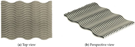
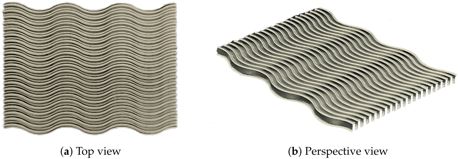
The work is motivated by an industrial scenario involving metallic plates used in automotive thermal-management components, such as EGR coolers and intercoolers. These components require dimensional consistency and controlled geometric behavior because local deviations may affect assembly, contact conditions, sealing performance, and functional reliability. The representative metallic component motivating the study is shown in Figure 1.
Figure 1.
Representative metallic component motivating the inspection problem.
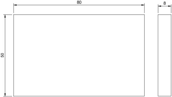
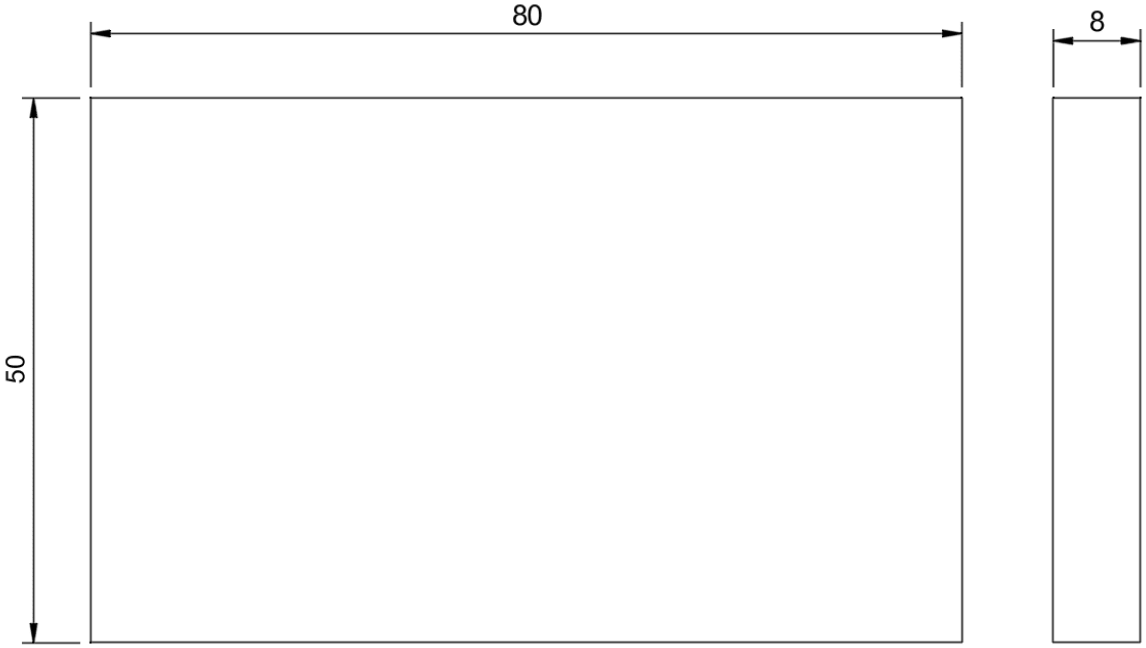
At the current stage, the complete industrial geometry is not addressed experimentally. Instead, a simplified rectangular plate is adopted to support controlled development of handling, positioning, image acquisition, and initial dimensional processing. This simplification reduces technical risk and allows the robotic and vision subsystems to be developed before moving to the more complex industrial component.
The simplified plate, shown in Figure 2, has nominal dimensions of .
Figure 2.
Technical drawing of the simplified rectangular plate adopted for the preliminary development stage. Nominal dimensions are given in millimetres.
The inspection characteristics considered in this proof-of-concept are length and width as the currently implemented in-plane dimensional characteristics, while height or thickness and flatness-related deviations are retained as future requirements. Length and width can be approached using image-based contour extraction. Height and thickness are out-of-plane dimensional characteristics and require additional referencing or sensing, particularly when metallic plates or corrugated geometries are involved [10,11]. Flatness is considered only as a future requirement for planar functional surfaces of the simplified plate and is not yet implemented experimentally. More complex surface-form requirements associated with the real corrugated metallic component are outside the current experimental scope and will require later geometric validation [8,9,17]. The representative corrugated component motivating the study is therefore not fully addressed experimentally at this stage. This staged definition allows the robotic manipulation, calibration procedures, and 2D measurement algorithms to be independently developed before addressing the considerably more complex industrial geometry.
3. SCARA-Based Inspection Platform
The proposed inspection platform is based on the PSR-20 collaborative SCARA robot developed by SmileTech (Portugal). The robot provides four degrees of freedom and was selected due to its compact mechanical structure, repeatable planar motion, and suitability for automated pick-and-place operations involving relatively small metallic components. The proposed system is conceived as a modular robotic inspection platform in which the SCARA robot provides part handling and positioning, while the measurement subsystem performs data acquisition and, at the current stage, calibrated 2D dimensional analysis. Future geometric analysis will require additional out-of-plane sensing and validation. This separation is intentional: the robot is not treated as the measuring instrument itself, but as the element that improves repeatability, reduces operator dependence, and enables automated inspection cycles.
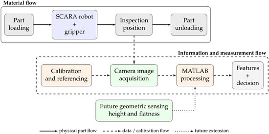
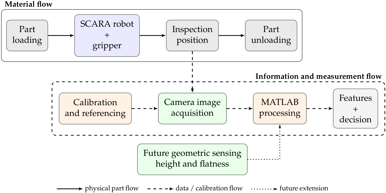
The intended cycle consists of grasping the part, positioning it in the inspection position, acquiring image or sensor data, processing the data, making a conformity decision, and unloading the part. The architecture therefore includes the robot, end-effector, part loading and unloading locations, inspection position, camera, calibration, processing unit, and future geometric sensing module, as summarized in Figure 3.
Figure 3.
Conceptual architecture and workflow of the proposed SCARA-based inspection platform.
The inspection cycle is intentionally modular. The robot is exclusively responsible for repeatable manipulation and positioning, whereas all dimensional measurements are performed by an independently calibrated vision subsystem. This modularity allows future sensing technologies to be incorporated without modifying the robotic manipulation strategy.
A SCARA robot was selected because this architecture is suitable for fast horizontal positioning, repetitive pick-and-place operations, and compact workspaces. SCARA robots are widely used in industrial manipulation tasks because they combine high-speed planar motion with a vertical axis suitable for approach, grasping, and placement operations [18]. Their kinematic structure is therefore appropriate for moving plate-like parts between predefined locations while maintaining a compact inspection layout. Recent work on SCARA-based automation also shows the relevance of integrating these robots with digital and sensing infrastructures for flexible industrial operation [19]. In the proposed cell, the robot is responsible for repeatable manipulation and positioning, whereas the measurement result depends on the sensing, calibration, referencing, and processing subsystems.
4. Preliminary Implementation and Vision-Based Processing
4.1. Robot Simulation and Workspace Assessment
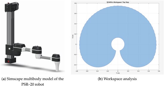
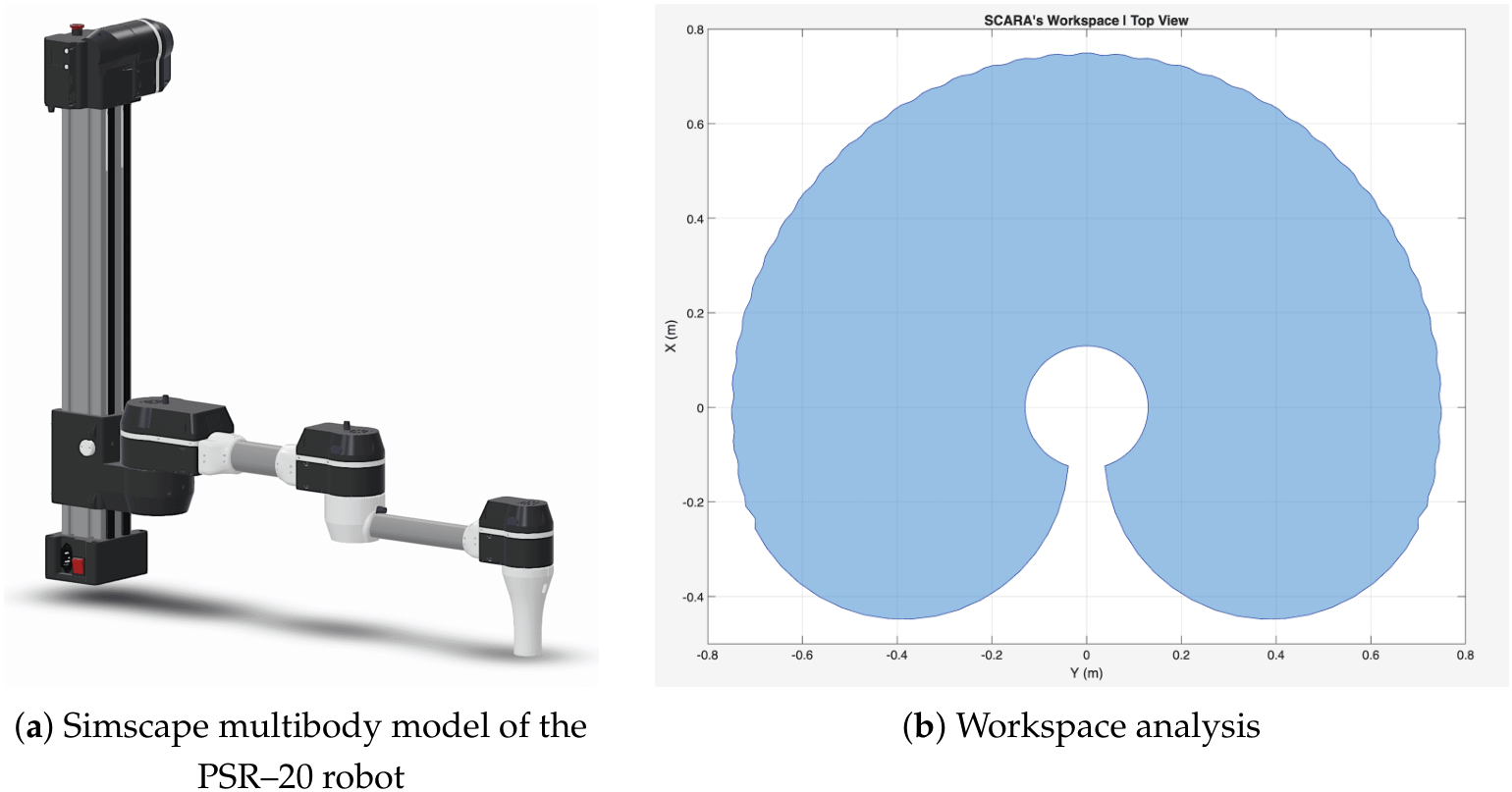
A digital model of the PSR–20 robot was developed in Simscape Multibody/MATLAB R2025b to support the preliminary design of the inspection cell. The virtual prototype allows the evaluation of workspace coverage, reachability, loading and unloading locations, collision-free trajectories, and candidate inspection positions before physical implementation.
The simulated model and workspace analysis are shown in Figure 4. The workspace plot is represented in metres, and the vertical prismatic axis of the SCARA model varies from 0 to . This step supports the definition of candidate loading, inspection, and unloading positions and helps identify whether target positions are reachable without violating joint limits.
Figure 4.
Preliminary SCARA simulation: (a) Simscape Multibody model and (b) simulated workspace, represented in metres, used to assess reachability for inspection-related positioning. The vertical prismatic axis of the simulated model varies from 0 to .
Besides workspace visualization, the virtual model provides a flexible engineering tool for future optimization of inspection-cell layout, cycle planning, robot trajectories, camera positions, and sensing configurations. Virtual multibody models also provide a suitable framework for future studies involving structural flexibility, vibration behaviour, dynamic response, and robot performance optimization before physical implementation, as demonstrated in previous multibody dynamic investigations [20]. This approach is consistent with recent SCARA digital-twin simulation studies, where virtual–physical synchronization and modular communication were used to reduce robot-algorithm testing costs and support safer development before deployment on the real platform [21].
4.2. End-Effector and Camera Integration
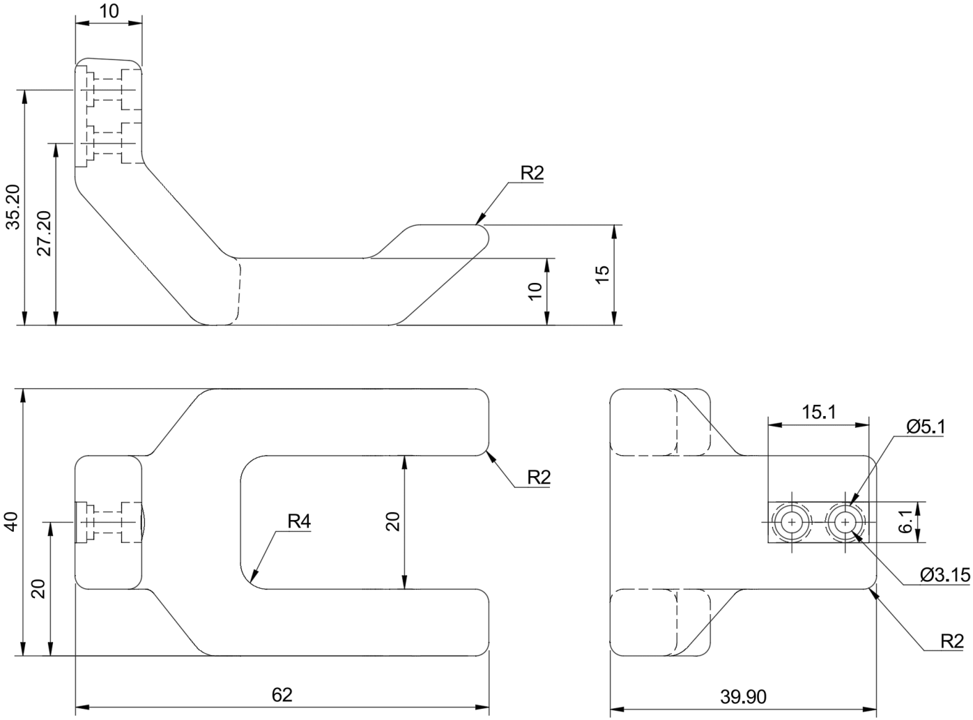
The end-effector was developed to enable stable handling of the simplified plate and integration of the camera. Its design requirements include mechanical compatibility with the part geometry, secure grasping without excessive deformation, unobstructed access to the region of interest, compatibility with the robot flange, and sufficient rigidity for repeated operation.
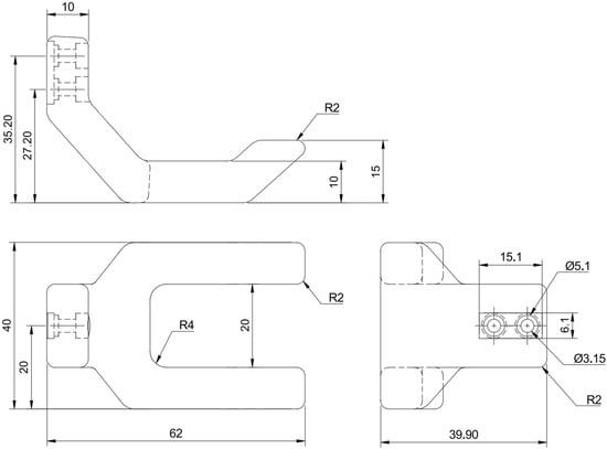
Figure 5 presents the technical drawing of the developed gripper, where all dimensions are given in millimetres. The geometry was defined to ensure stable grasping of the plate while preserving clearance for image acquisition and minimizing interference between the gripping mechanism and the camera field of view.
Figure 5.
Technical drawing of the developed gripper used for plate handling.
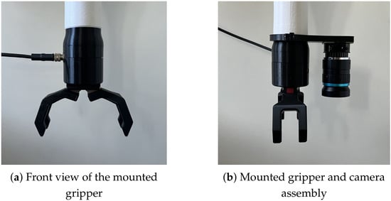
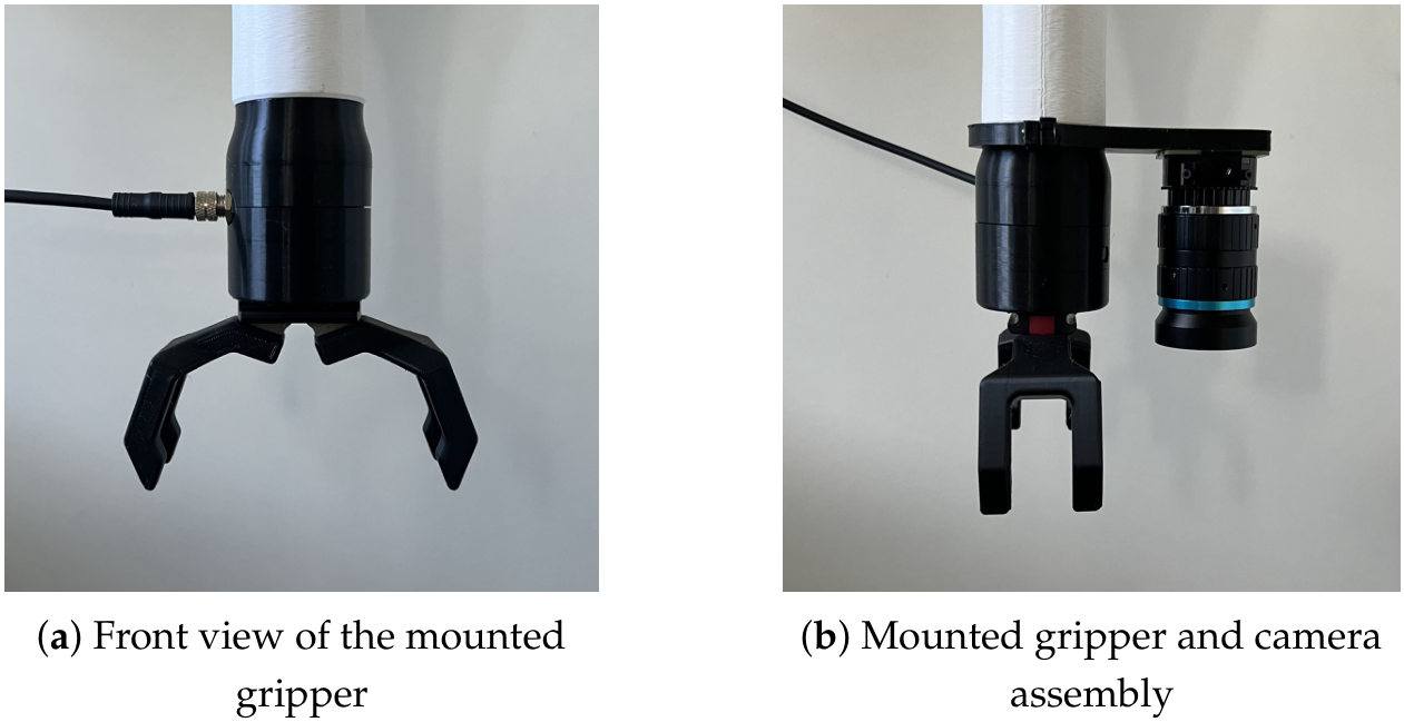
The physical implementation of the end-effector and the camera integration are shown in Figure 6. The mounted configuration demonstrates the feasibility of combining the gripping device and the vision system on the robot end-effector, while maintaining a compact arrangement for handling and image acquisition.
Figure 6.
Physical implementation of the end-effector and camera integration.
Camera integration at the robot end-effector is also relevant for future robot-camera calibration, since camera models mounted on the effector can support automated calibration procedures for industrial robotic manipulators [22].
Although the current implementation demonstrates the feasibility of the proposed mechanical integration, further work is still required to refine the end-effector design, including dimensional optimization, improved mechanical finishing, and evaluation of gripping repeatability under repeated operation. Future design iterations may also focus on manufacturing quality, dimensional accuracy, and structural performance, following practices commonly adopted during the development and validation of additively manufactured engineering components [23]. If increased stiffness, strength, or durability becomes necessary for future industrial applications, metal additive manufacturing may provide a suitable alternative for the fabrication of the end-effector.
4.3. Camera Calibration and Preliminary Vision-Based Measurement
The vision-based measurement stage was developed in three steps: intrinsic camera calibration, measurement-plane calibration, and dimensional extraction from the segmented contour. The objective was to convert image information into metric coordinates on the measurement plane and assess the preliminary dimensional capability of the system.
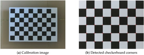
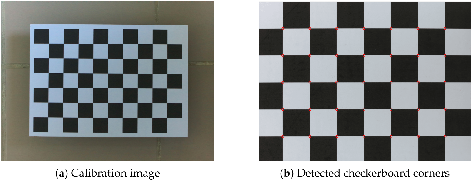
The camera was intrinsically calibrated using a planar checkerboard target to estimate focal length, principal point, radial distortion, and tangential distortion. A set of 22 checkerboard images was acquired under different positions and orientations. The calibration achieved a mean reprojection error of px. Figure 7 shows the calibration target and an example of detected corner points.
Figure 7.
Checkerboard-based camera calibration: (a) acquired calibration image and (b) detected checkerboard corners.
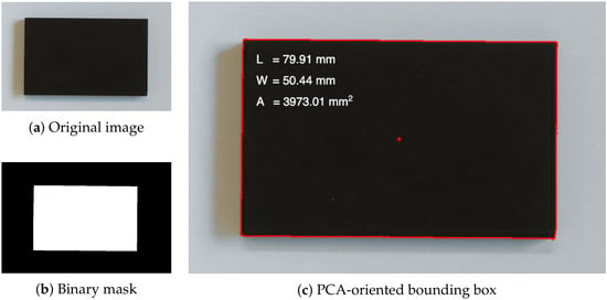
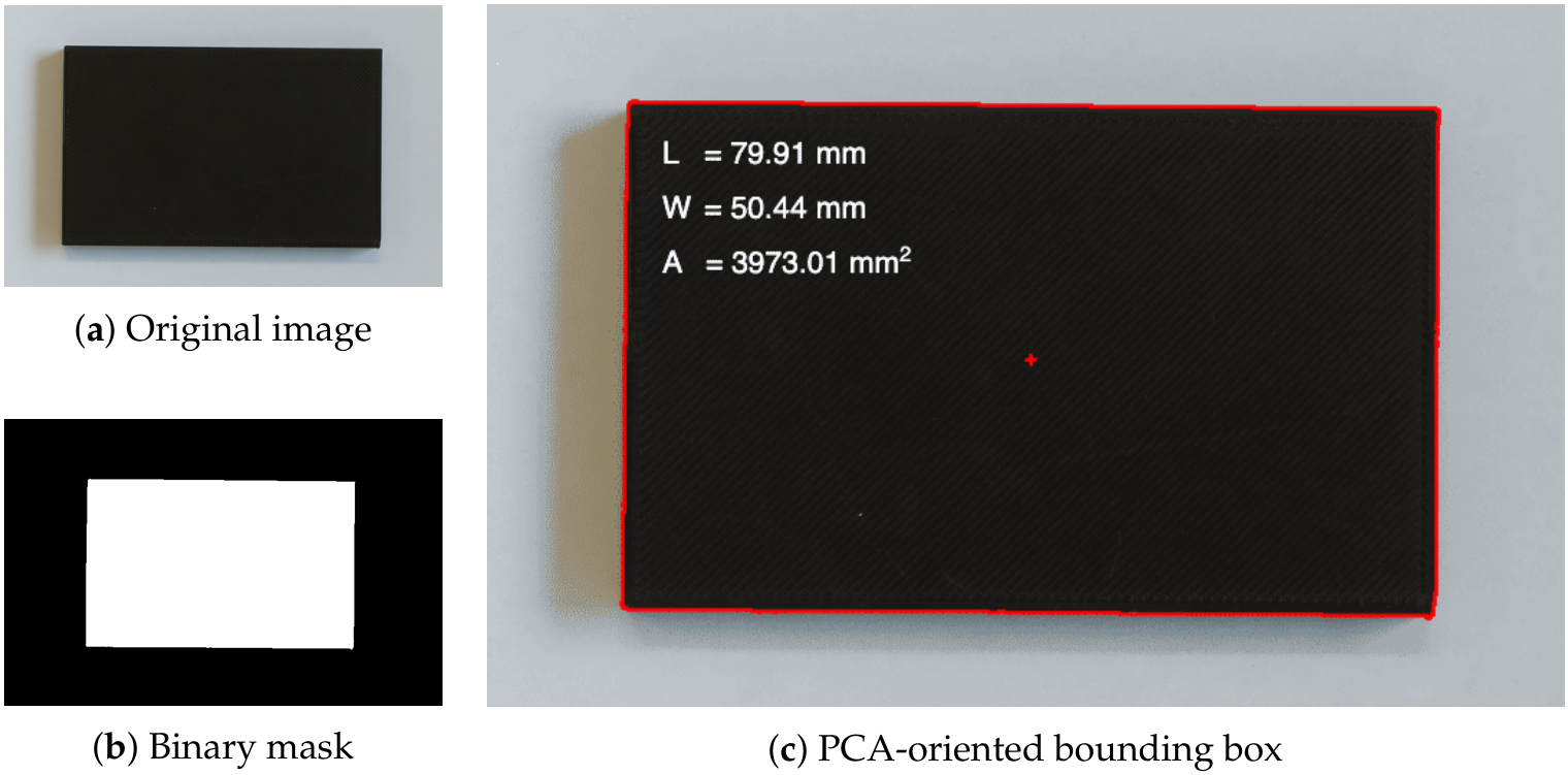
Since intrinsic calibration does not directly provide metric coordinates on the part plane, a second calibration step was performed. A checkerboard was placed at the same height as the upper surface of the inspected part, and a projective transformation was estimated between image points and checkerboard coordinates in millimetres. This was necessary because the apparent image scale depends on the relative height between the calibrated plane and the measured surface. The measurement-plane calibration detected 40 points and produced a mean homography error of , with a maximum error of . These calibration errors are useful diagnostics of the calibration procedures, but they do not represent the complete uncertainty of the dimensional measurement chain. Dimensional measurements were then performed by segmenting the part, transforming the extracted contour into metric coordinates, and computing an oriented bounding box using principal component analysis (PCA). The resulting workflow is shown in Figure 8.
Figure 8.
Preliminary vision-based dimensional measurement workflow: (a) original image, (b) binary mask, and (c) PCA-oriented bounding box used to estimate the in-plane dimensions.
A limited first validation was carried out using a high-contrast rectangular reference part measured with a manual vernier caliper with a stated resolution of , giving . After recalibrating the measurement plane at the height of the upper surface of the part, a single measurement provided for length and for width, corresponding to errors of and . This confirmed the importance of calibrating the measurement plane at the correct height, but the single measurement does not constitute a complete accuracy or uncertainty characterization. The stated resolution characterizes the reading increment only and is not equivalent to the complete uncertainty of the reference measurement.
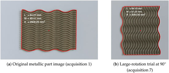
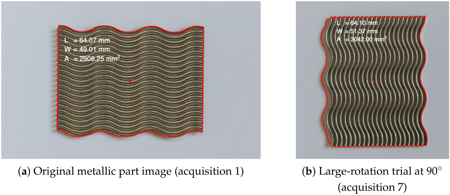
Repeatability was assessed for both the high-contrast black part and the representative metallic wavy part under two conditions: repeated acquisition without moving the part and acquisition after part removal and repositioning. For the metallic part, two additional trials with rotations of approximately and were acquired. The excluded trial indicates that contour extraction under large orientation changes is currently a more important limitation than the calibrated image-to-plane transformation or the nominal robotic positioning strategy.
The main dimensional results are summarized in Table 1.
Table 1.
Summary of preliminary dimensional measurement results using the PCA-oriented bounding box.
The black reference part remained stable even under repositioning, supporting repeatability of the PCA-oriented bounding box for high-contrast contours under the tested conditions. In contrast, the metallic part showed larger dimensional errors, mainly due to contour-definition uncertainty. The image identified as acquisition 7 in Figure 9 was excluded from the nominal repositioning statistics because it corresponded to the approximately robustness test and produced evident segmentation degradation.
Figure 9.
Preliminary segmentation of the representative metallic wavy part under different orientations: (a) nominal orientation and (b) large-rotation robustness trial at .
These results indicate that the calibrated 2D pipeline is suitable for preliminary measurement under controlled visual conditions, but also show that segmentation is the dominant limitation for textured metallic parts. Reflections, internal grooves, shadows, and orientation-dependent appearance changes can alter the detected contour. For the metallic component, the vision system measures the projected envelope of the segmented mask, whereas the caliper measures physical contact distances. These definitions do not necessarily coincide for corrugated or irregular boundaries, which further limits the interpretation of the reported errors.
5. Discussion
The preliminary results support the feasibility of the proposed SCARA-based inspection architecture and provide an initial quantitative assessment of the vision-based measurement chain. The robot, end-effector, and camera integration establish the physical basis for automated image acquisition, while the intrinsic and measurement-plane calibrations enable image coordinates to be interpreted in metric units on the calibrated plane.
For the high-contrast rectangular reference part, the PCA-based measurement strategy showed good repeatability under the tested conditions, with standard deviations below for length and below for width, even with part repositioning. However, the remaining systematic errors of approximately –, together with the limited number of tested parts and reference measurements, show that these standard deviations must not be interpreted as a complete measurement uncertainty. A rigorous uncertainty analysis should include calibration contributions, contour-extraction variability, reference-instrument uncertainty, part repositioning, and the distinction between repeatability and reproducibility. Further validation with calibrated reference artefacts and a larger experimental sample is therefore required before claiming metrological performance.
The metallic wavy part produced larger deviations, approximately –, mainly due to segmentation uncertainty, reflections, internal grooves, shadows, and the difference between optical envelope measurement and caliper contact measurement. Therefore, for the metallic component, the main limitation is currently contour definition rather than robotic positioning alone. The approximately trial further confirmed that substantial changes in part orientation may degrade segmentation and should be addressed in future work through improved lighting, fixturing, orientation control, or more robust segmentation methods.
Recent work on real-world noisy-image denoising likewise highlights that unknown camera-noise characteristics and appearance or style variability pose challenges for robust image processing and generalization [24].
Several limitations must be acknowledged. First, the simplified plate does not reproduce the complete geometry of the industrial metallic component, which was used only to motivate the inspection problem and was not fully validated experimentally. Second, the dimensional validation is based on a limited number of parts and reference measurements. Although the calibrated 2D measurements are repeatable for the high-contrast reference part, a complete uncertainty budget is still required, including calibration, segmentation, reference measurement, repositioning, and environmental contributions. Third, the metallic part shows errors of approximately –, and the approximately trial reveals that contour extraction is currently the dominant limitation. Fourth, height, thickness, flatness, and surface-form inspection have not yet been implemented experimentally. These tasks will require calibrated out-of-plane measurement, suitable reference instruments, and uncertainty analysis. Finally, if the robot is later introduced as an active element of the measurement chain, additional error sources such as pose repeatability, vibration, compliance, and referencing variability must be evaluated.
6. Conclusions
This paper presented a preliminary proof-of-concept study for a collaborative SCARA-based platform intended for automated dimensional and geometric inspection of metallic plates. The work focused on defining the industrial inspection problem, proposing a modular inspection architecture, and documenting the first implementation activities, including SCARA simulation, workspace analysis, end-effector development, camera integration, camera calibration, measurement-plane calibration, and preliminary image-based extraction of length and width. The experimental validation reported in this study is limited to calibrated in-plane dimensional measurements; height, thickness, flatness, and surface-form inspection remain future extensions.
The results indicate that the proposed architecture is technically feasible at the current development stage. The calibrated 2D measurement pipeline showed repeatability under the tested conditions for a high-contrast rectangular reference part, with standard deviations below , but residual systematic errors of approximately – and the limited validation sample prevent a complete metrological claim. The metallic wavy part revealed larger errors of approximately –, primarily associated with segmentation and contour-definition uncertainty rather than with robotic positioning. The system is therefore not yet a complete metrologically validated inspection cell.
Future work will focus on refining the workspace analysis, improving the segmentation of textured metallic parts, increasing the number of tested parts and reference measurements, developing a complete uncertainty budget, and validating the 2D measurement pipeline with calibrated reference artefacts. Only after this dimensional chain has been further validated should an out-of-plane measurement strategy for height, thickness, flatness, and surface form be developed using laser triangulation or other calibrated 3D sensing methods.
Overall, the study establishes a coherent engineering basis for progressing from robotic handling and calibrated image acquisition toward a validated automated inspection system.
Author Contributions
Conceptualization, A.R.C.R.V., C.M.A.V., F.A.V.F. and A.M.S.C.; methodology, A.R.C.R.V. and C.M.A.V.; software, A.R.C.R.V. and F.A.V.F.; validation, A.R.C.R.V., F.A.V.F. and C.M.A.V.; formal analysis, A.R.C.R.V. and C.M.A.V.; investigation, A.R.C.R.V.; resources, C.M.A.V. and A.M.S.C.; data curation, A.R.C.R.V.; writing—original draft preparation, A.R.C.R.V.; writing—review and editing, A.R.C.R.V. and C.M.A.V.; funding acquisition, C.M.A.V. and A.M.S.C. All authors have read and agreed to the published version of the manuscript.
Funding
This research received no external funding.
Data Availability Statement
The original contributions presented in this study are included in the article. Further inquiries can be directed to the corresponding author.
Acknowledgments
The authors gratefully acknowledge the funding provided by the Foundation for Science and Technology (FCT), Portugal, through the Research Unit in Materials, Energy and Environment for Sustainability (proMetheus) at the Polytechnic Institute of Viana do Castelo (IPVC), Viana do Castelo, Portugal, and through the Centre for Mechanical Technology and Automation (TEMA) at the University of Aveiro, Aveiro, Portugal. Additional support was provided within the scope of the project “Agenda DRIVOLUTION: Transition to the Factory of the Future” (project no. C632394276-0046698; operation code 02/C05-i01.02/2022.PC644913740-00000022), under the Agendas/Mobilizing Alliances for Reindustrialization initiative of the Portuguese Recovery and Resilience Plan (PRR).
Conflicts of Interest
Fernando A. V. Figueiredo is affiliated with Smile.Tech Robótica, manufacturer of the SCARA robot used in this study. The remaining authors declare no conflicts of interest.
References
- AlMutairi, A.M.; AlJamaan, F.A.; Ahmed, K.M. Axial, Volumetric and Roundness Performance Verification of Coordinate Measuring Machine (CMM) with Comparative Study Utilizing Two Different Stylus Tip Materials. Measurement 2026, 263, 120072. [Google Scholar] [CrossRef] [Scilit]
- Mohammad, A.; Aljamaan, F.; Bin Shuqayr, S.; Ahmed, K.M. Coordinate Measuring Machine (CMM) Performance Verification Using Standard Step Gauges with New Measurement Model and Modified Uncertainty Analysis. Meas. Sens. 2025, 38, 101658. [Google Scholar] [CrossRef] [Scilit]
- Kumar, P.; Nangai, N.M.B. Exploring the Efficacy of Python-Driven Automated Machine Vision Algorithms for Inspection in Sheet Metal Forming. Exp. Tech. 2025, 49, 703–726. [Google Scholar] [CrossRef] [Scilit]
- Yun, J.P.; Shin, W.C.; Koo, G.; Kim, M.S.; Lee, C.; Lee, S.J. Automated Defect Inspection System for Metal Surfaces Based on Deep Learning and Data Augmentation. J. Manuf. Syst. 2020, 55, 317–324. [Google Scholar] [CrossRef] [Scilit]
- Guo, J.; Tan, D.; Guo, S.; Chen, Z.; Liu, R. Digital Inspection Technology for Sheet Metal Parts Using 3D Point Clouds. Sensors 2025, 25, 4827. [Google Scholar] [CrossRef] [Scilit] [PubMed]
- Zhang, Z.; Shi, G.; Hou, L.; Zhou, L. Geometric Dimension and Imperfection Measurements of Box-T Section Columns Using 3D Scanning. J. Constr. Steel Res. 2021, 183, 106742. [Google Scholar] [CrossRef] [Scilit]
- Cuesta, E.; Meana, V.; Álvarez, B.J.; Giganto, S.; Martínez-Pellitero, S. Metrology Benchmarking of 3D Scanning Sensors Using a Ceramic GD&T-Based Artefact. Sensors 2022, 22, 8596. [Google Scholar] [CrossRef] [Scilit] [PubMed]
- Molleda, J.; Usamentiaga, R.; García, D.F. On-Line Flatness Measurement in the Steelmaking Industry. Sensors 2013, 13, 10245–10272. [Google Scholar] [CrossRef] [Scilit] [PubMed]
- Mao, Z.; Zhang, C.; Guo, B.; Xu, Y.; Kong, C.; Zhu, Y.; Xu, Z.; Jin, J. The Flatness Error Evaluation of Metal Workpieces Based on Line Laser Scanning Digital Imaging Technology. Photonics 2023, 10, 1333. [Google Scholar] [CrossRef] [Scilit]
- Sardellitti, A.; Di Capua, G.; Laracca, M.; Tamburrino, A.; Ventre, S.; Ferrigno, L. A Fast ECT Measurement Method for the Thickness of Metallic Plates. IEEE Trans. Instrum. Meas. 2022, 71, 6004712. [Google Scholar] [CrossRef] [Scilit]
- Wu, C.; Chen, B. An Automatic Measurement System for the Wall Thickness of Corrugated Plate Based on Laser Triangulation Method. Adv. Eng. Inform. 2023, 55, 101814. [Google Scholar] [CrossRef] [Scilit]
- Swojak, N.; Wieczorowski, M.; Jakubowicz, M. Assessment of Selected Metrological Properties of Laser Triangulation Sensors. Measurement 2021, 176, 109190. [Google Scholar] [CrossRef] [Scilit]
- Brosed, F.J.; Aguilar, J.J.; Santolaria, J.; Lázaro, R. Geometrical Verification Based on a Laser Triangulation System in Industrial Environment. Effect of the Image Noise in the Measurement Results. Procedia Eng. 2015, 132, 764–771. [Google Scholar] [CrossRef] [Scilit]
- Fan, M.; Zhao, H.; He, Y.; Duan, M.; Xia, H. Robot Calibration and Measurement Method Based on Binocular Vision and Cross-Structured Light System. Measurement 2026, 269, 120711. [Google Scholar] [CrossRef] [Scilit]
- Varolia, H.; Vasques, C.M.A.; Cavadas, A.M.S. Computer Vision for Collaborative Robots in Industry 5.0: A Survey of Techniques, Gaps, and Future Directions. Eng. Proc. 2026, 124, 99. [Google Scholar] [CrossRef] [Scilit]
- Vasques, C.M.A.; Figueiredo, F.A.V. The 3D-Printed Low-Cost Delta Robot Óscar: Technology Overview and Benchmarking. Eng. Proc. 2021, 11, 43. [Google Scholar] [CrossRef] [Scilit]
- Garcia, D.F.; Garcia, M.; Obeso, F.; Fernandez, V. Real-Time Flatness Inspection System for Steel Strip Production Lines. Real-Time Imaging 1999, 5, 35–47. [Google Scholar] [CrossRef] [Scilit]
- Tay, S.H.; Choong, W.H.; Yoong, H.P. A Review of SCARA Robot Control System. In Proceedings of the 2022 IEEE International Conference on Artificial Intelligence in Engineering and Technology (IICAIET), Kota Kinabalu, Malaysia, 13–15 September 2022; pp. 1–6. [Google Scholar] [CrossRef] [Scilit]
- Lopes, W.A.C.; Rusteiko, A.C.; Mendes, C.R.; Honório, N.V.C.; Okano, M.T. Integration of Digital Twin, IoT and LoRa in SCARA Robots for Decentralized Automation with Wireless Sensor Networks. Eng 2025, 6, 90. [Google Scholar] [CrossRef] [Scilit]
- Ali, H.; Vasques, C.M.A.; Cavadas, A.M.S. Comparative Study of Rigid and Flexible Multibody Dynamics in a 3D-Printed Two-Link Robotic Mechanism. Eng. Proc. 2026, 124, 112. [Google Scholar] [CrossRef] [Scilit]
- Zhang, Z.; Guo, Q.; Grigorev, M.A.; Kholodilin, I. Construction Method of a Digital-Twin Simulation System for SCARA Robots Based on Modular Communication. Sensors 2024, 24, 7183. [Google Scholar] [CrossRef] [Scilit] [PubMed]
- Konecny, J.; Beremlijski, P.; Bailova, M.; Machacek, Z.; Koziorek, J.; Prauzek, M. Industrial Camera Model Positioned on an Effector for Automated Tool Center Point Calibration. Sci. Rep. 2024, 14, 323. [Google Scholar] [CrossRef] [Scilit] [PubMed]
- Vasques, C.M.A.; Cavadas, A.M.S.; Abrantes, J.C.C. Technology Overview and Investigation of the Quality of a 3D-Printed Maraging Steel Demonstration Part. Mater. Sci. Addit. Manuf. 2025, 4, e025040002. [Google Scholar] [CrossRef] [Scilit]
- Ma, R.; Pan, F.; Liang, P.; Diao, L.; Li, J.; Zhang, B.; Qi, L. Real2Real: Invariant Style Alignment for Unsupervised One-Shot Real Noisy Image Denoising. Inf. Fusion 2026, 135, 104410. [Google Scholar] [CrossRef] [Scilit]

Disclaimer/Publisher’s Note: The statements, opinions and data contained in all publications are solely those of the individual author(s) and contributor(s) and not of MDPI and/or the editor(s). MDPI and/or the editor(s) disclaim responsibility for any injury to people or property resulting from any ideas, methods, instructions or products referred to in the content. |
© 2026 by the authors. Licensee MDPI, Basel, Switzerland. This article is an open access article distributed under the terms and conditions of the Creative Commons Attribution (CC BY) license.