


Abstract
We implemented a power grid fault detection scheme based on adaptive frequency tracking and an iterative discrete Fourier transform. We designed and verified the scheme on a Field-Programmable Gate Array (FPGA) development board, leveraging the inherent advantages of hardware parallel processing to overcome the speed and real-time limitations of traditional general-purpose processor-based solutions. The simulation results demonstrate that the FPGA implementation validates the effectiveness of the algorithm, achieving excellent performance in terms of resource utilization and power consumption. These findings provide a solid technical foundation for the development of specialized and miniaturized power grid protection devices.
1. Introduction
Accurate phasor estimation of current and voltage signals is paramount for the rapid fault detection and precise isolation required in modern power systems. When a short-circuit fault occurs, the current signal typically comprises a fundamental frequency component, harmonic components, and a significant exponentially decaying DC offset component. While the fundamental and harmonic components are periodic, the exponentially decaying DC offset is non-periodic, posing substantial challenges to traditional measurement techniques.
The discrete Fourier transform (DFT) is the most widely adopted method for phasor extraction due to its harmonic filtering capabilities. However, the presence of an exponentially decaying DC offset violates the periodicity assumption of the DFT algorithm. Since the DC offset component is a non-periodic signal and its frequency spectrum includes all frequencies, it cannot be completely removed during the standard phasor estimation process. This results in spectral leakage, which severely degrades the accuracy of the fundamental phasor magnitude and phase calculations. Consequently, effectively suppressing the adverse influence of the exponentially decaying DC offset to accurately track system parameters has become a primary objective in digital relay protection.
Many techniques have been proposed to eliminate the adverse effects of the DC offset component. These can be generally categorized into filtering methods and algorithmic modifications. For instance, ref. [1] introduced a novel discrete Fourier algorithm to improve computational accuracy, while Ref. [2] explored an optimal recursive Fourier-transform algorithm to enhance the signal-to-noise ratio. In the realm of digital filtering, ref. [3] proposed a specific filter design to remove attenuated DC components, and ref. [4] developed an accurate full-cycle Fourier algorithm. These approaches have contributed to the field of harmonic detection and DC rejection, offering varying degrees of error reduction.
However, existing methods often exhibit limitations when applied to real-time microcomputer-based protection systems. Related algorithms suffer from heavy computational burdens or require data windows longer than one cycle, leading to undesirable delays in the protection system’s response time [1,2,3,4]. Furthermore, methods based on mimic filters or pre-set models often fail to eliminate the DC offset if the actual time constant differs from the pre-known or modeled value. Modern power grids demand technologies that prioritize both computational efficiency and rapid dynamic response.
To address these shortcomings, we developed a rapid fault detection method that integrates an attenuation DC offset elimination strategy with a sliding-window iterative DFT algorithm. This proposed method organically combines DC elimination functionality [5] with real-time computational speed [6] and robust phasor-tracking capabilities [7]. Whereas previous studies compromise speed for accuracy, this approach resolves the latency and complexity issues, enabling fast and accurate fault detection even in the presence of decaying DC offsets.
The remainder of this article is organized as follows. Section 2 elaborates on the mathematical principles, including fault initiation rules, the derivation of the DC attenuation elimination, and the frequency estimation algorithms. Section 3 summarizes the logic flow of the proposed fault detection scheme. Section 4 presents the simulation results, demonstrating the algorithm’s performance under various conditions and comparing it with standard methods. Finally, Section 5 provides concluding remarks and explores future application prospects in smart grid protection.
2. Theoretical Foundations
2.1. DC Attenuation Component Removal
The traditional DFT algorithm is based on the periodicity assumption of the signal. The existence of the attenuated DC component causes spectrum leakage, which seriously affects the accuracy of the phase vector extraction. In order to eliminate this component, we used the time-domain repetition characteristic of the periodic signal to carry out the differential processing [Equation (1)].
The signal difference at any instant with a lag of one fundamental period is expressed as
By using the periodicity of the harmonic and the cancellation characteristic of constant quantity, all periodic components and constant DC components in Equation (2) are eliminated, and only the difference information of the attenuated DC component is retained as follows.
According to Equation (3), we select two adjacent sampling moments and their corresponding pre-sampling points one cycle earlier to establish a system of equations, as shown in (4):
To simplify the calculation, a single-step attenuation factor is introduced, as shown in Equation (5).
Given , substituting into Equation (5) yields Equation (6).
where .
By applying the two equations in Equation (6), the attenuation factor is solved using Equation (7), and the initial amplitude of the attenuated DC is calculated using Equation (8).
After calculating and using Equations (7) and (8), the instantaneous value of the attenuated DC component at any sampling point is obtained using Equation (9).
Finally, the corrected signal sequence is obtained by subtracting the estimated DC component from the original sampled data, as shown in Equation (10).
The DFT of the corrected sequence can be used to obtain the high-precision fundamental phase vector.
2.2. Frequency Estimation and Rate Measurement Algorithm
In microprocessor-based protection, the full-cycle Fourier algorithm extracts the fundamental positive sequence component. With the sampling frequency set as an integer multiple of the rated frequency (), the DFT phasor remains stationary when . However, any frequency deviation () creates a mismatch between the actual () and reference () angular frequencies, causing the phasor to rotate when the vector rotates counterclockwise. When , the vector rotates clockwise. The frequency deviation of the system is deduced accurately by using the rotation velocity of the phasor on the complex plane.
Mathematical Model Derivation for Frequency Measurement
- Relationship between frequency deviation and phase angle rate
The time-domain of the actual input signal is expressed as Equation (11).
where is the amplitude, is the actual angular frequency, and is the initial phase angle. In a rotating synchronous coordinate system, the observed phase angle is defined as the total phase minus the synchronous rotation component.
By differentiating Equation (12), we obtained the rate of change of the phase angle.
The angular frequency is converted into frequency, and the expression for frequency deviation ΔF (14) is derived from Equation (13).
The equation shows that the first-order time derivative of the phase angle is strictly proportional to the frequency deviation. In the digital microcomputer system, the finite difference method is used to approximate the continuous differential. Let the time interval between two measurements be ; the equation to calculate the actual system frequency is defined as Equation (15).
where .
2.3. Iterative DFT Algorithm
Given the system sampling frequency and the grid fundamental frequency , the number of sampling points per fundamental cycle . For the discrete time series , the DFT transform result of its k-th harmonic component at time is given by (16):
To avoid repeating times multiplication and addition operations for each new window, the sliding-window property is utilized for recursive calculation. When the sampling window slides from time to time , the latest sample point enters the window while the oldest sample point exits. Based on the linear time-shift property of DFT, the spectral value at time can be rapidly iteratively derived from the result at time . Based on the algorithm proposed in the literature, the iterative process quantity is defined, with its complex-form recursive relationship shown in Equation (17).
where the rotation iteration factor .
The physical principle of this formula is to first update the time-domain data difference, followed by frequency-domain rotation correction. Specifically, the algorithm adds the difference between the old and new data to the previous moment’s result and then multiplies it by a fixed complex constant. This reduces the computational complexity of single-harmonic detection from to , significantly improving computational efficiency.
In practical digital systems, the aforementioned complex number operations are typically decomposed into independent iterations of the real part and the imaginary part , as expressed in Equations (18) and (19).
3. Proposed Method
To detect the system fault quickly, a starting criterion based on the linear relationship of the sinusoidal sampling value is adopted in this study. This method uses the waveform characteristics of the voltage or current signals in the steady-state operation of the power system and identifies the fault by verifying the constraint relationship between the continuous sampling points. When the system is in a normal steady state, the sampled signal is approximated as a pure fundamental sine wave and is shown in Equations (20) and (21).
where is the amplitude, is the angular frequency, and is the initial phase angle.
The triangle identity is used to check that the sum of the two sampling values yields.
The intermediate sampling value , and then the linear constraint relationship between three consecutive sampling values is obtained using Equation (23).
The constructed equilibrium equation is shown in Equation (24).
Therefore, by monitoring whether the calculated value exceeds a preset threshold, a fault detection procedure can be rapidly activated. The fault detection method has the following characteristics:
- When the system is operating normally, the actual frequency can be accurately calculated using two cycles of sampling data.
- This method can effectively filter out DC attenuation components when the system encounters line faults.
- Since fault currents inherently contain DC attenuation components, they can easily cause calculation errors between the fundamental wave and its harmonics in a spectral distribution. This method, however, effectively filters out DC attenuation components, thereby reducing the error in system parameter calculations to an extremely low proportion.
- This method uses an iterative calculation approach, which can be fully embedded in hardware for real-time detection.
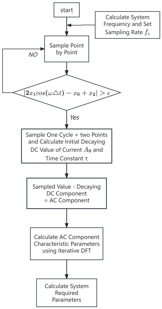
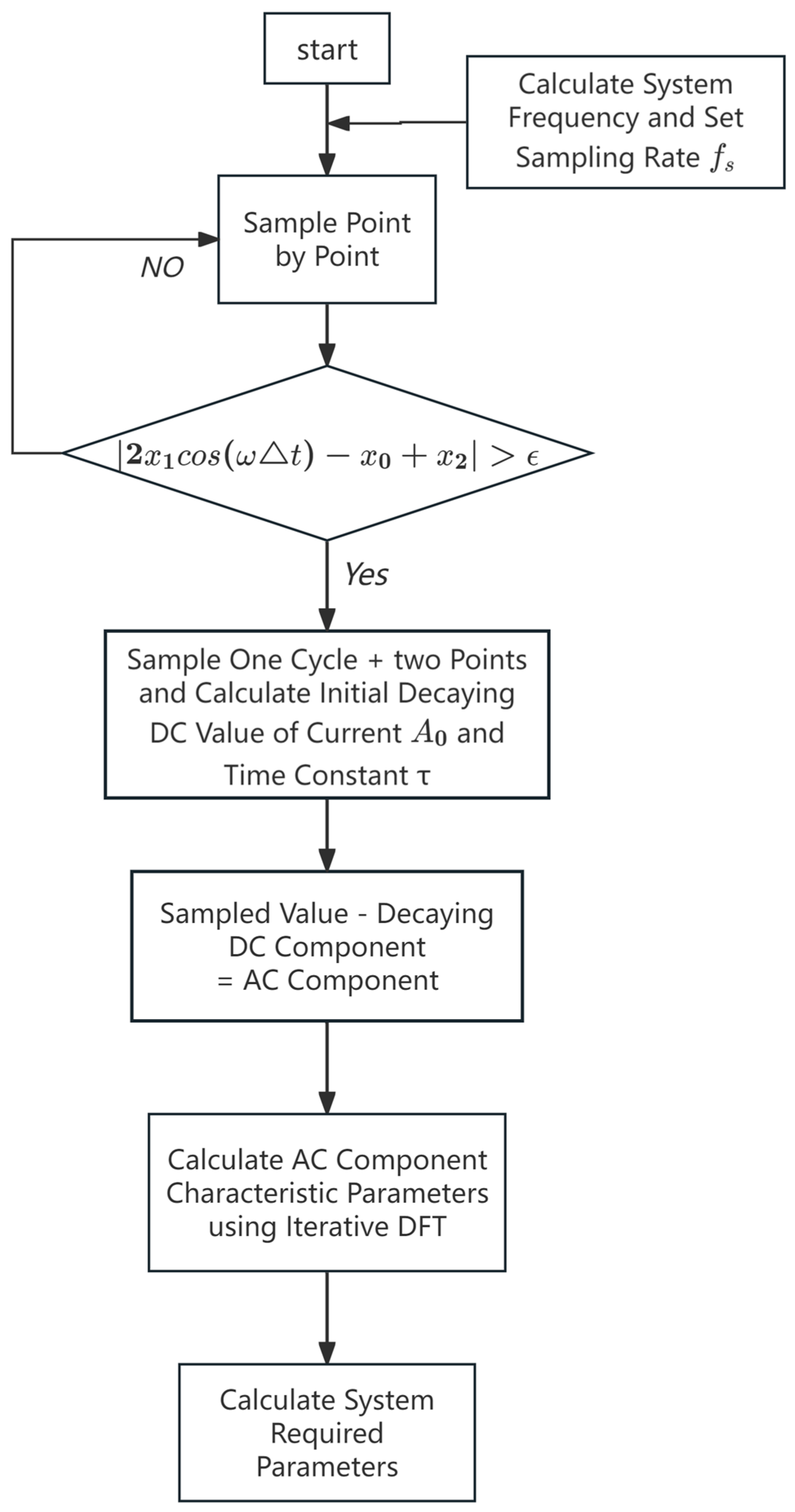
Figure 1 shows the flowchart of the fault detection method proposed.
Figure 1.
Flowchart of fault detection method.
4. Performance Evaluation
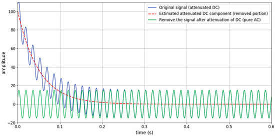
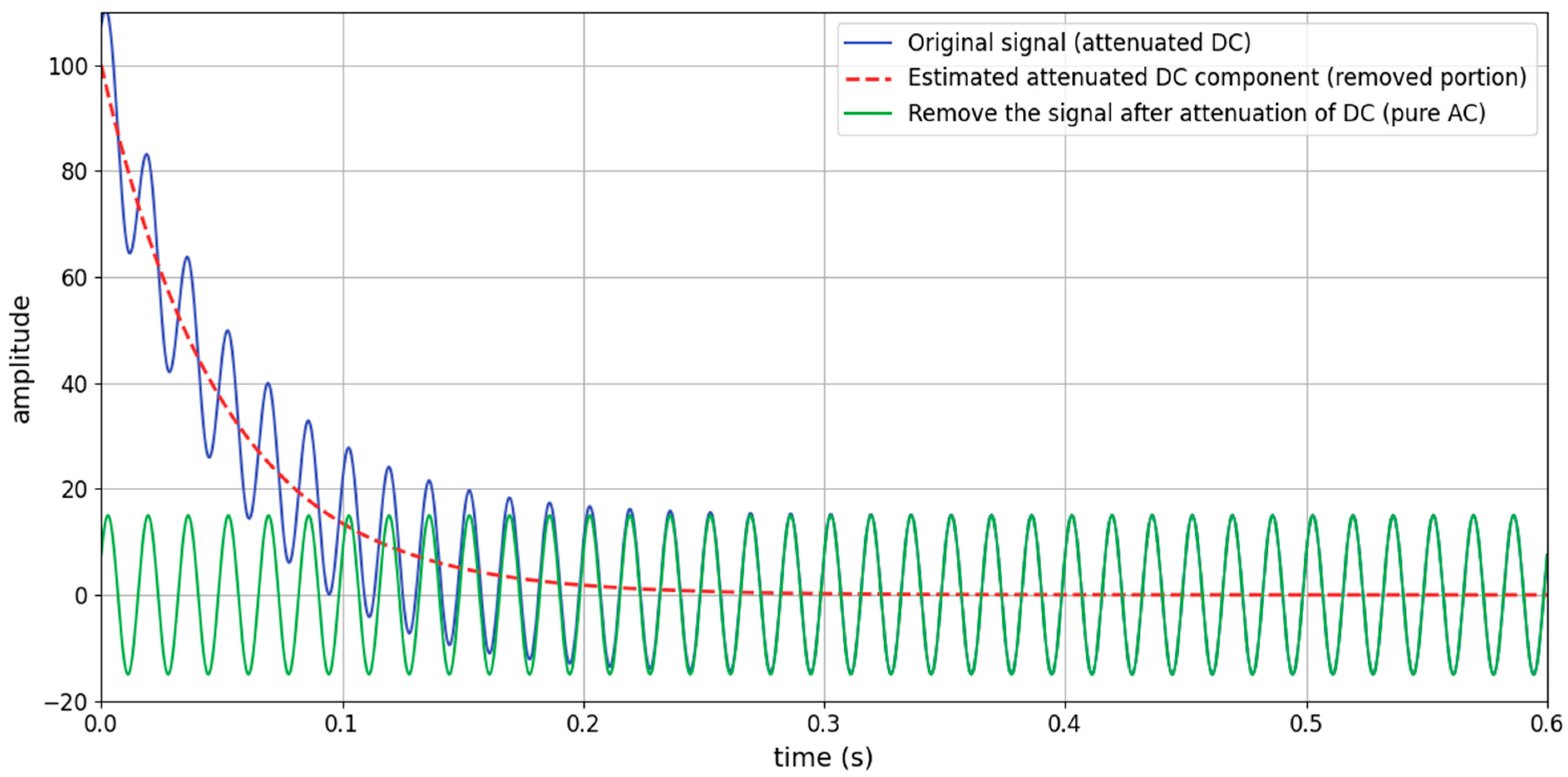
We conducted direct frequency calculations for various signal waveforms and compared them with the frequency calculation method presented in this paper. The comparison sample waveforms are illustrated in Table 1. A pure AC waveform is provided to simulate the system’s normal operating state. Then, a DC attenuation component is introduced at any given time point, with its parameters set to typical values. The complete calculation and comparison results are presented in Figure 2, demonstrating the superiority of this method.
Table 1.
Frequency estimation error table.
Figure 2.
Comparison of DC attenuation before and after removal.
5. Conclusions
Given that fault currents frequently inflict severe damage on power systems, rapid fault identification, accurate calculation of fault voltage and current values, and precise determination of system parameters have become critical challenges in modern protection schemes. After evaluating accuracy, timeliness, and computational complexity, the authors propose a hardware-integrated method for real-time parameter computation. This approach encompasses calculating the true system frequency, activating the fault detection mode, computing and filtering DC attenuation components, and performing iterative DFT for both fundamental and harmonic components. The experimental results demonstrate that the workflow can determine the system frequency within two cycles under normal operation and compute precise AC fault current parameters within one cycle plus two additional sampling points following fault occurrence.
The increasing integration of renewable energy generation and AC/DC conversion equipment in future power systems necessitates faster response times from protection devices. This heightens the challenge of reducing fault detection latency and optimizing parameter calculations. To more effectively pinpoint fault occurrence and enable practical circuit implementation, the moving-window time–frequency analysis method emerges as a promising research direction. Moreover, the widespread deployment of synchronous phasor measurement units in smart grids provides real-time system parameters and status data. Future efforts should focus on combining these real-time monitoring capabilities with operational data from smart grid measurement units to establish a robust foundation for rapid and reliable fault detection.
Author Contributions
Methodology, Z.L.; Conceptualization, K.L.; writing—original draft preparation, Q.X. All authors have read and agreed to the published version of the manuscript.
Funding
The research content and results described in this paper were supported by research funding from the Guangdong Provincial Science and Technology Plan Project, grant number 2024A0505050047.
Institutional Review Board Statement
Not applicable.
Informed Consent Statement
Not applicable.
Data Availability Statement
The data in this report pertains to the project’s progress and will not be made public for the time being.
Conflicts of Interest
The author declares no conflict of interest.
References
- Zhao, Y.S. A new algorithm for discrete Fourier algorithm. Sci. Technol. Inf. 2012, 388+421. (In Chinese) [Google Scholar] [CrossRef]
- Zhang, Y.Z. Optimal Recursive Fourier Transform Algorithm. J. Signal Process. 1987, 3, 177–185. (In Chinese) [Google Scholar]
- Liao, Z.Y. Digital filter for filtering out the decaying DC component in the Fourier algorithm. Power Syst. Prot. Control 1992, 1992, 21–25. (In Chinese) [Google Scholar]
- Zheng, X.H. Precise full-cycle Fourier algorithm for filtering attenuated DC components. Zhejiang Electr. Power 1998, 46–48, 57. (In Chinese) [Google Scholar] [CrossRef]
- Miñambres Argüelles, J.F.; Zorroza Arrieta, M.A.; Lázaro Domínguez, J.; Larrea Jaurrieta, B.; Sánchez Benito, M. A new method for decaying DC offset removal for digital protective relays. Electr. Power Syst. Res. 2006, 76, 194–199. [Google Scholar] [CrossRef] [Scilit]
- Yu, Y.L.; Xu, Y.H.; Liu, X.B. Study of harmonic current detection based on sliding-window iterative algorithm of DFT. Power Syst. Prot. Control 2011, 39, 78–82+90. (In Chinese) [Google Scholar]
- Thorp, J.S.; Phadke, A.G.; Adamiak, M.G. A new measurement technique for tracking voltage phasor, system frequency, and rate of change of frequency. IEEE Trans. Power Appar. Syst. 1983, PAS-102, 1020–1038. [Google Scholar] [CrossRef] [Scilit]

Disclaimer/Publisher’s Note: The statements, opinions and data contained in all publications are solely those of the individual author(s) and contributor(s) and not of MDPI and/or the editor(s). MDPI and/or the editor(s) disclaim responsibility for any injury to people or property resulting from any ideas, methods, instructions or products referred to in the content. |
© 2026 by the authors. Licensee MDPI, Basel, Switzerland. This article is an open access article distributed under the terms and conditions of the Creative Commons Attribution (CC BY) license.