


Abstract
The increasing integration of photovoltaic (PV) systems and nonlinear loads intensifies harmonic distortion and reactive power imbalance in modern power networks. Conventional shunt active power filters (SAPFs) often employ control strategies that perform poorly under uncertain and dynamic grid conditions. This paper develops a hybrid sliding mode control with disturbance observer (SMC+DOB) technique for a PV-integrated SAPF to achieve effective harmonic mitigation, reactive power compensation, and enhanced system robustness. The study models the PV-SAPF system in MATLAB/Simulink (R2025b), where the SMC ensures robust current tracking, while the DOB estimates and suppresses unknown disturbances in real-time. The controller’s performance is evaluated under varying nonlinear and reactive load conditions, as per IEEE 519-2014 standards. Simulation results show that the proposed SMC+DOB scheme reduces total harmonic distortion (THD) by 96.7%—from 31.45% to 1.05%—while maintaining DC-link voltage stability and unity power factor. The integrated control architecture enhances the dynamic performance of SAPF, providing superior harmonic suppression, fast transient recovery, and improved grid stability for PV-connected systems.
1. Introduction
The urgent global shift toward sustainable energy drives a rapid increase in grid-tied photovoltaic (PV) systems. However, integrating these systems with conventional grids via power electronic converters, coupled with the proliferation of nonlinear loads, introduces significant power quality challenges [1,2]. These issues include harmonic current injection and inadequate reactive power management, which can lead to equipment malfunctions, increased losses, and voltage instability [3].
Shunt active power filters (SAPFs) address these current-based problems by dynamically injecting compensating currents to ensure a sinusoidal grid current [4,5]. Yet, conventional control strategies, such as proportional-integral and hysteresis control, often perform poorly under dynamic grid conditions, including voltage sags and frequency deviations [6,7]. This limitation highlights the need for robust and adaptive control techniques.
In PV-integrated systems, the intermittency of renewable energy sources and the nonlinear loads jointly exacerbate power quality degradation [8]. To comply with standards like IEEE Std 519, researchers have developed SAPF-PV hybrid systems that simultaneously suppress harmonics and provide reactive power support [9]. Properly engineered SAPF-PV architectures demonstrably improve harmonic distortion indices, maintain voltage stability, and sustain high energy conversion efficiency across diverse operating conditions.
Extensive research has produced several effective control strategies for SAPF applications in PV systems. The Instantaneous Power Theory with Hysteresis Control, based on the p–q theory, effectively reduces total harmonic distortion (THD) in hybrid PV–micro-hydro systems; however, it suffers from variable switching frequencies [9]. Sliding mode control (SMC), derived from variable structure systems (VSS) theory, offers strong robustness and reduced dependence on accurate system models [10]. By enforcing system states onto a sliding surface, SMC simplifies dynamics and enhances stability, making it effective for PV-integrated SAPFs, especially during islanding and grid disturbances [11]. However, achieving precise harmonic compensation under abrupt grid variations remains challenging, requiring improved disturbance estimation.
SAPF technologies have advanced from basic harmonic compensators to multifunctional power conditioners [1,2]. While conventional PI and hysteresis controls offer simplicity, they lack robustness; adaptive, neural, and fuzzy methods enhance performance but increase computational demand [12]. SMC provides a robust alternative, but its chattering requires mitigation. Recent studies show PV inverters performing dual roles in harmonic and reactive power compensation, with advanced controllers like passivity-based control (PBC) and SMC delivering IEEE-compliant THD reduction and superior dynamic performance in multilevel inverter systems [13,14]. Hybrid and intelligent control schemes, notably those utilizing disturbance observer (DOB), enhance the robustness of SAPFs through real-time disturbance estimation and compensation [15]. Advanced observers, such as extended state observers (ESOs), improve disturbance rejection [16]. In contrast, hybrid SMC methods combining fuzzy logic or neural networks reduce chattering and enhance adaptability, albeit at the cost of higher computational demands [9,17].
Research Methodology and Performance Evaluation
Despite significant advancements, applying combined DOB–SMC schemes to PV-integrated SAPFs and improving resilience under severe grid disturbances remain open challenges. This study proposes a hybrid control architecture that integrates SMC for robust current tracking with a DOB for real-time disturbance estimation, addressing these issues. The integrated controller enhances harmonic suppression, reactive power support, and fault ride-through capability. A detailed PV-SAPF model captures system nonlinearities, while the controller employs optimized sliding surfaces, adaptive disturbance estimation, and coordinated SMC–DOB interaction. Comprehensive MATLAB/Simulink simulations under varied conditions benchmark the proposed strategy against conventional methods. Key metrics—THD reduction, transient response, and steady-state precision—demonstrate superior power quality, dynamic stability, and control robustness. The results validate the effectiveness of the hybrid SMC–DOB controller in achieving reliable harmonic mitigation and enhanced grid resilience for PV-based active power filtering applications.
2. System Modeling and Configuration
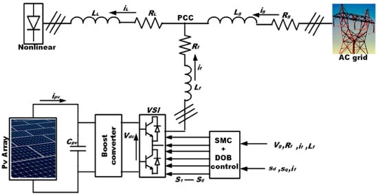
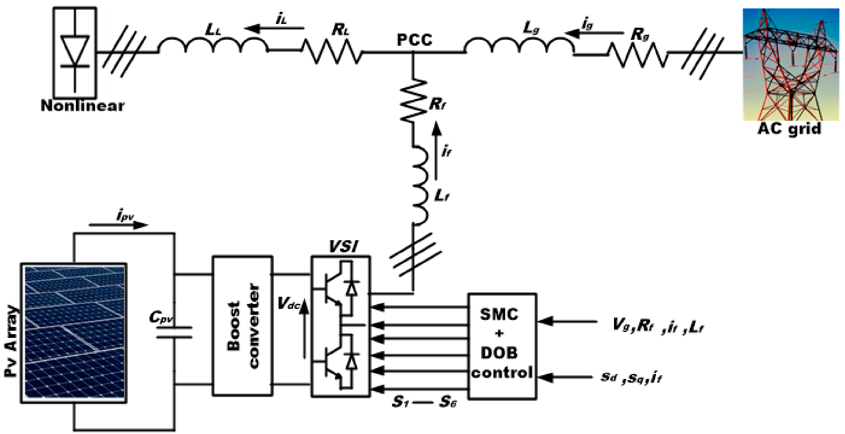
The system under consideration, depicted in Figure 1, consists of a PV array connected to a DC-DC converter, a three-phase voltage source inverter (VSI) acting as the SAPFs, a nonlinear load, and the utility grid. The proposed system integrates a grid-connected PV array with a SAPFs for power quality enhancement at the point of common coupling (PCC). A boost converter regulates the DC link voltage, supplying a VSI that injects compensating currents through an -filter. The control architecture utilizes an SMC and a DOB to ensure robust tracking of reference currents derived from the instantaneous power (p–q) theory. This configuration effectively mitigates harmonic distortion and provides reactive power support, improving grid current quality and maintaining system stability under varying load and grid conditions, including voltage sags, swells, and frequency variations [18]. The configuration is similar to that presented in [16,19], where the circuit dynamics are analyzed by considering it as a balanced three-phase system, as described below.
Figure 1.
Proposed system configuration of a grid-integrated PV system.
2.1. System Overview
As illustrated in Figure 1, the proposed system integrates a grid-tied PV array with a SAPF to enhance power quality. The system connects to a balanced three-phase voltage source that supplies phase voltages, , and delivers currents ,. This grid establishes the PCC, which feeds the nonlinear load and interfaces with the SAPF. A nonlinear load, represented by a resistive–inductive element (), supplied through a diode bridge rectifier, draws distorted currents that inject significant voltage and current harmonics into the system. These distortions necessitate active compensation. The PV array connects to the DC side of the inverter and functions as the primary renewable energy source. A DC-link capacitor () regulates the PV output by stabilizing the DC bus voltage and providing transient energy buffering, thereby ensuring continuous support to the converter under dynamic operating conditions. This configuration offers energy buffering and maintains continuous support to the VSI, even under transient and dynamic operating conditions. The SAPFs employs a three-phase VSI that interfaces with the PCC through a filter inductor, . The VSI generates compensating currents, , , which counteract the harmonic and reactive components introduced by the nonlinear load. By operating under a current control strategy, the VSI injects precisely regulated compensating currents into the grid, thereby mitigating distortions and enhancing overall power quality. The inverter switching operates under an SMC strategy, which ensures robust performance despite parameter uncertainties, nonlinear dynamics, and external disturbances. The SMC achieves rapid current tracking and effective harmonic mitigation in real time by forcing system trajectories to converge toward a predefined sliding surface. To further enhance resilience, the control loop integrates a DOB that continuously estimates and compensates for grid disturbances, model inaccuracies, and load variations. This dynamic compensation significantly strengthens disturbance rejection and improves transient response.
Additionally, the control algorithm incorporates reactive power compensation, allowing for adaptive voltage support at the PCC during fluctuating grid and load conditions. This function ensures compliance with modern grid codes while maintaining voltage stability and continuity of supply. The SMC, DOB, and reactive power compensation create a robust control framework that delivers harmonic suppression, reactive power support, and fault ride-through capability, thereby significantly advancing SAPF-based control for grid-integrated PV systems.
2.2. Grid and Load Model
The study models the three-phase grid, as shown in Figure 1, using its Thevenin equivalent representation. The voltage at the PCC for each phase can be described by (1), where is the grid voltage at PCC, vg is the peak voltage of the grid, and is the angular frequency, and Rs are the grid-side inductance and resistance, and is the grid current. The total load current () is the sum of the grid current () and the filter current (), as presented in (2).
The vector representation of grid voltage at PCC, grid current, load current, and the filter current (3-phase) is expressed in (3).
KCL is applied at the PCC to derive the fundamental system relationship in vector form, as expressed in (4).
2.3. SAPF and Inverter Dynamics
To capture the behavior of the SAPF, we model the inverter output current dynamics per phase in (5):
We generalize (5) for all three phases using vector notation in (6).
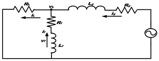
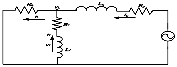
Figure 2 presents the one-line diagram of the proposed SAPFs model. The SAPFs is a three-phase VSI connected to the grid through a filter inductor, . The voltage dynamics across the grid and SAPFs are represented, respectively, in Equations (7) and (8):
Figure 2.
Active filter block diagram designations [19].
Combining (7) and (8), we obtain a dynamic expression for the source current,
To ensure harmonic compensation, we define the ideal relation between fundamental and harmonic components of the load and SAPFs currents in (10):
where is the fundamental load current, is the harmonic component of the load current, while is the filter current. When the filter operates effectively, the grid should supply only the fundamental elements of the load current. At the same time, the SAPFs provides the harmonic components required by the nonlinear load, as mathematically expressed in (10). Correspondingly, one can interpret the right-hand side of (10) as a filter current difference term that the controller must address in the upcoming control period. Hence, the controller can also express Equation (10) as shown in (11).
Finally, we combine system parameters to obtain a simplified model that forms the basis for control design given in (12).
2.4. Inverter Switching and DC-Link Dynamics
We represent the inverter voltage per phase as a product of switching state and DC-link voltage: Where is the inverter’s output voltage for phase a’, which is regulated by the switching state of the VSI. If we define a switching function, , the inverter voltage can be expressed in terms of the DC-link voltage .
We then model the dynamics of the DC-link capacitor using the net current supplied by the PV array and consumed by the inverter shown in (14), where , is the current from the PV array and , is the DC-link capacitance.
2.5. dq Transformation and SMC
We transform the system into a synchronous rotating reference frame to design the current controller. We express the dq-frame current dynamics as (15):
2.6. Proposed Adaptive Control Strategy
The control objective is to ensure that the grid current, ig, remains sinusoidal and in phase with the grid voltage, regardless of the load current, iL. To achieve this, the SAPF injects a filter current and cancels the harmonic and reactive components of the load current. As a result, the reference filter current, , is derived accordingly. We employ an SMC for its fast dynamic response and robustness. The SMC design process typically includes defining the sliding surface (SS) function, selecting suitable sliding coefficients, determining the control input, applying chattering mitigation techniques, and incorporating appropriate modulation strategies. The design process begins by defining the current tracking error. We define the current tracking error for the SMC in (16):
Introduce the SS to drive this error to zero:
Take the derivative of the SS and substitute the filter dynamics:
Define the dq-axis SS for control implementation:
We then derive the SMC-based control laws for the inverter voltage in the dq-frame:
2.7. DOB Integration
A DOB is incorporated into the study to handle grid anomalies and parameter uncertainties. We incorporate a DOB that estimates external system perturbations to reduce chattering. We redefine the current dynamics to include an unknown disturbance term. Let represent the lumped disturbance, including grid voltage distortions and parameter variations. The study reformulates the system dynamics as:
To estimate the system disturbance, , we design a DOB based on a sliding mode structure. The observer provides a real-time estimate of the external or model uncertainties affecting system performance. A straightforward implementation involves designing a Luenberger-style observer, as given in (23), which strikes a balance between simplicity and practical disturbance estimation. Where is the observer gain, the estimated disturbance is then used to modify the control law, providing proactive compensation:
We define as the observer gain and uses the estimated disturbance to enhance the robustness of the control system. Accordingly, (24) modifies the SMC law by incorporating the estimated disturbance, which proactively compensates for system uncertainties and reduces switching ripple:
2.8. Reactive Power Support Control
The controller achieves reactive power compensation by adjusting the phase of the reference current. The controller incorporates a reactive power support logic that dynamically regulates the inverter’s contribution to reactive power. Specifically, the reference source current magnitude is determined based on the active power demand of the load and the instantaneous power supplied by the PV array. Meanwhile, the reactive component of the current can be independently specified, allowing the system to support grid voltage regulation and power factor correction in a flexible manner.
The phase angle φ is adjusted to inject or absorb reactive power based on the PCC voltage deviation from its nominal value (26), providing voltage support. is the proportional gain.
3. Simulation Results
This section presents detailed simulation results validating the proposed SMC+DOB control strategy for the SAPF. The system is evaluated under various operating conditions to demonstrate the controller’s effectiveness. Simulations are conducted in MATLAB/Simulink with a 10 kHz sampling frequency over a 1 s period to capture both transient and steady-state responses. The test setup includes a severely distorted nonlinear load with fundamental, 3rd, 5th, and 7th harmonic components, producing an initial THD of about 30%. The SAPF activates at t = 0.1 s, and a 50% load step change is applied at t = 0.5 s to assess dynamic performance, while the controller regulates the DC-link voltage at 600 V. The results confirm the effectiveness of the SMC+DOB controller in stabilizing DC-link voltage, mitigating harmonics, enhancing power quality, and compensating for reactive power. Time-domain waveforms, frequency-domain spectra, and quantitative performance metrics illustrate its superior compensation capability and robustness under dynamic conditions. Table 1 lists the system and control parameters used in the study.
Table 1.
System and Control Parameters for Simulation.
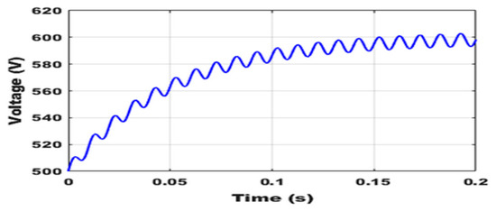
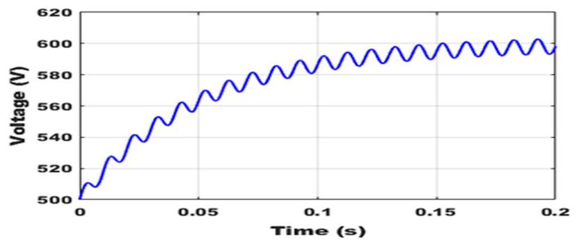
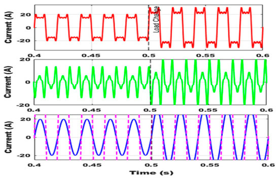
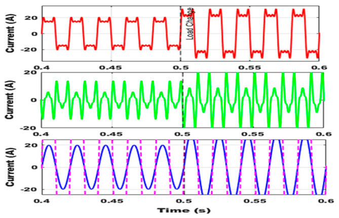
Figure 3 plots the transient and steady-state performance of the DC-link capacitor voltage. The controller rapidly drives the voltage from its initial condition to the reference value of 600 V, settling with minimal overshoot. The waveform maintains this setpoint with only a small, expected 100 Hz ripple, confirming the controller’s robustness in regulating the DC-link voltage against disturbances and its effectiveness in providing a stable energy source for the inverter. Figure 4 illustrates the dynamic current compensation performance of the SAPF under a step change in load at t = 0.5 s. The top panel shows the highly distorted and non-sinusoidal current drawn by the nonlinear load. The middle panel displays the compensating current generated by the SAPF, which actively injects the required harmonic components to compensate for the harmonic distortion. The bottom panel demonstrates that the grid current remains sinusoidal and in phase with the grid voltage both before and after the load change. This result verifies that the proposed controller effectively forces the grid current to track its sinusoidal reference, even during transient load conditions.
Figure 3.
DC-link voltage rising from 500 V to ~600 V with steady-state ripple (0–0.2 s).
Figure 4.
Waveforms of three-phase load, SAPFs compensating, and source currents before and after a load change.
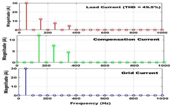
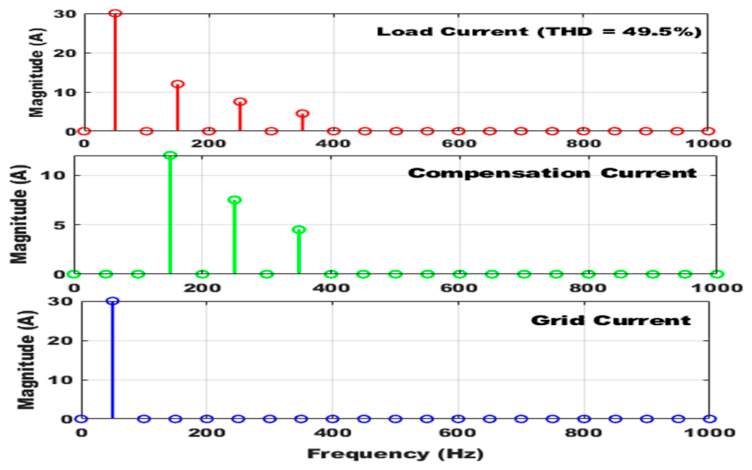
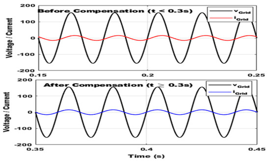
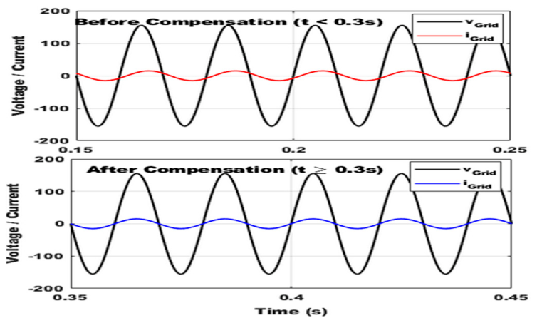
A Fast Fourier Transform (FFT) analysis was employed to evaluate the harmonic suppression capability of the proposed system under steady-state conditions. Figure 5 illustrates the frequency spectra of the load, compensation, and grid currents. The load current exhibits a high THD of 23.85%, dominated by the 3rd, 5th, and 7th harmonics. The SAPFs injects compensating currents at these frequencies, resulting in a grid current THD of only 0.84%, confirming the controller’s strong harmonic elimination performance. Figure 6 demonstrates reactive power compensation. Before compensation (t < 0.3 s), the grid current lags the voltage, indicating reactive power consumption; after compensation (t ≥ 0.3 s), the grid current aligns perfectly with the voltage, achieving a unity power factor by locally supplying the required reactive power. The FFT results further show that the SMC+DOB-controlled SAPF reduces THD from 31.45% in the load current to 1.05% in the grid current (Table 2). All harmonic components remain within IEEE 519-2014 limits, with the highest (3rd) at 0.60% of the fundamental. The system achieves 96.7% compensation efficiency and maintains excellent dynamic response during a 50% load step change at t = 0.5 s, confirming the controller’s robustness and effectiveness in preserving power quality under varying conditions.
Figure 5.
Harmonic spectrum showing distorted load current, SAPFs compensation current, and the resulting improved grid current.
Figure 6.
Reactive power compensation showing lagging grid current before and in-phase current after, achieving unity power factor.
Table 2.
The SAPFs Performance Results.
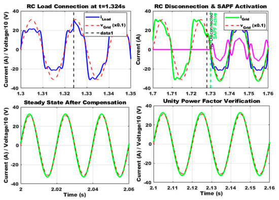
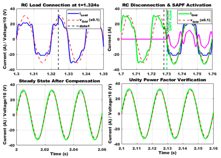
The second experimental scenario assesses the proposed SMC+DOB-controlled SAPFs under combined nonlinear and reactive load conditions. Figure 7 shows that the system maintains excellent dynamic response, harmonic suppression, and reactive power compensation during load transitions. The test begins with a standalone nonlinear load at the PCC, producing a THD of 4.9% and a near-unity power factor (0.991). At t = 1.324 s, a high-capacitive RC load is added in parallel, forming a combined nonlinear–reactive load that reduces the THD to 4.2% while improving the power factor to approximately 0.995, indicating stronger fundamental current dominance. After both loads operate concurrently, the system disconnects the RC load at t = 1.728 s, and the SAPFs is activated at t = 1.730 s, reaching full compensation within milliseconds. The oscilloscope highlights three key waveforms: the composite load current (blue), with nonlinear and capacitive characteristics; the inverter compensation current (magenta), aligned with the sinusoidal reference; and the compensated grid current (green), achieving a near-perfect sinusoid in phase with the voltage, confirming a unity power factor. The proposed control strategy enhances power quality by effectively mitigating dominant harmonics (3rd, 5th, and 7th) and providing complete reactive power compensation in compliance with IEEE 519-2014. The system achieves rapid response (<10 ms), stable operation during 40% load variations, and maintains a final grid current THD below 5% with a power factor above 0.99. These results demonstrate the robustness and suitability of the SMC+DOB-controlled SAPF for real-time industrial power conditioning applications that require reliable harmonic and reactive power compensation.
Figure 7.
Dynamic response of the SMC+DOB SAPFs under nonlinear RC load: disconnection, and activation, showing transition to steady-state compensation and unity power factor.
4. Conclusions
This study presents a hybrid control architecture that integrates SMC with a DOB to enhance harmonic suppression, reactive power compensation, and fault ride-through capability in PV-integrated power systems. The SMC ensures robust current tracking and rapid disturbance rejection, while the DOB continuously estimates and compensates for grid voltage distortion, parameter variations, and nonlinear load disturbances in real time. The integrated controller achieves superior harmonic mitigation, reducing THD from 31.45% to 1.05%, corresponding to a 96.7% improvement in power quality. Simulation results confirm stable DC-link regulation at 600 V, fast transient recovery under 50% load variations, and unity power factor operation for nonlinear and reactive loads. The hybrid SMC–DOB controller suppresses chattering, enhances dynamic stiffness, and complies fully with IEEE Std. 519–2014 harmonic limits. By combining robust control with adaptive disturbance estimation, the approach enables simultaneous renewable energy interfacing and advanced power conditioning within a single converter platform, offering a highly efficient and scalable solution for smart grids. Future work will implement the controller in real time using DSP and FPGA platforms to assess computational efficiency and hardware performance. Further research will utilize AI- and ML-based adaptive tuning to optimize control gains under dynamic grid conditions, and extend the framework with predictive control and model-based disturbance estimation to enhance compensation accuracy under severe distortion and intermittent renewable generation. Long-term HIL validation and field testing will verify the system’s scalability, reliability, and readiness for large-scale renewable and microgrid applications.
Author Contributions
J.O.U.: led the study design, investigation, methodology, software development, and original drafting. A.K.S.: supervised and administered the project, validated the results, and revised the manuscript. All authors have read and agreed to the published version of the manuscript.
Funding
This research received no external funding.
Institutional Review Board Statement
Not applicable.
Informed Consent Statement
Not applicable.
Data Availability Statement
The manuscript contains all relevant data.
Acknowledgments
We acknowledge the institutional support of the University of KwaZulu-Natal.
Conflicts of Interest
The authors declare no conflicts of interest.
Abbreviations
The following abbreviations are used in this manuscript:
| PV | Photovoltaic |
| SAPF | Shunt Active Power Filter |
| VSI | Voltage Source Inverter |
| PCC | Point of Common Coupling |
| THD | Total Harmonic Distortion |
| SMC | Sliding Mode Control |
| DOB | Disturbance Observer |
| ESO | Extended State Observer |
| PBC | Passivity-Based Control |
| VSS | Variable Structure Systems |
| PI | Proportional–Integral |
| FFT | Fast Fourier Transform |
| DC | Direct Current |
| AC | Alternating Current |
| dq | Direct–Quadrature Reference Frame |
| KCL | Kirchhoff’s Current Law |
| RC | Resistive–Capacitive |
| RL | Resistive–Inductive |
| HIL | Hardware-in-the-Loop |
| DSP | Digital Signal Processor |
| FPGA | Field-Programmable Gate Array |
| AI | Artificial Intelligence |
| ML | Machine Learning |
References
- Akagi, H. A shunt active filter based on voltage detection for harmonic termination of a radial power distribution line. IEEE Trans. Ind. Appl. 1999, 35, 638–645. [Google Scholar] [CrossRef] [Scilit]
- Vadirajacharya, K.; Agarwal, P.; Gupta, H.O. A simple control strategy for unified power quality conditioner using current source inverter. In 8th International Power Engineering Conference, IPEC 2007; IEEE: New York, NY, USA, 2007; pp. 1219–1223. [Google Scholar]
- Gong, J.; Li, D.; Wang, T.; Pan, W.; Ding, X. A comprehensive review of improving power quality using active power filters. Electr. Power Syst. Res. 2021, 199, 107389. [Google Scholar] [CrossRef] [Scilit]
- Zaro, F. Shunt Active Power Filter for Power Quality Improvement of Renewable Energy Systems: A Case Study. WSEAS Trans. Power Syst. 2023, 18, 241–247. [Google Scholar] [CrossRef] [Scilit]
- Popescu, M.; Bitoleanu, A.; Suru, C.V.; Linca, M.; Alboteanu, L. Shunt Active Power Filters in Three-Phase, Three-Wire Systems: A Topical Review. Energies 2024, 17, 2867. [Google Scholar] [CrossRef] [Scilit]
- Artemenko, M.; Chopyk, V.; Polishchuk, S.; Mykhalskyi, V.; Shapoval, I. Integral Power Theory and Active Filtering Using the α-β Reference Frame. IEEE Access 2024, 12, 60004–60014. [Google Scholar] [CrossRef] [Scilit]
- Karania, N.; Alali, M.A.; Di Gennaro, S.; Barbot, J.P. Advanced High Switching-Frequency Cascaded H-Bridge Multilevel Inverter Based Shunt Active Filter for PV Generation: A Case Study. IEEE Open J. Ind. Appl. 2025, 6, 262–280. [Google Scholar] [CrossRef] [Scilit]
- Guerrero-Rodríguez, N.F.; Batista-Jorge, R.O.; Ramírez-Rivera, F.A.; Ferreira, J.; Mercado-Ravelo, R.; Manilla, A. Harmonic Distortion Study of a Photovoltaic Generator in a Microgrid under Disturbances. Energies 2024, 17, 2031. [Google Scholar] [CrossRef] [Scilit]
- Boopathi, R.; Indragandhi, V. Experimental Investigations on Photovoltaic Interface Neutral Point Clamped Multilevel Inverter-Based Shunt Active Power Filter to Enhance Grid Power Quality. IEEE Access 2024, 12, 74482–74498. [Google Scholar] [CrossRef] [Scilit]
- Komurcugil, H.; Biricik, S.; Bayhan, S.; Zhang, Z. Sliding Mode Control: Overview of Its Applications in Power Converters. IEEE Ind. Electron. Mag. 2021, 15, 40–49. [Google Scholar] [CrossRef] [Scilit]
- Kihal, A.; Talbi, B.; Krama, A.; Laib, A.; Sahli, A. A Multi-Functional Grid-Tied PV system using a Split Source Inverter with Energy management and Power Quality Improvement Features. IEEE Access 2025, 13, 29789–29800. [Google Scholar] [CrossRef] [Scilit]
- Uwagboe, J.O.; Saha, A.K. A Comprehensive Review of Multilevel Inverter Topologies and Control Strategies for Grid-Connected Photovoltaic Battery Energy Storage Systems Integrating Active Power Filter; Institute of Electrical and Electronics Engineers Inc.: New York, NY, USA, 2025. [Google Scholar] [CrossRef] [Scilit]
- Latran, M.B.; Teke, A. Investigation of multilevel multifunctional grid connected inverter topologies and control strategies used in photovoltaic systems. Renew. Sustain. Energy Rev. 2015, 42, 361–376. [Google Scholar] [CrossRef] [Scilit]
- Babaie, M.; Sharifzadeh, M.; Kanaan, H.Y.; Al-Haddad, K. Switching-Based Optimized Sliding-Mode Control for Capacitor Self-Voltage Balancing Operation of Seven-Level PUC Inverter. IEEE Trans. Ind. Electron. 2021, 68, 3044–3057. [Google Scholar] [CrossRef] [Scilit]
- Bagherwal, S.; Mahapatra, S. Enhanced Stability and Control of Solar Powered EV Charging Stations using Disturbance Observer-based Adaptive Sliding Mode Control for DC Voltage Stabilization. IEEE Access 2024, 12, 183293–183311. [Google Scholar] [CrossRef] [Scilit]
- Flota-Bañuelos, M.; Miranda-Vidales, H.; Cruz, B.; Aviles-Viñas, J.; Ricalde, L.; Medina, J. Sliding Mode Control and Immersion & Invariance Observer for Grid-Tied Inverters in Photovoltaic Applications: Continuous Operation for Power Quality Enhancement. Energies 2024, 17, 6235. [Google Scholar] [CrossRef] [Scilit]
- Jouybary, H.S.; Khaburi, D.A.; El Hajjaji, A.; Mabwe, A.M. Optimal Sliding Mode Control of Modular Multilevel Converters Considering Control Input Constraints. Energies 2025, 18, 2757. [Google Scholar] [CrossRef] [Scilit]
- Kiruthiga, B.; Karthick, R.; Manju, I.; Kondreddi, K. Optimizing Harmonic Mitigation for Smooth Integration of Renewable Energy: A Novel Approach Using Atomic Orbital Search and Feedback Artificial Tree Control. Prot. Control Mod. Power Syst. 2024, 9, 160–176. [Google Scholar] [CrossRef] [Scilit]
- Flota-Bañuelos, M.; Miranda-Vidales, H.; Fernández, B.; Ricalde, L.J.; Basam, A.; Medina, J. Harmonic Compensation via Grid-Tied Three-Phase Inverter with Variable Structure I&I Observer-Based Control Scheme. Energies 2022, 15, 6419. [Google Scholar] [CrossRef] [Scilit]

Disclaimer/Publisher’s Note: The statements, opinions and data contained in all publications are solely those of the individual author(s) and contributor(s) and not of MDPI and/or the editor(s). MDPI and/or the editor(s) disclaim responsibility for any injury to people or property resulting from any ideas, methods, instructions or products referred to in the content. |
© 2026 by the authors. Licensee MDPI, Basel, Switzerland. This article is an open access article distributed under the terms and conditions of the Creative Commons Attribution (CC BY) license.