


Abstract
The design of Hybrid-Electric Regional (HER) aircraft represents a great challenge due to the systems’ complexity and their level of integration and results in a great expense of resources. To overcome these issues, the Open Digital Environment for Hybrid-Electric Regional Architecture (ODE4HERA) project is developing an Open Digital Platform (ODP) to accelerate the design process. The platform is validated using a pilot case which focuses on powertrain systems and covers the entire development process, from requirements definition to Virtual Integrated Verification and Validation (IV&V). At first, the design is performed using state-of-the-art tools; then it is repeated using preliminary ODP modules to evaluate the achieved benefits.
1. Introduction
As aeronautical systems become more advanced, the complexity of the design process greatly increases making the development of competitive solutions more difficult and time/cost demanding. This is especially true for Hybrid-Electric Regional (HER) vehicles since their powertrains can handle over twice the number of parameters and many times more combinations than conventional configurations [1].
The Open Digital Environment for Hybrid-Electric Regional Architecture (ODE4HERA) project aims to accelerate the design process through the development of an Open Digital Platform (ODP) that combines Model Based System Engineering (MBSE), Multidisciplinary Design Analysis and Optimization (MDAO), Simulation Data Management (SDM), and Product Lifecycle Management (PLM) technologies, extending them with novel open interfaces and data transformation technologies. At the end of the project, the platform is expected to achieve a Technology Readiness Level (TRL) of 5 [1]. The approach of the ODP is different from other known frameworks, such as RCE or OpenMDAO.
The Remote Component Environment (RCE), developed by DLR, provides a peer-to-peer workflow execution framework widely used in aerospace projects such as AGILE and AGILE 4.0 [2]. Similarly, OpenMDAO is a NASA Python-based framework optimized for multidisciplinary design optimization [3]. Both tools excel at workflow execution; however, they operate as point-to-point integration platforms requiring manual tool interface definition and offer limited support for requirements traceability. The ODP from ODE4HERA distinguishes itself by adopting SysMLv2 as a vendor-neutral, semantically rich data model that enables automatic data transformation between heterogeneous tools with minimal user intervention, while simultaneously integrating MBSE with MDAO—a capability not provided by existing workflow integration frameworks [4,5,6,7].
This paper presents the activities carried out in the context of Work Package 4 aiming to validate the ODP through a pilot case, the so-called Application Case 1. This focuses on the powertrain of Ultra Efficient Regional Aircraft [8], shown in Figure 1.
Figure 1.
Application Case 1 design problem and scope [8].
The analyzed System of Interest (SoI) contains the following Aircraft Systems:
- Electrical Power Generation, consisting of two battery packs;
- Electrical Power Distribution, providing electrical power to propulsive and non-propulsive loads. The Smart Electric Power Management manages the electrical generation and load shedding/optimization in all flight conditions;
- Propulsive System, containing thermal engines and electric motors arranged in a parallel layout. They transmit the movement to the propeller through a gearbox.
2. Development Process
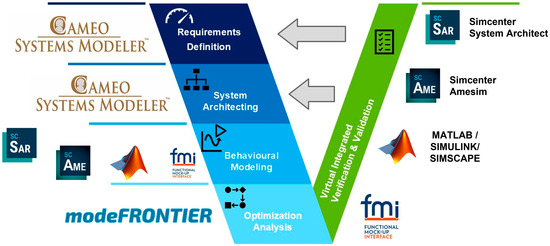
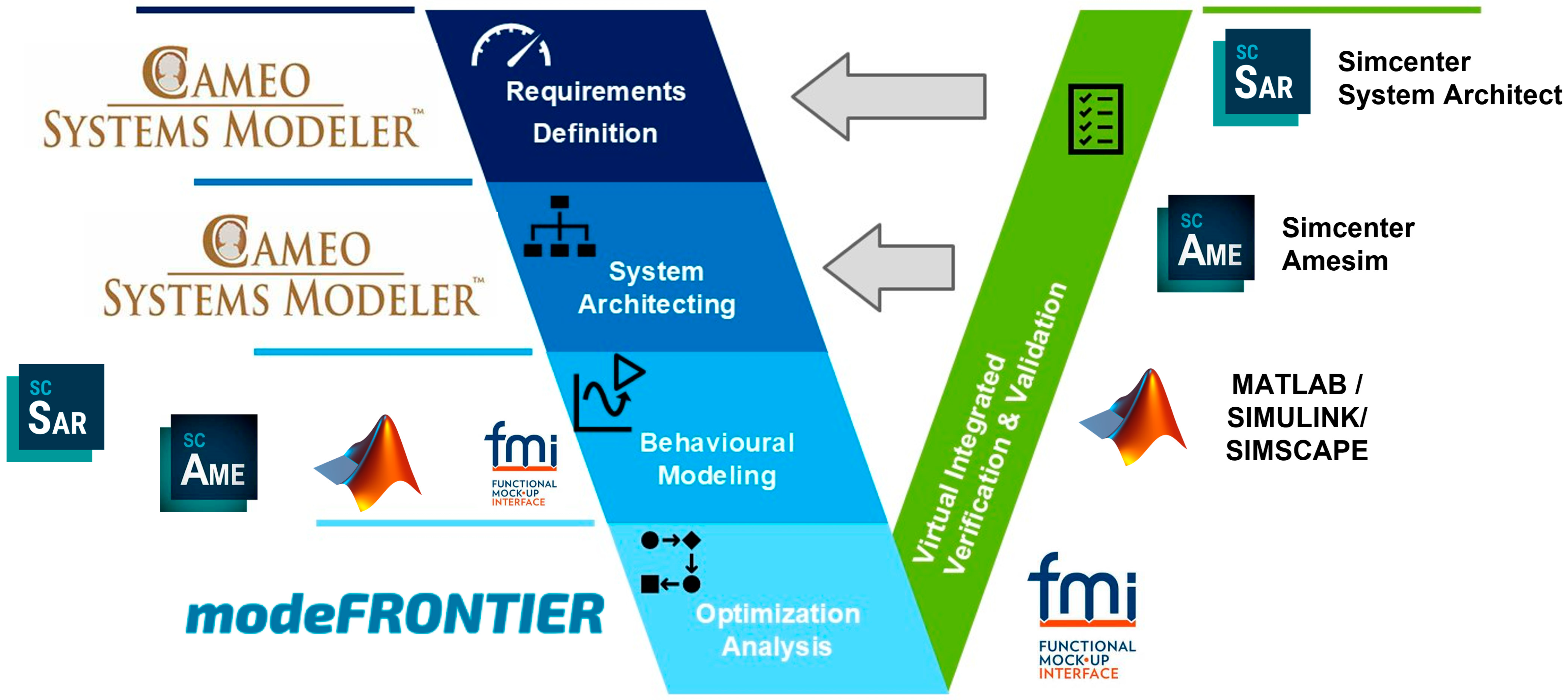
The design process followed in Application Case 1 is summarized in Figure 2 together with the adopted tools.
Figure 2.
Application Case 1 design process. The integrated verification and validation accelerate the development of the models, bringing the right side of the V closer to the left side.
2.1. Definition of Requirements and Functional Modeling
According to the MagicGrid approach [9], the starting point is the collection of Top Level Aircraft Requirements (TLARs) in Cameo Systems Modeler™ [10], an MBSE environment allowing generation, analysis and management of SysML-compliant models. TLARs represent what stakeholders expect from the SoI and define, among the others, the maximum payload or the design range demanded by the stakeholders. They are decomposed at lower levels following the process described in [9], that is articulated in:
- Operational Analysis which considers the SoI as a Black-Box to understand how it interacts with the environment. As a result, Vehicle Requirements are obtained to define how the entire vehicle will meet the TLARs (e.g., the Vehicle Requirement “the Aircraft shall generate the adequate thrust for its on-ground and in-flight maneuvers” fulfills the TLARs about the design mission profile).
- Functional Analysis, that considers the SoI as a White-Box to detail how it operates. As a result, Vehicle Requirements are decomposed into Aircraft Systems Requirements. For instance, the Vehicle Requirement presented earlier results in several specifications for the Aircraft Systems, such as “the Electrical Power Generation shall provide the requested amount of electric power to actuate the Propulsion System”.
At the end, starting from about 20 TLARs, near 60 Vehicle Requirements and 330 Aircraft Systems Requirements are obtained.
2.2. System Architecture
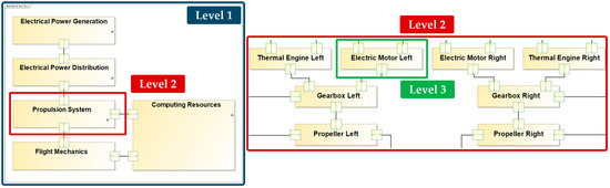
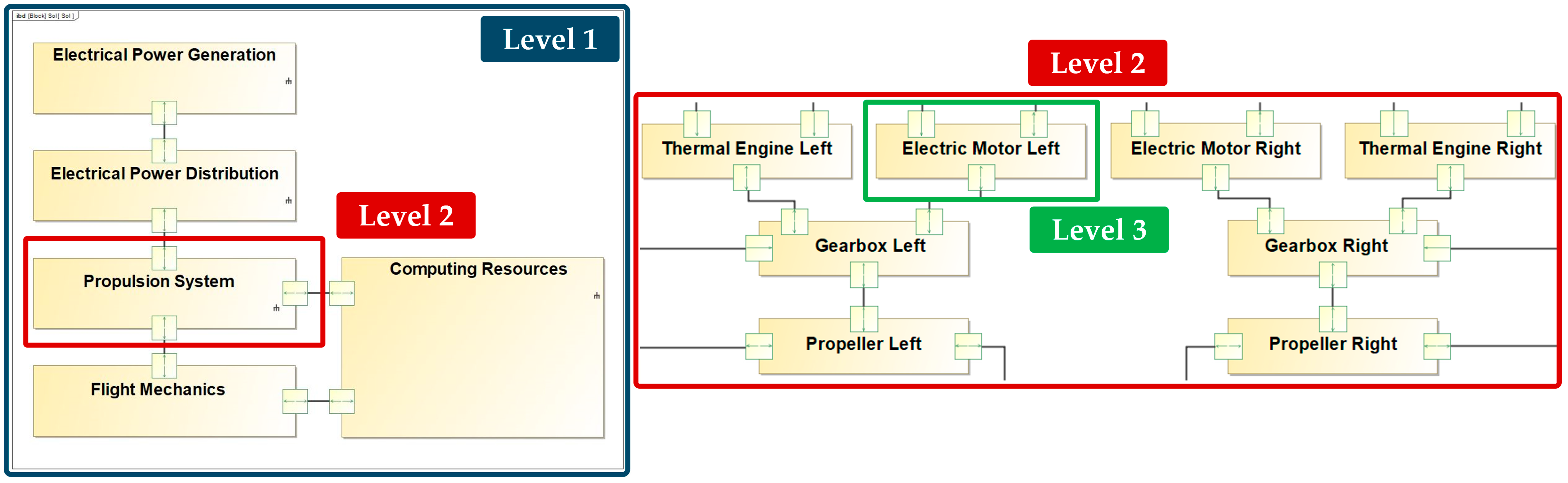
Figure 3 reports the System Architecture defined in Cameo Systems Modeler™ 19.0 through Internal Block Diagrams. The SoI is decomposed into multiple levels:
Figure 3.
System Architecture with three levels of granularity in Cameo Systems Modeler™.
- Level 1 corresponds to the vehicle and models the interfaces exchanged among the Aircraft Systems;
- Each Level 2 block represents a single Aircraft System (e.g., Propulsion System);
- Level 3 is associated with components. For example, Propulsion System includes electric motors, thermal engines, gearboxes, and propellers.
2.3. Behavioral Modeling
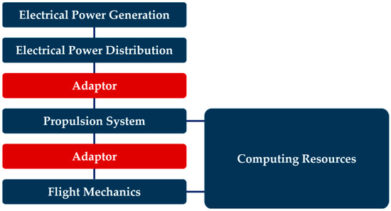
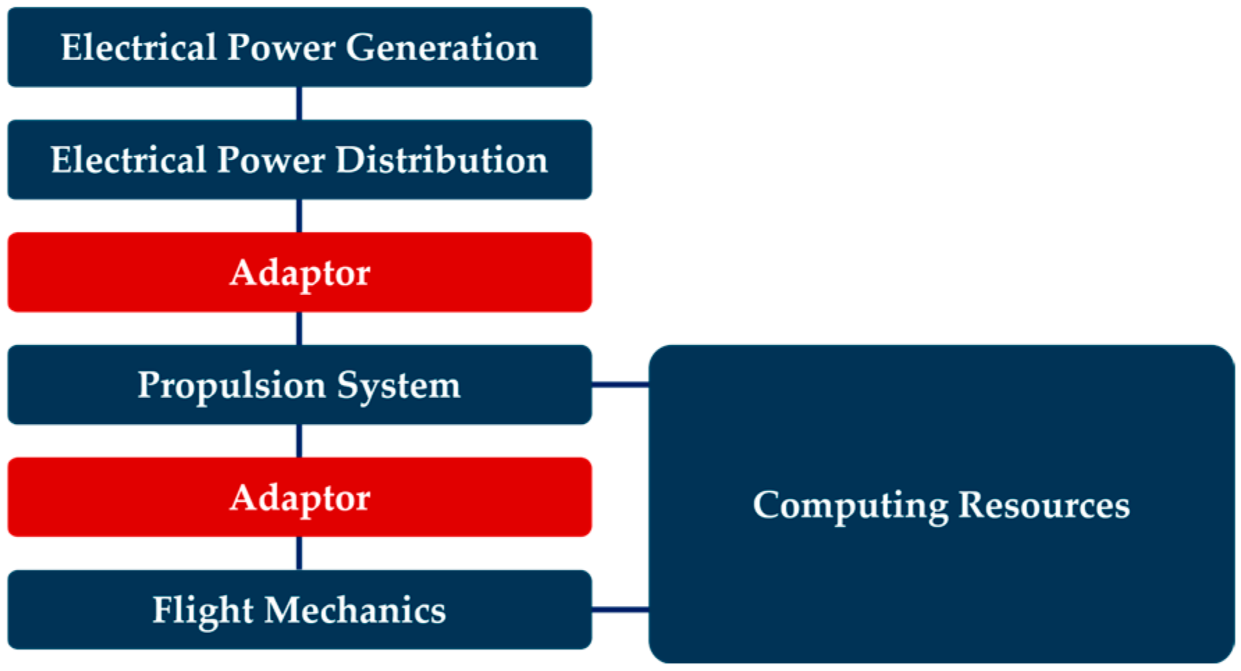
Simcenter™ System Architect 2410 [11], an environment for creation of heterogeneous system simulation architectures, is adopted to define the behavioral model since it allows to integrate models from a dissimilar toolchain in the most possible agnostic way. As shown in Figure 4, the global model is composed of:
Figure 4.
Structure of the behavioral model. The adaptors in the red box are interfaces between the different FMUs.
- Flight Mechanics, a point mass model described by Nonlinear Aircraft Performance Equations in MATLAB®/Simulink® R2024b and based on a custom aerodynamic database. This part is widely described in the companion paper [12].
- Electrical Power Generation and Distribution is realized in Simscape™ R2023b, while the Smart Electric Power Management in MATLAB®/Simulink® R2023b. The latter implements the hybridization function adjusting the torque reference of the electric motor based on the different flight phase.
- Propulsion System in Simcenter™ Amesim™ 2310 [13], a systems simulation platform to virtually assess systems performance. Effects of both thermal engine and electric motor are modeled.
Aerodynamic and Propulsion System models are provided by the Hybrid-Electric Regional Architecture (HERA) consortium [14] through a Cooperation Agreement and cannot be disclosed. Flight Mechanics and Electrical Power Generation and Distribution are exported as Functional Mock-up Units (FMUs) [15] to be integrated in Simcenter™ System Architect, whereas a direct integration can be performed for the Propulsion System. During the integration, custom-made interfaces with the Propulsion System (called adaptors in Figure 4) are introduced. In fact, Simcenter™ Amesim™ uses ports with multiple input and output signals, where each port could be of different nature (e.g., mechanical). Hence, it is not possible to simply demux the signals, and the adaptors become necessary.
2.4. Optimization Analysis
modeFRONTIER® 2025R2 [16], a tool allowing to integrate behavioral models and performing MDAO, is adopted. In order to highlight possible critical steps, an incremental approach is followed for MDAO. Starting from several architectures summarized in Table 1, the All-At-Once was selected as a first step because it represents a conservative benchmark for evaluating the performance of the modeFRONTIER® adaptor, resulting in a more straightforward implementation of the Multi-Disciplinary Analysis (MDA), i.e., the part of MDAO architecture focused on handling residuals.
Table 1.
MDAO architectures features.
Thus, a single macromodel in Simcenter™ Amesim™ describing the entire SoI is integrated in modeFRONTIER® to speed up the analysis due to its reduced computational time. The identified inputs, objectives, and constraints are listed in Table 2. The decision to try minimizing Maximum Take-Off Weight (MTOW) is due to the fact that, compared to a conventional configuration, a hybrid powertrain greatly increases the mass of the vehicle [17]. As a first step, linear relationships are considered between:
Table 2.
MDAO inputs, objectives and constraints.
- The mass of the electric motor () and its power ();
- The mass of the battery () and its capacity ().
As MTOW changes with and , values of wing reference surface are updated:
with and referred to the baseline configuration. In this way, the “snowball effect” could be taken into account: the larger the aircraft weight, the bigger the structure will be—as well as the —and thus the higher the fuel burnt, which in turn further increases the weight [18]. The optimized configuration is determined with a trade-off between minimum of MTOW and fuel burnt.
2.5. Integrated Virtual Verification and Validation
The ODP actively supports the Virtual Integrated Verification and Validation (IV&V) process: compared to the traditional V cycle, where Verification and Validation activities start at a later stage, in Virtual IV&V they begin during the definition/design phase. In fact, models are continuously integrated, thus allowing Model-in-the-Loop verification from the beginning of the design phase. As a result, many errors are anticipated with respect to the traditional V-cycle. This, together with the higher efficiency of the ODP, brings to a reduction in lead time and increase in cost effectiveness [1].
3. Open Digital Platform
Even though at the end of the project ODP will combine MBSE, MDO, PLM, and SDM technologies, at this stage only the MDO module has a maturity level that allows for the evaluation of its benefits.
3.1. modeFRONTIER® Adaptor
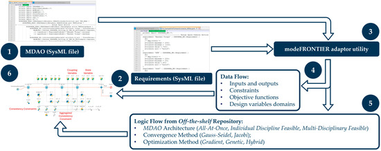
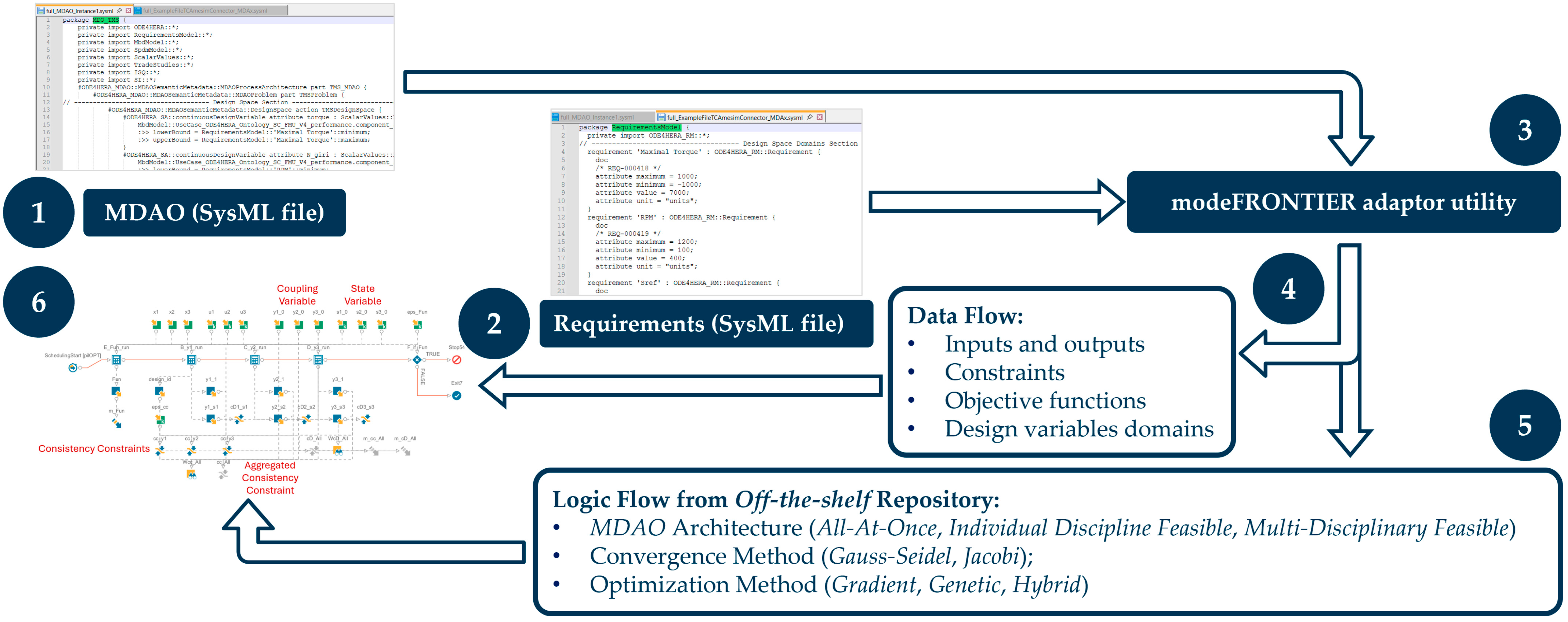
The MDAO module relies on a modeFRONTIER® adaptor, i.e., a Python 3.12 script that converts input data from SysML v2 files into new ready-to-use files by modeFRONTIER® thus generating the optimization workflow. Figure 5 outlines the main steps to follow:
Figure 5.
MDAO supported by modeFRONTIER® adaptor.
- The inputs are represented by two SysML v2 files. The first one is generated by the MDAx tool and stores input and output variables, constraints, objective functions, etc. MDAx is a framework from DLR to formulate MDAO workflows by automatically matching tool inputs to outputs [5].
- The second SysML v2 file contains lower and upper bounds and thresholds of constraints.
- Then the modeFRONTIER® adaptor, implemented in Python, can be run to generate text and .json files, and to automatically open the workflow template.
- Inputs, outputs, constraints, objectives, and design variables domains are automatically imported from the .json file. If performed manually, this task is time-consuming and could easily introduce errors, especially when there is a large number of input/output nodes or design variables domains. In contrast, the adaptor abruptly reduces this effort and the risk of mistakes.
- The user loads the workflow from an off-the-shelf repository and selects the optimization algorithm. After that, some manual integrations into the automatically generated workflow are needed (e.g., for comparing the target curves with the computed ones to verify the constraints).
- Once the run has ended, the user selects the best solution and exports it to a .des file. Then, the second part of the adaptor (called writer) updates the original SysMLv2 file to exchange the updated values with the rest of the ODP.
3.2. Assessment of modeFRONTIER® Adaptor Capabilities
In order to effectively assess the capabilities of the modeFRONTIER® adaptor, additional variables with respect to those from Table 2 are considered. In detail, the assessment is performed with 27 design variables and 41 outputs. Additional inputs are kept constant during the optimization, and the other outputs are not involved in any objective. Then “integration” is selected as a suitable metric to evaluate the MDAO module. In detail, it refers to the process of combining multiple applications or systems to function as a unified whole [19]. In the context of ODP, integration is the ability to seamlessly combine different models (functional, logical, and behavioral) and exchange data across various phases of the product lifecycle involving different tools, domains, and disciplines. This metric can be evaluated using the “Time required for integrating existing tools, models, and data” as the indicator. A procedure based on the “Task Time Estimation via Decomposition” approach is adopted to break down complex activity into smaller tasks, as shown in Table 3.
Table 3.
Assessment of modeFRONTIER® adaptor capabilities based on integration time.
It is evident that the adaptor reduces the manual actions for users, as well as the manual errors. Moreover, the analyzed case is conservative: the optimization workflow is based on one integrated discipline and the All-At-Once architecture is simple to implement manually because it does not require the direct management of coupling between disciplines. Furthermore, the human labor needed for some tasks is proportional to the amount of data flow entities. However, in this case, the number is not large in the context of aeronautic design and the resulting estimation can again be considered conservative.
Since most of the ODP modules are currently under development, only a qualitative analysis of the impacts of modeFRONTIER® adaptor on IV&V phase could be provided:
- The traceability and automation of repetitive tasks reduce the manual errors thus accelerating the Virtual IV&V process. Even errors due to misinterpretation of inputs from previous phases are minimized thanks to the usage of SysML v2 files defined automatically by other ODP modules.
- Some requirements could be automatically implemented as constraints in MDAO using the modeFRONTIER® adaptor thus making their testing unnecessary.
4. Conclusions and Outlook
At first, the entire design cycle is executed using state-of-the-art tools to estimate the efforts needed to develop HER configurations with standard industrial practices and the desired capabilities of the platform. Then, by analyzing the modeFRONTIER® adaptor, it has emerged that the ODP could significantly increase efficiency thanks to the automatization of manual time-consuming tasks and to the traceability among the tools.
In the future, the approach adopted to study the MDAO module could be extended to the entire ODP to evaluate its benefits across the entire design process. Moreover, the SoI will be extended by including other Aircraft Systems and more complex models. Regarding the modeFRONTIER® adaptor, new functionalities are being implemented (e.g., the automation of the result writing function and management of the entire Pareto Curve) and other MDAO architectures will be tested.
Author Contributions
Conceptualization, A.T. and P.B.; methodology, A.T. and P.B.; software, A.T., P.B., E.A., G.C., D.C., V.P., F.R. and N.S.; validation, A.T., P.B., G.C., D.C., V.P., A.R., F.R. and N.S.; formal analysis, A.T., P.B., G.C., D.C., V.P., A.R., F.R. and N.S.; investigation, A.T., P.B., G.C., D.C., V.P., A.R., F.R. and N.S.; resources, P.B., V.P., A.R. and F.R.; data curation, A.T., P.B., G.C., D.C., V.P., A.R., F.R. and N.S.; writing—original draft preparation, A.T.; writing—review and editing, A.T., P.B., E.A., G.C., D.C., V.P., A.R., F.R. and N.S.; visualization, A.T., V.P. and N.S.; supervision, P.B.; project administration, A.T. and P.B.; funding acquisition, P.B., V.P., A.R. and F.R. All authors have read and agreed to the published version of the manuscript.
Funding
Co-Funded by the European Union (project number: 101140510). Views and opinions are, however, those of the author(s) only and do not necessarily reflect those of the European Union or Clean Aviation Joint Undertaking. Neither the European Union nor the granting authority can be held responsible for them.
Data Availability Statement
Restrictions apply to the availability of these data. Except for those shown in the paper, data were obtained from the HERA consortium and are not available for release.
Acknowledgments
The project ODE4HERA is supported by the Clean Aviation Joint Undertaking and its members.
Conflicts of Interest
Authors Andrea Terracciano and Pierpaolo Borrelli were employed by Leonardo S.p.A. Authors Elias Allegaert and Fabien Retho were employed by Siemens Industry Software SAS. Authors Gerardo Carbonaro and Alfredo Renzetti were employed by Aeromechs S.r.l. Authors Vito Primavera and Novella Saccenti were employed by EnginSoft S.p.A. The remaining authors declare that the research was conducted in the absence of any commercial or financial relationships that could be construed as a potential conflict of interest. The funders had no role in the design of the study; in the collection, analyses, or interpretation of data; in the writing of the manuscript; or in the decision to publish the results.
Abbreviations
The following abbreviations are used in this manuscript:
| FMU | Functional Mock-Up Unit |
| HER | Hybrid-Electric Regional |
| HERA | Hybrid-Electric Regional Architecture |
| IV&V | Integrated Verification and Validation |
| MBSE | Model Based System Engineering |
| MDA | Multi-Disciplinary Analysis |
| MDAO | Multi-Disciplinary Analysis Optimization |
| MTOW | Maximum Take-Off Weight |
| ODE4HERA | Open Digital Environment for Hybrid-Electric Regional Architecture |
| ODP | Open Digital Platform |
| PLM | Product Lifecycle Management |
| RCE | Remote Component Environment |
| SDM | Simulation Data Management |
| SoI | System of Interest |
| TLAR | Top Level Aircraft Requirement |
| TRL | Technology Readiness Level |
References
- Grant Agreement Project 101140510—ODE4HERA. Unpublished Document. Available online: https://cordis.europa.eu/project/id/101140510/results (accessed on 1 September 2025).
- Boden, B.; Flink, J.; Mischke, R.; Schaffert, K.; Weinert, A.; Wohlan, A.; Ilic, C.; Wunderlich, T.; Liersch, C.M.; Goertz, S.; et al. Distributed Multidisciplinary Optimization and Collaborative Process Development Using RCE. In Proceedings of the AIAA Aviation 2019 Forum; American Institute of Aeronautics and Astronautics: Washington, DC, USA, 2019. [Google Scholar]
- Heath, C.M.; Gray, J.S. OpenMDAO: Framework for Flexible Multidisciplinary Design, Analysis and Optimization Methods; NASA Glenn Research Center: Cleveland, OH, USA, 2012. [CrossRef] [Scilit]
- Boggero, L.; Lefèbvre, T.; Vankan, J.; Beijer, B.; Saluzzi, V.; Nagel, B. The AGILE 4.0 MBSE-MDAO Development Framework: Overview and Assessment. In Proceedings of the ICAS 2022 Conference, Paper ICAS2022-0615; International Council of the Aeronautical Sciences: Bonn, Germany, 2022. [Google Scholar]
- Page Risueño, A.; Bussemaker, J.H.; Ciampa, P.D.; Nagel, B. MDAx: Agile Generation of Collaborative MDAO Workflows for Complex Systems. In Proceedings of the AIAA Aviation 2020 Forum, Virtual Event, 15–19 June 2020; American Institute of Aeronautics and Astronautics: Washington, DC, USA, 2020; Available online: https://zenodo.org/record/4672051/files/MDAx.CollaborativeMDAO.AIAA2020-3133.pdf (accessed on 1 September 2025).
- Bussemaker, J.H.; Ciampa, P.D.; Nagel, B. From System Architecting to System Design and Optimization: A Link Between MBSE and MDAO. In Proceedings of the INCOSE International Symposium; International Council on Systems Engineering: Detroit, MI, USA, 2022. [Google Scholar]
- Object Management Group (OMG). Systems Modeling Language v2 Specification. Available online: https://www.omg.org/sysml/sysmlv2/ (accessed on 2 January 2026).
- Piscopo, G. HERA-D5.1.2.3A-UERA Concept Aircraft and Regional Demo Aircraft Configuration. Leonardo S.p.A., Pomigliano d’Arco, Italy. 2025; manuscript in preparation.
- Aleksandraviciene, A.; Morkevicius, A. MagicGrid Book of Knowledge; Vitae Litera: Kaunas, Lithuania, 2018. [Google Scholar]
- Cameo Systems Modeler™. Available online: https://www.3ds.com/products/catia/no-magic/cameo-systems-modeler (accessed on 26 November 2025).
- Simcenter™ System Architect Software. Available online: https://plm.sw.siemens.com/en-US/simcenter/integration-solutions/system-architect/ (accessed on 26 November 2025).
- Ciliberti, D.; De Marco, A.; Nicolosi, F. Development and integration of a Flight Dynamics module into the ODE4HERA Open Digital Platform. Eng. Proc. 2026; under review.
- Simcenter™ Amesim™ Software. Available online: https://plm.sw.siemens.com/en-US/simcenter/systems-simulation/amesim/ (accessed on 26 November 2025).
- Hybrid-Electric Regional Architecture. Available online: https://cordis.europa.eu/project/id/101102007 (accessed on 22 November 2025).
- Functional Mock-Up Interface. Available online: https://fmi-standard.org/ (accessed on 22 November 2025).
- modeFRONTIER®. Available online: https://engineering.esteco.com/modefrontier/ (accessed on 26 November 2025).
- Thauvin, J. Exploring the Design Space for a Hybrid-Electric Regional Aircraft with Multidisciplinary Design Optimisation Methods. Ph.D. Thesis, Institut National Polytechnique de Toulouse (Toulouse INP), Toulouse, France, 2018. [Google Scholar]
- Pettes-Duler, M.; Roboam, X.; Sareni, B. Integrated Optimal Design for Hybrid Electric Powertrain of Future Aircrafts. Energies 2022, 15, 6719. [Google Scholar] [CrossRef] [Scilit]
- Integration vs. Interoperability: What’s the Difference? Available online: https://www.spok.com/blog/integration-vs-interoperability-whats-difference/ (accessed on 22 November 2025).



Disclaimer/Publisher’s Note: The statements, opinions and data contained in all publications are solely those of the individual author(s) and contributor(s) and not of MDPI and/or the editor(s). MDPI and/or the editor(s) disclaim responsibility for any injury to people or property resulting from any ideas, methods, instructions or products referred to in the content. |
© 2026 by the authors. Licensee MDPI, Basel, Switzerland. This article is an open access article distributed under the terms and conditions of the Creative Commons Attribution (CC BY) license.