


Abstract
This paper extends the continuous movable parameterisation framework to allow for the consideration of gust load alleviation in the movable layout optimisation process. A finite impulse response filter was introduced to model the feed-forward controller and allow for the dynamic response of the movables. The extended framework was demonstrated using an ultra-high-aspect-ratio cantilever wing aircraft model. The optimisation reduced the root bending moment by 46% when both the wing movables and horizontal tailplane were used, and by 14% when only the wing movables were available. The optimisation positioned the movables to satisfy the handling qualities constraint, while having the largest effect on the root bending moment. Finally, the results show that the framework can be efficiently used to explore the movable layout design space.
1. Introduction
The current drive for reduced and improved fuel efficiency pushes new aircraft designs towards lighter, more flexible designs. The increased flexibility can degrade the aircraft’s performance if not managed properly. One way to account for the flexibility is the use of multifunctional movables [1], which combine attitude and trajectory control with load and aerodynamic performance control. This idea is not new, with such systems having been in development since the 1970s, as shown by the review paper by Regan and Jutte [2].
Current research [3,4,5] shows successful applications of multifunctional movables to reduce fuel burn or reduce manoeuvre and gust loads. However, these works considered wings with internal fuel storage, which limits the design space available to the wing movables. The consideration of novel fuels changes the storage requirements. For example, when considering hydrogen, fuel cannot be stored in the wing anymore. Because there are no internal fuel tanks, such wings expand the structural and geometric design space available to trailing edge (TE) movables.
For the efficient exploration of the increased design space, we have previously developed a continuous movable parameterisation framework [6]. In this paper, we extend the capability of the framework to include gust load alleviation (GLA) within the movable layout optimisation process.
2. Methodology
This section describes the methodology used to implement the GLA capability inside the continuous movable parameterisation framework. First, the continuous movable parameterisation is briefly introduced. This is followed by a discussion on the changes made to the framework to include the GLA capability.
2.1. Continuous Movable Parameterisation
The goal of this section is to introduce the reader to the previously developed continuous movable parameterisation framework [6]. The framework utilises the doublet lattice method (DLM) to model the aerodynamics. The forces generated using DLM consist of three components. They are the steady aerodynamic forces, , the the gust aerodynamic force, , and the unsteady aerodynamic forces, [7], which are summed together to create the total aerodynamic forces seen by the aircraft:
is calculated using the free-stream dynamic pressure , the aerodynamic integration matrix , the aerodynamic influence coefficient, , and the downwash vector, , as follows:
The different downwash contributions are the rigid body motion, , movables, , flexible deformation, , flexible motion , and the camber, .
Considering both the steady and unsteady downwash components in Equations (1) and (2), one can write the aerodynamic forces due to control surfaces,, as follows:
The downwash due to control surface deflection, in Equation (3), contains both the steady and unsteady downwash components. Furthermore, as and are functions of the panel discretisation, and is a function of the flight point, is proportional to .
To describe , our novel methodology uses a B-spline surface
which uses the B-spline control points, , and the B-spline basis functions of degree p and q, , that are generated using the Cox-de Boor recursion formula [8].
The downwash distribution can be optimised to meet the specified objective. This distribution can then be interpreted as the intended movable position and deflection angle.
2.2. Gust Load Alleviation
To accommodate the inclusion of a CS25 gust, the framework needs to be expanded, as in this case, the aircraft experiences time-dependent loading. Hence, the movables need to be able to provide a dynamic response. The dynamic response can be achieved in two ways. First, one could directly prescribe the motion of each control surface. This results in a high number of design variables, as one needs to provide the movable position at each timestep, which is different for each gust length. Secondly, one could include a controller in the simulation loop, where the controller parameters can be optimised to provide maximum load alleviation for any gust length. The inclusion of a GLA controller is preferred due to the lower number of design variables necessary, and to ensure that the movable motion can be achieved in reality. Multiple types of controllers exist, such as a feedback controller, shown in Figure 1a, which updates the movable deflection based on the system response. Another example is a feed-forward controller, shown in Figure 1b, which uses a reference signal, such as the angle of attack (AoA), to pass the required movable deflection to the aeroelastic model. The inclusion of a controller into the aeroelastic plant creates a control co-design problem, as both the controller parameters and the downwash values need to be determined.
Figure 1.
Different controller options. (a) Feedback controller. (b) Feed-forward controller.
In this case, the decision was taken to use a feed-forward controller that uses the AoA probe as the reference signal. This probe is always present on large transports. According to current research, the ability to use a feed-forward controller becomes increasingly beneficial with developments in LIDAR gust detection [9], which enables the aircraft to prepare for gust encounters at an even earlier stage.
To represent the feed-forward controller, we use a digital finite impulse response (FIR) filter. The coefficients of the FIR filter allow us to represent any controller behaviour. One benefit of the FIR filter is that it can never become unstable, provided the coefficients are bounded and small changes in the coefficients result in small changes in the filter’s response [10,11].
To model the FIR filter, one uses the z-transfer function of the FIR filter as follows [11]:
with h being part of the FIR filter coefficient vector, , and being one of the design variables available to the optimiser. Furthermore, N indicates the number of FIR coefficients, and z the z-transform variable. The z-transform is the discrete time equivalent of the Laplace transform.
Rewriting Equation (5) as an input–output relation and performing the inverse z-transform results in the following discrete time input–output relation [11]:
In Equation (6), is the discrete time output, and indicates the time-delayed discrete angle of attack measurement, which is the reference signal.
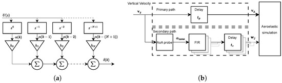
The architecture in Figure 2a illustrates the process described above, as it creates a discrete time sampled signal that is then multiplied by the corresponding FIR coefficients. The response of the multiplication is summed together to create a discrete time filter response.
Figure 2.
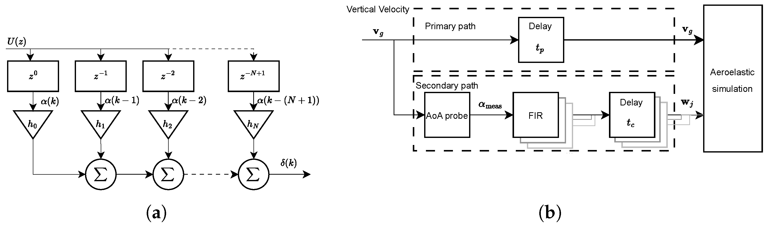
Feed-forward controller implementation. (a) FIR filter implementation. Adapted from Wildscheck [10]. (b) FIR filter control scheme. Adapted from Binder et al. [5].
For the implementation inside the framework, illustrated in Figure 2b, the vertical gust velocity is measured using the AoA probe, and the corresponding AoA is passed towards the FIR filters, with the downwash delayed by seconds to account for the computation time of the controller, after which it is applied to the aeroelastic model. It should be noted that because the CS25 gust is included as a one-dimensional gust profile, the AoA measurement at the probe is uniform along the span. Furthermore, the time delays in the primary and secondary paths are dependent on the position of the centre of pressure of each DLM panel and the flight speed. In the secondary path, instead of the absolute position, the distance between the AoA probe and the movable region is used.
3. Application
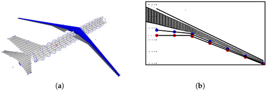
To demonstrate the implementation of the GLA capability in the continuous movable parametrisation framework, an ultra-high-aspect-ratio cantilever wing with an aspect ratio of 19 and a span of is used. It is modelled as a free-flying aircraft; hence, we have loads due to the aircraft’s flexibility and its rigid body motion. An overview of the model is shown in Figure 3a.
Figure 3.
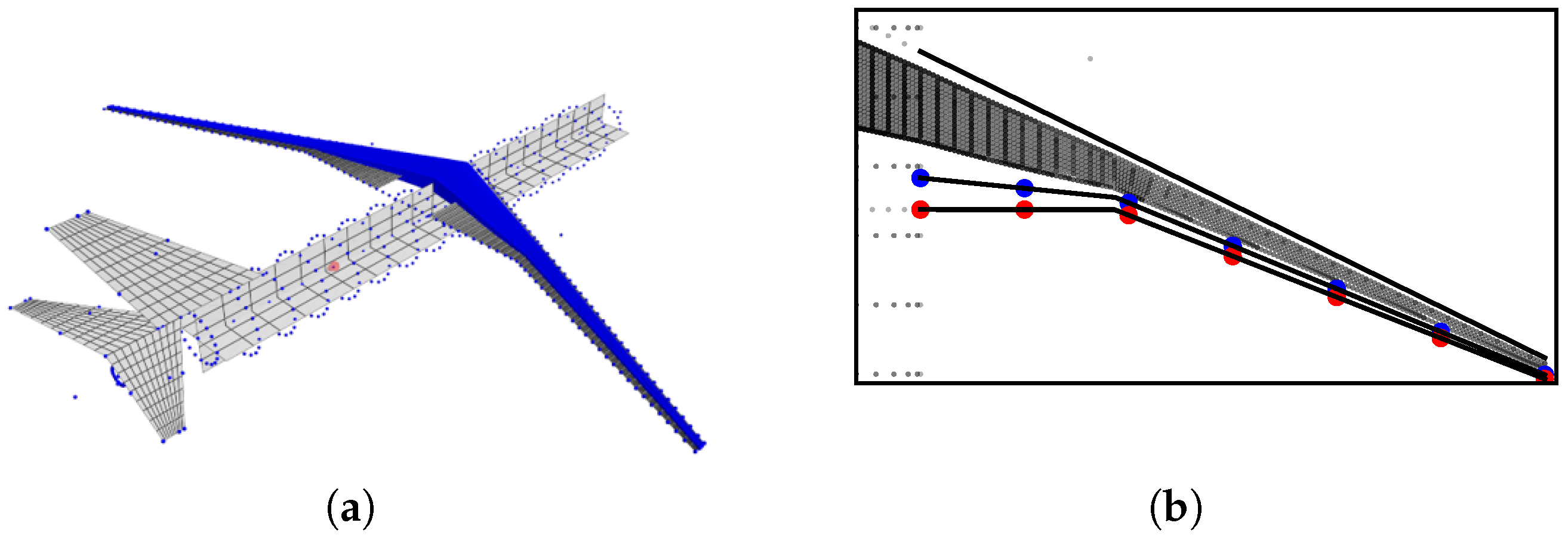
Aircraft model and movable region. (a) Isometric view of the aircraft model. (b) Movable region. Dots indicate spanwise position of the B-spline control point grid on the movable leading edge (blue) and trailing edge (red).
During the optimisation process, a single flight point at a Mach number M = 0.78 and an altitude of FL300, approximately 10 km, is considered. The movable region available for the optimiser is shown in Figure 3b. The B-spline is generated on a 20% chord fraction along the TE using seven spanwise control points.
4. Optimisation Problem
The optimisation problem considered is written as follows:
The objective function is the , which is the largest difference between the root bending moment (RBM) at 1 g trim and the RBM seen during the gust encounter. The loads at the wing root were taken, as this is one of the main drivers that are considered during wing sizing [4]. The of the RBM was taken, because if , the aircraft feels no perturbation during the gust encounter, hence ensuring that the loads remain constant. The design variables, , available to minimise the , are the FIR filter coefficients and the downwash at the B-spline control points. An overview of the different constraints considered is given in Table 1.
Table 1.
Constraint overview.
The constraints in Table 1 consist of a set of limit loads, , determined using a set of extreme manoeuvres. A set of deflection limits for the flap, , aileron, , and the summation of the flap and aileron in the flaperon. Furthermore, the roll rate constraint, , is necessary to ensure that certification requirements concerning handling qualities (HQ) are met, and the angle of attack constraint, , and elevator deflection angle constraint, , ensure that the lift performance is not overestimated. Finally, the downwash coupling constraint, , is the coupling constraint between the GLA and HQ analyses.
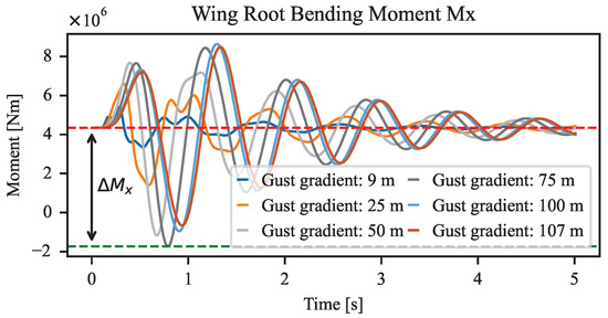
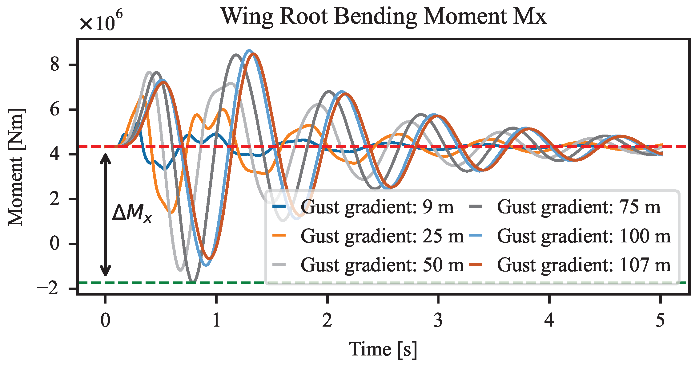
As the is minimised in Equation (7), the largest needs to be determined. This is done through analysing six open-loop gust encounters with gust gradients varying from 9 m to 107 m. The RBM corresponding to these simulations is shown in Figure 4. When the loads are compared to the 1 g trim loads, the largest is found for a 75 m gust gradient, with this serving as an input for the GLA optimisation process.
Figure 4.
Open-loop wing root bending moment for different gust gradients.
5. Results
This section describes the results obtained using the optimisation framework. First, Section 5.1 presents the GLA results using the horizontal tailplane (HTP) and the wing movables, after which Section 5.2 shows the results using only the wing movables. Finally, Section 5.3 presents and discusses the effect of adding movable rate limits on GLA performance.
5.1. GLA Movable Layout Using HTP and Wing Movables
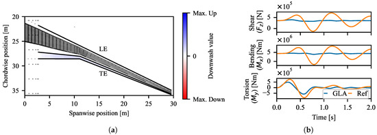
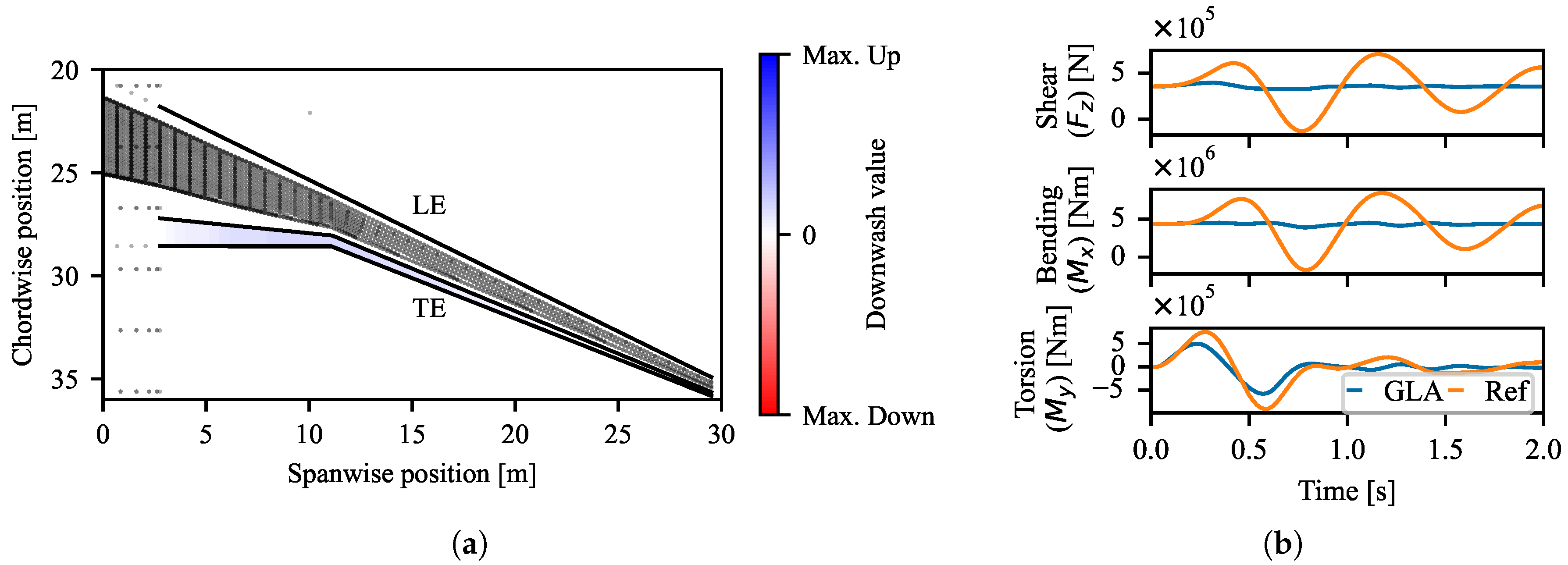
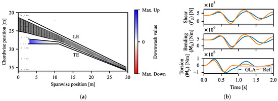
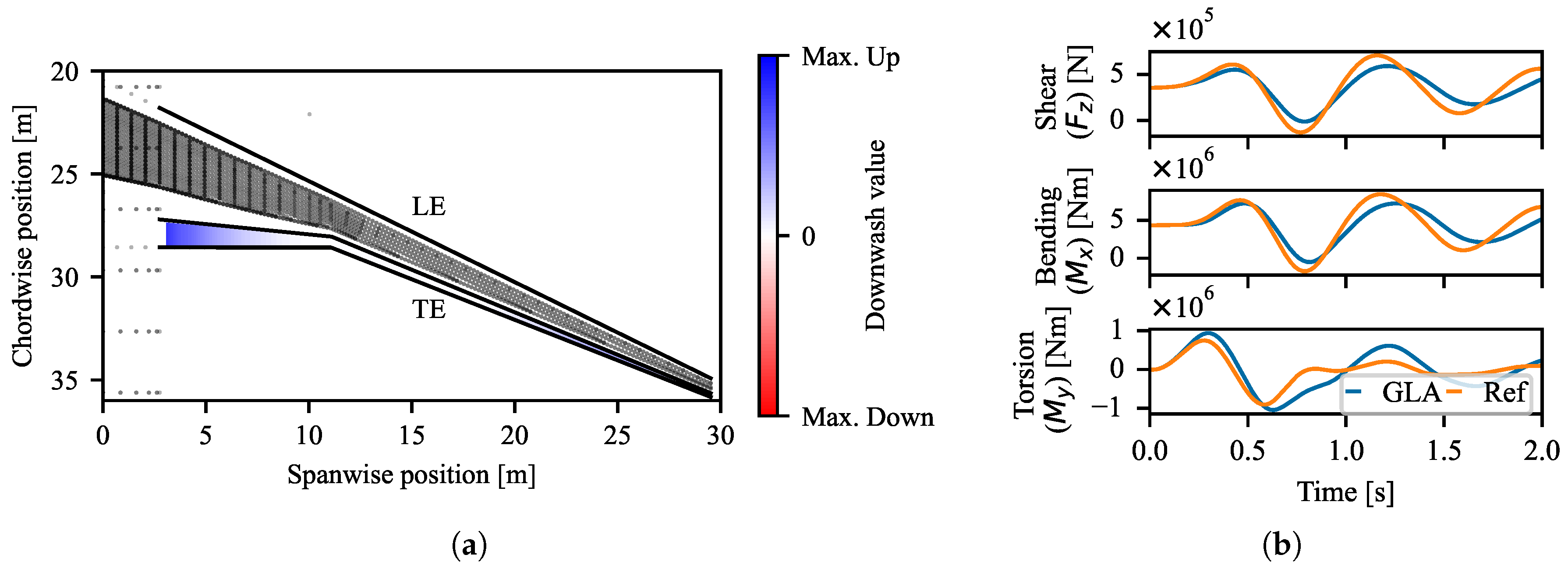
In the first optimisation, the GLA controller was applied to the HTP and the downwash control points on the wing. Figure 5a shows the downwash distribution on the right wing corresponding to a right roll. Hence, it is in line with expectations that the movables show an upward deflection. The downwash distribution in Figure 5a shows that the downwash is centred between 10 and 15 m semi-span, allowing for the HQ requirements to be met. This downwash location is also used by the wing movables during GLA.
Figure 5.
HQ-GLA optimisation results using the wing movables and the HTP. (a) Downwash distribution on the right wing for a right roll. (b) Loads seen during gust encounter.
The root loads seen during the reference and GLA case are plotted in Figure 5b. The use of the HTP and wing movables shows a large reduction in the shear force and bending moment, with these loads showing a small amount of perturbation compared to the 1 g trim loads. The 1 g trim loads can be seen in Figure 5b at time = 0 . Comparing the shear force and bending moment to the open-loop response, the optimised FIR filter and downwash distribution reduce the shear force by 43% and the bending moment by 46%. For the torsional moment, a reduction of 35% was found.
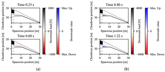
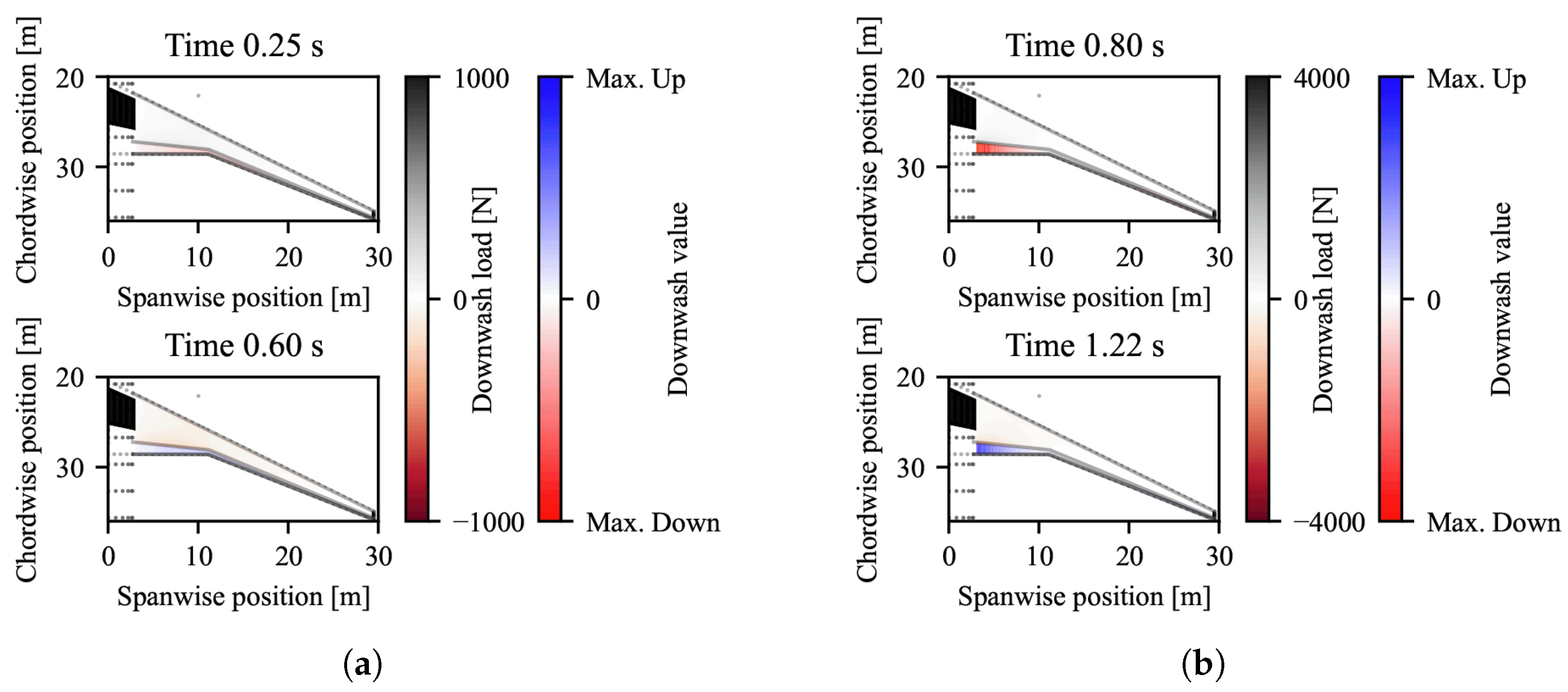
Investigating the HTP deflection during the gust encounter, a deflection range of 10° was found. The largest upward and downward downwash values, presented in Figure 6a, are found to be equivalent to a deflection range of 6°. Hence, it can be concluded that the largest contributing factor to the reduction of is the HTP.
Figure 6.
GLA downwash and downwash load distributions showing largest downwash values, and load generated due to applied downwash during gust encounter. (a) GLA with HTP and wing movables. (b) GLA using wing movables only.
5.2. GLA Using Wing Movables
Because the results of the optimisation using the wing movables and the HTP found that the HTP is the main contributor to reducing root bending moments seen during the gust encounter, an optimisation of the movable layout using only the wing movables has also been performed. Figure 7a shows the downwash distribution for a right roll. Here, two movable regions appear. The first region, positioned around the 5 m semi-span, is deflected to its maximum value to ensure the HQ requirements are met. The second movable region, between 20 and approximately 30 m semi-span, has a lower amount of downwash applied, ensuring that the moment arm required for rolling is sufficiently large. This region also controls the lift in the tip region, helping the total lift to get as close as possible to the 1 g trim lift during the gust encounter.
Figure 7.
HQ-GLA optimisation results using only the wing movables. (a) Downwash distribution on the right wing for a right roll. (b) Loads seen during gust encounter.
The root loads seen during the gust encounter are plotted in Figure 7b, which shows a reduction in the shear force and bending moment. Compared to the open-loop gust encounter, the shear force is reduced by 16%, whereas the bending moment is reduced by 14%. However, it can also be concluded that using the wing movables causes an increase in the torsional moment, which was found to increase by 15% compared to the open-loop response.
The increase in torsional moment at the wing root is caused by the large variations in downwash in the inboard movable region, shown in Figure 6b, as well as the large chord of the movables in this region. The inboard downwash is used to actively control the AoA of the aircraft, which allows for the reduction in the RBM. This behaviour is expected, as keeping the AoA as close as possible to the 1 g trim case results in the smallest perturbations experienced by the aircraft.
5.3. Effect of Rate Limits
The results presented in the previous subsections were obtained without considering rate limits. As a preliminary study, the effect of rate limits has been considered using the optimised FIR coefficients of the wing-only case.
The rate limit applied to the wing movables was 50°/s, which is a typical value for GLA applications [12]. Rate-limiting the optimised wing-only downwash distribution showed that a maximum RBM reduction of only 3% could be achieved, compared to the 14% reduction without the rate limits. Because of the large difference in achievable RBM reduction, the effect of rate limits on the movable layout must be studied when optimising the positions of the different movables.
6. Conclusions
The work presented in this paper demonstrates the successful extension of gust load alleviation (GLA) to the novel movable parameterisation methodology. The extended methodology has been applied to an ultra-high-aspect-ratio cantilever wing, demonstrating the framework’s ability to explore the movable positioning design space.
Two GLA configurations have been studied. The first investigated the effect of using the horizontal tailplane (HTP) and the wing movables for GLA. The second configuration considered GLA performance using only the wing movables. Using the combined capability of the HTP and wing movables allowed for a 46% reduction in the root bending moment (RBM) compared to the open-loop response. It was found that the HTP made a significant contribution to the RBM reduction, as it enabled the aircraft to prepare for gust encounters. Hence, the effect of using only the wing movable was investigated, and an RBM reduction of 14% was found, showing that using the HTP allowed for a 32 percentage points larger RBM reduction.
Future work will involve coupling the handling qualities (HQ)-GLA optimisation framework to the existing HQ–manoeuvre load alleviation (MLA) framework, allowing for the study of combined manoeuvre and gust loads on the optimised movable layout. The effect of different rate limits on the wing and tail movables also needs to be investigated, as the rate limit has a large effect on the achievable RBM reduction. Finally, the effect of different types of unconventional planforms, such as strut-braced wings or Prandtl-Planes, on the movable layout can be investigated.
Author Contributions
S.d.B.: conceptualisation, methodology, software, writing—original draft, review and editing, visualisation. J.S.: writing—review and editing, supervision, funding acquisition. R.D.B.: writing—review and editing, supervision, funding acquisition. All authors have read and agreed to the published version of the manuscript.
Funding
The work presented herein has been partially funded by the European Community’s Clean Aviation programme under the Grant Agreement 101101974. The UPWing project (Ultra-Performance Wing) is a project funded under the topic Climate, Energy and Mobility, involving 26 partners. The project started on 1 January 2023. Disclaimer: Views and opinions expressed are, however, those of the authors only and do not necessarily reflect those of the European Union or Clean Aviation Joint Undertaking. Neither the European Union nor the granting authority can be held responsible for them.

Institutional Review Board Statement
Not applicable.
Informed Consent Statement
Not applicable.
Data Availability Statement
Not applicable.
Acknowledgments
The authors would like to thank Charly Mollet and Lander Vertonghen from ONERA-MSAE/MC2 for providing the aircraft model. Furthermore, the authors would like to thank Eric Nguyen Van and Sébastien Defoort from ONERA-DTIS for providing the aircraft mission. Artificial intelligence (AI) was utilised in the writing process to assist with language refinement and clarity. All AI-generated content was reviewed and verified by the authors to ensure accuracy and alignment with the research objectives.
Conflicts of Interest
The authors declare no conflicts of interest.
References
- Reckzeh, D. Multifunctional Wing Movables: Design of the A350XWB and the Way to Future Concepts. In Proceedings of the 29th Congress of the International Council of the Aeronautical Sciences (ICAS), St. Petersburg, Russia, 7–12 September 2014. [Google Scholar]
- Regan, C.D.; Jutte, C.V. Survey of Applications of Active Control Technology for Gust Alleviation and New Challenges for Lighter-Weight Aircraft; Technical Report DFRC-E-DAA-TN4736; NASA: Washington, DC, USA, 2012.
- Muradas Odriozola, D.; Marquier, S.; Morlier, J.; Gogu, C. Control Surface Sizing and Design through Integrated MDO Approach: Enhancing Load Alleviation While Preserving Handling Quality Criteria. In Proceedings of the International Forum on Aeroelasticity and Structural Dynamics (IFASD): Aeroelasticity & Structural Dynamics in a Fast Changing World, Den Haag, The Netherlands, 17–21 June 2024. [Google Scholar]
- Pusch, M.; Knoblach, A.; Kier, T. Integrated Optimization of Control Surface Layout for Gust Load Alleviation. CEAS Aeronaut. J. 2019, 10, 1059–1069. [Google Scholar] [CrossRef] [Scilit]
- Binder, S.; Wildschek, A.; De Breuker, R. The Interaction between Active Aeroelastic Control and Structural Tailoring in Aeroservoelastic Wing Design. Aerosp. Sci. Technol. 2021, 110, 106516. [Google Scholar] [CrossRef] [Scilit]
- de Boer, S.; Sodja, J.; De Breuker, R. Continuous Parametrisation of Wing Movable Layout for Design Optimisation. In Proceedings of the International Forum on Aeroelasticity and Structural Dynamics (IFASD): Aeroelasticity & Structural Dynamics in a Fast Changing World, Den Haag, The Netherlands, 17–21 June 2024. [Google Scholar]
- Voß, A. An Implementation of the Vortex Lattice and the Doublet Lattice Method; Technical Report DLR-IB-AE-GO-2020-137; Institut für Aeroelastik, Deutsches Zentrum für Luft- und Raumfahrt: Göttingen, Germany, 2020.
- Piegl, L.; Tiller, W. The NURBS Book; Monographs in Visual Communication; Springer: Berlin/Heidelberg, Germany, 1997. [Google Scholar] [CrossRef] [Scilit]
- Fezans, N.; Joos, H.D.; Deiler, C. Gust Load Alleviation for a Long-Range Aircraft with and without Anticipation. CEAS Aeronaut. J. 2019, 10, 1033–1057. [Google Scholar] [CrossRef] [Scilit]
- Wildschek, A. An Adaptive Feed-Forward Controller for Active Wing Bending Vibration Alleviation on Large Transport Aircraft. Ph.D. Thesis, Technische Universität München, Munich, Germany, 2009. [Google Scholar]
- Elliott, S.J. 2—Optimal and Adaptive Digital Filters. In Signal Processing for Active Control; Elliott, S.J., Ed.; Signal Processing and Its Applications; Academic Press: London, UK, 2001; pp. 49–102. [Google Scholar] [CrossRef] [Scilit]
- Fonte, F. Design and Validation of Active Gust Load Alleviation Systems for Aircraft. Ph.D. Thesis, Politecnico Di Milano, Milan, Italy, 2018. [Google Scholar]



Disclaimer/Publisher’s Note: The statements, opinions and data contained in all publications are solely those of the individual author(s) and contributor(s) and not of MDPI and/or the editor(s). MDPI and/or the editor(s) disclaim responsibility for any injury to people or property resulting from any ideas, methods, instructions or products referred to in the content. |
© 2026 by the authors. Licensee MDPI, Basel, Switzerland. This article is an open access article distributed under the terms and conditions of the Creative Commons Attribution (CC BY) license.