Abstract
Automated Fibre Placement (AFP) enables the rapid and precise manufacturing of composite structures, but the process inherently introduces defects such as gaps and overlaps, which can significantly affect structural performance. Most existing studies assess these effects through coupon-scale testing; however, such an approach may not capture the influence of structural scale and defect interaction. This study investigates the combined effects of specimen dimension and defect configuration on stiffness, strength, and damage evolution. Two characteristic defect patterns were examined—aligned and staggered gaps—across two specimen dimensions. The results reveal different scaling trends for strength and stiffness between the two configurations. They also show the influence of specimen size on damage initiation and delamination behaviour. The findings demonstrate that coupon-based knockdowns cannot be directly extrapolated to structural components without accounting for defect interaction and scale effects.
1. Introduction
Automated Fibre Placement (AFP) has gained popularity for its ability to produce complex structures with precision and efficiency. The process involves laying down pre-impregnated fibre tows (prepreg) using robots and layup heads [1]. Its ability to place and steer individual tows reduces material waste, and allows the manufacturing of laminates with tailored properties such as variable stiffness (VS) [2] and aeroelastic optimisation [3]. However, despite recent advances in AFP manufacturing [4], several types of defects—such as gaps, overlaps, wrinkles, bridging, and local fibre misalignments—can still occur due to a variety of factors, including tool path geometry, steering radius, process parameters, and material behaviour [5].
The accumulation of small deviations can lead to localised imperfections that influence laminate quality and structural performance. Understanding how these defects affect the mechanical response of composite structures is therefore essential for establishing robust design guidelines and quality assurance criteria.
So far, the effect of defects has mainly been studied at the coupon level. Here, studies have shown that AFP defects can lead to reductions in stiffness and strength [6,7,8,9], affecting both baseline structure performance as well as damage tolerance. However, the focus on coupon-level testing leads to the question: are the observed property reductions primarily driven by the absolute characteristics of the defect, or are they influenced by the defect-to-gauge ratio imposed by coupon-scale testing?
The present study aims to address this issue by examining AFP defect characterisation through the lens of scale and interaction, by exploring how defect effects evolve across different specimen dimensions and how interactions between defects influence global performance. The principal conclusion is that both scale and defect interaction play a critical role in determining structural behaviour, highlighting the need for approaches that go beyond coupon-level characterisation when developing reliable design criteria for large aerospace structures.
2. Methodology
2.1. Specimen and Defect Configuration
The specimen geometries and defect layouts were designed to investigate the influence of structural scale and defect interaction on the mechanical response of AFP-manufactured laminates. As shown in Figure 1, two nominal specimen sizes were employed: a small coupon with a gauge dimension of 75 mm × 25 mm, and a large coupon with a gauge dimension of 150 mm × 50 mm, corresponding to a four-fold increase in surface area.
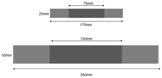
Figure 1.
Small and large specimens’ dimensions.
The small coupons were designed first, and then used as the basis for the development of the larger specimens. Two distinct scaling strategies were adopted for the large coupons: (i) a direct scaled-up version of the small coupon, and (ii) a repeated configuration in which the small coupon layout was replicated two times along both specimen length and width, to preserve the same gap spacing and alignment pattern within the larger specimen.
All configurations incorporated manufacturing gaps with a nominal width of 6.35 mm. To replicate AFP-induced placement defects, these gaps were introduced in the 90° plies of the layup , by deliberately not placing a single tow. The various configurations are summarised below.
- Aligned group
Figure 2a shows the configuration of the aligned group specimens. The Small Aligned specimen contained four aligned gaps located at the centreline of the specimen. The Large 1Aligned configuration was a scaled-up version of the Small Aligned specimen, maintaining four aligned gaps positioned along the centreline within the larger gauge area. The Large 2Aligned configuration contained eight aligned gaps arranged as two sets of four, representing a two-times duplicate of the Small Aligned layout along the width and length of the larger specimen.
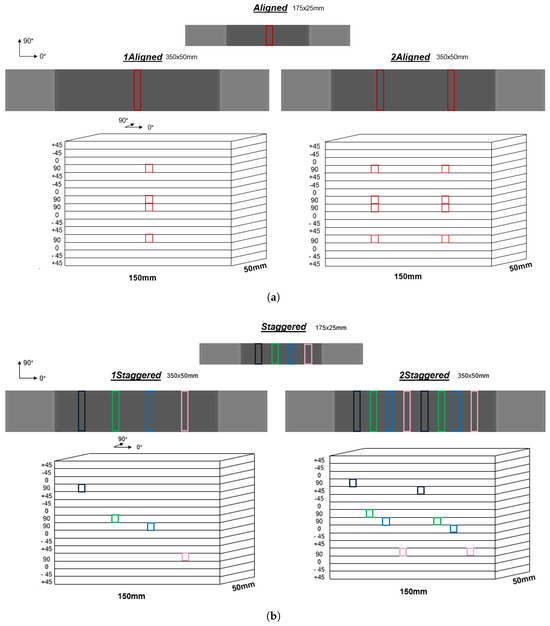
Figure 2.
Defect configuration schematic: (a) Aligned group.(b) Staggered group.
- Staggered group
Analogous to the aligned group, staggered configurations (Figure 2b) were designed to distribute defects along the specimen length. In the Small Staggered specimen, one defect was placed in each of the four 90° plies, with a longitudinal offset of 12.7 mm between successive defects to ensure even spacing along the length. The Large 1Staggered specimen contained four staggered gaps distributed over the larger gauge length, maintaining the same relative offsets. Finally, the Large 2Staggered configuration incorporated eight staggered gaps, representing a double repetition of the Small Staggered pattern in both the 0° and 90° directions within the larger specimen.
2.2. Manufacturing and Test Setup
The laminates containing defects were produced using an AFP system located at the SAM XL research centre. The system comprises an AFP-XS head (ADD Composites) mounted on a KUKA KR 210 R2700 industrial robotic manipulator (KUKA Robotics, Augsburg, Germany). Pristine specimens were manufactured by hand layup. The material used was a thermoset carbon fibre-reinforced polymer (CFRP), Deltapreg unidirectional M30SC-150-DT120-34F, supplied by Toray Group (Tokyo, Japan) as pre-sliced tows with a nominal width of 6.35 mm ( inch).
The laminates were cured in an autoclave at 120 °C with a pressure of 6 bar following a standard cycle as advised by the manufacturer on the technical datasheet [10]. Specimens were cut to size using a Compcut ACS 600 system, then tabbed with GFRP tabs (Hexcel 7581 glass/epoxy) of 1.9 mm thickness that were tapered at an angle of 15°.
A random speckle pattern was applied to the specimen surface to enable full-field strain measurements via three-dimensional Digital Image Correlation (3D DIC, Correlated Solutions, Inc., Columbia, SC, USA). Virtual extensometers were employed to determine axial stiffness, while out-of-plane deformations such as curvature and secondary bending induced by waviness were also captured through DIC analysis. Two acoustic emission (AE) sensors (Vallen Systeme, VS900-M) were mounted on some specimens to detect the onset of delamination during testing. The AE acquisition system was configured with a sampling rate of 2 MHz and a threshold of 55 dB. Ultrasonic C-scan inspections were performed in a water tank for one specimen of each defect configuration at 0%, 55%, 65%, 75% and 85% of failure load, to assess the evolution of delamination. Conducting these inspections required interrupting the load application and removing the specimen from the test rig.
Mechanical testing was conducted under uniaxial tensile loading using a Zwick 250 kN universal testing machine (ZwickRoell, Ulm, Germany) at a displacement rate of 1 mm/min. To prevent slippage during testing of larger specimens, 120-grit mesh sandpaper was applied at the clamping regions.
3. Results
3.1. Strength and Stiffness
Table 1 presents the strength and stiffness values for the different specimen configurations relative to the baseline laminate without defects. Distinct trends are observed between the aligned and staggered defect layouts.

Table 1.
Summary of tensile strength and axial stiffness results for all defect configurations.
For the aligned group, specimen scaling has a clear effect on the measured strength. The strength knockdown increases from 5.4% for the Large 1Aligned specimens to 12.6% for the Small Aligned configuration, indicating a pronounced scale effect on failure strength. In contrast, stiffness is not strongly affected by scaling in these configurations. All aligned configurations exhibit a similar reduction in stiffness of approximately 3%, irrespective of specimen size or number of defects.
The staggered group displays an opposite trend. In this case, the strength is not significantly influenced by changes in specimen configuration, suggesting that staggering mitigates the interaction effects observed in the aligned layouts, which will be explained in the Section 4. However, stiffness shows a clear dependence on specimen configuration: the reduction ranges from 1.4% for the Large 1Staggered specimens to 6.7% for the Large 2Staggered configuration. This observation suggests that staggered gaps primarily affect the initial elastic response rather than the ultimate strength.
3.2. Delamination Behaviour
The delamination patterns were observed to be strongly influenced by the defect configuration. In the aligned group (Figure 3a), edge delamination consistently showed the same characteristic shape and was observed to terminate at the locations of the gaps. This behaviour can be attributed to the presence of the 90° ply gaps located along the laminate mid-plane. These gaps allow local bonding between the adjacent 0° plies, effectively arresting delamination growth at the 0/90° interfaces and creating a series of discrete delaminated regions bounded by the gaps.
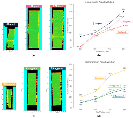
Figure 3.
Delamination evolution from C-scan data: (a) C-scan plots at 75% failure load (aligned group). (b) Delamination area evolution at different % failure loads (aligned group). (c) C-scan plots at 75% failure load (staggered group). (d) Delamination area evolution at different % failure loads (staggered group).
In contrast, for the staggered group, shown in Figure 3c, the gaps did not exert such a clear influence on the overall delamination shape. Instead, specimen dimensions appeared to play a more significant role in governing delamination area. As shown in Figure 3d, the delaminated area evolution, expressed as a percentage of the total surface area, reached approximately 34% and 36% for the Large 1Staggered and Large 2Staggered specimens at 85% of the failure load. In comparison, the Small Staggered specimen exhibited substantially larger delaminated areas, up to 69% under the same load level.
To a lesser extent, a similar trend can be observed within the aligned group in Figure 3b. This is because the delaminated area remained relatively low, with the Small Aligned coupon reaching approximately 25% delaminated area at 85% of the failure load, compared to 69% for the Small Staggered specimen. These observations indicate that both defect interaction and specimen scale can influence delamination behaviour.
3.3. Damage Initiation
Acoustic emission (AE) monitoring was employed to detect acoustic waves generated by damage events during mechanical loading. From the measured AE data, a sentry function (1) was computed to identify the onset of damage, it is defined as the logarithmic ratio between the mechanical energy and the cumulative AE energy. This parameter has been shown to provide valuable insight into the progression of damage within composite laminates, where distinct trends in the sentry function correspond to different stages of damage evolution [11].
where is the mechanical energy (area under the load–displacement curve), is the cumulative AE energy and d is the displacement.
In this study, particular attention was given to sudden drops in the sentry function. As the sentry function represents a ratio, an abrupt decrease indicates either a sharp increase in AE activity, or a sudden drop in stiffness. This suggests the occurrence of a significant event such as the initiation of macro-scale damage.
Figure 4 illustrates the comparison of damage initiation behaviour between the smaller and larger coupon configurations. The vertical markers in the plots indicate the strain levels corresponding to the first sudden drop in the sentry function, which were interpreted as the initiation points of macro-damage. In the aligned group, larger specimens exhibited damage initiation at higher strain levels compared with the smaller coupons. A similar trend was observed for the staggered group, suggesting that specimen scale influences the strain threshold for the onset of damage in AFP-manufactured laminates.
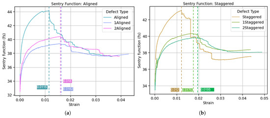
Figure 4.
Sentry function with labelled first sudden drop: (a) Aligned group. (b) Staggered group.
4. Discussion
The experimental results revealed distinct trends in how specimen dimension and defect configuration affect the mechanical response of AFP-manufactured laminates. Opposite sizing trends were observed for the two defect configurations: in the aligned group, specimen dimension significantly influenced tensile strength but had little effect on stiffness, whereas in the staggered group, the influence was reversed, with stiffness being more affected than strength.
These contrasting behaviours can be explained by the different ways in which defects interact within the laminate. In the aligned group, neighbouring gaps are positioned directly along the specimen centreline, resulting in an accumulation of local waviness and increased out-of-plane deformation in the adjacent plies. This compounded waviness promotes local bending and interlaminar stress concentrations that strongly influence failure strength. Furthermore, the 90° ply gaps in the aligned specimens interrupt delamination propagation along the laminate edges by enabling adjacent 0° plies to bond locally. These regions act as delamination arrest points, generating high interlaminar stresses and altering the load redistribution mechanism during progressive failure. As these delaminations stop and their spacing being dependent on specimen size, the overall strength of the laminate becomes scale-sensitive. In contrast, the staggered group exhibits reduced interaction between neighbouring gaps. Their reduced waviness, together with the limited interaction between defects, leads to a relatively constant tensile strength across specimen dimensions. Such behaviour is consistent with the weakest-link theory, where failure is governed by the most critical local defect. However, the staggered defects still induce changes in local strain field, which accumulate across the larger laminate area and lead to measurable changes in global stiffness. The response therefore becomes more sensitive to scale in stiffness than in strength.
5. Conclusions
This study investigated the influence of specimen dimension and defect interaction on the mechanical behaviour and damage development of AFP-manufactured laminates. The results demonstrated that both testing scale and defect configuration significantly affect the observed response.
With increasing specimen dimension, a smaller relative delaminated area was observed at equivalent percentages of failure load, and damage initiation occurred at higher strain levels. These findings indicate that larger specimens exhibit a delayed onset of macro-damage and a more confined delamination evolution compared with smaller coupons. Defect interaction also played a crucial role. The staggered group and aligned group displayed distinct delamination patterns and strain responses, leading to opposite scaling trends between the two configurations.
Overall, the results emphasise that knockdown factors derived from coupon-scale testing cannot be directly extrapolated to structural applications. AFP-induced defects do not act independently; design guidelines should consider their interaction with neighbouring defects, layup position and scale.
Future research should focus on modelling the local damage evolution mechanisms to better understand why larger specimens exhibit smaller delaminated areas and delayed damage initiation. Incorporating these interactions into predictive models would allow the development of more accurate defect tolerance criteria for AFP-manufactured aerospace structures.
Author Contributions
Conceptualisation, L.A. and J.-A.P. and D.P. and R.A.; methodology, L.A. and J.-A.P. and D.P. and R.A.; supervision, J.-A.P., D.P. and R.A.; validation, L.A.; formal analysis, L.A.; investigation, L.A.; visualisation, L.A.; data curation, L.A.; writing—original draft preparation, L.A.; writing—review and editing, L.A. and J.-A.P. and D.P. and R.A.; All authors have read and agreed to the published version of the manuscript.
Funding
This research was conducted within the research and innovation programme “Luchtvaart in Transitie”, which is funded by the Dutch National Growth Fund (Groeifonds). It is part of the “H2Crash” project.
Institutional Review Board Statement
Not applicable.
Informed Consent Statement
Not applicable.
Data Availability Statement
Datasets are not publicly available yet because they are part of an ongoing study.
Acknowledgments
The authors would like to acknowledge André Mendes Florindo (SAM XL) for his help and support in manufacturing the AFP panels.
Conflicts of Interest
The authors declare no conflicts of interest.
References
- Lukaszewicz, D.H.J.; Ward, C.; Potter, K.D. The engineering aspects of automated prepreg layup: History, present and future. Compos. Part Eng. 2012, 43, 997–1009. [Google Scholar] [CrossRef]
- Vijayachandran, A.A.; Davidson, P.; Waas, A.M. Optimal steered fiber paths for maximizing biaxial buckling load of a flat plate manufactured using AFP. In Proceedings of the AIAA Scitech 2020 Forum; American Institute of Aeronautics and Astronautics: Reston, VA, USA, 2020; p. 0165. [Google Scholar] [CrossRef]
- Brooks, T.R.; Kennedy, G.; Martins, J.R.R.A. High-fidelity multipoint aerostructural optimization of a high aspect ratio tow-steered composite wing. In Proceedings of the 58th AIAA/ASCE/AHS/ASC Structures, Structural Dynamics, and Materials Conference; American Institute of Aeronautics and Astronautics: Reston, VA, USA, 2017; p. 1350. [Google Scholar] [CrossRef][Green Version]
- Carosella, S.; Hügle, S.; Helber, F.; Middendorf, P. A short review on recent advances in automated fiber placement and filament winding technologies. Compos. Part Eng. 2024, 287, 111843. [Google Scholar] [CrossRef]
- Harik, R.; Saidy, C.; Williams, S.J.; Gurdal, Z.; Grimsley, B. Automated Fiber Placement Defect Identity Cards: Cause, Anticipation, Existence, Significance, and Progression. In Proceedings of the SAMPE 2018, Long Beach, CA, USA, 21–24 May 2018. [Google Scholar]
- Croft, K.; Lessard, L.; Pasini, D.; Hojjati, M.; Chen, J.; Yousefpour, A. Experimental study of the effect of automated fiber placement induced defects on performance of composite laminates. Compos. Part Appl. Sci. Manuf. 2011, 42, 484–491. [Google Scholar] [CrossRef]
- Woigk, W.; Hallett, S.R.; Jones, M.I.; Kuhtz, M.; Hornig, A.; Gude, M. Experimental investigation of the effect of defects in Automated Fibre Placement produced composite laminates. Compos. Struct. 2018, 201, 1004–1017. [Google Scholar] [CrossRef]
- Ju, X.; Xiao, J.; Wang, D.; Zhao, C.; Gao, T.; Wang, X. Effect of gaps/overlaps induced waviness on the mechanical properties of automated fiber placement (AFP)-manufactured composite laminate. Mater. Res. Express 2022, 9, 045305. [Google Scholar] [CrossRef]
- Nartey, M.; Zhang, T.; Gong, B.; Wang, J.; Peng, S.; Wang, H.; Peng, H.X. Understanding the impact of fibre wrinkle architectures on composite laminates through tailored gaps and overlaps. Compos. Part Eng. 2020, 196, 108097. [Google Scholar] [CrossRef]
- Delta-Tech S.p.A. Matrix Technical Data Sheet-DT120 Versatile High Toughness Epoxy Matrix: Technical Report; Delta-Tech S.p.A.: Delft, The Netherlands, 2020. [Google Scholar]
- Biagini, D.; Pascoe, J.A.; Alderliesten, R. Investigation of compression after impact failure in carbon fiber reinforced polymers using acoustic emission. J. Compos. Mater. 2023, 57, 1819–1832. [Google Scholar] [CrossRef]


Disclaimer/Publisher’s Note: The statements, opinions and data contained in all publications are solely those of the individual author(s) and contributor(s) and not of MDPI and/or the editor(s). MDPI and/or the editor(s) disclaim responsibility for any injury to people or property resulting from any ideas, methods, instructions or products referred to in the content. |
© 2026 by the authors. Licensee MDPI, Basel, Switzerland. This article is an open access article distributed under the terms and conditions of the Creative Commons Attribution (CC BY) license.