


Abstract
This study investigates the effect of selective z-pinning on the tensile strength of single step-lap composite joints through a combined experimental and numerical investigation. Uniaxial tensile tests were performed on unpinned and z-pinned samples to assess the effect of z-pins on the strength and failure of joints. Unpinned and pinned joints exhibited an initial linear load–strain response, followed by stiffness degradation due to the onset and propagation of interfacial delamination. However, z-pinned joints exhibit increased strength and ultimate strain, indicating enhanced energy absorption and damage tolerance without compromising joint stiffness. The damage of single step-lap joints was mainly governed by matrix cracking and delamination. In order to identify and investigate the toughening mechanisms specifically induced by z-pins, a three-dimensional finite element (FE) model was developed in ABAQUS/Explicit to simulate the mechanical response of the joints. Both the bonding and the pin-laminate interface were modeled as a cohesive contact interface modeled with a bilinear traction–separation law, using a quadratic nominal stress criterion to initiate damage and the Benzeggagh–Kenane criterion to control damage evolution. The numerical results exhibited a relatively good agreement with the experimental data in terms of load-bearing capacity, ultimate strain, and damage evolution.
1. Introduction
Composite structures are progressively larger and more integrated and the consequent need to enhance their reliability and structural performance has led to a growing interest in joining techniques. Among them, adhesive bonding or co-curing is overall preferred for joining thin composite adherends.
Adhesive or co-cured joints consist of two or more structural components bonded together through a single bonding or curing process without requiring machining operations (e.g., drilling or boring), which reduces manufacturing costs and minimizes fiber damage and distortion. Therefore, compared to mechanical fastening (e.g., bolting and riveting), these joints do not reduce the effective cross-sectional area, provide a more uniform stress distribution along the bonded interface by eliminating localized concentrations associated with fasteners, and enable the design of streamlined external surfaces [1,2,3]. However, the low transverse strength of composite adherends and the high peel and shear stress arising at the joint interface make bonded joints highly prone to the onset of delamination and debonding [4,5,6], especially when subjected to cyclic fatigue [7,8] and impact load [9].
Delamination may significantly impair the mechanical performance of the composite components. Thus, the initiation and propagation of delaminations are a long-standing concern in designing critical load-bearing components, as well as in ensuring safety requirements. The need to improve the resistance to delamination and the ultimate strength of composite laminates has led to the development of numerous strengthening techniques, mainly based on the insertion of translaminar reinforcements, such as z-pinning, tufting [10], weaving [11], and stitching [12,13].
Z-pinning, which consists of inserting thin metal or fibrous rods through the thickness of an uncured composite laminate, has been shown to be effective in improving several structural properties of laminated composites, encompassing impact and post-impact performance [9,14,15], joint strength [14,16,17], fatigue life [16,18], and interlaminar fracture toughness [19,20,21,22]. However, the beneficial effects of Z-pinning depend on numerous mechanical and process parameters, including the material, diameter, and surface roughness of the pins, as well as their spatial arrangement and areal density [14,16,23,24]. In particular, the latter has been identified as a critical factor. As an example, Chang et al. [16] reported that increasing the areal density of carbon z-pins from 0.5% to 2% enhances the load-bearing capability of a single-lap carbon/epoxy joint by 8% and 41%, respectively. Nonetheless, when the pin content was further raised to 4%, the ultimate strength dropped to 23%. It was also observed that the mechanisms governing the damage response of the joint vary with pin content. In fact, at the lower pin density, the ultimate failure was dominated by pin shear failure and subsequent unstable growth of interfacial delamination, whereas for higher pinning densities the joints failed in the laminate adherend at a row of pins near the overlap edge. Similar studies [10,14,17,23,24] demonstrate that the ultimate failure of z-pinned joints is a complex process resulting from the interaction of different damage mechanisms (e.g., pin–matrix debonding, interfacial friction, axial and shear deformation of the pins, snubbing, pin pull-out or shear rupture), depending on pin material, pinning pattern, and loading conditions. For example, Cartié et al. [23], pointed out that while debonding and pin-substrate friction dominate the process under mode I load, a complex interaction of diverse mechanisms, including pull-out, deformation and fracture of the pins, debonding, friction, substrate plasticity and inelastic deformation, is involved in the growth of delamination cracks under mode II.
Most studies on the use of z-pins to enhance the strength of composite joints have been conducted using distributed z-pinning, i.e., where pins are inserted uniformly across the entire bonded area, often in a regular grid [24,25,26,27]. In contrast, far less effort has been devoted to examining the improvements in joint strength achievable through low-density selective z-pinning, in which pins are placed at specific locations to provide localized through-thickness reinforcement [28,29]. The present study aims to investigate the quasi-static tensile response of co-cured single-step lap composite joints selectively reinforced with metallic z-pins close to the overlap edges, where stress concentrations are typically highest. Direct observations of the sides of the joint during testing and numerical analyses based on a three-dimensional finite element model developed in ABAQUS/Explicit are employed to assess the role of z-pins in controlling the initiation and growth of debonding at the joint overlap.
2. Material and Methods
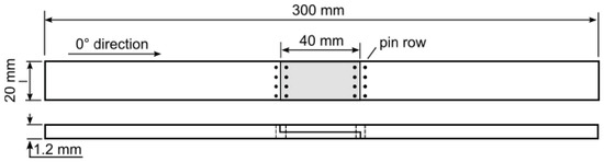
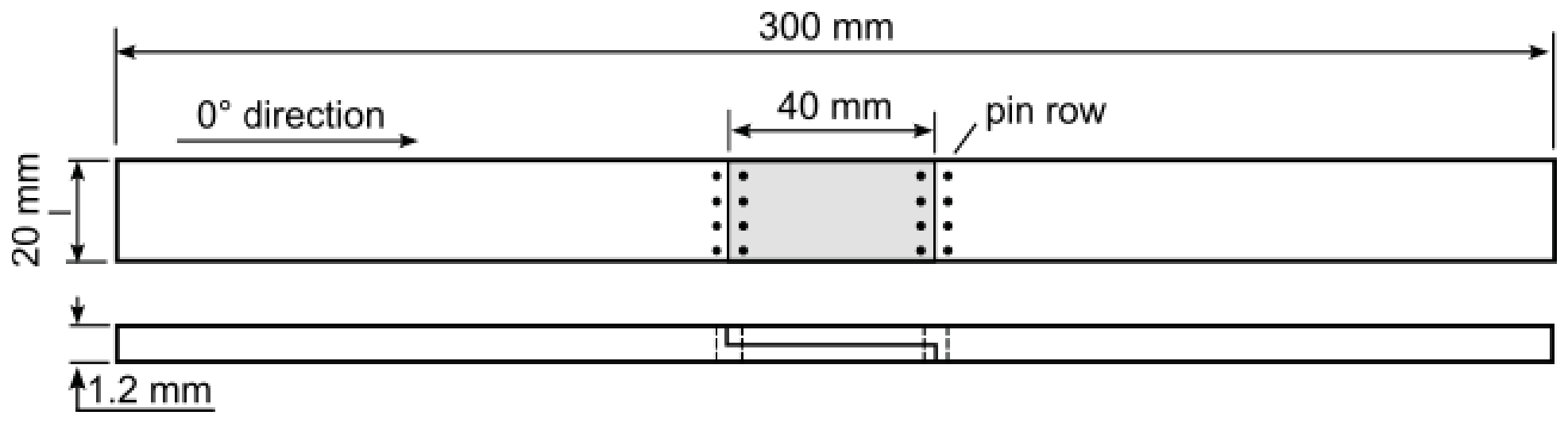
Single-step lap joints were fabricated by bonding cross-ply ([90/0]2s) laminates, manufactured from unidirectional carbon fiber/epoxy prepreg tape (HS150/ER450; CIT, Legnano, Italy). The composite adherends were joined over an overlap length of 40 mm at the mid-plane 0°/0° interface without interposing any additional adhesive layer. Before curing, some panels were selectively reinforced in the thickness direction with stainless steel pins, produced from a continuous wire of 0.5 mm diameter. Z-pins were manually inserted into pre-punched holes and aligned in four rows symmetrically arranged in pairs straddling the joint line (Figure 1). Each row of z-pins was inserted at 5 mm from the joint edge, while the spacing between adjacent pins was set at 5 mm. Thus, the resulting pin areal density on the overlap region was approximately 0.4%. After z-pinning, the joint panels were vacuum bagged and subsequently consolidated in autoclave for 2 h under a pressure of 6 bar and a curing temperature of 135 °C.
Figure 1.
Schematic of the considered sample.
Uniaxial tensile tests were conducted using a 250 kN Instron servo-electric testing machine operating in displacement-controlled mode, with a crosshead speed of 1 mm/min. During testing, the applied load and the longitudinal strain of the joined region were continuously monitored to assess the stiffness degradation of the tested samples associated with the initiation and propagation of damage. The longitudinal strain was measured with an extensometer with a gauge length of 62.5 mm.
3. Finite Element Model
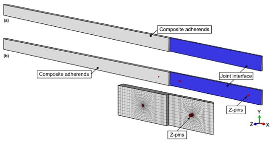
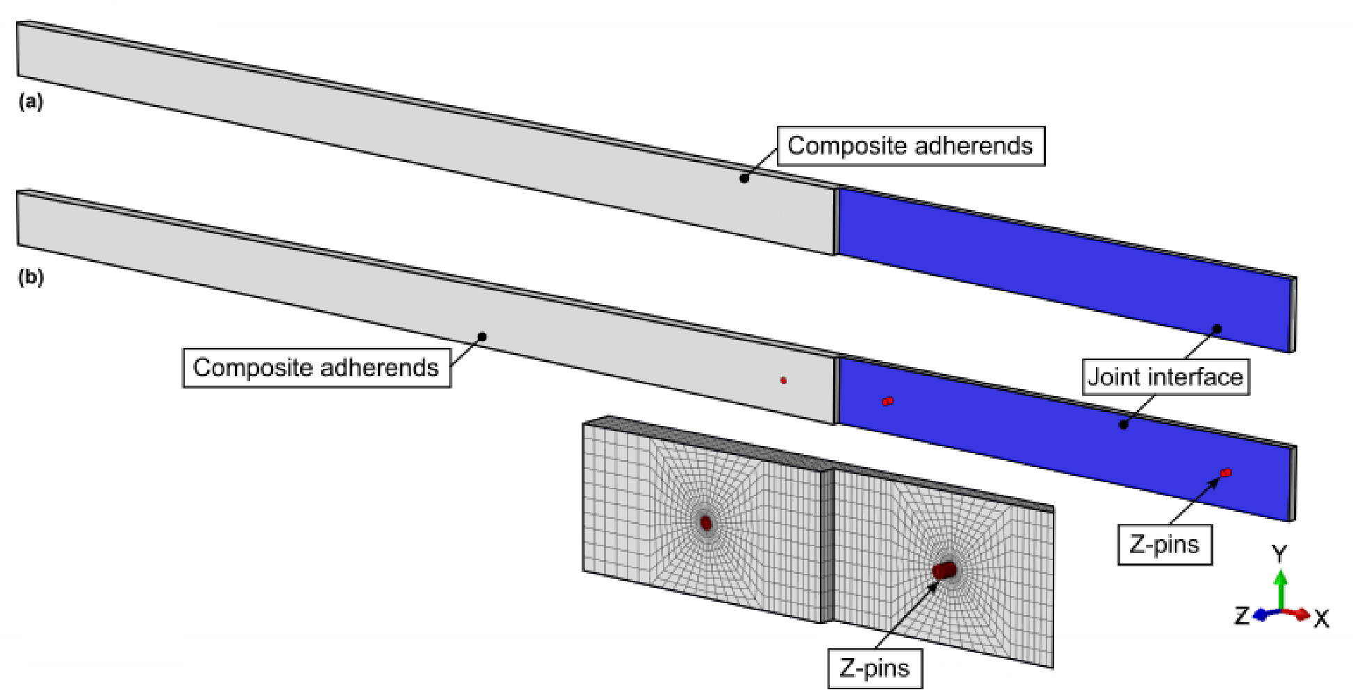
In order to investigate the mechanical response of the joints, a three-dimensional finite element (FE) model was developed using the commercial solver ABAQUS/Explicit. Figure 2 illustrates the FE model of both the pinned and unpinned configurations. The composite adherends and metallic z-pins were discretized using 8-node linear brick elements with reduced integration (C3D8R). Each ply of the laminate was modeled with a single element, resulting in 8 elements through the laminate thickness. The mechanical behavior of the composite plies was assumed to be linear elastic, while the z-pins were modeled using an elasto-plastic constitutive law incorporating isotropic hardening. The main material properties of both composite adherends and metallic z-pins were experimentally evaluated and summarized in Table 1.
Figure 2.
FE model of the (a) unpinned and (b) z-pinned joint. For clarity, only the bottom portion of the joint is shown.
Table 1.
Main material properties used in the FE analyses.
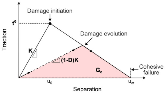
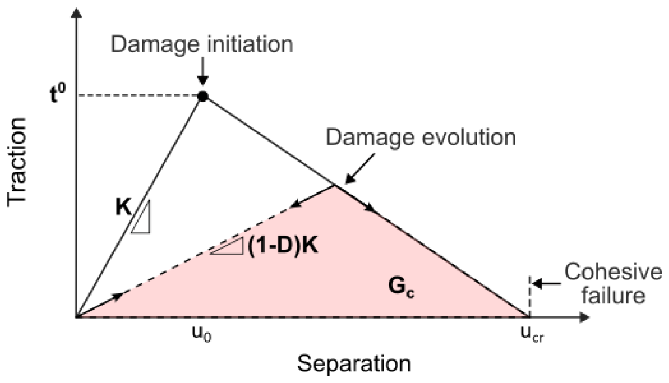
The behavior of the bonding interface between the adherends was modeled with a cohesive contact interaction governed by a bilinear traction–separation law, as depicted in Figure 3. This constitutive model comprises an initial linear elastic regime up to damage initiation. The initial stiffness, defined as a penalty stiffness parameter, enforces an elastic connection between opposing surfaces prior to damage onset, according to the following equation:
where is the nominal traction vector with components representing normal () and shear tractions (, ), is the cohesive stiffness matrix with components , , along the respective directions, and the relative displacement.
Figure 3.
Cohesive law.
Damage initiates when the stress components in the normal and shear directions reach a critical value, according to the quadratic stress interaction criterion expressed as:
where , , and are the strength of the bond when the separation is either purely normal to the interface or purely in the first or second shear direction, respectively.
Once damage initiates, the stiffness of the cohesive interface is progressively degraded according to the traction-separation law. The degradation of cohesive stiffness is modeled using a scalar damage variable , which increases monotonically from 0 (undamaged material) to 1 (complete failure) as damage accumulates. The degraded traction–separation relationship is expressed as:
The evolution of damage is governed by an energy-based approach, in which the fracture energy dissipated during the surface separation determines the progression of the scalar damage variable. The fracture energy values in pure opening () and pure shear ( and ) were experimentally obtained by performing Double Cantilever Beam (DCB) and End Notch Flexure (ENF) tests in accordance with ASTM standards [30,31], and are summarized in Table 1. To account for mixed-mode loading, the Benzeggagh–Kenane criterion is applied, which defines the effective critical fracture energy as a function of the fracture mode mixity:
where , , and are the opening and shear energy release rates, and is the Benzeggagh–Kenane parameter, whose value was set to 2.28 according to [32,33,34]. Therefore, as the damage variable increases, the energy release rate accumulates. When the accumulated energy equals the critical mixed-mode fracture energy , cohesive traction vanishes and complete decohesion occurs.
The pin–laminate interface was modeled as a cohesive contact interface. The response of this interface was described using a traction–separation law, whose parameters were set equal to those adopted to model the behavior of the joining interface between composite adherends.
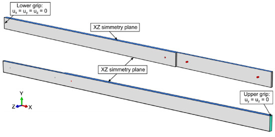
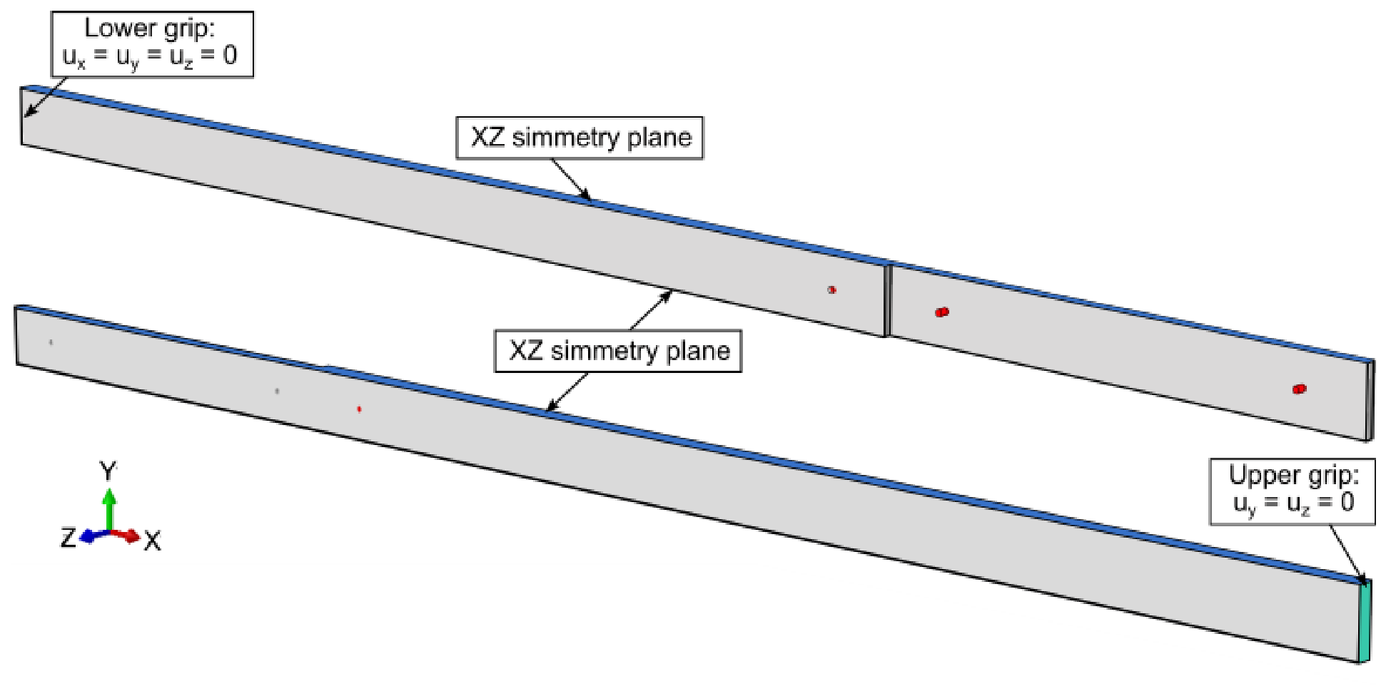
Boundary conditions were applied to the surfaces of the joined samples, as depicted in Figure 4. One end of the joint was constrained by fixing one lateral face, while a displacement was imposed in the x-direction at the opposite end to simulate the movement of the testing machine’s moving head. To reduce computational costs, a model representing a 5 mm strip of the sample was employed, with symmetry boundary conditions imposed on the XZ planes, as shown in Figure 4.
Figure 4.
FE model of boundary conditions.
4. Results and Discussion
The capability of the FE model to capture the effect of selective z-pinning on the structural response of the step-lap composite joints was assessed by comparing the results of the numerical simulations with experimental observations made during tensile tests and subsequent damage analyses. The comparison was made in terms of load–strain curves and the growth of crack length with loading as recorded during the experimental tests.
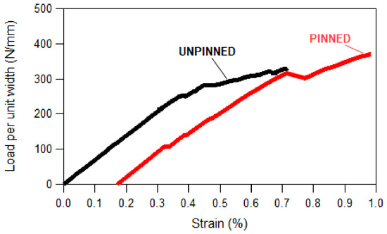
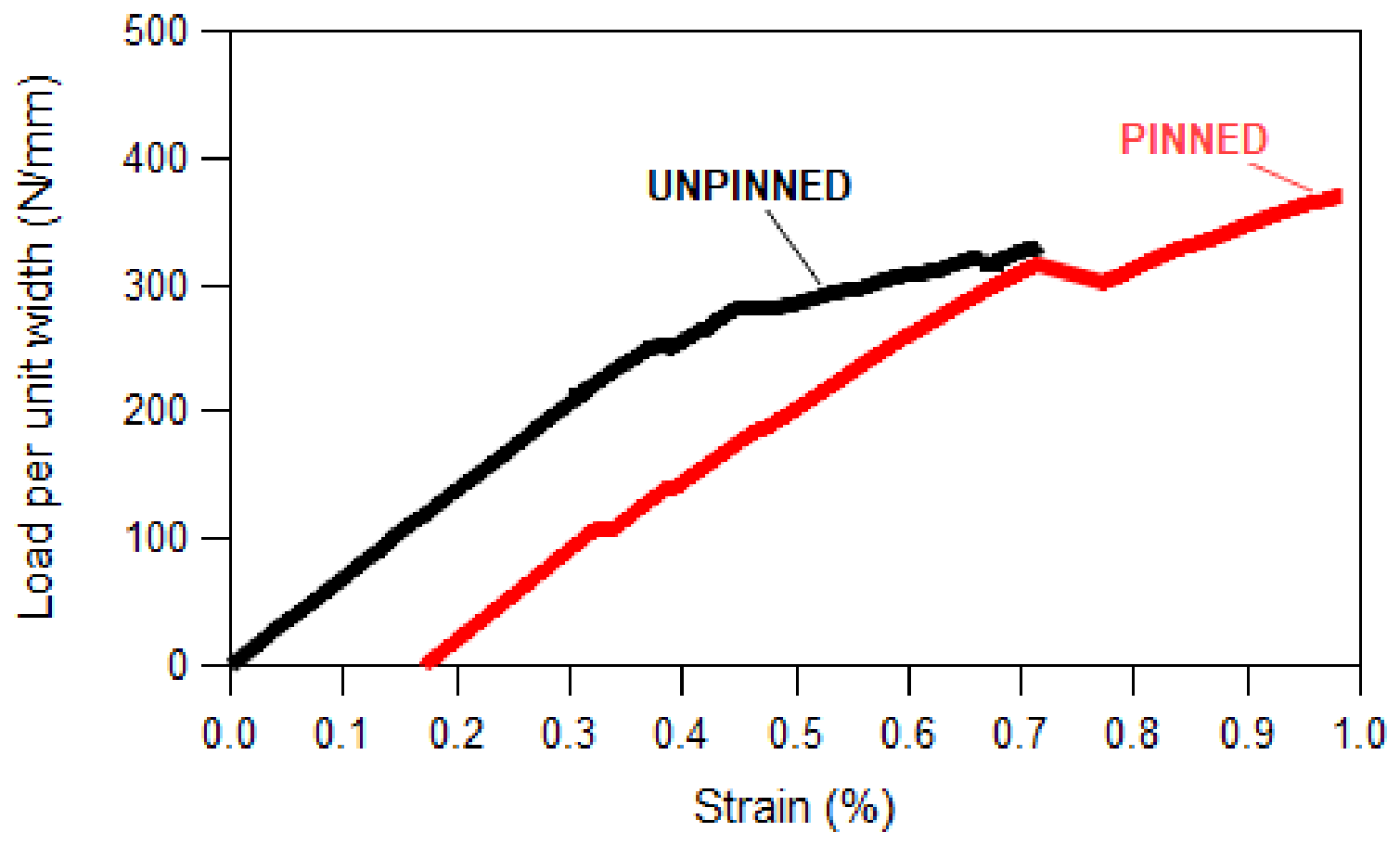
Figure 5 presents a typical load (per unit width)–strain curve of unpinned and z-pinned step-lap joints recorded during the performed quasi-static tensile test. Both unpinned and pinned joints exhibit a load–strain curve consisting of an initial linear region up to approximately 250 N/mm, followed by a nonlinear region in which the stiffness progressively degrades due to the initiation and subsequent growth of interfacial delamination (debonding). Nonetheless, the presence of through-thickness reinforcement induces an increase of approximately 15% in the joint ultimate tensile strength. It is also worth noting that unpinned and pinned specimens exhibit comparable stiffness. This evidence indicates that the introduction of z-pins may effectively enhance the load-carrying capacity of the joint, even at a very low areal density and, thus, without compromising the overall joint stiffness.
Figure 5.
Load (per unit width) vs. strain of unpinned and z-pinned joints under static load. The curve of the pinned joint has been shifted for clarity.
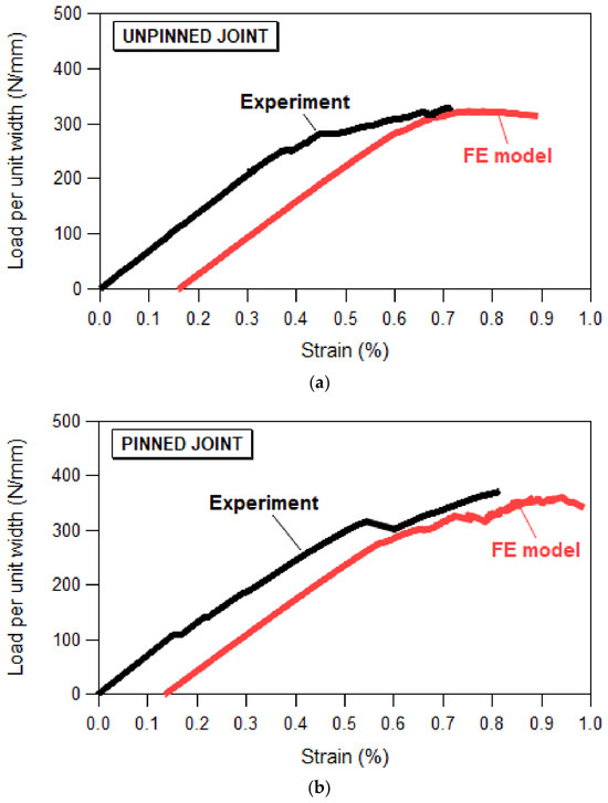
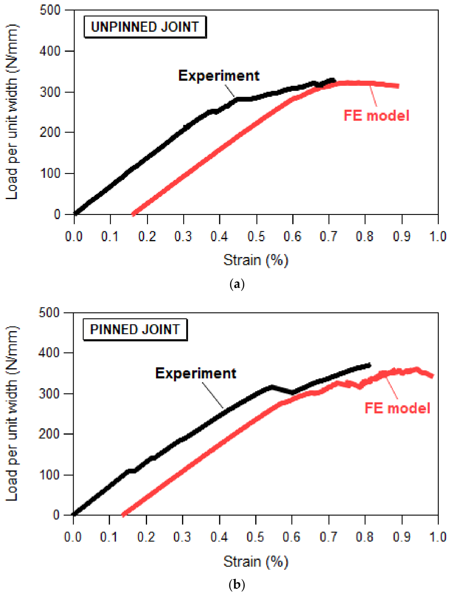
Moreover, z-pinned joints exhibit an extended strain-to-failure range, showing improved damage tolerance and enhanced energy absorption prior to failure. Figure 6 compares the experimental load–strain responses (black curves) with the corresponding numerical predictions (red curves) for both unpinned (Figure 6a) and z-pinned (Figure 6b) joints. The relatively good correlation between experimental and numerical results indicates the model’s ability to capture the mechanical behavior of the joints. In particular, the model provides a reliable estimation of the increase in static strength due to z-pin insertion.
Figure 6.
Comparison of experimental and predicted load-strain curves for unpinned (a) and z- pinned (b) samples. The numerical curves have been shifted for clarity.
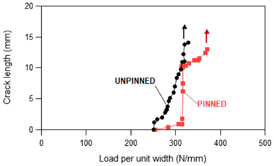
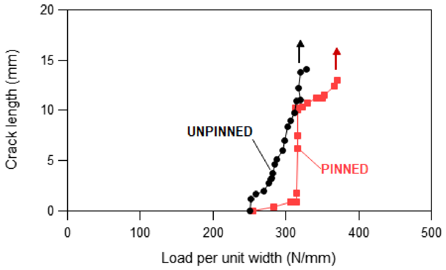
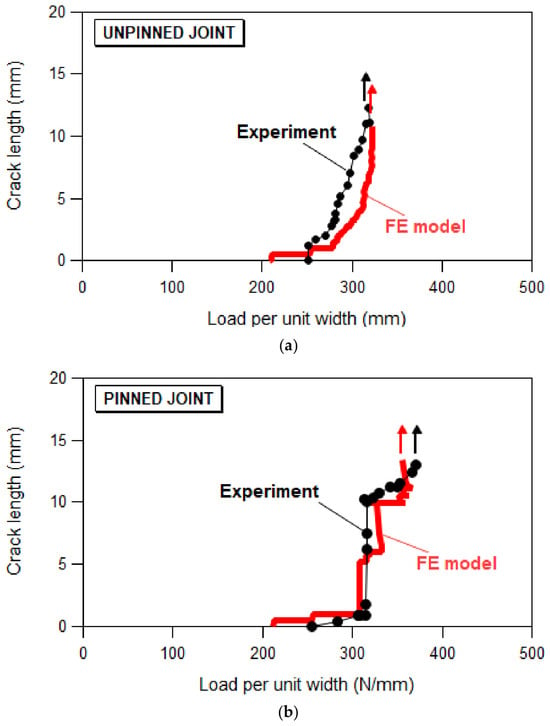
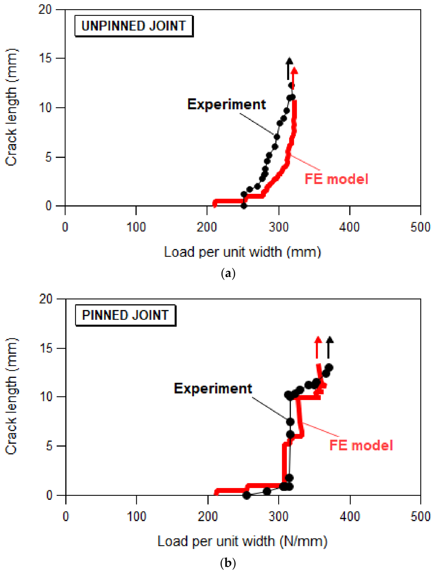
The effect of z-pins on the damage resistance of single step-lap joints was assessed by analyzing the growth of the debonding crack as a function of the applied load. Figure 7 shows the debonding crack length as a function of the applied load for both unpinned and pinned joints.
Figure 7.
Debonding crack length vs. load (per unit width) of unpinned and z-pinned samples. Arrows indicate unstable crack propagation.
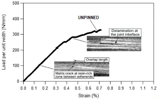
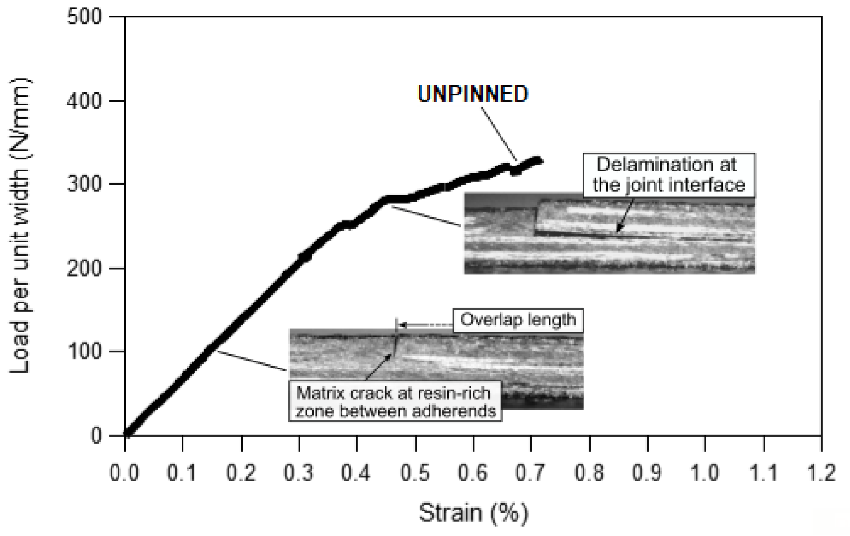
For unpinned specimens, direct observation of the joint side surfaces during testing reveals that damage initiation is characterized by the formation of small matrix cracks in the resin-rich regions located at the edges of the overlap zone (Figure 8). The onset of these matrix cracks, which corresponds to small irregularities in the otherwise linear load–strain curves (Figure 5), triggers the onset of short interfacial delaminations. As loading progresses, these delaminations coalesce and propagate along the joining interface, eventually leading to complete debonding of the adherends. Once a critical load threshold is reached, crack propagation becomes unstable, resulting in sudden and full separation of the joint adherends. A similar sequence of events is also observed in z-pinned joints, although the reinforcing effect of the z-pins clearly restrains the growth of debonding as compared to unpinned joints.
Figure 8.
Damage evolution in unpinned samples.
We may see that in unpinned joints, the debonding crack grows at a steadily increasing rate with rising load, before becoming unstable, resulting in the complete failure of the joint. In pinned joints, however, the growth of the crack occurs in sequential stages, associated with different ranges of applied loads and crack lengths. Initially, short debonding cracks grow progressively as the load rises, although at a reduced rate compared to unpinned joints, due to the beneficial effect of z-pins on the stress distribution at the overlap edges. Upon reaching a critical load, the debonding crack becomes unstable and quickly propagates up to the z-pin row, thereby enabling the bridging effect of z-pins. From this point onward, the z-pins start carrying the load across the debonded adherends, thus resisting crack sliding and opening, greatly slowing down crack growth until, with further increases in load, the crack becomes unstable once more, leading to final collapse.
As shown in Figure 9, the FE model correctly captures the differing trends of damage evolution in the two classes of joints and is capable of successfully reproducing the role of z-pins in controlling the successive stages of debonding growth at increasing crack lengths and load levels.
Figure 9.
Comparison of experimental and predicted debonding crack length vs. load (per unit width) curves for unpinned (a) and z-pinned (b) samples. Arrows indicate unstable crack propagation.
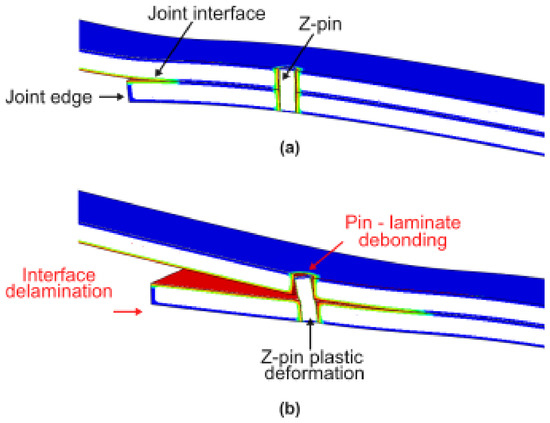
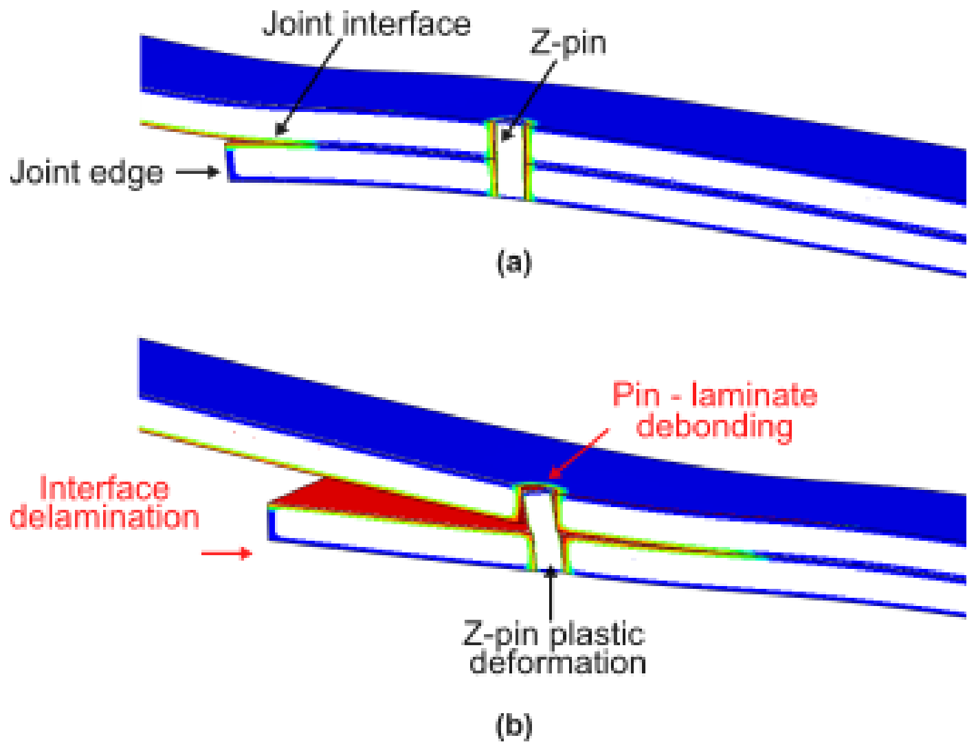
In addition to the load transfer provided by Z-pins across the debonded interface, other toughening mechanisms—such as pin/matrix debonding, pin pull-out, and pin plastic deformation (Figure 10)—also come into play, contributing to the absorption of strain energy, restraining crack growth, and delaying final failure, thus significantly enhancing the load-bearing performance of Z-pinned joints.
Figure 10.
FE images of the joint edge at short (a) and long (b) debonding cracks, highlighting energy-absorbing mechanisms such as pin-laminate debonding, pin pull-out, and pin plastic deformation.
5. Conclusions
This study investigated the structural response of selectively reinforced step-lap composite joints when subjected to a quasi-static tensile load. In order to assess the effectiveness of selective z-pinning in improving joint strength and damage tolerance, a three-dimensional FE model was developed and validated by comparing numerical results and experimental data, including force–strain response and delamination crack growth observed during testing.
The main indications arising from the present investigation are summarized below:
- The tensile response of step-lap z-pinned joints is characterized by an approximately 15% increase in strength and similar initial stiffness compared to those of analogous unpinned joints. This indicates that very low pin densities are capable of enhancing the load-carrying capacity of the joints without adversely affecting their in-plane stiffness.
- Experimental results further reveal that Z-pinned joints exhibit improved strain-to-failure properties, demonstrating enhanced energy absorption and damage tolerance.
- In both unpinned and pinned joints, damage initiates as matrix cracks in the resin-rich gaps at the overlap edges. These cracks promote the onset of delaminations at the joint interface, which, under increasing load, coalesce and propagate until the complete separation of the adherends. The presence of z-pins delays the rate of delamination growth, thereby increasing the joint’s ability to withstand higher loads over wider strain ranges.
- The numerical results are in good agreement with the experimental data, showing the effectiveness of the model in capturing the global effect of the various toughening mechanisms (pin bridging, pin/matrix debonding, pin pull-out and plastic deformation) that control the initiation and propagation of the debonding crack.
Author Contributions
Conceptualization, G.L. and F.A.; investigation, G.L., G.M., and F.A.; writing—original draft preparation, G.L., G.M., and F.A.; writing—review and editing, G.L. and F.A. All authors have read and agreed to the published version of the manuscript.
Funding
This research has been developed within the framework of the project eINS- Ecosystem of Innovation for Next Generation Sardinia (cod. ECS 00000038) funded by the Italian Ministry for Research and Education (MUR) under the National Recovery and Resilience Plan (PNRR)—MISSION 4 COMPONENT 2, “From research to business” INVESTMENT 1.5, “Creation and strengthening of Ecosystems of innovation” and construction of “Territorial R&D Leaders”.
Institutional Review Board Statement
Not applicable.
Informed Consent Statement
Not applicable.
Data Availability Statement
The data presented in the paper are available upon request.
Conflicts of Interest
The authors declare no conflicts of interest.
References
- Banea, M.D.; da Silva, L.F.M. Adhesively Bonded Joints in Composite Materials: An Overview. Proc. Inst. Mech. Eng. Part L J. Mater. Des. Appl. 2009, 223, 1–18. [Google Scholar] [CrossRef] [Scilit]
- Thoppul, S.D.; Finegan, J.; Gibson, R.F. Mechanics of Mechanically Fastened Joints in Polymer–Matrix Composite Structures—A Review. Compos. Sci. Technol. 2009, 69, 301–329. [Google Scholar] [CrossRef] [Scilit]
- Budhe, S.; Banea, M.D.; de Barros, S.; da Silva, L.F.M. An Updated Review of Adhesively Bonded Joints in Composite Materials. Int. J. Adhes. Adhes. 2017, 72, 30–42. [Google Scholar] [CrossRef] [Scilit]
- Wisnom, M.R. The Role of Delamination in Failure of Fibre-Reinforced Composites. Philos. Trans. R. Soc. A Math. Phys. Eng. Sci. 2012, 370, 1850–1870. [Google Scholar] [CrossRef] [Scilit] [PubMed]
- Shang, X.; Marques, E.A.S.; Machado, J.J.M.; Carbas, R.J.C.; Jiang, D.; da Silva, L.F.M. Review on Techniques to Improve the Strength of Adhesive Joints with Composite Adherends. Compos. Part B Eng. 2019, 177, 107363. [Google Scholar] [CrossRef] [Scilit]
- Huang, T.; Bobyr, M. A Review of Delamination Damage of Composite Materials. J. Compos. Sci. 2023, 7, 468. [Google Scholar] [CrossRef] [Scilit]
- Kinloch, A.J.; Lau, C.C.; Williams, J.G. The Peeling of Flexible Laminates. Int. J. Fract. 1994, 66, 45–70. [Google Scholar] [CrossRef] [Scilit]
- Tang, J.H.; Sridhar, I.; Srikanth, N. Static and Fatigue Failure Analysis of Adhesively Bonded Thick Composite Single Lap Joints. Compos. Sci. Technol. 2013, 86, 18–25. [Google Scholar] [CrossRef] [Scilit]
- Sayman, O.; Arikan, V.; Dogan, A.; Soykok, I.F.; Dogan, T. Failure Analysis of Adhesively Bonded Composite Joints under Transverse Impact and Different Temperatures. Compos. Part B Eng. 2013, 54, 409–414. [Google Scholar] [CrossRef] [Scilit]
- Cartié, D.D.R.; Dell’Anno, G.; Poulin, E.; Partridge, I.K. 3D Reinforcement of Stiffener-to-Skin T-Joints by Z-Pinning and Tufting. Eng. Fract. Mech. 2006, 73, 2532–2540. [Google Scholar] [CrossRef] [Scilit]
- Bogdanovich, A.E.; Dannemann, M.; Döll, J.; Leschik, T.; Singletary, J.N.; Hufenbach, W.A. Experimental Study of Joining Thick Composites Reinforced with Non-Crimp 3D Orthogonal Woven E-Glass Fabrics. Compos. Part A Appl. Sci. Manuf. 2011, 42, 896–905. [Google Scholar] [CrossRef] [Scilit]
- Aymerich, F. Effect of Stitching on the Static and Fatigue Performance of Co-Cured Composite Single-Lap Joints. J. Compos. Mater. 2004, 38, 243–257. [Google Scholar] [CrossRef] [Scilit]
- Aymerich, F.; Onnis, R.; Priolo, P. Analysis of the Effect of Stitching on the Fatigue Strength of Single-Lap Composite Joints. Compos. Sci. Technol. 2006, 66, 166–175. [Google Scholar] [CrossRef] [Scilit]
- Koh, T.M.; Isa, M.D.; Feih, S.; Mouritz, A.P. Experimental Assessment of the Damage Tolerance of Z-Pinned T-Stiffened Composite Panels. Compos. Part B Eng. 2013, 44, 620–627. [Google Scholar] [CrossRef] [Scilit]
- Francesconi, L.; Aymerich, F. Effect of Z-Pinning on the Impact Resistance of Composite Laminates with Different Layups. Compos. Part A Appl. Sci. Manuf. 2018, 114, 136–148. [Google Scholar] [CrossRef] [Scilit]
- Chang, P.; Mouritz, A.P.; Cox, B.N. Properties and Failure Mechanisms of Pinned Composite Lap Joints in Monotonic and Cyclic Tension. Compos. Sci. Technol. 2006, 66, 2163–2176. [Google Scholar] [CrossRef] [Scilit]
- Koh, T.M.; Feih, S.; Mouritz, A.P. Strengthening Mechanics of Thin and Thick Composite T-Joints Reinforced with z-Pins. Compos. Part A Appl. Sci. Manuf. 2012, 43, 1308–1317. [Google Scholar] [CrossRef] [Scilit]
- Loi, G.; Buonadonna, P.; El Mohtadi, R.; Carta, M.; Lai, D.; El Mehtedi, M.; Aymerich, F. Effect of Selective Z-Pinning on the Static and Fatigue Strength of Step Joints between Composite Adherends. J. Compos. Sci. 2024, 8, 84. [Google Scholar] [CrossRef] [Scilit]
- Mouritz, A.P. Review of Z-Pinned Composite Laminates. Compos. Part A Appl. Sci. Manuf. 2007, 38, 2383–2397. [Google Scholar] [CrossRef] [Scilit]
- Sarantinos, N.; Tsantzalis, S.; Ucsnik, S.; Kostopoulos, V. Review of Through-the-Thickness Reinforced Composites in Joints. Compos. Struct. 2019, 229, 111404. [Google Scholar] [CrossRef] [Scilit]
- Mouritz, A.P. Review of Z-Pinned Laminates and Sandwich Composites. Compos. Part A Appl. Sci. Manuf. 2020, 139, 106128. [Google Scholar] [CrossRef] [Scilit]
- Kostopoulos, V.; Sarantinos, N.; Tsantzalis, S. Review of Through-the-Thickness Reinforced z-Pinned Composites. J. Compos. Sci. 2020, 4, 31. [Google Scholar] [CrossRef] [Scilit]
- Cartié, D.D.R.; Cox, B.N.; Fleck, N.A. Mechanisms of Crack Bridging by Composite and Metallic Rods. Compos. Part A Appl. Sci. Manuf. 2004, 35, 1325–1336. [Google Scholar] [CrossRef] [Scilit]
- Ravindran, A.R.; Ladani, R.B.; Wang, C.H.; Mouritz, A.P. Design Considerations in the Strengthening of Composite Lap Joints Using Metal Z-Pins. Compos. Part A Appl. Sci. Manuf. 2022, 160, 107031. [Google Scholar] [CrossRef] [Scilit]
- Koh, T.; Isa, M.; Chang, P.; Mouritz, A. Improving the Structural Properties and Damage Tolerance of Bonded Composite Joints Using Z-Pins. J. Compos. Mater. 2012, 46, 3255–3265. [Google Scholar] [CrossRef] [Scilit]
- Ko, M.-G.; Kweon, J.-H.; Choi, J.-H. Fatigue Characteristics of Jagged Pin-Reinforced Composite Single-Lap Joints in Hygrothermal Environments. Compos. Struct. 2015, 119, 59–66. [Google Scholar] [CrossRef] [Scilit]
- Dhilipkumar, T.; Rajesh, M. Multi-Scale Strengthening of Co-Cure Joints through Multiwall Carbon Nanotube Modified Adhesive and GFRP Pins. Compos. Commun. 2022, 29, 101056. [Google Scholar] [CrossRef] [Scilit]
- Löbel, T.; Kolesnikov, B.; Scheffler, S.; Stahl, A.; Hühne, C. Enhanced Tensile Strength of Composite Joints by Using Staple-like Pins: Working Principles and Experimental Validation. Compos. Struct. 2013, 106, 453–460. [Google Scholar] [CrossRef] [Scilit]
- Yang, Y.; Gong, M.; Xia, X.; Wu, L. Experimental and Numerical Study on Mechanical Properties of Z-Pins Reinforced Composites Adhesively Bonded Single-Lap Joints. CMES 2022, 131, 365–378. [Google Scholar] [CrossRef] [Scilit]
- ASTM D5528-13; Standard Test Method for Mode I Interlaminar Fracture Toughness of Unidirectional Fiber-Reinforced Polymer Matrix Composites. ASTM International: West Conshohocken, PA, USA, 2022. Available online: https://store.astm.org/d5528-13.html (accessed on 20 September 2025).
- ASTM D7905/D7905M-14; Standard Test Method for Determination of the Mode II Interlaminar Fracture Toughness of Unidirectional Fiber-Reinforced Polymer Matrix Composites. ASTM International: West Conshohocken, PA, USA, 2019. Available online: https://store.astm.org/d7905_d7905m-14.html (accessed on 20 September 2025).
- Camanho, P.P.; Davila, C.G.; de Moura, M.F. Numerical Simulation of Mixed-Mode Progressive Delamination in Composite Materials. J. Compos. Mater. 2003, 37, 1415–1438. [Google Scholar] [CrossRef] [Scilit]
- Camanho, P.P.; Dávila, C.G. Mixed-Mode Decohesion Finite Elements for the Simulation of Delamination in Composite Materials; NASA/TM-2002-211737; NASA Langley Research Center: Hampton, VA, USA, 2002. [Google Scholar]
- Turon, A.; Camanho, P.P.; Costa, J.; Dávila, C.G. A Damage Model for the Simulation of Delamination in Advanced Composites under Variable-Mode Loading. Mech. Mater. 2006, 38, 1072–1089. [Google Scholar] [CrossRef] [Scilit]

Disclaimer/Publisher’s Note: The statements, opinions and data contained in all publications are solely those of the individual author(s) and contributor(s) and not of MDPI and/or the editor(s). MDPI and/or the editor(s) disclaim responsibility for any injury to people or property resulting from any ideas, methods, instructions or products referred to in the content. |
© 2026 by the authors. Licensee MDPI, Basel, Switzerland. This article is an open access article distributed under the terms and conditions of the Creative Commons Attribution (CC BY) license.