


Abstract
The paper describes the design and calibration of an innovative scaled twin-disc test rig, which enables the investigation of both the wheel–rail and wheel–shoe contact interactions. The design of the main bench components, including the load application and tread braking systems, was performed to comply with specific scaling rules, allowing for an easy correlation of data obtained on the scaled bench with the real-world scenario. The preliminary calibration of the load application system and tread braking unit proves excellent repeatability and linearity, thus confirming the robustness and validity of the bench design.
1. Introduction
Railway systems are based on tribological interactions between different body pairs. The vehicle dynamic behaviour, with running safety and stability as major concerns, is determined by the forces exchanged at the wheel–rail contact patch, which eventually depend on the conditions of the contact interface [1,2,3,4,5]. At the same time, tread braking systems, which are the most widespread solution installed on freight waggons, rely on the interaction between the wheel tread surface and brake shoes [6].
Despite being vital for the proper functioning of railway systems, these tribological interactions have downsides that should be deeply investigated to ensure the highest efficiency and reliability. The wheel–rail rolling–sliding contact is related to several degradation phenomena, including wear of the lateral profiles, which modifies the shape and location of the contact patch, with impacts on the overall vehicle dynamics [7,8,9,10,11]. The wheel–shoe sliding contact leads to the generation of high amounts of friction heat, causing thermal stresses in the wheel, with increasing concerns due to the introduction of composite shoe materials [12,13,14].
Data obtained from experimental campaigns is vital to tune and validate numerical models that can predict the behaviour of wheels, rails and shoes [15,16,17,18]. Such models can thrust the implementation of monitoring systems and algorithms [19], hence increasing the overall safety of railway systems. The investigation of the previously mentioned phenomena with on-track tests has several shortcomings, mainly due to poor repeatability and high costs. A valuable solution is the use of dedicated test benches in laboratory environments, ensuring higher repeatability of test conditions. In the railway field, twin-discs are the most widespread solution for the laboratory investigation of the wheel–rail contact, with studies on the determination of friction coefficient values and wear regimes under different contact conditions [20,21,22,23,24,25]. Nonetheless, typical twin-discs consider a simplified cylindrical geometry for the discs and do not apply a proper scaling technique. This makes it difficult to relate measured data to the real-world scenario. On the other hand, the investigation of the thermo-mechanical behaviour of tread braking systems is commonly performed using full-scale dynamometer test benches [26,27,28], complying with the prescriptions of international rules [29]. However, whilst being the best option for the certification of brake blocks and tread-braked wheels, full-scale dynamometers have certain requirements, e.g., high power demand and high cost, that make them impractical for installation within small research centres like universities. Moreover, these dynamometer benches are not able to consider the cooling effect due to the contact of the wheel with the rail while running along the track.
The present paper describes the design and calibration of a novel 1:5 scaled test bench installed in the laboratories of the railway mechanics research group at Politecnico di Torino [30,31]. Thanks to its modular design, the bench enables investigation of both the wheel–rail tribological behaviour and the wheel–shoe thermo-mechanical interaction. As a major novelty, different types of tests can be run following two different scaling techniques, thus making it possible to relate the measurements on the scaled test rig to quantities on the full-scale system. The paper structure is as follows. Section 2 shows the design of the main bench components. Section 3 shows the current bench configuration, focusing on the types of tests that can be carried out and describing the preliminary calibration of the test rig. Finally, the Section 4 provides the main outcomes of the paper and suggests future developments of the activity.
2. Design of the Scaled Twin-Disc Bench
Twin-disc benches typically include four main components that are needed to obtain contact between the two bodies and generate creepage:
- Rail disc.
- Wheel disc.
- Load the application system.
- Mechanical power supply system.
The novel scaled twin-disc bench includes all these components, although its design features innovations and upgrades with respect to traditional devices. Furthermore, the new bench can also be equipped with up to 2 modular braking units to simulate tread braking operations. The biggest benefit of the test bench, which makes it one-of-a-kind, is that it is designed to comply with specific scaling rules [32]. Therefore, it is possible to easily correlate measured data to real-world conditions. To perform wheel–rail wear tests for different values of contact pressure and slip speed, the bench is designed to adhere to Pascal’s similitude model [33]. This similitude model is the most suited for tribological tests, as it prescribes a unitary scaling for contact pressure and speed. Instead, the design of the braking units is carried out to comply with an ad hoc thermal scaling rule, specifically derived by the authors [31].
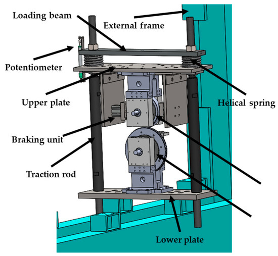
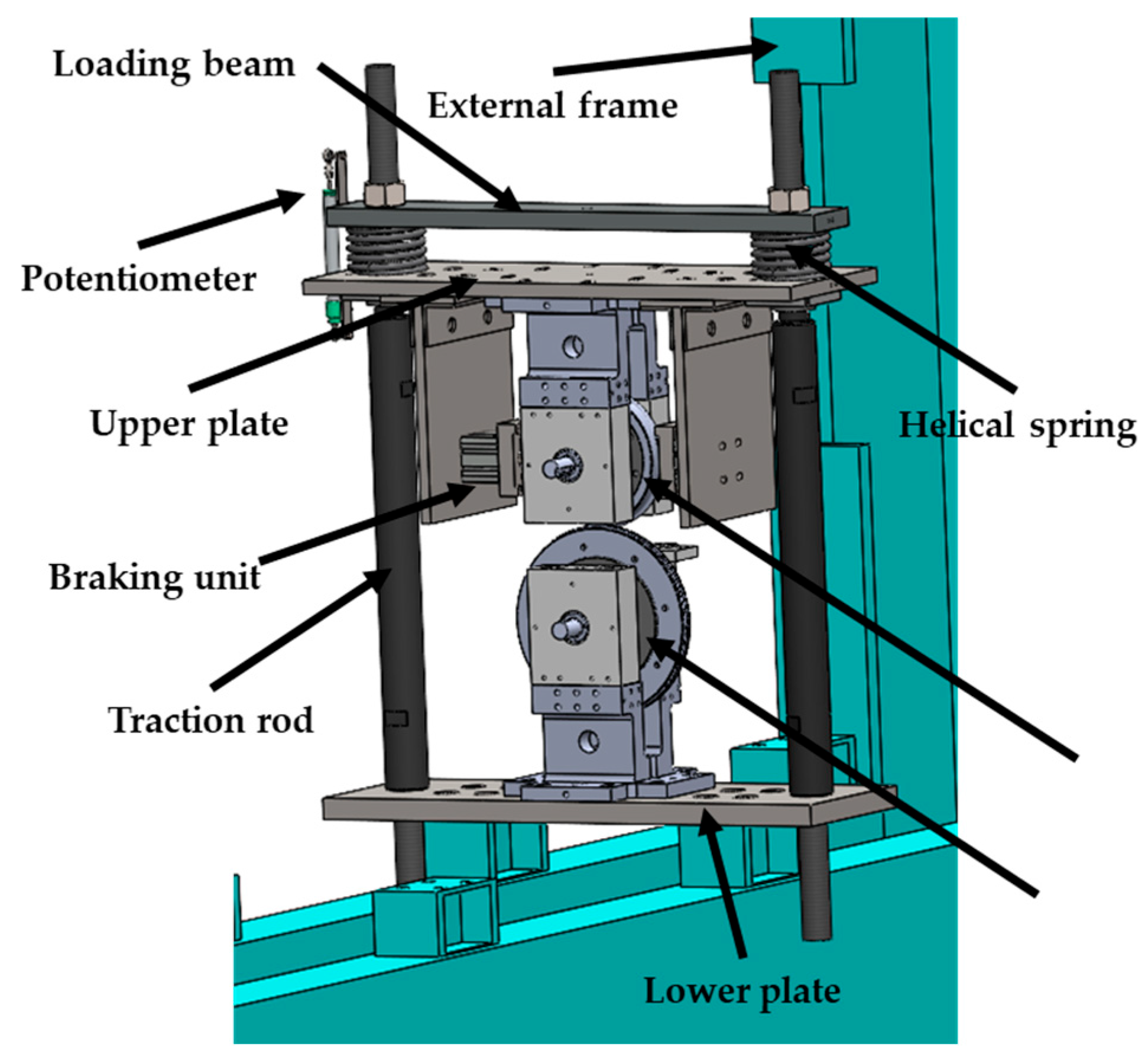
The CAD model of the bench is shown in Figure 1. The bench frame includes lower and upper plates, which are connected through threaded traction rods that increase the overall stiffness of the system. The lower plate is mounted to the external frame.
Figure 1.
CAD model of the novel scaled twin-disc test rig.
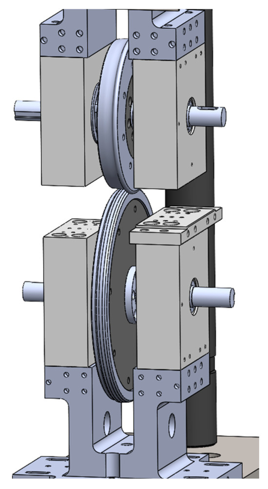
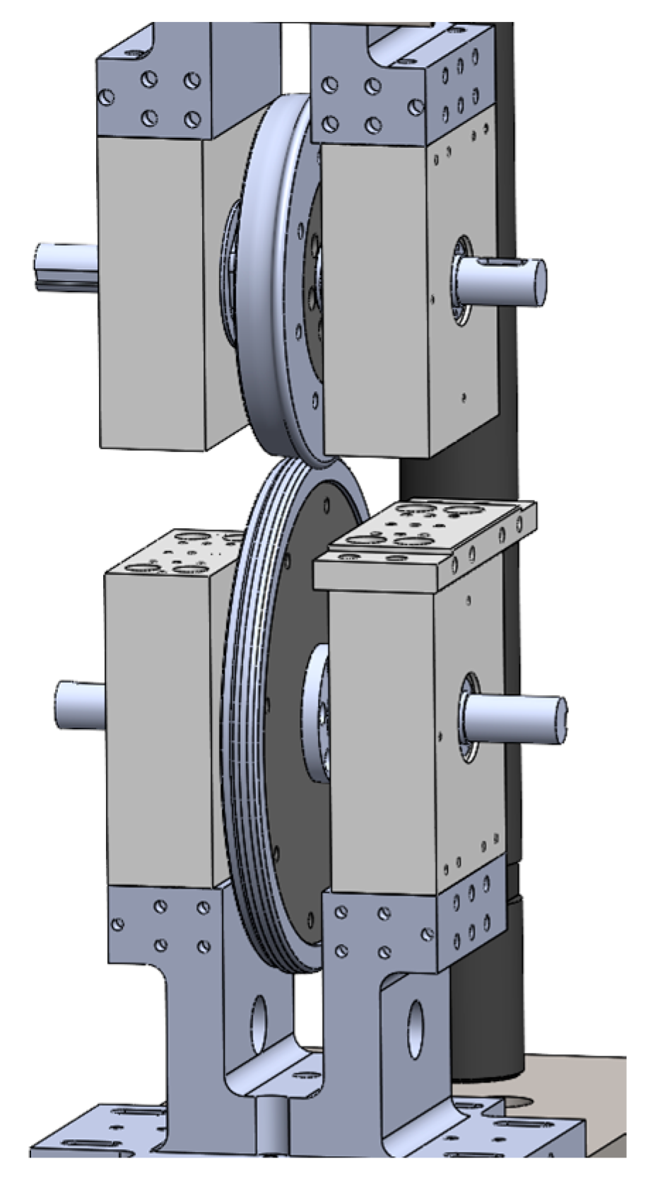
Since the bench is conceived to investigate wear, the wheel and rail discs are made of a hub and a rim; see Figure 2. As a major innovation, the rims are not cylindrical but are instead machined to 1:5 scaled wheel/rail profiles to better resemble the real contact geometry. Therefore, it is possible to test different wheel/rail materials and profiles by simply replacing the rims, with significant cost advantages. Currently, the wheel rim is machined to the scaled S1002 profile. The rail roller rim, instead, is machined to the scaled UIC 60 profile, with a minor correction on the lateral curvature at the nominal contact point to ensure a proper scaling of the contact patch area.
Figure 2.
Detail of the contact between the rail (lower) and wheel (upper) rollers. See the hub and rim of each disc and the lateral profiles.
The load application system, which is used to adjust the normal load at the contact interface between the two discs, is based on a threaded system. By tightening the bolts, a pair of helical springs is compressed between the loading beam and the bench upper plate; see Figure 1. The stiffness of the helical springs is selected to apply the target values of normal load and to minimise the preload loss when the wheel and rail profiles are worn out. According to Pascal’s similitude rule, the normal load scales by a factor equal to the square of the length scaling factor, i.e., 25 on the 1:5 scaled twin-disc test rig. Therefore, an axle-load value of 22.5 t, i.e., a wheel load of 12.5 t, which is the limit value on most European lines, corresponds to a normal load equal to 450 kg on the scaled twin-disc. Consequently, a pair of commercial helical springs with nominal stiffness of 29.87 N/mm each and free length of 150 mm is selected (SODEMANN 14830). This ensures that, if the radius of each roller is worn out by 1 mm, the preload loss corresponds to an axle-load variation far below 1 t (609 kg). The applied normal load is estimated with a linear potentiometer mounted between the loading beam and the bench upper plate.
Concerning the mechanical power system, the bench is designed to mount one brushless motor on each disc shaft, using plates that can be connected to the axle-boxes of both disc shafts. The brushless motors (ACM BRL 220, manufactured by ACM Engineering, Bardello, Italy) are refurbished from previous test benches designed by the research group [34,35], as their characteristics (maximum torque: 650 Nm, nominal torque: 150 Nm@2000 rpm, maximum continuous power: 37 kW) well suit the new application. In fact, when considering Pascal’s rule, speed on the scaled system should be the same as for the full-scale system. Knowing that the wheel and rail discs have nominal radii of 92 and 132 mm, respectively, the selected motors allow wear tests to be carried out, considering reference conditions for both passenger (80 km/h with 12 t axle-load) and freight (60 km/h with 22.5 t axle-load) vehicles.
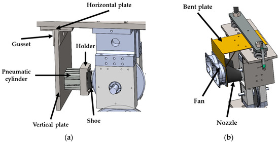
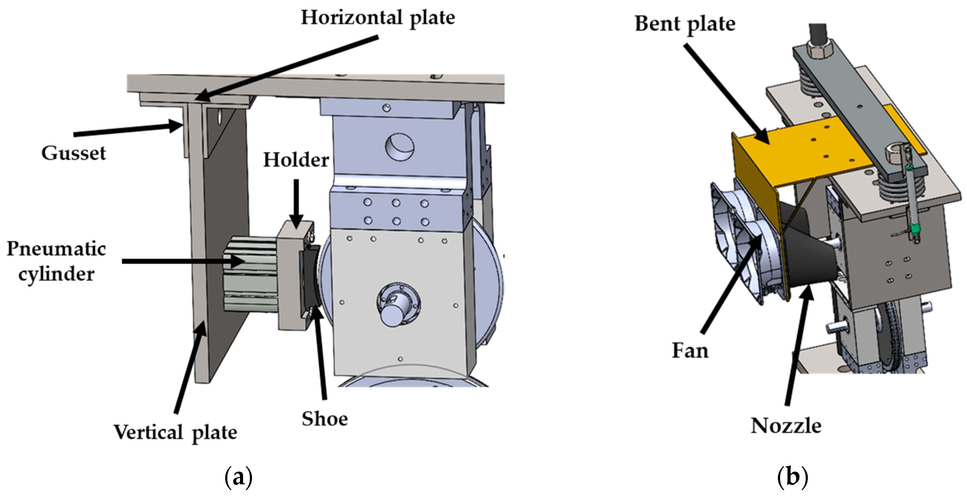
As already mentioned, one of the biggest novelties of the new scaled twin-disc rig is that it is provided with an additional scaled tread braking system, which makes it possible to perform thermal tests to experimentally determine the thermal field inside brake blocks and wheels, as well as tests to assess the wheel–shoe thermo-mechanical behaviour. The bench can be equipped with one braking unit per side, so that it is possible to investigate configurations with one or two blocks per wheel. The detail of one braking unit is shown in Figure 3a. Each braking unit is mounted to the bench frame using a horizontal plate connected to the bench upper plate. The braking effort is provided using 1:5 scaled brake shoes, cut from real-world counterparts, that are pushed against the wheel disc tread surface with a pneumatic cylinder. The latter is fixed to a vertical plate, which is tightened to the horizontal plate using a pair of gussets.
Figure 3.
CAD model of the braking system: (a) braking unit; (b) cooling system.
The pneumatic cylinder is selected based on the novel thermal scaling rule, which prescribes that the heat flux on the scaled system should be magnified by a factor equal to the size scaling factor. This can be achieved by magnifying the wheel–shoe pressing force. The pneumatic cylinder is chosen to replicate the reference drag braking operation defined in the TSI Wag European rule [36], which considers an operating speed of 70 km/h for a 22.5 t axle-load vehicle. Therefore, each braking unit is equipped with a FESTO ADN-S-50-25-I-P-A pneumatic cylinder, with air supply pressure up to 10 bar and nominal force of 1178 N at 6 bar. Considering that the contact area between the scaled wheel and shoe for a Bg configuration is 64 × 16 mm2, when the maximum air supply pressure of 10 bar is applied, the average wheel–shoe contact pressure on the scaled bench is about 1.9 MPa, which corresponds to approximately 0.4 MPa on the full-scale system according to the new thermal scaling rule. This value is very close to the maximum contact pressure value achieved in typical drag braking operations, thus allowing meaningful tests to be performed on the scaled bench. At the same time, since the Pascal’s scaling rule keeps a unitary factor for pressure, the selected commercial pneumatic cylinder is suited for tribological investigations of the wheel–shoe contact, aiming at the evaluation of the dependency of the friction coefficient on speed and pressure as well as of the amount of wear. Pressure in the pneumatic cylinder is adjusted by means of a proportional valve. The valve is controlled with an input voltage signal, and it provides an output voltage that is proportional to the feedback pressure.
Apart from the selection of the pneumatic braking unit, the design of the scaled tread braking system requires the implementation of a forced cooling system. In fact, the derived thermal scaling rule prescribes that the convection coefficient on the scaled system should be magnified by a factor equal to the length scaling coefficient. Consequently, air should be accelerated on the bench to provide the required cooling. This is achieved through a specifically conceived fan–nozzle system, shown in Figure 3b. The system relies on a main bent plate which is fixed to the bench upper plate. The vertical part of the bent plate hosts a pair of commercial fans (Orion Fans OD180APL-24H*B series, Dallas, TX, USA). The outlet of each fan is connected to a specifically designed convergent nozzle used to accelerate the air flow. From a literature correlation for the calculation of the convection coefficient [37], it is estimated that the air flow speed should be around 350 km/h on the scaled bench when replicating the reference drag braking operation defined in the TSI WAG. The geometry of the nozzle, i.e., the outlet cross-section value, is determined with well-known fluid machinery equations to obtain the target air flow speed.
3. Bench Configuration and Calibration
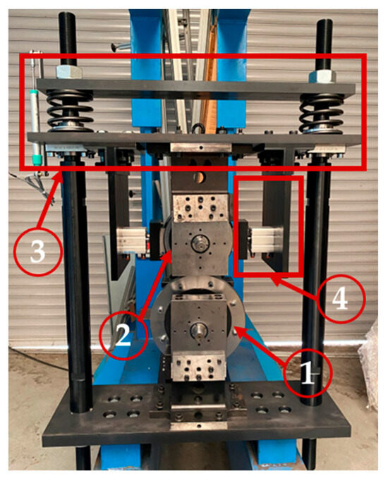
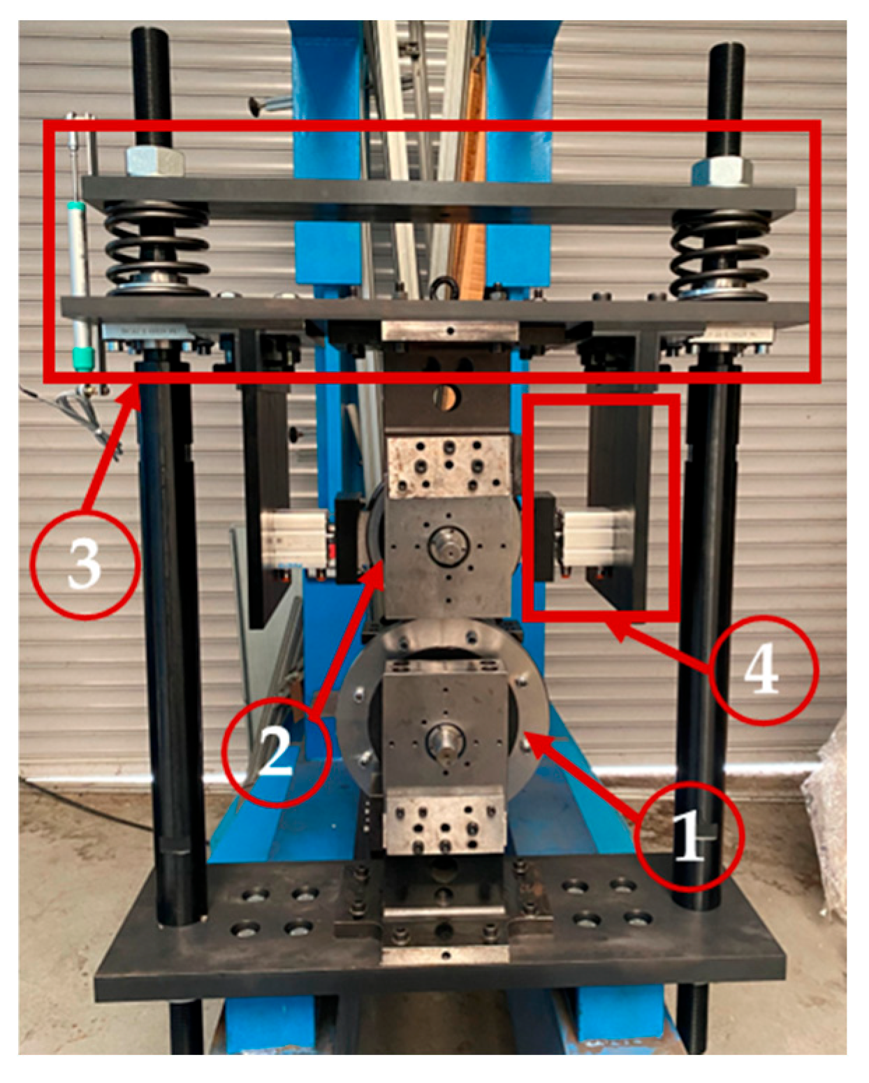
Figure 4 shows the scaled twin-disc test rig installed in the laboratories of the Politecnico di Torino railway research group. The bench is currently equipped with all its main components, except for the fan–nozzle cooling system, which is still being manufactured and assembled. Figure 4 does not show the brushless motors mounted on the bench for the sake of graphical clarity. Furthermore, the number of motors installed on the bench varies based on the type of test to be performed.
Figure 4.
The 1:5-scale twin-disc test rig. (1) Rail disc, (2) wheel disc, (3) load application system, (4) braking unit.
Essentially, the bench configuration enables the following three types of tests, managed with a dedicated LabVIEW VI routine that performs data acquisition and bench control operations.
- Tribological tests at the wheel–rail interface. This is the typical test performed on common twin-discs to obtain the values of wear and/or adhesion coefficients at the contact interface between the two discs. For this type of test, both discs are connected to independent brushless motors that control the speed in order to generate slip at the contact interface. This type of test is run in adherence with Pascal’s similitude rule, which ensures a unitary scaling of the contact pressure. This is achieved by properly setting the normal load through the load application system. When running tribological tests at the wheel–rail interface, no braking effort is applied with the scaled tread braking system.
- Tribological tests at the wheel–shoe interface. This type of test intends to assess the wear and frictional behaviour of the wheel–shoe contact. This has great relevance nowadays, as traditional cast iron shoes are being replaced with composite materials that have different frictional behaviours. These tests are run according to Pascal’s rule and hence control the proportional valve to obtain the same contact pressure at the wheel–shoe interface for the full-scale system. These tests are run with only one brushless motor, mounted on the rail disc shaft. The normal load at the wheel–rail disc contact interface is adjusted to ensure high adhesion levels between the two discs and avoid slip so that power supplied by the brushless motor on the rail disc shaft only balances the resistant torque given by the braking effort applied on the wheel disc shaft.
- Tread braking thermal tests. This kind of test aims at investigating the thermal field produced inside the wheel and brake shoes during tread braking, and measured data is used not only to compare different shoe materials but also to validate numerical models for the temperature field prediction inside wheels [38] and shoes [39,40]. These tests are again run with one motor only, connected to the rail disc shaft, whilst applying large values of normal load at the wheel–rail disc contact interface to minimise slip. The pneumatic cylinder pressure, rail roller speed and test time are adjusted to obtain heat flux and dissipated thermal energy values that comply with the specifically conceived thermal scaling rule [31], which differs from Pascal’s. Currently, preliminary thermal tests are being run that measure the thermal field with a thermal image camera, but work to install pyrometers on the bench is ongoing.
It is important to specify that due to the configuration of the twin-disc bench, when performing thermal tests, the wheel surface exchanges heat with the rail roller, which in turn tends to heat up. This differs from real-world conditions, where the tread-braked wheel is always in contact with a new and fresh part of the rails and is hence subjected to the rail chill phenomenon. Nonetheless, the rail chill effect can be considered as a local phenomenon, which would require a separate and dedicated experimental setup for proper studies. Therefore, it is believed that the new bench configuration is suited for the investigation of the thermal interaction between the wheel and shoes, as long as the interest is on the global behaviour.
As a first step before starting with an extensive experimental campaign, the bench is subjected to a first calibration stage to characterise its main components, i.e., the load application system and the tread braking unit. The calibration of the load application system aims at identifying the relationship between the potentiometer voltage and the normal load applied at the wheel–rail disc interface. The calibration of the tread braking system, instead, deals with the determination of the relationship between the proportional valve feedback pressure and the force applied by the brake cylinder. Both calibrations are performed by measuring the force of interest with a load button cell (FUTEK LLB 400 FSH 00877).
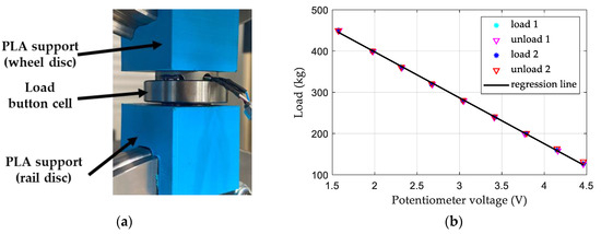
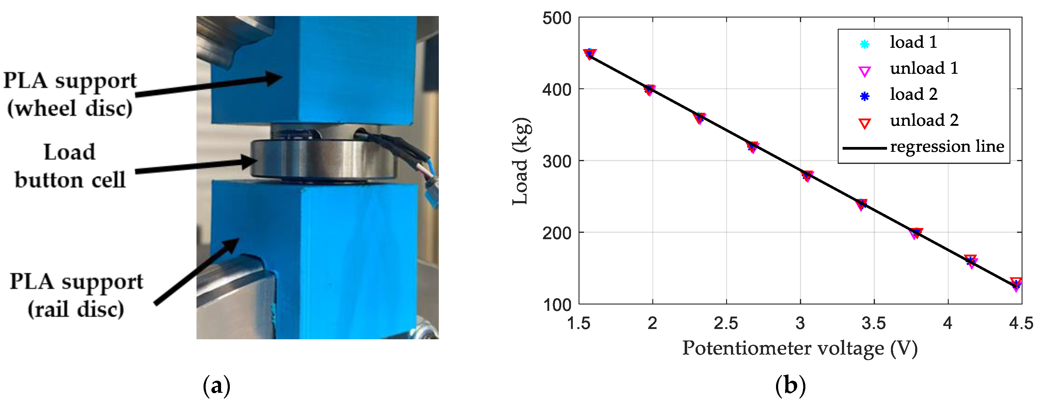
For the load application system, the load button cell is placed between two supports obtained with additive manufacturing techniques and made of polylactic acid (PLA); see Figure 5a. The supports are manufactured to resemble the negative counterparts of the wheel and rail roller profiles. The calibration of the load application system is performed by progressively tightening the bolts and then gradually reducing the applied load, exploring relevant values of full-scale axle-loads. Figure 5b shows the values recorded in two tests for the loading and unloading stages, together with the regression line. Figure 5b highlights the good repeatability of the load application system as well as its linearity, which is further proven by the values of the R2 score (0.999) and RMSE (2.51 kg) of the regression line.
Figure 5.
Calibration of the load application system: (a) positioning of the load button cell between PLA supports; (b) measured data with a regression curve.
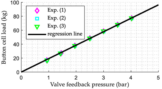
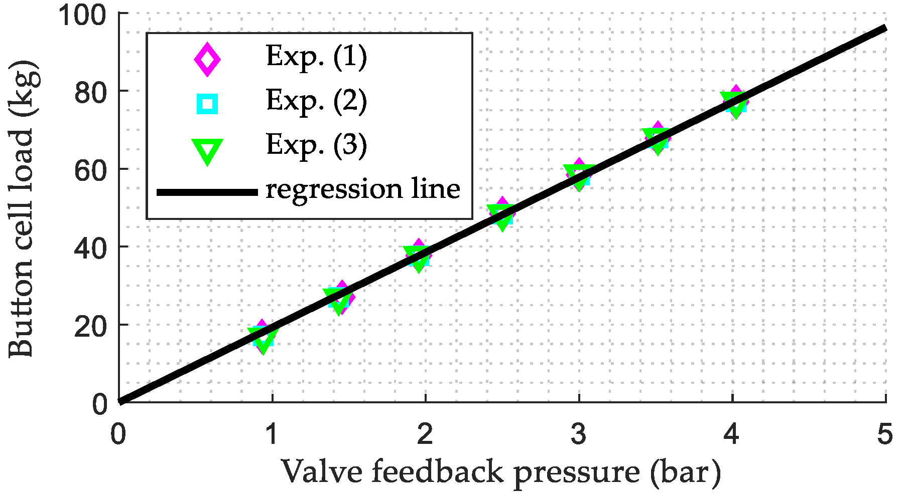
Shifting focus to the calibration of the brake cylinder, it is performed by progressively increasing the input voltage to the proportional valve and then registering the valve feedback pressure and the load measured by the load button cell. The valve feedback pressure is estimated from the valve calibration law. At the current stage of the activity, only pressure values up to 4 bar are tested, as preliminary thermal tests will be carried out with low values of braking pressure to mitigate the risks of overheating the wheel disc and scaled shoes. Figure 6 shows the results of the calibration and the experimental values recorded in three tests, highlighting the strong repeatability of the system as well as the excellent linearity and accuracy of the calibration law. In fact, the regression line is characterised by an R2 score above 0.99 and by an RMSE of 0.6 kg.
Figure 6.
Calibration of the tread braking unit.
4. Conclusions
The main outcomes of the paper are presented in the following bulleted list.
- As an upgrade to typical benches, the novel scaled twin-disc rig can be equipped with scaled modular tread braking units, thus improving and extending its testing capabilities.
- The helical springs of the load application system are selected to ensure limited loss of normal contact even after the profiles are significantly worn out, hence contributing to the repeatability and robustness of the bench. The load application system is designed to comply with Pascal’s similitude rule, allowing to simulate axle-load values up to the limit values for European vehicles.
- The selection of the pneumatic cylinder and the design of the fan–nozzle system used in the tread braking system are made to comply with a novel thermal scaling rule. This ensures that the thermal field in the scaled wheel and shoes corresponds to the thermal field on the full-scale system. The selected pneumatic cylinder allows reproducing common drag braking operations on the scaled test rig.
- The calibration of the load application system proves that good linearity exists between the potentiometer voltage output and the normal load, making it possible to estimate the applied normal load with high reliability in the planned future stages of experimental campaigns.
- The calibration law obtained for the tread braking unit allows estimation of the applied normal force from the proportional valve feedback pressure with high linearity.
Ongoing activities are dealing with experimental campaigns to evaluate the tribological and thermal behaviour of cast iron and commercial composite shoes.
Author Contributions
Conceptualisation, N.B., A.G. and N.Z.; methodology, N.B., A.G. and N.Z.; validation, N.B. and N.Z.; formal analysis, M.M. and R.P.; investigation, M.M., R.P. and N.Z.; data curation, M.M. and R.P.; writing—original draft preparation, M.M. and R.P.; writing—review and editing, N.Z.; supervision, N.B., A.G. and N.Z.; project administration, N.Z.; funding acquisition, N.Z. All authors have read and agreed to the published version of the manuscript.
Funding
This research was funded by the Ministero dell’Università e della Ricerca (MUR), grant number FISA-2023-00314.
Institutional Review Board Statement
Not applicable.
Informed Consent Statement
Not applicable.
Data Availability Statement
The raw data supporting the conclusions of this article will be made available by the authors upon request.
Conflicts of Interest
The authors declare no conflicts of interest.
References
- Polach, O. Creep forces in simulations of traction vehicles running on adhesion limit. Wear 2005, 258, 992–1000. [Google Scholar] [CrossRef] [Scilit]
- Olofsson, U.; Lewis, R.; Harmon, M. Tribology of the Wheel-Rail Contact. In Handbook of Railway Vehicle Dynamics, 2nd ed.; Iwnicki, S., Spiryagin, M., Cole, C., McSweeney, T., Eds.; CRC Press: Boca Raton, FL, USA, 2019; pp. 281–305. [Google Scholar]
- Zhai, W. Vehicle–Track Coupled Dynamics—Theory and Applications; Springer: Singapore, 2020. [Google Scholar]
- Lewis, R.; Olofsson, U. Basic tribology of the wheel-rail contact. In Wheel–Rail Interface Handbook; Lewis, R., Olofsson, U., Eds.; Woodhead Publishing: Cambridge, UK, 2009; pp. 34–57. [Google Scholar]
- Lewis, S.R.; Dwyer-Joyce, R.S. 14—Effect of contaminants on wear, fatigue and traction. In Wheel–Rail Interface Handbook; Lewis, R., Olofsson, U., Eds.; Woodhead Publishing: Cambridge, UK, 2009; pp. 437–455. [Google Scholar]
- Günay, M.; Korkmaz, M.E.; Özmen, R. An investigation on braking systems used in railway vehicles. Eng. Sci. Technol. Int. J. 2020, 23, 421–431. [Google Scholar] [CrossRef] [Scilit]
- Tunna, J.; Sinclair, J.; Perez, J. A Review of wheel wear and rolling contact fatigue. Proc. Inst. Mech. Eng. Part F J. Rail Rapid Transit 2007, 221, 271–289. [Google Scholar] [CrossRef] [Scilit]
- Polach, O.; Nicklisch, D. Wheel/rail contact geometry parameters in regard to vehicle behaviour and their alteration with wear. Wear 2016, 366–367, 200–208. [Google Scholar] [CrossRef] [Scilit]
- Ekberg, A.; Kabo, E. Fatigue of railway wheels and rails under rolling contact and thermal loading—An overview. Wear 2005, 258, 1288–1300. [Google Scholar] [CrossRef] [Scilit]
- Braghin, F.; Bruni, S.; Lewis, R. Railway wheel wear. In Wheel–Rail Interface Handbook; Lewis, R., Olofsson, U., Eds.; Woodhead Publishing: Cambridge, UK, 2009; pp. 172–210. [Google Scholar]
- Akama, M. Rolling Contact Fatigue and Wear of Rails and Wheels: A Comprehensive Review. Machines 2025, 13, 970. [Google Scholar] [CrossRef] [Scilit]
- Megna, G.; Bracciali, A. Tread-Braked Wheels: Review and Recent Findings. Machines 2025, 13, 579. [Google Scholar] [CrossRef] [Scilit]
- Wasilewski, P. Frictional Heating in Railway Brakes: A Review of Numerical Models. Arch. Comput. Methods Eng. 2020, 27, 45–58. [Google Scholar] [CrossRef] [Scilit]
- Teimourimanesh, S.; Vernersson, T.; Lundén, R. Modelling of temperatures during railway tread braking: Influence of contact conditions and rail cooling effect. Proc. Inst. Mech. Eng. Part F J. Rail Rapid Transit 2014, 228, 93–109. [Google Scholar] [CrossRef] [Scilit]
- Jendel, T.; Berg, M. Prediction of Wheel Wear for Rail Vehicles—Methodology and Verification. In Proceedings of the 3rd Contact Mechanics International Symposium, Peniche, Portugal, 17–21 June 2001; pp. 229–236. [Google Scholar]
- Vernersson, T. Temperatures at railway tread braking. Part 1: Modelling. Proc. Inst. Mech. Eng. Part F J. Rail Rapid Transit 2007, 221, 167–182. [Google Scholar] [CrossRef] [Scilit]
- Vernersson, T. Temperatures at railway tread braking. Part 2: Calibration and numerical examples. Proc. Inst. Mech. Eng. Part F J. Rail Rapid Transit 2007, 221, 429–441. [Google Scholar] [CrossRef] [Scilit]
- Pradhan, S.; Samantaray, A.K. A Recursive Wheel Wear and Vehicle Dynamic Performance Evolution Computational Model for Rail Vehicles with Tread Brakes. Vehicles 2019, 1, 88–115. [Google Scholar] [CrossRef] [Scilit]
- Bosso, N.; Gugliotta, A.; Magelli, M.; Zampieri, N. Monitoring of railway freight vehicles using onboard systems. Procedia Struct. Integr. 2019, 24, 692–705. [Google Scholar] [CrossRef] [Scilit]
- Fletcher, D.I.; Beynon, J.H. Development of a Machine for Closely Controlled Rolling Contact Fatigue and Wear Testing. J. Test. Eval. 2000, 28, 267–275. [Google Scholar] [CrossRef] [Scilit]
- Lewis, R.; Dwyer-Joyce, R.S. Wear mechanisms and transitions in railway wheel steels. Proc. Inst. Mech. Eng. Part J J. Eng. Tribol. 2004, 218, 467–478. [Google Scholar] [CrossRef] [Scilit]
- Gallardo-Hernandez, E.A.; Lewis, R. Twin disc assessment of wheel/rail adhesion. Wear 2008, 265, 1309–1316. [Google Scholar] [CrossRef] [Scilit]
- Chen, H.; Ban, T.; Ishida, M.; Nakahara, T. Experimental investigation of influential factors on adhesion between wheel and rail under wet conditions. Wear 2008, 265, 1504–1511. [Google Scholar] [CrossRef] [Scilit]
- Omasta, M.; Machatka, M.; Smejkal, D.; Hartl, M.; Křupka, I. Influence of sanding parameters on adhesion recovery in contaminated wheel–rail contact. Wear 2015, 322–323, 218–225. [Google Scholar] [CrossRef] [Scilit]
- Zani, N.; Petrogalli, C.; Battini, D. Optimizing Railway Tribology: A Systematic Review and Predictive Modeling of Twin-Disc Testing Parameters. Lubricants 2024, 12, 382. [Google Scholar] [CrossRef] [Scilit]
- Vakkalagadda, M.R.K.; Srivastava, D.K.; Mishra, A.; Racherla, V. Performance analyses of brake blocks used by Indian Railways. Wear 2015, 328–329, 64–76. [Google Scholar] [CrossRef] [Scilit]
- Monreal-Perez, P.; Elduque, D.; López, D.; Sola, I.; Yaben, J.; Clavería, I. Full-scale dynamometer tests of composite railway brake shoes including latxa sheep wool fibers. J. Clean. Prod. 2022, 379, 134533. [Google Scholar] [CrossRef] [Scilit]
- Landström, E.V.; Vernersson, T.; Lundén, R. Analysis and testing of tread braked railway wheel—Effects of hot spots on wheel performance. Int. J. Fatigue 2024, 180, 108116. [Google Scholar] [CrossRef] [Scilit]
- UIC. Brakes—Requirements of Friction Test Benches for the International Certification of Brake Pads and Brake Blocks; UIC: Paris, France, 2015; Volume 548. [Google Scholar]
- Magelli, M.; Pagano, R.; Zampieri, N. Design of an Innovative Twin-Disc Device for the Evaluation of Wheel and Rail Profile Wear. Designs 2024, 8, 73. [Google Scholar] [CrossRef] [Scilit]
- Magelli, M.; Pagano, R.; Zampieri, N. Adapting a scaled twin-disc device for tread braking investigations based on an ad-hoc thermal similitude model. Wear 2025, 574–575, 206105. [CrossRef] [Scilit]
- Jaschinski, A.; Chollet, H.; Iwnicki, S.; Wickens, A.; Würzen, J. The Application of Roller Rigs to Railway Vehicle Dynamics. Veh. Syst. Dyn. 1999, 31, 345–392. [Google Scholar] [CrossRef] [Scilit]
- Heliot, C. Small-scale test method for railway dynamics. Veh. Syst. Dyn. 1986, 15, 197–207. [Google Scholar] [CrossRef] [Scilit]
- Bosso, N.; Gugliotta, A.; Zampieri, N. RTCONTACT: An Efficient Wheel-Rail Contact Algorithm for Real-Time Dynamic Simulations. In Proceedings of the 2012 Joint Rail Conference, Philadelphia, PA, USA, 17–19 April 2012; pp. 195–204. [Google Scholar]
- Bosso, N.; Gugliotta, A.; Magelli, M.; Zampieri, N. Experimental Setup of an Innovative Multi-Axle Roller Rig for the Investigation of the Adhesion Recovery Phenomenon. Exp. Tech. 2019, 43, 695–706. [Google Scholar] [CrossRef] [Scilit]
- European Commission. Commission Regulation (EU) No 321/2013 of 13 March 2013 Concerning the Technical Specification for Interoperability Relating to the Subsystem ‘Rolling Stock—Freight Wagons’ of the Rail System in the European Union and Repealing Decision 2006/861/EC; European Commission: Brussels, Belgium, 2013. [Google Scholar]
- Milošević, M.S.; Stamenković, D.S.; Milojević, A.P.; Tomić, M.M. Modeling thermal effects in braking systems of railway vehicles. Therm. Sci. 2012, 16, 515–526. [Google Scholar] [CrossRef] [Scilit]
- Magelli, M.; Zampieri, N. A new finite element axisymmetric model with non-axisymmetric thermal loads for thermal analyses of tread braked wheels. Tribol. Int. 2025, 209, 110675. [Google Scholar] [CrossRef] [Scilit]
- Wu, Q.; Magelli, M.; Zampieri, N.; Bernal, E. Adding a brake shoe temperature model into freight train longitudinal braking dynamics simulations. Proc. Inst. Mech. Eng. Part F J. Rail Rapid Transit 2022, 237, 631–641. [Google Scholar] [CrossRef] [Scilit]
- Magelli, M.; Zampieri, N.; Wu, Q. Integration of brake block thermal equations within a railway vehicle multibody model: A multiphysics approach. Int. J. Rail Transp. 2025, 13, 69–84. [Google Scholar] [CrossRef] [Scilit]
Disclaimer/Publisher’s Note: The statements, opinions and data contained in all publications are solely those of the individual author(s) and contributor(s) and not of MDPI and/or the editor(s). MDPI and/or the editor(s) disclaim responsibility for any injury to people or property resulting from any ideas, methods, instructions or products referred to in the content. |
© 2026 by the authors. Licensee MDPI, Basel, Switzerland. This article is an open access article distributed under the terms and conditions of the Creative Commons Attribution (CC BY) license.