Proceeding Paper

Dynamic Modeling and Performance Assessment of a Mechanical Power Take-Off System for Ocean Wave Energy †

1
Department of Mechanical and Aerospace Engineering, Politecnico di Torino, 10129 Torino, Italy
2
Department of Applied Science and Technology, Politecnico di Torino, 10129 Torino, Italy
*
Author to whom correspondence should be addressed.
Presented at the 54th Conference of the Italian Scientific Society of Mechanical Engineering Design (AIAS 2025), Florence, Italy, 3–6 September 2025.
Eng. Proc. 2026, 131(1), 43; https://doi.org/10.3390/engproc2026131043 (registering DOI)
Published: 10 July 2026

Abstract

Wave energy represents one of the most promising renewable sources due to its high energy density and predictable availability compared to wind and solar power. Despite its potential, technological exploitation remains challenging because of harsh marine environments, high installation and maintenance costs, and the absence of a dominant technology. This work presents a comprehensive review of wave energy conversion technologies and provides a detailed kinematic and dynamic analysis of a novel mechanical system designed to transform oscillatory linear motion into continuous unidirectional rotary motion, suitable for electricity generation. Particular focus is placed on the analytical modeling of the system, the design of a flywheel for energy stabilization, and performance evaluation. Results highlight the feasibility of the proposed configuration and its potential advantages compared to conventional hydraulic systems.

1. Introduction

Renewable energy sources are central to the global energy transition, aiming to reduce carbon emissions and mitigate climate change. Among them, ocean wave energy has emerged as a highly promising resource due to its high energy density and relative predictability compared to solar and wind energy [1]. The potential contribution of wave power to the global electricity demand has been estimated at approximately 10%, representing a significant untapped resource.
Unlike wind and solar, whose availability is often intermittent and site-dependent, wave energy benefits from the continuous transfer of wind energy into the ocean surface, making its forecasting and integration into power grids more reliable [2]. However, despite decades of research and development, wave energy technology remains largely pre-commercial. Key barriers include the durability of materials in harsh marine environments, complex engineering requirements, high capital costs, and the lack of standardized and mature conversion systems [3].
Wave Energy Converters (WECs) encompass a wide variety of configurations and operating principles. To date, no single technology has emerged as dominant, with over one thousand patents registered worldwide [4]. This diversity reflects the experimental nature of the field and the difficulty of balancing energy capture, cost efficiency, reliability, and environmental integration.
This paper addresses two main objectives. First, it provides an overview of wave energy conversion technologies, including their classification by location, physical principle, and power take-off (PTO) system. Second, it develops a detailed kinematic and dynamic analysis of a proposed mechanical device that converts reciprocating motion into continuous rotary motion through rack-and-pinion and freewheel systems [5]. The system is completed with a flywheel dimensioning study to ensure smooth operation under the fluctuating input of ocean waves.

2. Wave Energy Conversion Technologies

2.1. Classification by Location

Wave energy conversion technologies can be classified based on their installation site [6]:
  • Onshore: Devices integrated into coastal structures such as breakwaters or harbor walls. These benefit from easy accessibility and lower maintenance costs but operate with reduced wave energy intensity due to nearshore dissipation.
  • Nearshore: Installed at moderate distances from the coastline (10–25 m depth). These systems balance energy capture with manageable installation and maintenance operations.
  • Offshore: Located in deep waters, where wave energy is maximal. Offshore devices achieve higher efficiency but face higher installation, anchoring, and maintenance challenges [6].

2.2. Classification by Physical Principle

The working principle of the device defines its category [7]:
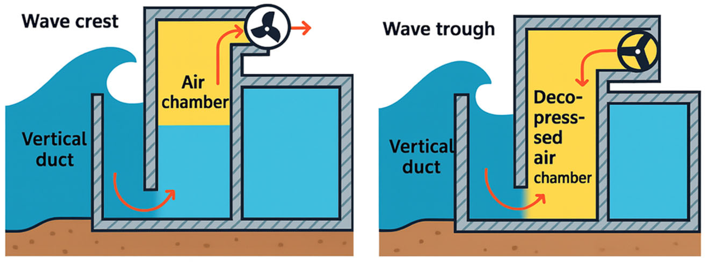
  • Oscillating Water Columns (OWCs): Utilize air compression and decompression within a chamber to drive bidirectional turbines (Figure 1). They are technologically mature but limited by moderate efficiency (40–55%).
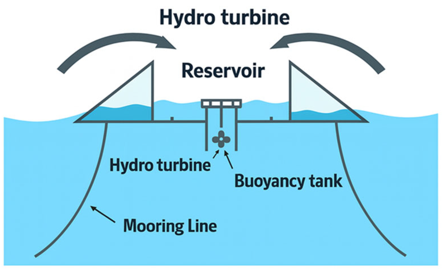
  • Overtopping Systems: Capture wave crests in elevated reservoirs and release the stored water through hydraulic turbines (Figure 2). They provide relatively stable output but require massive infrastructure and achieve modest efficiency (15–25%).
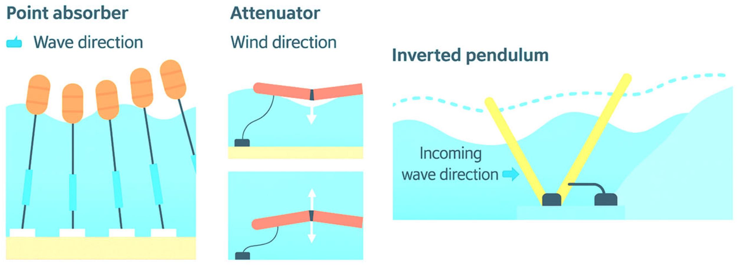
  • Oscillating Bodies: Exploit the motion of floating or submerged structures relative to a fixed reference (Figure 3). These include point absorbers, attenuators, and terminators, achieving potential efficiencies above 80% in controlled conditions. However, mechanical complexity and survivability in harsh seas are major issues [7].

2.3. Classification by Power Take-Off (PTO) System

The PTO defines how mechanical energy is transformed into electricity [8,9,10,11]:
  • Direct Mechanical Systems: Involve gears, levers, or linear generators to directly convert motion. They are simple and efficient (80–90%) but suffer from discontinuous input, requiring flywheels or other smoothing devices.
  • Hydraulic Systems: Widely used in oscillating body devices, they employ pumps and high-pressure fluids driving hydraulic motors and generators. They allow energy regulation but suffer from friction losses and complexity.
  • Pneumatic Systems: Typical of OWC devices, where airflow drives turbines. They are mechanically simple but limited by turbine efficiency (30–45%).
A summary comparison is reported in Table 1.

2.4. Real-World Applications

Several pilot projects have demonstrated the feasibility of WECs:
  • The LIMPET plant in Scotland is the first grid-connected commercial wave energy device, based on OWC technology [12].
  • The OE-Buoy in Ireland, a floating OWC system reaching up to 2.5 MW [13].
  • The Wave Dragon in Denmark, a floating overtopping device capable of 4 MW, combining wave and wind energy [14].
  • The OBREC project in Italy, integrated into a breakwater at Naples harbor [15].
  • Point absorbers such as Power Buoy and Archimedes Wave Swing [16].
  • The ISWEC (Inertial Sea Wave Energy Converter) developed by Politecnico di Torino, using gyroscopic PTO [17].
  • The Pelamis attenuator, tested in Portugal [18].
  • Terminator-type devices such as Stingray, Oyster, and Eco Wave Power [19].
These case studies illustrate the richness of design solutions but also highlight difficulties in scaling prototypes into reliable commercial plants.

3. Description of the Proposed Mechanical System

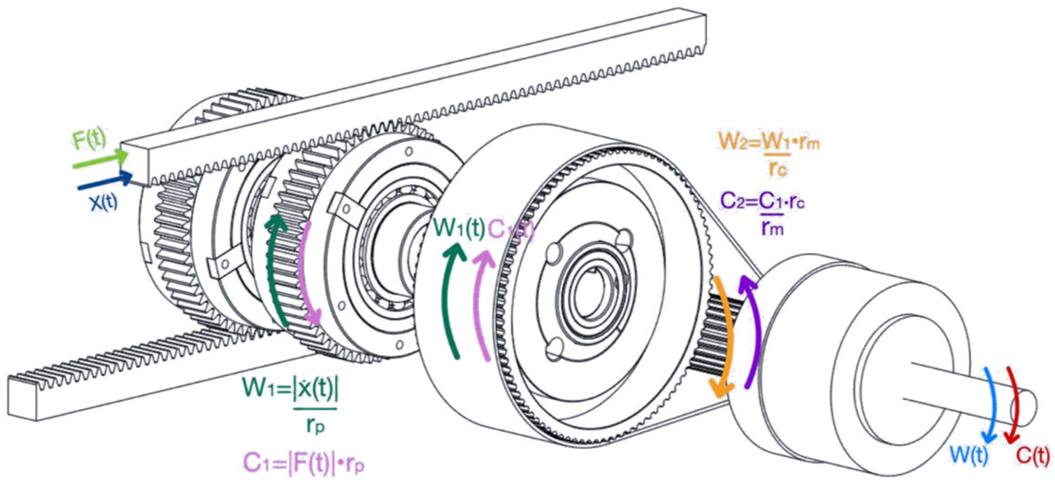
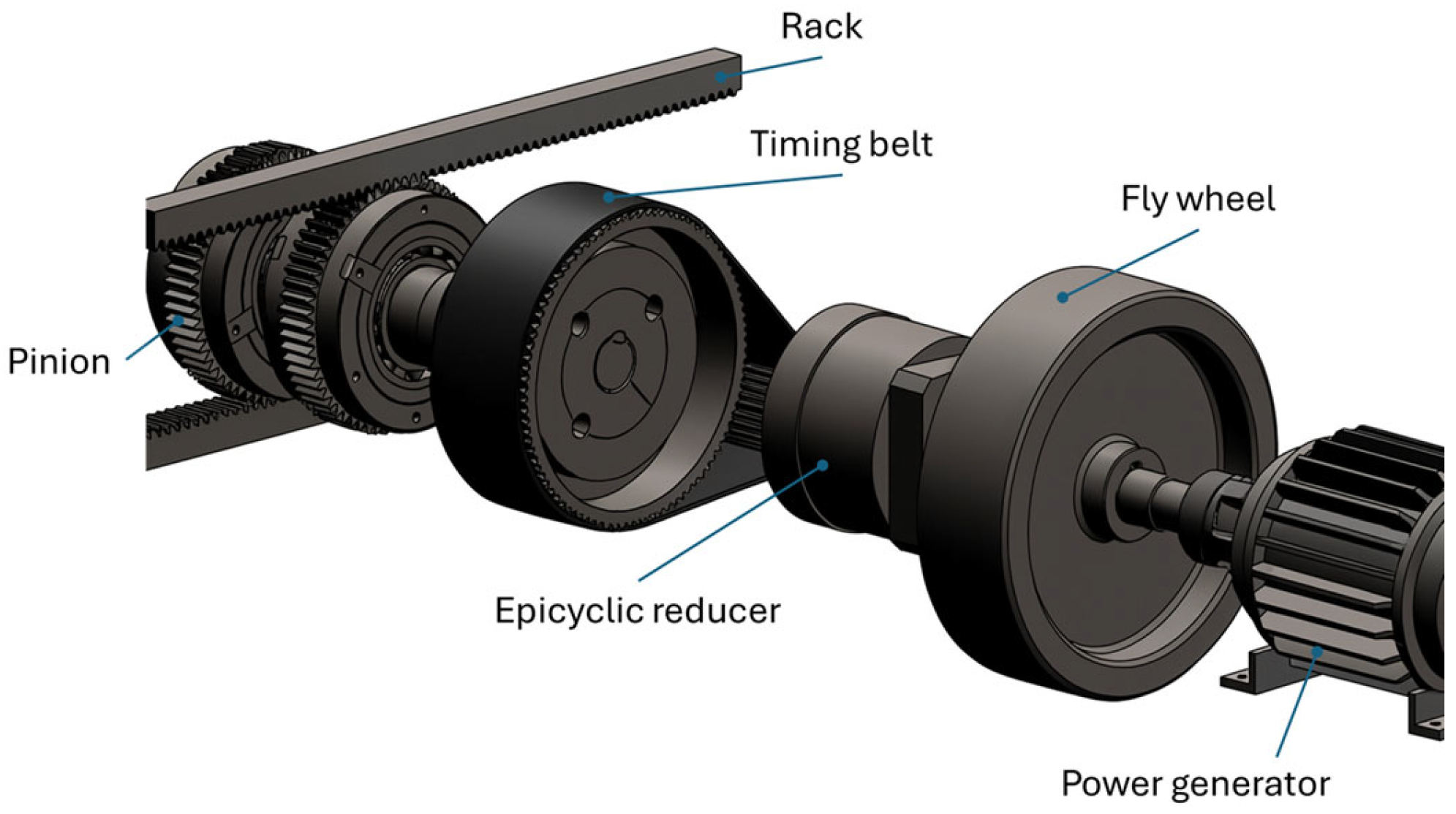
The mechanical system investigated in this work is designed to transform an oscillatory linear motion, typical of ocean waves, into a continuous unidirectional rotary motion suitable for driving an alternator (Figure 4). The device integrates linear-to-rotary conversion, freewheel clutches, transmission elements, and an energy storage flywheel [5].
The system begins with two parallel racks, mounted within a rigid housing sliding horizontally along four ball-bearing guides. The housing is subjected to an external harmonic force of the type:
F ( t )   =   F 0   ·   s i n   ( Ω · t )
where F 0 = 5000   [ N ] is the maximum applied force, and Ω = 2 π T   [ r a d s ] is the angular frequency corresponding to a wave period of t = 4 [s].
The racks mesh with two pinions, each equipped with a freewheel mechanism, and both pinions are coaxially mounted on a single shaft. The freewheels play a rectifying role: one engages when the housing moves in one direction, while the other engages when the motion reverses. This ensures that the output shaft always rotates in the same direction, effectively acting as a mechanical rectifier.
The primary shaft is then connected to a secondary shaft through a toothed belt transmission and an epicyclic gear train acting as a speed multiplier. The belt transmission ratio is 3.6, while the planetary gear provides an additional ratio of 10, giving a total multiplication factor of about 36. This arrangement elevates the output rotational speed to values suitable for an alternator.
To stabilize rotational speed and reduce oscillations induced by the reciprocating input, a flywheel is coupled to the secondary shaft. Its design is based on energy balance and degree of irregularity criteria, ensuring compatibility with alternator requirements [20,21].

4. Kinematic and Dynamic Analysis

The housing, and thus the racks, are subjected to the sinusoidal input force of Equation (1), Figure 5. Neglecting stiffness and damping effects in the first approximation, the displacement of the racks can be written as
x ( t ) = A · s i n ( Ω · t )
with amplitude A = 0.5 m in the studied case.
Velocity:
a ( t ) =   A · Ω · s i n ( Ω · t )
Acceleration:
a ( t ) =   A · Ω 2 · s i n ( Ω · t )
The racks engage with pinions of primitive radius rp = 90 mm. Thus, the angular velocity and angular acceleration of the first shaft are:
w 1 ( t ) = | v ( t ) | r p = A   r p   · Ω   · | c o s ( Ω · t ) |
α 1 ( t ) = d w 1 d t = A   r p   · Ω 2 · s i n ( Ω · t )
The corresponding torque transmitted to shaft 1 is
C 1 ( t ) = | F ( t ) | ·   r p = F 0 ·   r p · | s i n ( Ω · t ) |
With a total gear ratio i = 36, the secondary shaft rotates at:
w 2 ( t ) = w 1 ( t ) · i =   A   r p   · Ω · i · | c o s ( Ω · t ) |
α 2 ( t ) = d w 2 d t = A   r p   · Ω 2 · i · s i n ( Ω · t )
while the torque becomes:
C 2 ( t ) = C 1 ( t ) i = F 0 ·   r p i · | s i n ( Ω · t ) |
The maximum mechanical power at the secondary shaft is therefore:
P m M A X = C 2 M A X · w 2 M A X
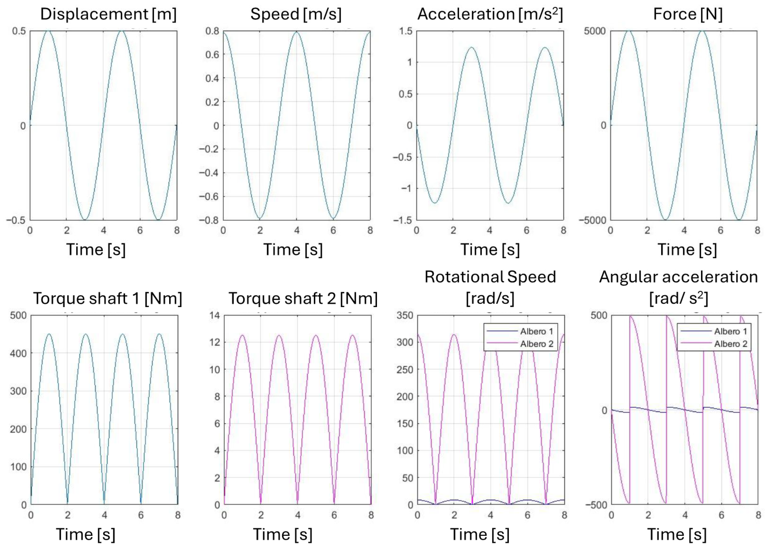
The analysis reveals strong oscillations in angular velocity and torque due to the sinusoidal input force (Figure 6). Without additional stabilization, the alternator would operate under highly irregular conditions, leading to inefficiency and possible damage. This justifies the introduction of a flywheel, discussed in the following section, to regulate kinetic energy exchange and maintain acceptable rotational uniformity.

Flywheel Design and Optimization

Alternators require a nearly constant rotational speed to operate efficiently. To quantify speed fluctuations, the degree of irregularity is defined as
i = w m a x w m i n w m e a n
For typical alternators, i must be below 1/300 [20].
The system’s inertia before including the flywheel is given by the sum of the inertias of the pulley, planetary gear, and coupling components:
J =   J m   +   J c   +   J b   +   J r
where J m , J c , J b and J r are the inertias of the motor pulley, driven pulley, conical bushing, and gear reducer, respectively.
The required total inertia to satisfy the degree of irregularity constraint is obtained from the energy balance equation for periodic systems:
i · J T O T · w m e a n 2 = 0 ϑ ( C m C r )   d ϑ
where Cm is the driving torque, C_r the resistant torque, and θ the angular displacement.
Solving yields:
J T O T   = t 1 t 2 (   C 2   ( t ) C r   ) · w 2 ( t ) ·   d t i · w 2 m e d i o 2
The required flywheel inertia is therefore:
J f l y w h e e l   =   J T O T     J = 5.7671 [ k g · m 2 ]
Considering stainless steel with density ρ = 7800 Kg/m3, and thickness h = 100 mm several flywheel configurations were evaluated:
  • Solid disk:
J f l y w h e e l = 1 2 · m s o l i d   · R s o l i d 2 = 1 2   ·   ρ s t e e l   ·   π   ·   R s o l i d 4   · h
with required radius R ≈ 0.26 [m] and mass m ≈ 168 kg.
  • Hollow cylinder:
J f l y w h e e l = 1 2   · m h o l l o w   · ( R e 2 + R i 2 ) = 1 2   · ρ s t e e l   ·   π   · h   ·   ( R e 2 R i 2 ) · ( R e 2 + R i 2 )
with inner-to-outer radius ratio k = R i R e = 0.75 . This yields slightly reduced mass for the same inertia.
Alternative designs included perforated and semi-solid structures, allowing trade-offs between mass, inertia, and manufacturability.
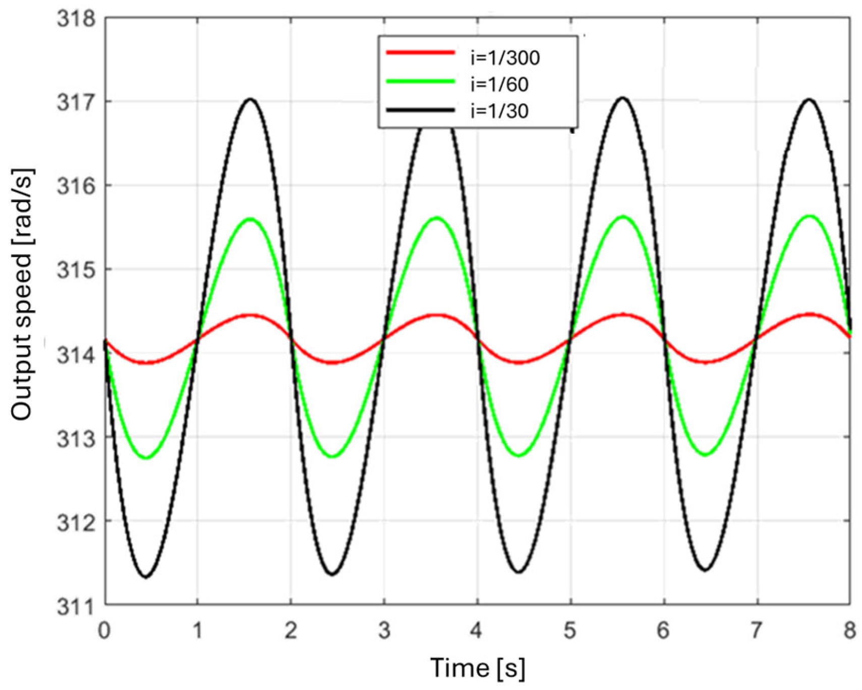
The effect of the flywheel is shown in Figure 7.

5. Efficiency Analysis

5.1. Efficiency of Mechanical System

The global efficiency of the mechanical system depends on transmission losses and flywheel stabilization [20,21]. The efficiency is defined as
η = P o u t P i n
where Pout is the mechanical power delivered to the alternator and Pin is the input wave-induced power.
For the studied configuration, the efficiency has been calculated considering the losses of all the components, as follows:
  • Recirculating Ball Guides
According to the THK catalog, the friction coefficient for an SHS guide is
μ = 0.003
The efficiency is calculated as
η = 1/(1 + μ)
Since the system consists of four carriages, the value is raised to the fourth power:
η = 0.988
  • Rack and Pinion Gears
For the rack and pinion gear set, a high efficiency is assumed:
η = 0.99
  • Freewheels
The system includes two NFR freewheels, each consisting of two 16,014 bearings (Figure 1).
From SKF data, the power loss for each bearing is obtained, and efficiency is expressed as
η = P t r a n s m i t t e d P l o s s P t r a n s m i t t e d
This value is raised to the fourth power:
η = 0.999
Radial force is calculated assuming a pressure angle of α = 20°:
F r   =   F t   ·   tan α =   1820   N
Power loss at ω1 = 83.33 rpm: P l o s s   =   0.22   W .
  • UCP-208 Bearings
A conservative assumption is made by assigning the full radial force to each bearing.
Power loss: P_loss = 1.9 W.
Efficiency:
η   =   P t r a n s m i t t e d     P l o s s P t r a n s m i t t e d =   0.999
  • Timing Belt
For the toothed belt transmission, according to the SIT company catalogue, the efficiency is estimated as
η = 0.98
  • Epicyclic Gear Reducer
From the manufacturer’s catalog, the efficiency of the VRL 155 single-stage planetary reducer is
η = 0.95
  • UCP-207 Bearings
For the two UCP-207 bearings, the radial force is estimated as
F r = ( F t · r m o t o r   p i n i o n )   ·   tan α
At ω2 = 3000 rpm, the power loss is
Ploss = 51 W
Efficiency:
η   =   P t r a n s m i t t e d     P l o s s P t r a n s m i t t e d =   0.972
  • Overall Efficiency
The total mechanical efficiency is obtained by multiplying the efficiencies of all transmission elements:
ηTOT = 0.884
Thus, the resulting output mechanical power is
P m = P m M A X   ·   η m = 3471   W

5.2. Efficiency of Hydraulic System

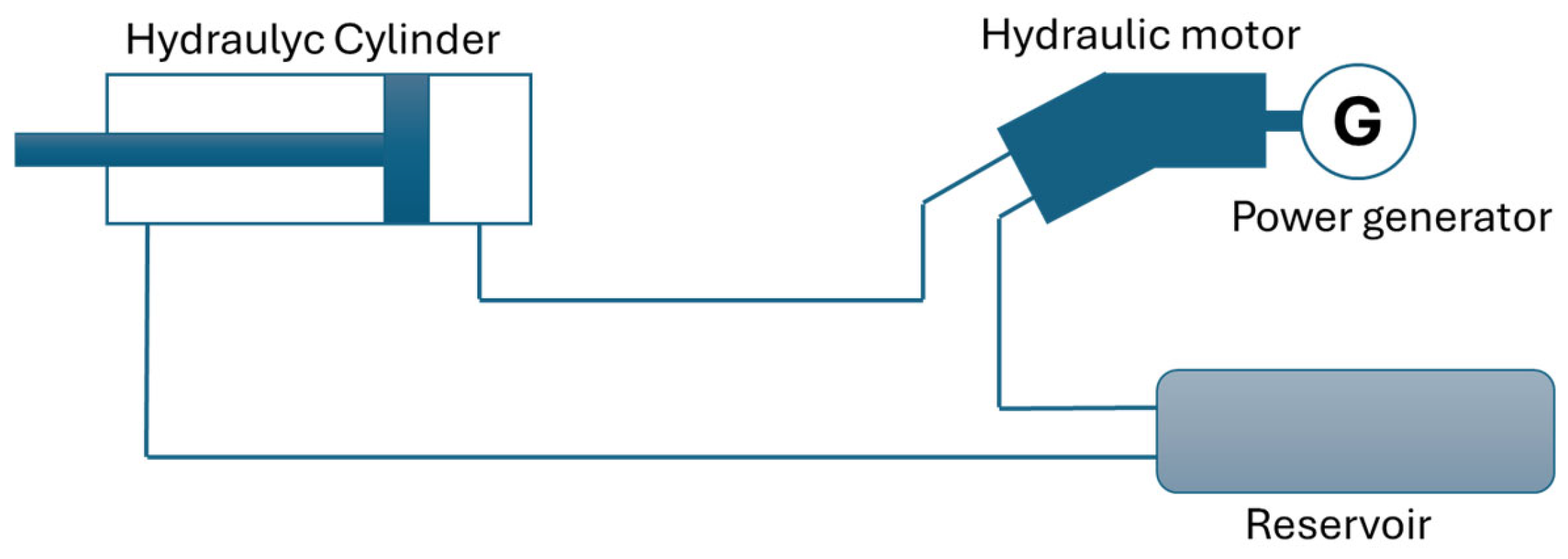
To evaluate potential advantages, the proposed mechanical solution was compared with a conventional hydraulic system of equivalent scale (Figure 8) [19]. Hydraulic PTOs, while widely used in oscillating body WECs, introduce several inefficiencies:
  • Energy losses due to viscous friction in pumps, pipes, and hydraulic motors.
  • Requirement of high-pressure circuits, accumulators, and control valves.
  • Maintenance challenges due to fluid leakage and component wear in marine environments.
The system consists of an array of articulated floaters anchored to a fixed structure. These floaters rise and fall following the wave motion, thereby driving a closed hydraulic circuit comprising the following elements:
  • A hydraulic piston mechanically connected to the floater;
  • A hydraulic accumulator that stores energy in the form of pressure;
  • A hydraulic motor driven by the pressurized fluid;
  • An electric generator coupled to the motor, which converts mechanical energy into electrical energy.
The vertical displacement of the floaters actuates the hydraulic piston, generating pressure in the fluid. This energy is temporarily stored in the accumulator and subsequently released in a controlled manner to drive the hydraulic motor, which in turn powers the generator.
To enable a direct comparison with our previously analyzed mechanical device, the following parameters are assumed to be equal for both systems:
  • Output power from the hydraulic motor equal to that of our device: Pout ≈ 3.5 kW;
  • Piston stroke and oscillation period equal to those of the rack mechanism of our device.
The efficiency analysis is carried out by back-calculating losses, starting from the hydraulic motor and proceeding upstream in the system. According to manufacturer data (e.g., Bosch Rexroth A2FM and similar models), piston-type hydraulic motors—commonly employed in marine and offshore applications due to their robustness and efficiency—exhibit typical characteristics:
  • Output power: 2–10 kW per unit;
  • Operating pressure: 100–250 bar;
  • Overall efficiency: 0.85–0.90.
For this study, an operating pressure is assumed as pin,motor = 210 bar with a motor efficiency of ηmotor = 0.86, accounting for both mechanical and volumetric performance. The corresponding volumetric flow rate is then:
Q   =   P o u t p i n , m o t o r   ·   η m o t o r     11.5   L / m i n
Assuming pressure losses in the circuit of Δ p c i r c u i t   =   5   b a r , the associated power dissipation is
Δ P c i r c u i t = Q   ·   Δ p c i r c u i t     100   W
The pressure at the accumulator outlet is therefore:
p o u t , a c c u m u l a t o r   =   p i n , m o t o r   +   Δ p c i r c u i t   =   215   b a r
Considering additional accumulator losses, Δ p a c c u m u l a t o r   =   10   b a r , the accumulator inlet pressure becomes:
p i n , a c c u m u l a t o r   =   p o u t , a c c u m u l a t o r   +   Δ p a c c u m u l a t o r   =   225   b a r
The accumulator efficiency is thus:
η a c c u m u l a t o r   =   p o u t , a c c u m u l a t o r p i n , a c c u m u l a t o r     0.96
Proceeding to the piston stage, the outlet pressure is
p o u t , p i s t o n = p i n , a c c u m u l a t o r + Δ p c i r c u i t = 230   b a r
Assuming a piston efficiency of η p i s t o n   =   0.95 , the required inlet pressure is
p i n , p i s t o n = p o u t , p i s t o n η p i s t o n     240   b a r
The overall input power to the system is then:
P i n   =   p i n , p i s t o n   ·   Q     4.7   k W
Accordingly, the total efficiency is
η T O T = P o u t P i n = 0.746

5.3. Comparison of Efficiency Between Mechanical and Hydraulic Systems

The maximum force required by the floater on the piston is
F M A X = P i n v M A X     6000   N
It follows that, to achieve the same output power as the mechanical system, the hydraulic system requires an additional 1000 N of force, since our direct mechanical device operated with only 5000 N. Furthermore, the hydraulic circuit results in power losses exceeding 1 kW, as only 3.5 kW are delivered at the motor from 4.7 kW at the piston input. In contrast, the mechanical device exhibited losses of less than 0.5 kW.
Finally, if the maximum available force due to wave conditions were limited to 5000 N (as initially assumed), both systems would receive an input power of approximately 4 kW. However, the hydraulic device would only deliver about 3 kW of usable power to the generator, whereas the mechanical system maintained the target output of 3.5 kW.

6. Discussion

The analysis demonstrates that the proposed mechanical conversion system:
  • Effectively rectifies oscillatory motion, producing continuous unidirectional rotation through a dual-rack and freewheel arrangement.
  • Amplifies angular velocity via belt and planetary transmission, reaching rotational speeds compatible with alternator operation (up to ~3000 rpm).
  • Stabilizes operation with a flywheel, ensuring a degree of irregularity within acceptable limits for electrical generation.
  • Delivers competitive efficiency, outperforming conventional hydraulic systems in theoretical terms, though subject to mechanical durability constraints.
The analysis of the flywheel confirms that angular acceleration and velocity oscillations are substantially reduced after coupling with the flywheel, leading to smoother power output.
Overall, the mechanical PTO with integrated flywheel emerges as a promising alternative for wave energy conversion, especially in applications where simplicity, robustness, and efficiency are prioritized over modular scalability.

7. Conclusions

This work has presented a detailed study of a novel mechanical system for wave energy conversion, emphasizing its kinematic and dynamic behavior, flywheel design, and efficiency. After reviewing the state of the art of Wave Energy Converters (WECs), the analysis focused on a rack-and-pinion mechanism equipped with freewheels to transform bidirectional linear motion into unidirectional rotation.
The results demonstrated that:
  • The device can effectively rectify oscillatory motion, ensuring continuous rotary output.
  • The inclusion of a transmission system and planetary gear raises the rotational speed to levels compatible with commercial alternators.
  • The flywheel is essential for stabilizing rotational irregularities, reducing the degree of irregularity below the threshold required for efficient electrical generation.
  • The system achieves a maximum mechanical power output of approximately 3.9 kW, with efficiency estimated at 70–80%.
  • Compared to hydraulic PTO systems, the mechanical configuration offers higher theoretical efficiency, reduced complexity, and simpler maintenance, though it requires robust design to withstand marine conditions.
From a broader perspective, this study highlights that while wave energy conversion technologies are still developing, mechanical PTO systems with integrated flywheels provide a promising path toward cost-effective and reliable exploitation of ocean energy. Future research should focus on experimental validation, material optimization for marine durability, and integration of control systems to enhance adaptability under variable wave conditions.

Author Contributions

Conceptualization, A.M.; methodology, A.M.; validation, L.M. (Luigi Mazza), L.M. (Luca Margaria) and G.C.; formal analysis, A.M. and L.M. (Luca Margaria); investigation, A.M., L.M. (Luigi Mazza), L.M. (Luca Margaria) and G.C.; resources, A.M.; writing—original draft preparation, all authors.; writing—review and editing, A.M., L.M. (Luigi Mazza), L.M. (Luca Margaria) and G.C.; project administration, A.M.; funding acquisition, A.M. All authors have read and agreed to the published version of the manuscript.

Funding

This publication is part of the project NODES, which has received funding from the MUR—M4C2 1.5 of PNRR funded by the European Union-Next Generation EU (grant agreement no. ECS00000036).

Institutional Review Board Statement

Not applicable.

Informed Consent Statement

Not applicable.

Data Availability Statement

The original contributions presented in this study are included in the article. Further inquiries can be directed to the corresponding author.

Acknowledgments

The authors acknowledge Makita Italia s.p.a. for the technical support.

Conflicts of Interest

The authors declare no conflict of interest.

References

  1. Benassai, G.; Dattero, M.; Maffucci, A. Wave Energy Conversion Systems: Optimal Localization Procedure. WIT Trans. Ecol. Environ. 2009, 126, 129–138. [Google Scholar] [CrossRef]
  2. Falcão, A.F.D.O. Wave Energy Utilization: A Review of the Technologies. Renew. Sustain. Energy Rev. 2010, 14, 899–918. [Google Scholar] [CrossRef]
  3. Zhang, Y.; Zhao, Y.; Sun, W.; Li, J. Ocean Wave Energy Converters: Technical Principle, Device Realization, and Performance Evaluation. Renew. Sustain. Energy Rev. 2021, 141, 110764. [Google Scholar] [CrossRef]
  4. Bruno, M.; Maccanti, M.; Pulselli, R.M.; Sabbetta, A.; Neri, E.; Patrizi, N.; Bastianoni, S. Benchmarking marine renewable energy technologies through LCA: Wave energy converters in the Mediterranean. Front. Energy Res. 2022, 10, 980557. [Google Scholar] [CrossRef]
  5. Mura, A. Sistema per una Produzione di Energia Elettrica o Meccanica dal Moto Ondoso. Italian Patent ITBS20090157A1, 14 September 2012. [Google Scholar]
  6. Novo, R. A Preliminay Study about Methods for Harvesting Energy from Marine Resources. Bachelor’s Thesis, Politecnico di Torino, Turin, Italy, 2015. [Google Scholar] [CrossRef]
  7. Lian, J.; Wang, X.; Wang, X.; Wu, D. Research on Wave Energy Converters. Energies 2024, 17, 1577. [Google Scholar] [CrossRef]
  8. Gobato, R.; Gobato, A.; Fedrigo, D.F.G. Study Pelamis System to Capture Energy of Ocean Wave. arXiv 2015. [Google Scholar] [CrossRef]
  9. Penalba, M.; Ringwood, J.V. A Review of Wave-to-Wire Models for Wave Energy Converters. Energies 2016, 9, 506. [Google Scholar] [CrossRef]
  10. Carraro, M. Wave Energy Extraction Using Vertical Motion Buoys: Modeling and Control (Estrazione di Energia Dalle Onde Tramite boe a Moto Verticale: Modellizzazione e Controllo). Master Thesis, Università degli Studi di Padova, Padova, Italy, 2009–2010. (In Italian) [Google Scholar]
  11. Eriksson, M.; Isberg, J.; Leijon, M. Hydrodynamic Modelling of a Direct Drive Wave Energy Converter. Int. J. Eng. Sci. 2005, 43, 1377–1387. [Google Scholar] [CrossRef]
  12. Heath, T.V. Chapter 334—The Development and Installation of the Limpet Wave Energy Converter. In World Renewable Energy Congress VI; Pergamon: Bergama, Turkey, 2000; pp. 1619–1622. [Google Scholar] [CrossRef]
  13. OE-Buoy. Available online: https://oceanenergy.ie/oe-buoy/ (accessed on 5 July 2025).
  14. Wave Dragon Project Documentation. Available online: https://tethys-engineering.pnnl.gov/sites/default/files/publications/Wave-Dragon-2009.pdf (accessed on 5 July 2025).
  15. Contestabile, P.; Crispino, G.; Di Lauro, E.; Ferrante, V.; Gisonni, C.; Vicinanza, D. Overtopping breakwater for wave Energy Conversion: Review of state of art, recent advancements and what lies ahead. Renew. Energy 2020, 147, 705–718. [Google Scholar] [CrossRef]
  16. Archimedes Waveswing. Available online: https://awsocean.com/archimedes-waveswing/ (accessed on 5 July 2025).
  17. ISWEC Project. Available online: https://morenergylab.polito.it/iswec/ (accessed on 5 July 2025).
  18. Carcas, M. The_Pelamis_Wave_Energu_Converter. Available online: https://energiatalgud.ee/sites/default/files/images_sala/3/3a/Carcas%2C_M._The_Pelamis_Wave_Energu_Converter.pdf (accessed on 5 July 2025).
  19. Eco Wave Power. Company Reports. Available online: https://www.ecowavepower.com/ (accessed on 5 July 2025).
  20. Ferraresi, G.; Raparelli, T. Meccanica Applicata, 3rd ed.; CLUT Editrice: Torino, Italy, 2007. [Google Scholar]
  21. Fasana, A.; Marchesiello, S. Meccanica delle Vibrazioni; CLUT Editrice: Torino, Italy, 2006. [Google Scholar]
Figure 1. Oscillating Water Columns systems.
Engproc 131 00043 g001
Figure 2. Overtopping systems.
Engproc 131 00043 g002
Figure 3. Oscillating body systems.
Engproc 131 00043 g003
Figure 4. Mechanical system to transform oscillating linear motion into rotating unidirectional motion.
Engproc 131 00043 g004
Figure 5. Free body diagram of the system.
Engproc 131 00043 g005
Figure 6. Kinematic and dynamic parameters vs. time.
Engproc 131 00043 g006
Figure 7. Effect of flywheel on output speed.
Engproc 131 00043 g007
Figure 8. Schematic of hydraulic circuit.
Engproc 131 00043 g008
Table 1. Comparison of systems.
PTO TypeEfficiencyComplexityMaintenanceRobustnessCost
Mechanical80–90%Low–MediumMediumHighLow–Medium
Hydraulic70–85%HighMedium–HighMediumHigh
Pneumatic30–45%MediumMediumMediumMedium
Disclaimer/Publisher’s Note: The statements, opinions and data contained in all publications are solely those of the individual author(s) and contributor(s) and not of MDPI and/or the editor(s). MDPI and/or the editor(s) disclaim responsibility for any injury to people or property resulting from any ideas, methods, instructions or products referred to in the content.