


Abstract
A new three-degree-of-freedom (3-DOF) variable-structure floating linkage mechanism is presented in this article. The proposed mechanism consists of six links, five revolute joints, and one rolling or sliding joint. In the mechanism, the fixed link of a traditional five-bar linkage and its adjacent links serve as the driving links. The mechanism is a fully rotatable five-bar linkage relative to a fixed link. Depending on which links are driven, the mechanism’s structure transforms among four-bar linkage, five-bar linkage, floating four-bar linkage, and floating five-bar linkage. A key advantage of this mechanism is its adjustable structure and workspace, and its ability to solve all planar path generation and motion generation problems within a specified workspace. Structural and positional analysis results of the mechanism developed are presented in this article, along with examples and experimental validations demonstrating its feasibility for planar path and motion generation tasks.
1. Introduction
A floating linkage mechanism refers to a linkage system that rotates freely relative to its frame. Soong [1] proposed a floating 1-DOF geared linkage mechanism that combined a five-bar linkage with a planetary gear train to generate various coupler curves.
Over recent decades, numerous studies on geared linkage mechanisms have reported findings in workspace and mobility criteria [2,3], as well as in kinematic analysis [4,5]. Extensive research has also been conducted to synthesize five-bar linkages and geared five-bar linkages for path generation, motion generation, and function generation. Several analytical synthesis methods, including variable-topology approaches and complex-number techniques, have been proposed [6]. Mundo et al. [7] applied a genetic algorithm to optimize the dimensions of five-bar linkages driven by pairs of noncircular gears for exact path generation. Lin [8] proposed an optimal path synthesis method using a combined discrete Fourier descriptor for geared five-bar linkages. Yu et al. [9] developed a two-step rigid-body guidance synthesis method for designing noncircular gear–five-bar exoskeleton knee-joint rehabilitation devices.
This research aims to develop a new 3-DOF variable-structure floating linkage mechanism. The structural and positional analyses are discussed in detail, and examples with experimental validations are presented in this article to demonstrate the feasibility for planar path and motion generation tasks.
2. Structure Analysis
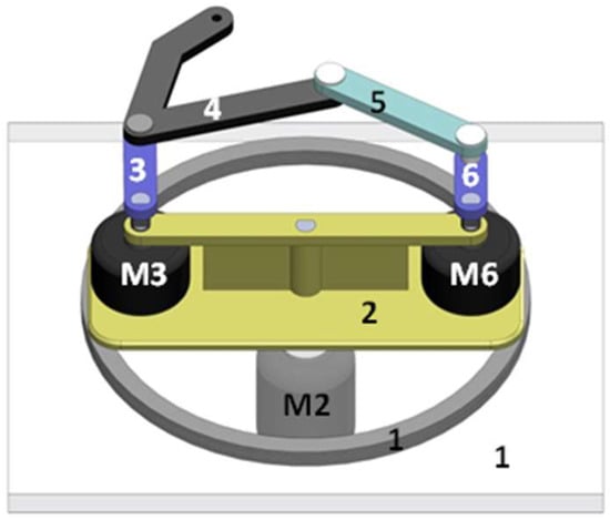
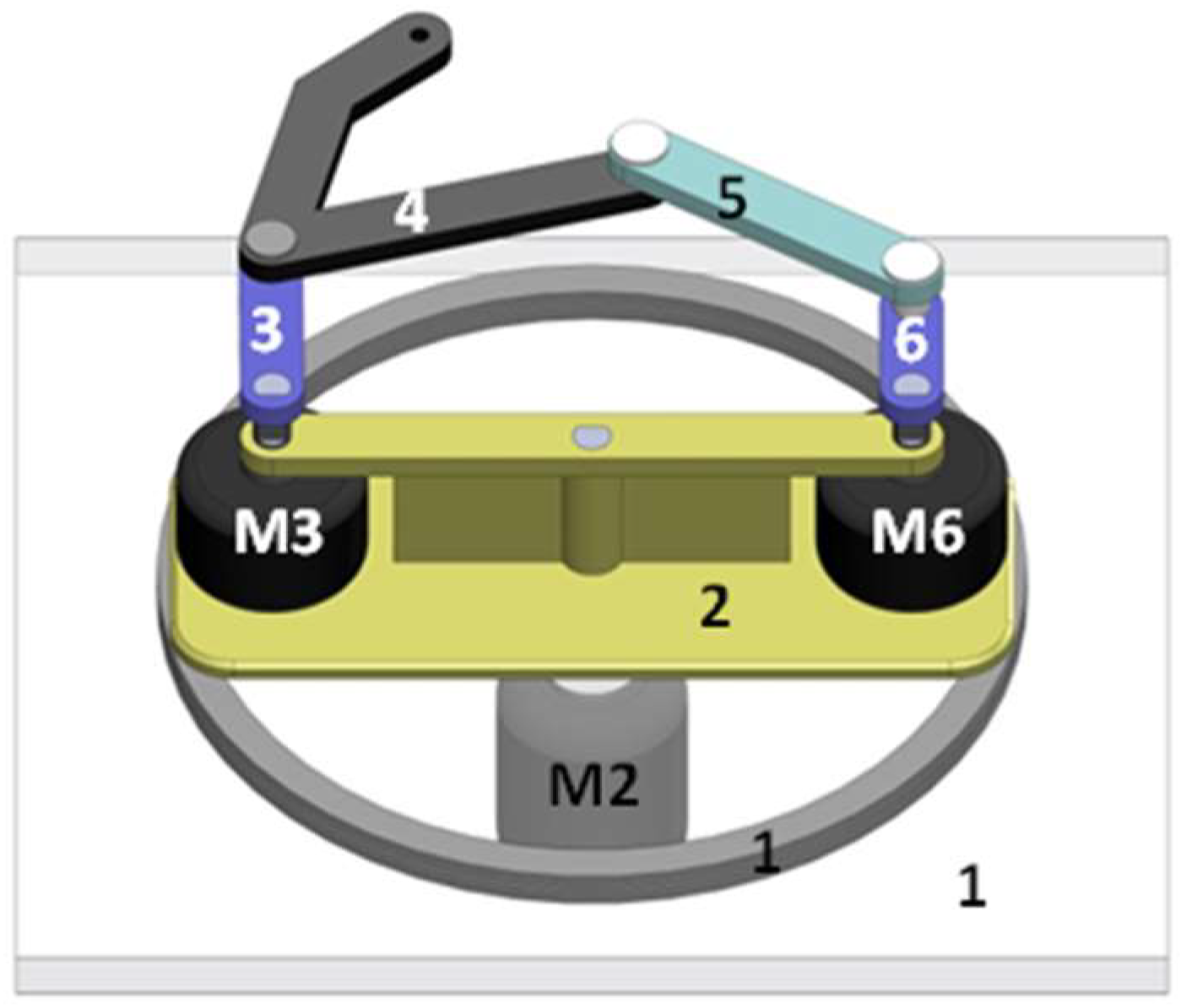
A new 3-DOF linkage mechanism with three rotational input links is shown in Figure 1. The developed mechanism is a six-bar linkage with five revolute joints and one rolling or sliding joint. The five-bar linkage formed by Links 2 through 6 rotates about the center of Link 1 (the fixed link) and is driven by a motor. Links 3 through 6 move relative to Link 2, resembling the motion of a five-bar linkage with two driving links (Links 3 and 6). Link 2 connects to Link 1 via a rolling or sliding joint. Thus, the mechanism functions as a floating five-bar linkage with 3-DOF. The mechanism’s structure can be transformed among four-bar, floating four-bar, five-bar, and floating five-bar configurations depending on whether Links 2, 3, or 6 are driven or held stationary.
Figure 1.
The 3-DOF floating five-bar linkage.
3. Position Analysis
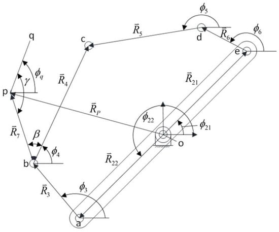
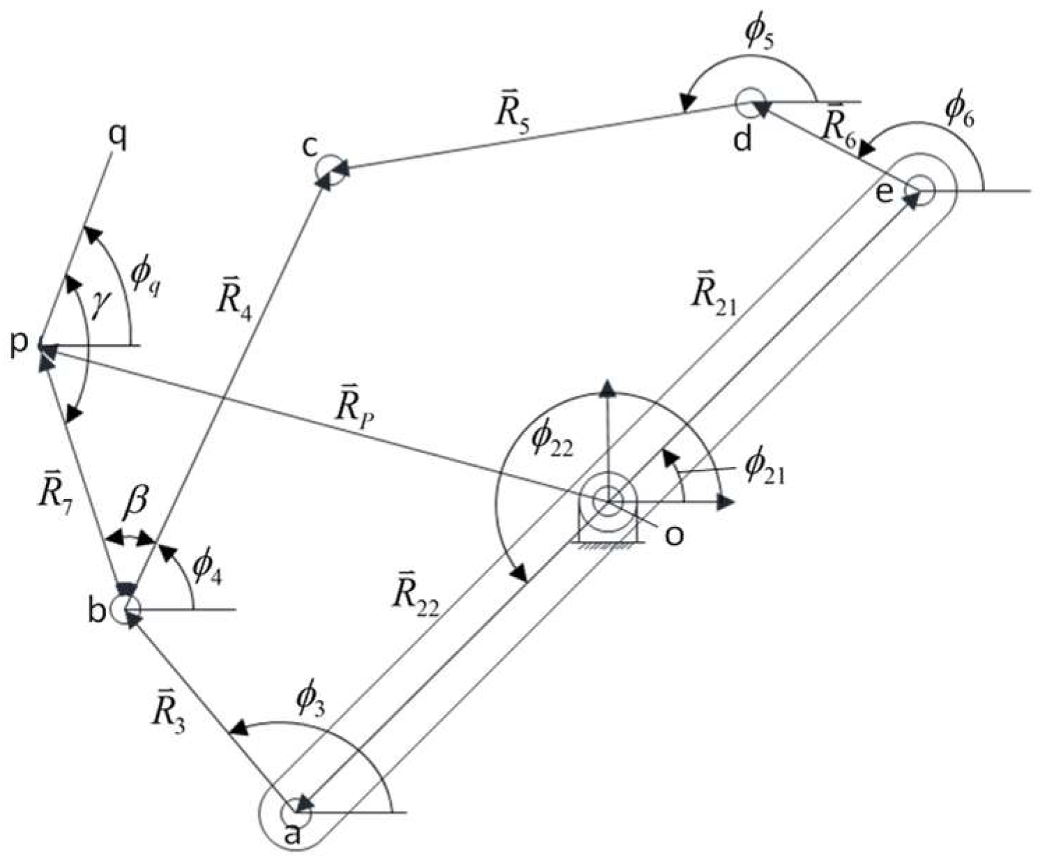
The coordinate system of the proposed mechanism is shown in Figure 2. Vector loop closure equations are employed for the kinematic analysis.
Figure 2.
The coordinate system of the 3-DOF floating five-bar linkage.
The vector loop is considered to start from position vector and end at position vector in the clockwise direction. Then, Equation (1) is derived.
Projecting the vectors onto the x- and y-axes yields the following:
where and are the respective magnitudes and directions of the vectors , i = 3–6. and are the respective magnitudes and directions of the vectors , j = 1–2.
From Equations (2) and (3), the angular positions of Link 5 and of Link 4 are obtained by simultaneous solution.
where , , , and , .
The coordinates of the coupler point p on Link 4 (Figure 2) can be written as follows:
where and are the magnitude and direction of the vector , respectively, as shown in Figure 2.
When the Cartesian coordinates of each precision point on the desired path of coupler point p are specified, the following vector loop equation is applied:
The scalar equations are formulated as follows:
where (rpx, rpy) are the known coordinates of the coupler point p. Solving Equations (9) and (10) yields the instantaneous angular positions φ3 and .
where , , , , , and (, ) are the known coordinates of the coordinate origin. Once and are known, the corresponding angular positions of Link 6 and Link 5, and , are determined by substitution into the earlier loop closure equations.
where , , and , , and .
For motion generation problems, both the path of point p and the angular orientation of the coupler link at each precision point are specified. In Figure 2, point p moves through a set of specified precision points, and segment is constrained to pass through specific orientations.
Because , , and are known, the required angular position of Link 4 corresponding to the precise point is expressed as follows:
Once is determined, the solution of Equations (9) and (10) yields the instantaneous angular positions of Link 3 and Link 2, respectively.
where , , , , , , and .
Once and are obtained, the instantaneous angular positions of Link 5 and Link 6 can be determined by solving Equations (13) and (14).
4. Kinematic Examples
To ensure that Link 3 and Link 6 act as cranks in the proposed mechanism, the link lengths must satisfy , where and are the two shortest links, and is the longest link. The other two links must be chosen to satisfy certain geometric constraints [4]. An example set of link lengths is given in Table 1.
Table 1.
Dimensions of the example kinematic mechanism.
4.1. Example of Path Generation
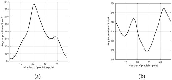
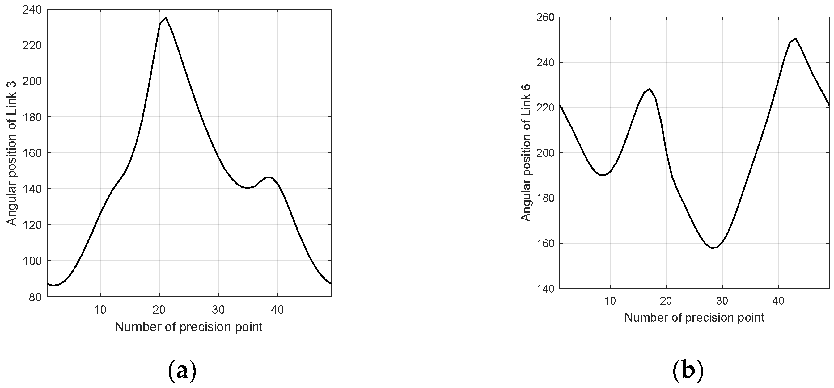
Using inverse kinematics, the angular positions of Links 3 and 6 are calculated for 49 precision points along a specified ∞-shaped path that the coupler point p must pass through. To ensure that each precision point lies within the coupler’s workspace, Link 2 is fixed at 55° relative to the horizontal axis in this example. Figure 3 shows the required angular positions of Links 3 and 6 for each precision point.
Figure 3.
The angular positions of Links 3 and 6 corresponding to each precision point. (a) Angular position of Link 3; (b) angular position of Link 6.
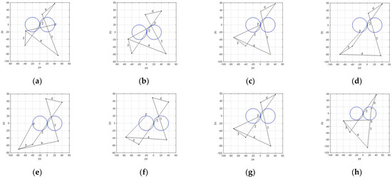
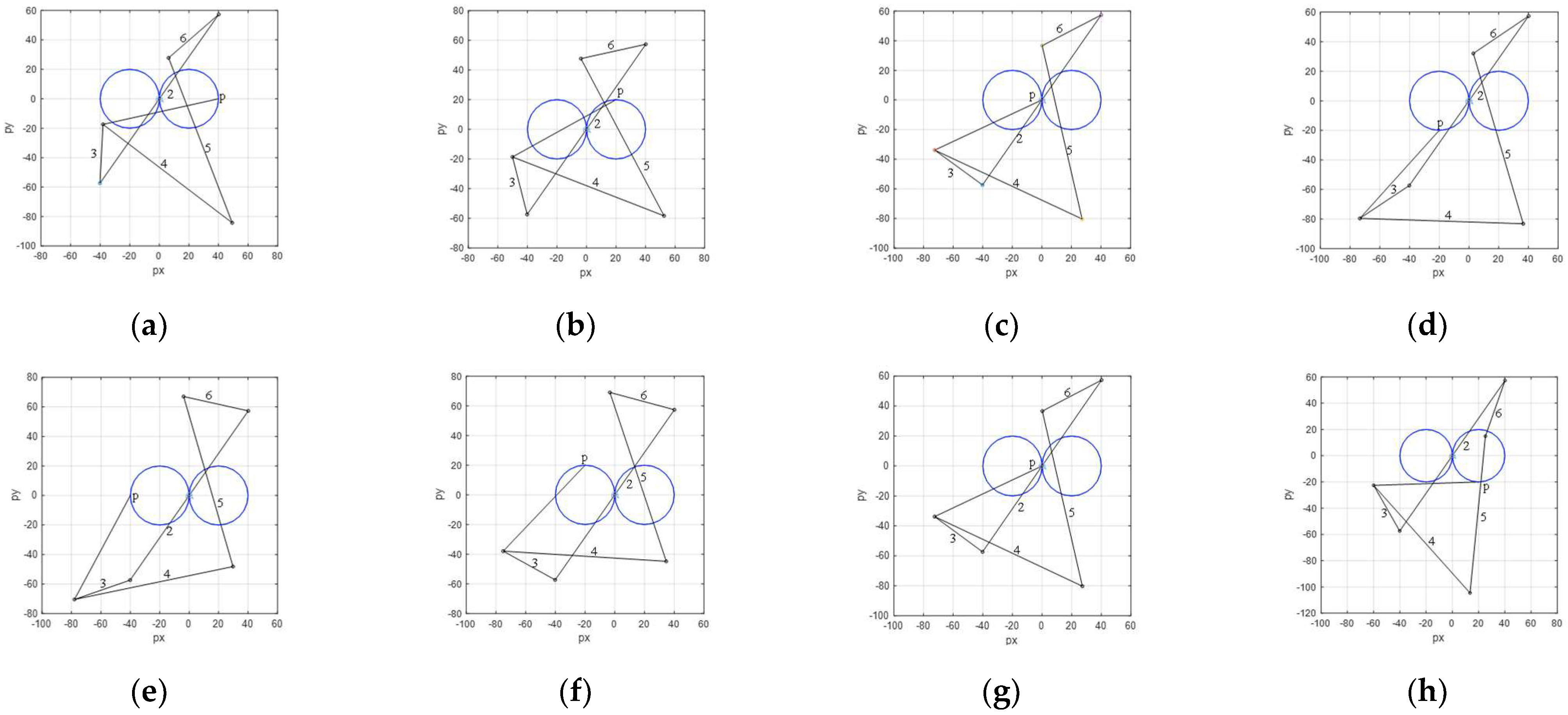
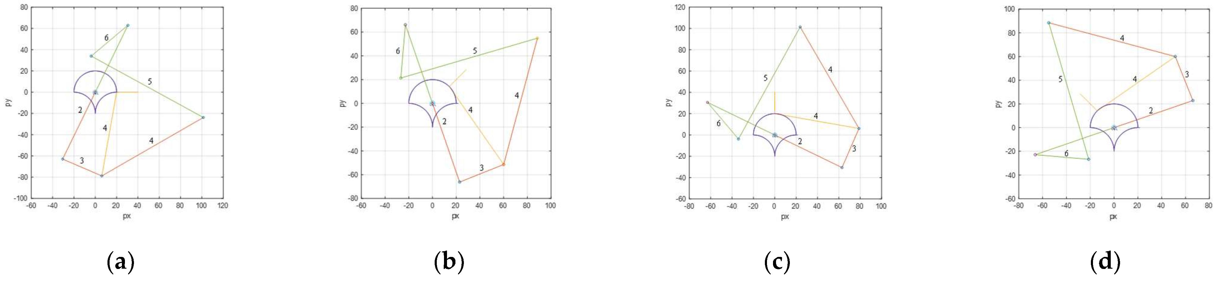
In Figure 4, the coupler point p of the floating five-bar linkage traces the specified closed path accurately. The figure also shows mechanism configurations at different precision points along the path.
Figure 4.
Mechanism configurations at selected precision points along the ∞-shaped path. (a) 1st precise point, (b) 7th precise point, (c) 13th precise point, (d) 19th precise point, (e) 25th precise point, (f) 31st precise point, (g) 37th precise point, and (h) 43rd precise point.
4.2. Example of Motion Generation
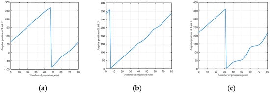
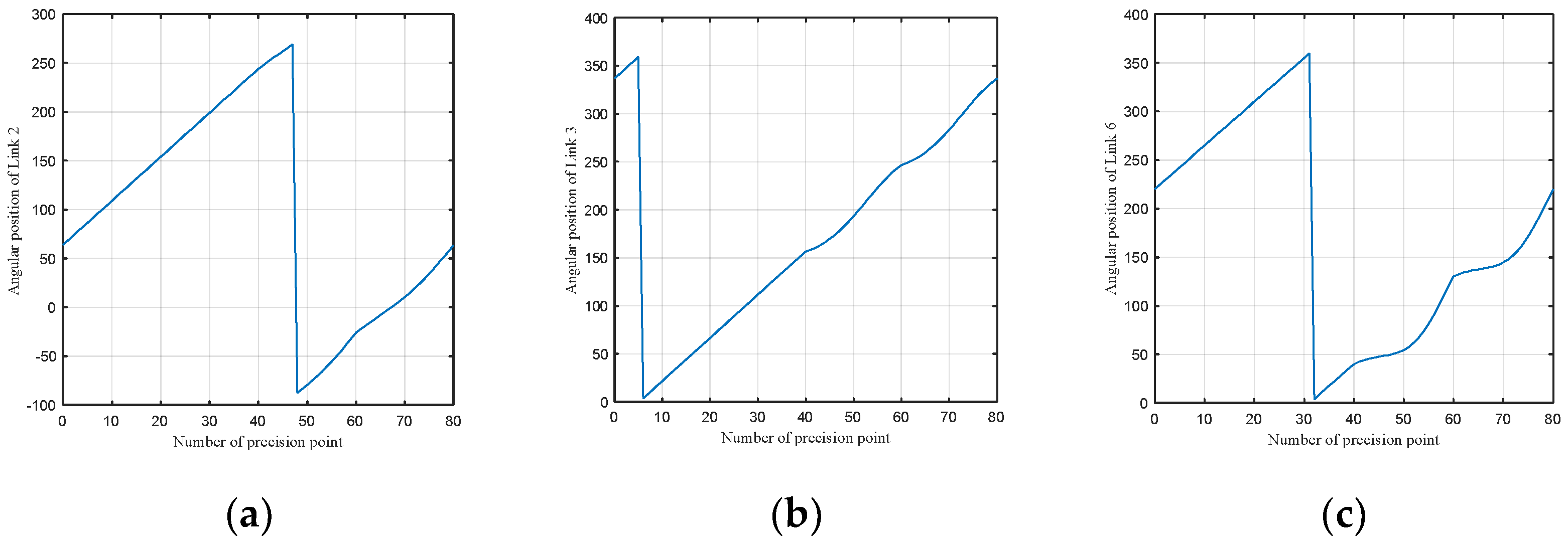
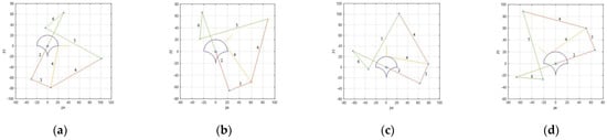
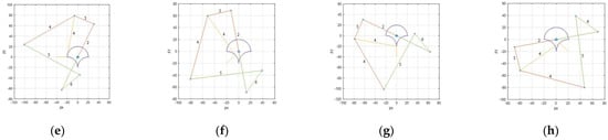
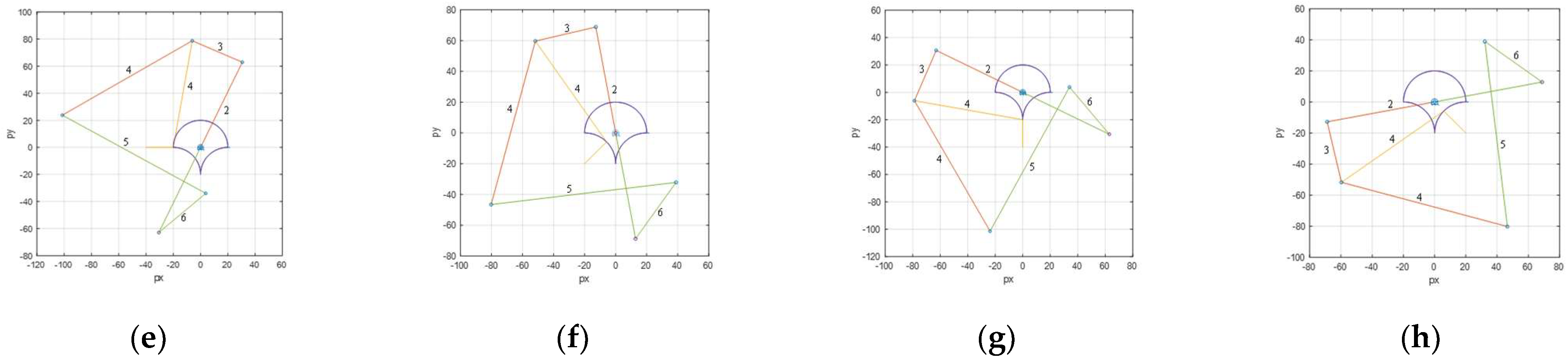
Point p in Figure 2 passes through 70 precision points on the specified path, while line segment is oriented along the local normal at each point. This ensures that both the position and orientation requirements are satisfied at each precision point. The angular positions of Links 2, 3, and 6 are plotted in Figure 5, and Figure 6 shows the mechanism configurations for eight representative precision points and orientations.
Figure 5.
Angular positions of Links 2, 3, and 6 corresponding to each precision point. (a) Angular position of Link 2; (b) angular position of Link 3; (c) angular position of Link 6.
Figure 6.
Mechanism configurations at selected precision points and orientations. (a) 1st precise point, (b) 11th precise point, (c) 21st precise point, (d) 31st precise point, (e) 41st precise point, (f) 51st precise point, (g) 61st precise point, and (h) 71st precise point.
5. Validation
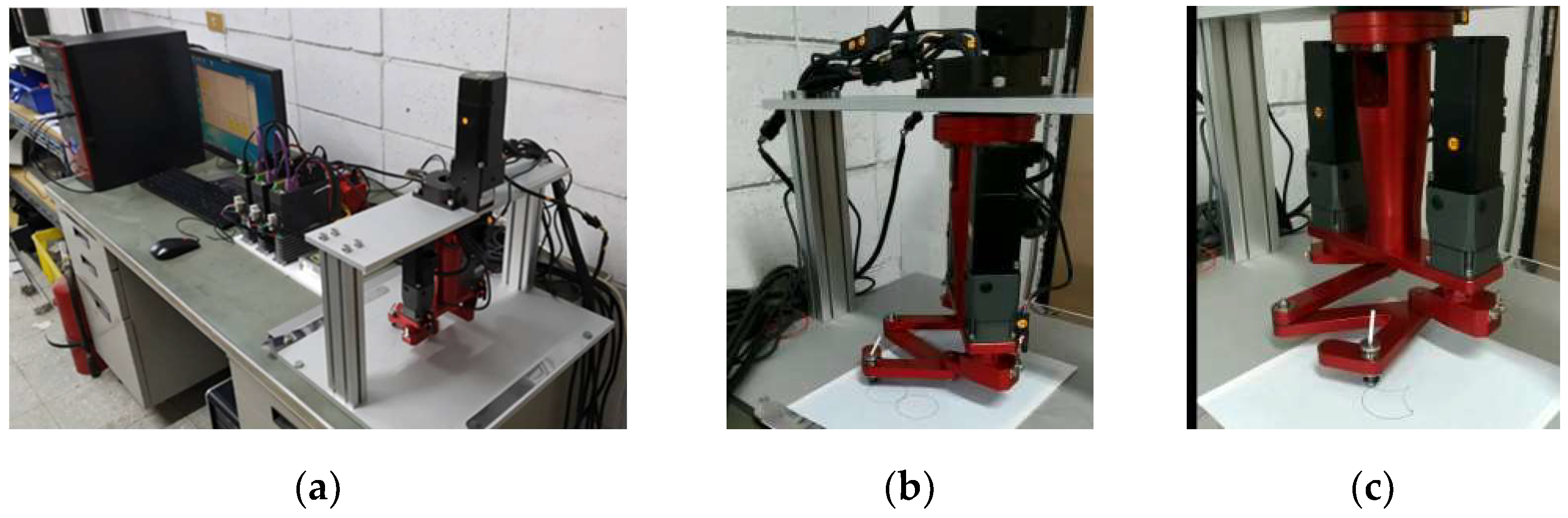
A prototype of the 3-DOF floating linkage was built and tested using three servo motors and drivers, controlled by a four-axis motion-control card and a personal computer. Figure 7 illustrates the experimental mechanism, peripheral equipment, and the overall experimental setup. Two experiments were conducted: one generating an ∞-shaped path and another generating a shell-shaped path with simultaneous orientation control. Figure 7 presents the experimental results, confirming that the proposed mechanism achieves the intended path and motion generation objectives.
Figure 7.
The experimental mechanism, setup, and results. (a) Overall experimental architecture, (b) ∞-shaped path generation, and (c) shell-shaped path and motion generation.
6. Conclusions
This article presents a new 3-DOF floating linkage mechanism composed of six links, five revolute joints, and one rolling or sliding joint. The developed mechanism effectively functions as a five-bar linkage mounted on a base link via a rolling or sliding joint, allowing it to act as a fully rotatable five-bar linkage. Depending on which links are driven, the mechanism can transform among four-bar, five-bar, floating four-bar, and floating five-bar configurations. Because its structure and workspace are adjustable, this mechanism theoretically solves all planar path and motion generation problems within a specified working region more flexibly than traditional linkage mechanisms. This article also presents structural and positional analyses of the proposed mechanism, as well as illustrative examples and experimental validations, confirming its feasibility for planar path and motion generation tasks.
Funding
This research was supported by the National Science Council of ROC (Taiwan) under grant MOST 109-222-E-224-001.
Institutional Review Board Statement
Not applicable.
Informed Consent Statement
Not applicable.
Data Availability Statement
Data is contained within the article.
Acknowledgments
This research was supported by the National Science Council of Taiwan under grant MOST 109-222-E-224-001.
Conflicts of Interest
The authors declare no conflict of interest.
References
- Soong, R.C. On the Study of the Floating Linkage Mechanisms. In AIP Conference Proceedings; AIP Publishing: New York, NY, USA, 2023; Volume 2685, p. 020009. [Google Scholar] [CrossRef] [Scilit]
- Seth, B.; Vaddi, S.S. Programmable function generators–I: Base five-bar mechanism. Mech. Mach. Theory 2003, 38, 321–330. [Google Scholar] [CrossRef] [Scilit]
- Li, R.; Dai, J.S. Workspace atlas and stroke analysis of seven-bar mechanisms with translation-output. Mech. Mach. Theory 2012, 47, 117–134. [Google Scholar] [CrossRef] [Scilit]
- Neu, X.; Zhao, J. Kinematic analysis of a planar five-bar mechanism with actuation redundancy. Mech. Mach. Theory 2016, 99, 52–63. [Google Scholar]
- Lin, T.J.; Cao, W.Q. Kinematic analysis of the geared linkage mechanisms. Mech. Mach. Theory 2005, 40, 1394–1413. [Google Scholar] [CrossRef] [Scilit]
- Balli, S.S.; Chand, S. Synthesis of a Five-Bar Mechanism of Variable Topology Type with Transmission Angle Control. ASME J. Mech. Des. 2004, 126, 128–134. [Google Scholar] [CrossRef] [Scilit]
- Mundo, D.; Gatti, G.; Dooner, D.B. Optimized five-bar linkages with non-circular gears for exact path generation. Mech. Mach. Theory 2009, 44, 751–760. [Google Scholar] [CrossRef] [Scilit]
- Lin, W.Y. Optimum path synthesis of a geared five-bar mechanism. Adv. Mech. Eng. 2013, 5, 757935. [Google Scholar] [CrossRef] [Scilit]
- Yu, C.; Yao, K.; Zong, Y.; Ye, J.; Chen, J. Rigid-Body Guidance Synthesis of Noncircular Gear-Five-Bar Mechanisms and Its Application in a Knee Joint Rehabilitation Device. Machines 2022, 10, 1110. [Google Scholar] [CrossRef] [Scilit]

Disclaimer/Publisher’s Note: The statements, opinions and data contained in all publications are solely those of the individual author(s) and contributor(s) and not of MDPI and/or the editor(s). MDPI and/or the editor(s) disclaim responsibility for any injury to people or property resulting from any ideas, methods, instructions or products referred to in the content. |
© 2026 by the author. Licensee MDPI, Basel, Switzerland. This article is an open access article distributed under the terms and conditions of the Creative Commons Attribution (CC BY) license.