


Abstract
The development of wearable devices continues to be a growing trend. The mobile health wearables market is extremely fast-moving, with wearable ECG designs demanding increasingly complex features from manufacturers, such as size reduction, high accuracy, low weight, power efficiency, and good signal quality. The AD823X integrated circuits for ECG miniaturization, as an analog front-end (AFE), provide an amplified and filtered analog signal for subsequent digitization. The aim of this work is the development of expansion boards for portable ECG applications based on the AD823X microchip and the Arduino platform. This study includes three different circuit designs for specific ECG applications: cardiac monitor, ECG fitness, and Holter monitor. It also presents designs using both AD823X integrated circuits. After performing tests with analog stage, the Atmega328 microcontroller was used for the analog-to-digital conversion of the ECG signals, and a miniaturized custom breakout board was developed for each ECG application, incorporating a CSR BC417143 chip for Bluetooth connectivity. The digitized signals can be transmitted by serial cable, via Bluetooth to a PC, or to an Android smartphone system for visualization. Other performed tests included measuring the noise induced during the analog-to-digital conversion stage of the Atmega328 microcontroller. This work evaluated, compared, and determined the best of the applications proposed by the manufacturer of the AD8232X for a wearable ECG monitor, addressing the current needs of the devices and emerging trends in mobile health.
Keywords:
ECG; AD8232; AD8233; custom PCB; Arduino ECG; ECG breakout board; wearable ECG; ECG applications 1. Introduction
According to the World Health Organization (WHO), cardiovascular diseases (CVDs) are the leading cause of death worldwide with 19.8 million deaths being attributed to CVD in 2022, equivalent to approximately 32% of total global deaths [1]. As a response to this issue, there has been an increase in the development of electrocardiographic signal acquisition devices, aimed at creating affordable equipment that can provide an ECG signal useful for morphology analysis [2]. Some studies, such as [3,4,5], have used the SparkFun commercial analog front end (AFE) or versions based on that board that incorporate the AD8232 chip in a heart monitor configuration [6]. This chip, besides being affordable, allows the acquisition of the ECG signal using a voltage between 2.0 and 3.5 V with a common energy consumption of 170 µA [7], making it a viable option for implementation in prototype development. However, the dimensions of the commercial AFE present a limitation when creating devices that aim to be miniaturized. Furthermore, the commercial AFE has a heart monitor configuration, where the manufacturer recommends that the patient remain still when acquiring signals, limiting the quality and flexibility of the development of wearable devices with characteristics of the mobile health (mHealth) paradigm [6,7].
As mentioned in [8], aspects such as weight, compactness, low energy consumption, data transmission media, and device miniaturization are fundamental characteristics when developing mHealth devices. For these reasons, the development of AFEs using the AD8232 chip by Analog Devices (Wilmington, MA, USA) is proposed for different applications using the configurations provided by the manufacturer [7]. In addition, different printed circuit boards (PCBs) were designed with different contexts in mind where AFEs can be employed. The first version of the PCB provides only the analog signal with a 3.3 V power supply, while the second version can transmit data analogically via a pin and via Bluetooth using the Arduino ATmega328p microcontroller by Microchip Technology (Chandler, AZ, USA) and the CSR BC417143 integrated circuit contained in the HC-06 modules by Cambridge Silicon Radio (Cambridge, UK) with a 5 V to 13.8 V power supply. The latest version of the PCB, in addition to including all the previously mentioned features, has a Mini-B USB port by TE Connectivity (Galway, Ireland) that allows the acquired data to be transmitted via cable, as well as allowing the microcontroller to be reprogrammed, along with two extra analog pins available for use, providing more flexibility for its application in projects.
Finally, the performances of the three applications mentioned above were compared using the AD8232 and AD8233 chips both by Analog Devices (Wilmington, MA, USA), the latter being smaller and provides a signal with less noise than the AD8232 chip [9].
2. Materials and Methods
2.1. Schematics of AD823X Chip Applications
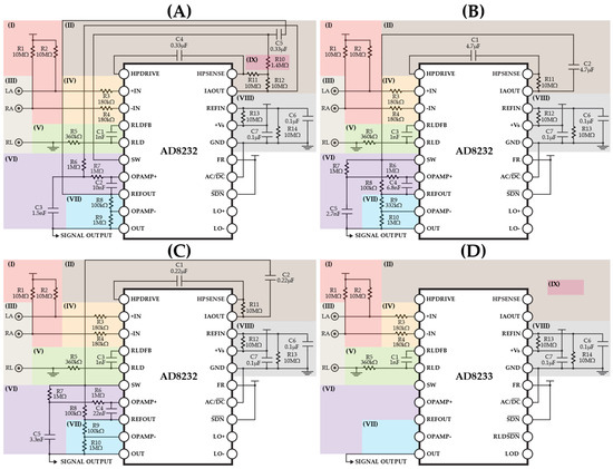
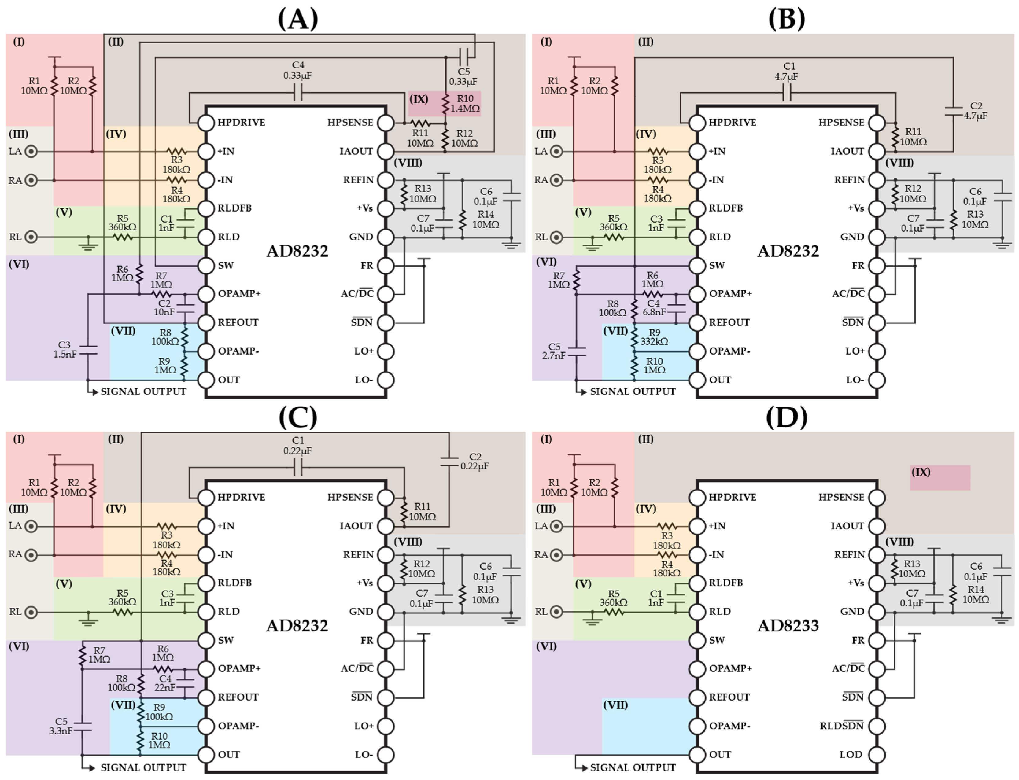
As mentioned in Section 1, three configurations of the AD8232 chip were used, as shown in their respective datasheets [7]. The application circuit (A) Cardiac monitor configuration is designed to monitor the ECG waveform when the user is stationary. This configuration uses a 0.5 Hz high-pass filter and a 40 Hz low-pass filter with a final gain of 1100. The application circuit (B) Portable cardiac monitor with elimination of motion artifacts has cutoff frequencies of 0.3 Hz and 37 Hz for the high-pass and low-pass filters, respectively, with a total signal gain of 400. This configuration is appropriate for monitoring ECG signal morphology for applications where the patient is performing moderate activity.
The circuit (C) Exercise application: Heart rate measured at the hands has a final gain of 1100 with a 7 Hz high-pass filter and a 24 Hz low-pass filter. This configuration is only appropriate for determining heart rate and not for analyzing ECG signal characteristics. Schematics (A), (B), and (C) in Figure 1 show applications A, B, and C of the AD8232 chip, respectively, while schematic (D) shows the general schematic of the AD8233 chip implementation for each of the three applications mentioned earlier. Sections (II), (IX), (VI), and (VII) of Figure 1 (D) do not show any components since each of the aforementioned applications have different components in these sections, which is not the case for section (I), (III), (IV), (V), and (VIII), which have the same configuration in all three applications.
Figure 1.
Schematics for AD823X chip applications: (A) Cardiac monitor configuration, (B) Portable cardiac monitor with elimination of motion artifacts, (C) Exercise application (heart rate measured at the hands), and (D) general schematic for AD8233 chip implementation for the previous applications. Each color section corresponds to (I) polarization resistors, (II) high-pass filter, (III) electrode section, (IV) user protection resistors, (V) protection against leakage currents < 10 uA, (VI) low-pass filter, (VII) circuit gain, (VIII) reference resistor and noise filter, and (IX) filter response compensation resistor.
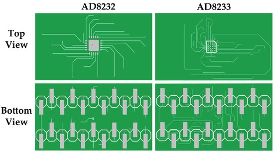
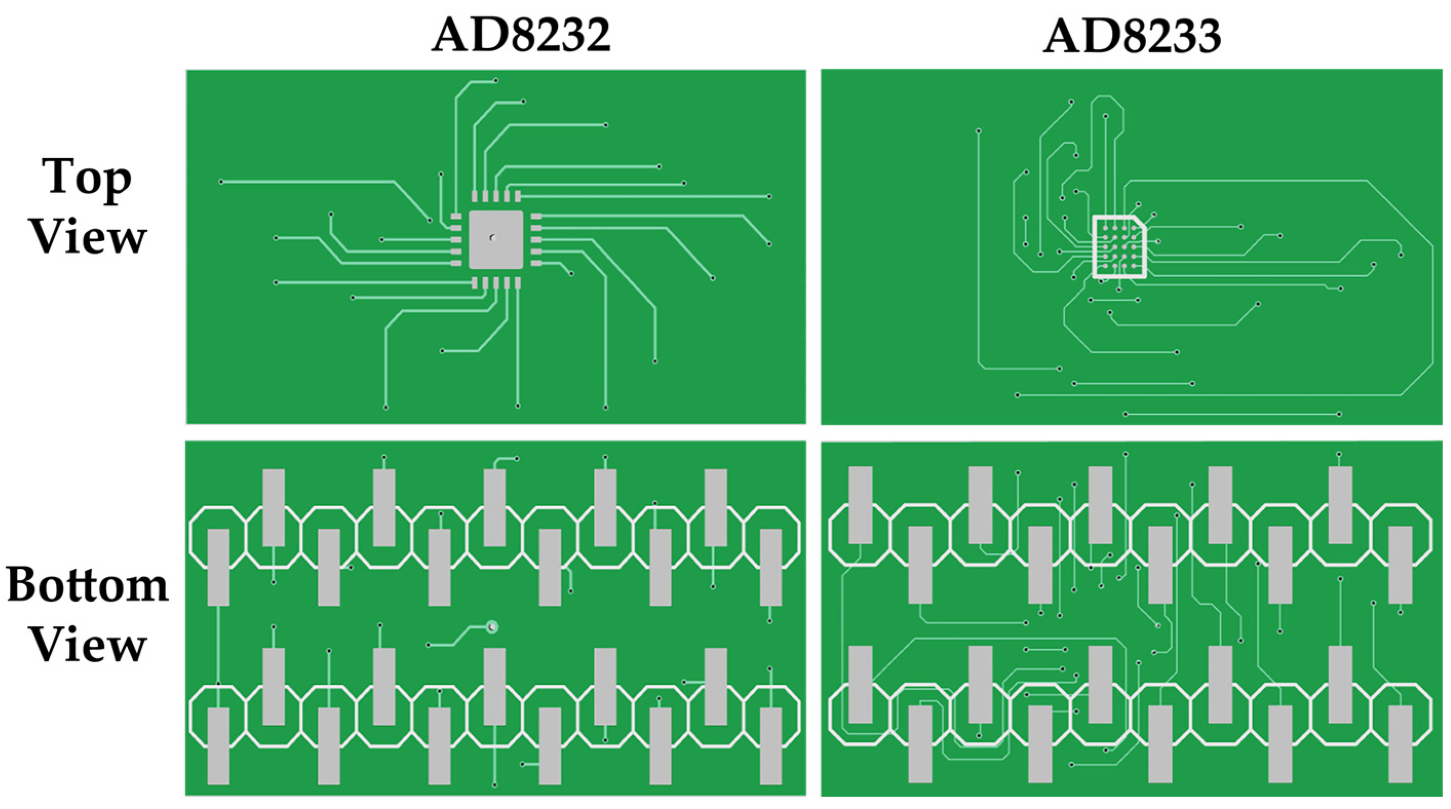
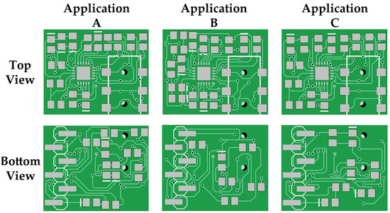
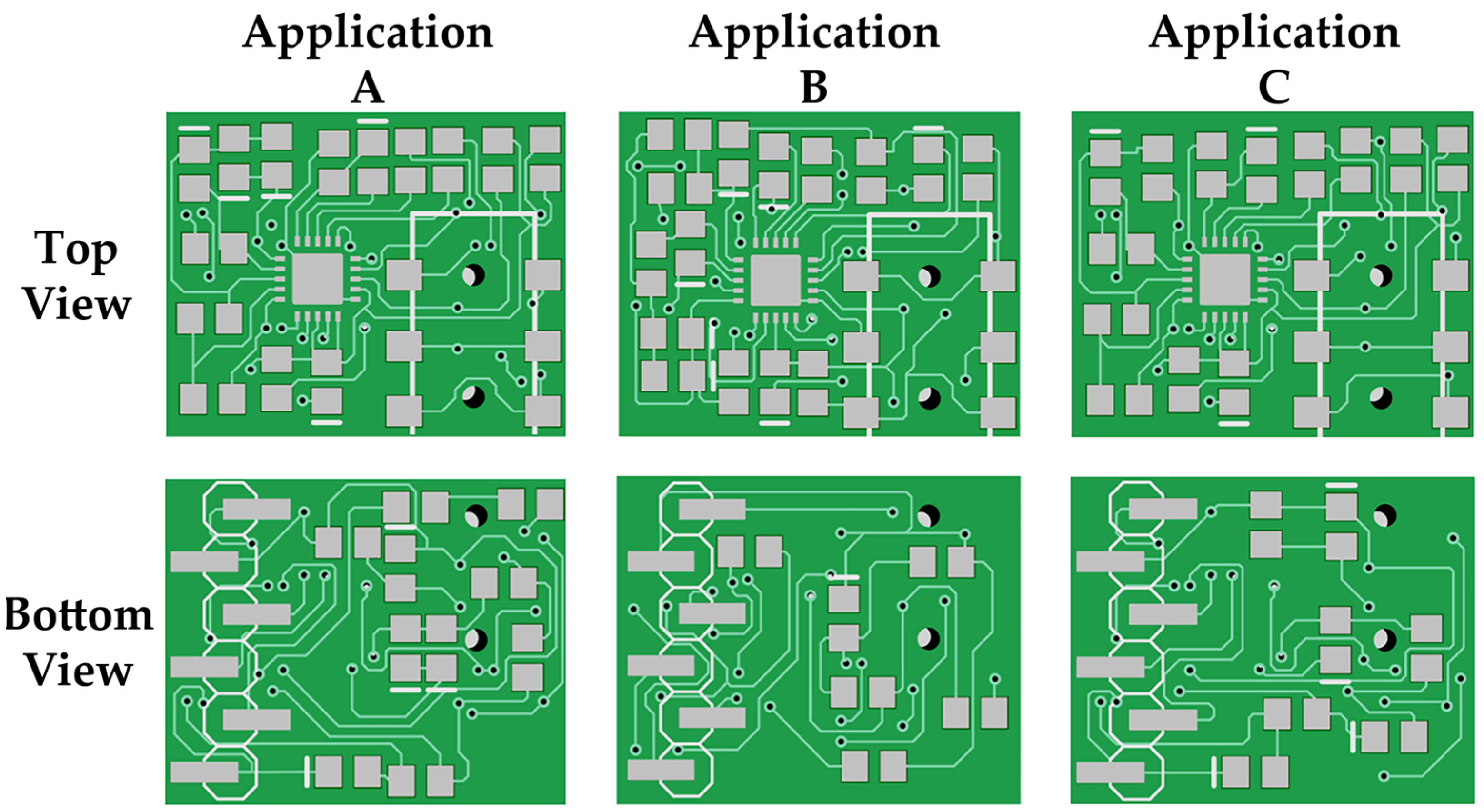
The schematics (A), (B), and (C) in Figure 1 presented above were assembled on a breadboard, and adapters that were made for the experiments were used for each of the AD823X chips in order to acquire signals using an analog discovery oscilloscope by Digilent (Pullman, WA, USA). Once the signals were ac-quired using the AD8232 chip adapter, it was replaced by the AD8233 chip adapter. Finally, after acquiring signals with both chips, a comparison was made of the quality of the signals acquired by both chips in the presented applications. Figure 2 shows the top and bottom views of each adapter for the AD8232 and AD8233 chips.
Figure 2.
AD8232 and AD8233 chip adapters to be implemented on the breadboard.
2.2. PCB Design for Each Application
Once the correct operation of each of the AD8232 chip applications on the breadboard had been tested, PCBs were designed for each application using Diptrace software version 5.1.0.3. Two PCB designs were created for the three applications. The first design “AFE board” includes only the AD8232 sensor circuit shown previously in Figure 1.
The second design “ECG Bluetooth board”, in addition to including the respective circuits from design I features an ATmega328p microcontroller, LM1117 by Texas Instruments (Dallas, TX, USA) and XC6206 by Torex Semiconductor (Singapore) voltage regulators that provide 5 V and 3.3 V power, respectively, when is supplied by an external voltage source between 5 V and 13.8 V to ensure the correct performance of the board, and finally, the CSR BC417 integrated circuit that enables Bluetooth data transmission, commonly used in HC-06 modules by Guangzhou HC Information Technology (Guangzhou, China).
Additionally, a third design was developed specifically for application C, this design named “Arduino Bluetooth ECG board” has the same components mentioned above, but also includes a Mini-B USB port, a CH340 integrated circuit by WCH (Jiangsu, China), and two extra analog pins, making it possible to reprogram the microcontroller and pins through the serial port, providing flexibility for the application of the board in different projects. Furthermore, the microcontrollers used in the designs ECG Bluetooth Board and Arduino Bluetooth ECG board are programmed to a baud rate of 115,200 bauds and to ac-quire the ECG signal at a sampling frequency of 250 Hz, following Nyquist’s theorem.
All boards components were mounted using a Yihua 862BD+ soldering station and a 6249S digital microscope. Once all components were mounted on each board, ECG signals were acquired using Einthoven’s DI lead, with electrodes placed on the right arm and left arm, and the reference electrode on the right leg; Once all the PCB designs were assembled, comparisons were made of the characteristics of each PCB, such as weight and dimensions, along with the quality of the signal acquired. The quality of the signals from the AFE board designs was compared, including the commercial AFE based on the SparkFun design, using a Digilent Discovery analog oscilloscope. Finally, wireless Bluetooth signals were acquired using the ECG Bluetooth board designs and the Arduino Bluetooth ECG board, and the signal quality of each was also compared.
3. Results
3.1. Circuits Assembled on Protoboard
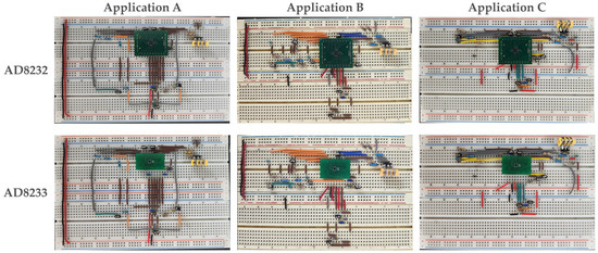
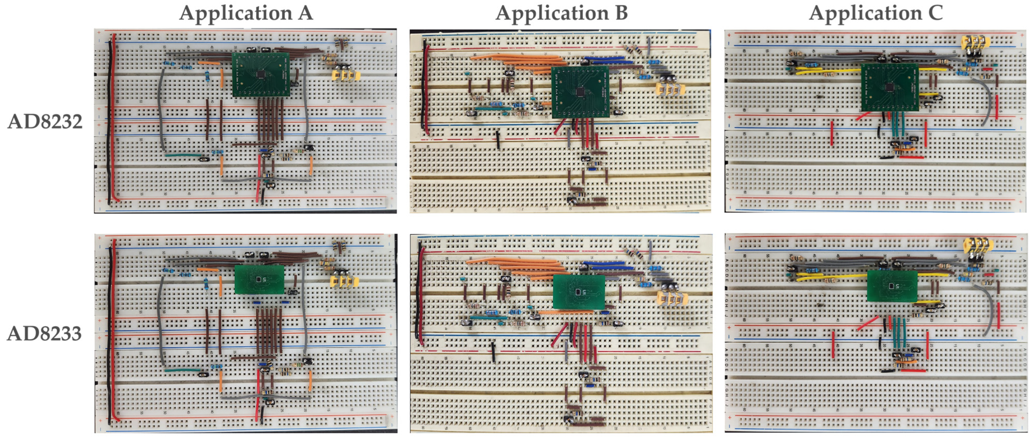
Each application mentioned previously in Section 2 was implemented on a breadboard. Figure 3 shows the assemblies corresponding to the three applications and the implementation of the AD8232 and AD8233 chip adapters.
Figure 3.
Circuits assembled on a breadboard using the AD8233 chip adapter for each application: (A) Cardiac monitor configuration; (B) Portable cardiac monitor with elimination of motion artifacts; (C) Exercise application (heart rate measured at the hands).
3.2. PCB Desing
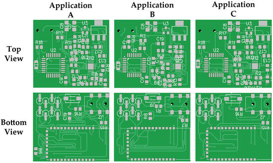
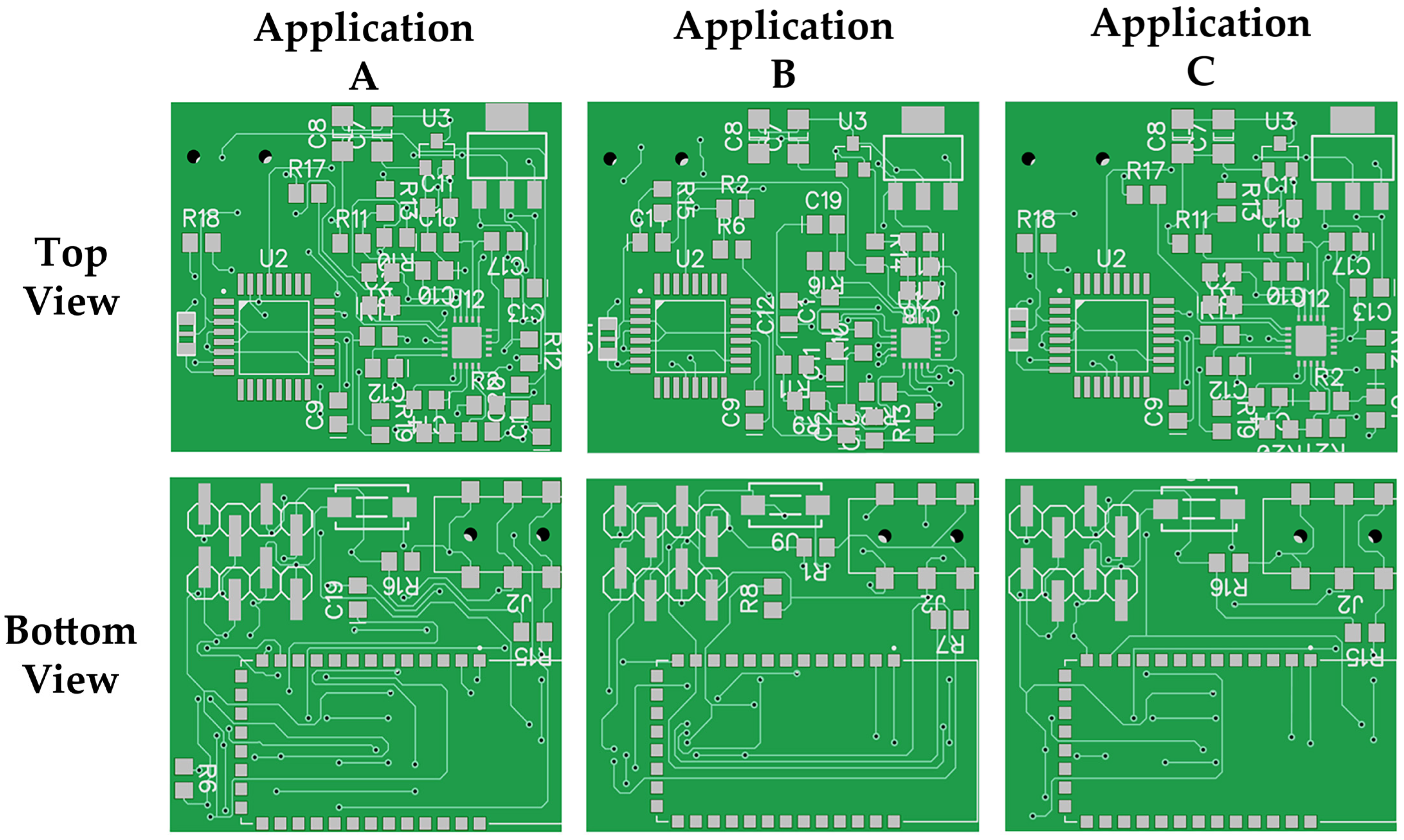
Figure 4 shows the AFE board design, which is the simplest and smallest design, it consists of the AD8232 chip, the PJ-313D jack connector, male pins for PCB connectivity, resistors, and capacitors. This design operates with a 3.3 V power supply and provides only an ECG analog signal.
Figure 4.
PCB AFE board designs for each application: (A) Cardiac monitor configuration application; (B) Portable cardiac monitor with elimination of motion artifacts and application; (C) Exercise application (heart rate measured at the hands).
Figure 5 shows the ECG Bluetooth board design, where the main components of this design are the ATmega328 microcontroller, which is commonly used in Arduino Uno and Arduino Nano boards, the CSR BC417143 chip that enables Bluetooth communication, an LM1117 voltage regulator that outputs 5 V to the board, which is the required voltage for its correct operation, and the XC6206P362MR 665K voltage regulator that outputs 3.3 V to the AD8232 chip in order for it to work correctly, in addition to the components mentioned previously in the AFE board design, namely a resonator and a RESET button for the microcontroller. This design provides an analog signal via a male pin, as well as a digitized signal that is transmitted via Bluetooth when the board is powered with between 5 V and 12 V.
Figure 5.
PCB ECG Bluetooth board designs for these applications: (A) Cardiac monitor configuration application; (B) Portable cardiac monitor with elimination of motion artifacts and application; (C) Exercise application (heart rate measured at the hands).
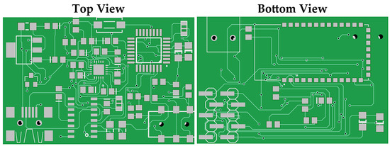
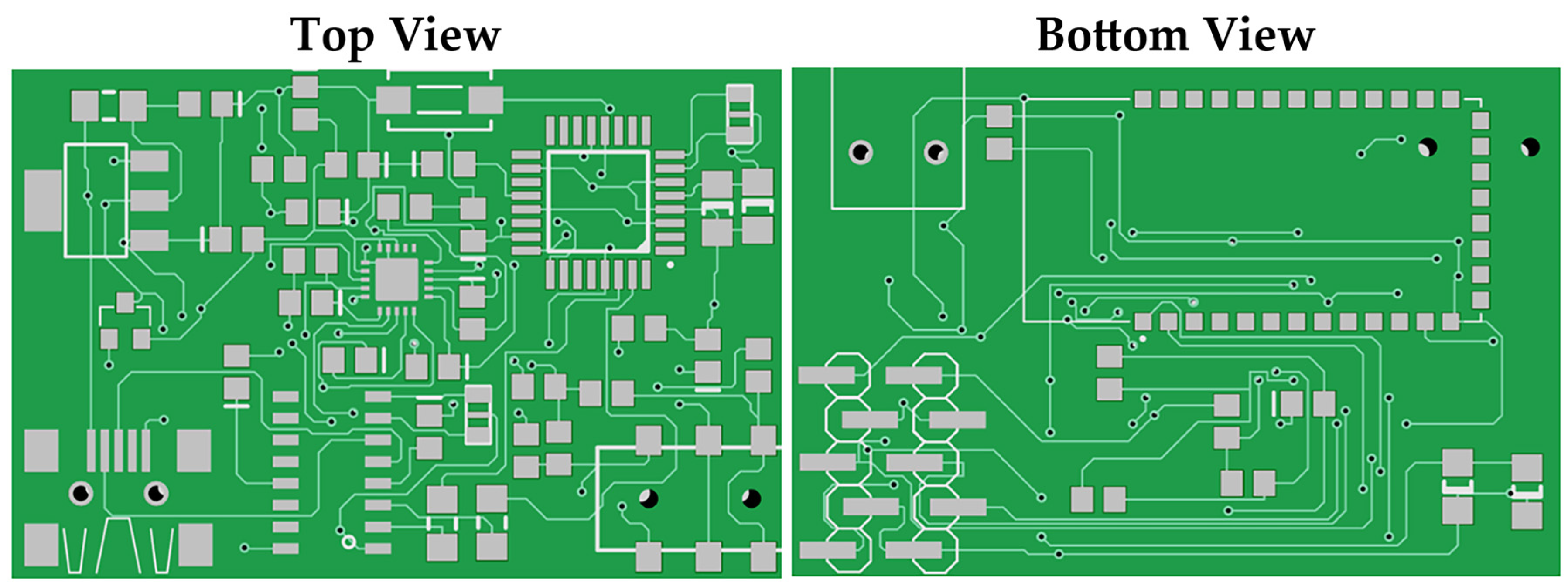
As mentioned in Section 2, the Arduino Bluetooth ECG board was designed only for the (B) Portable cardiac monitor with elimination of motion artifacts because this application has a wider area of application in the field of mHealth. For this reason, this configuration, in addition to having the components of the ECG Bluetooth board design, has a Mini-B USB port, with the CH340 chip with its respective resonator and two additional analog pins, since this design allows to reprogram the microcontroller and the three analog pins it contains. The design of this PCB is shown in Figure 6.
Figure 6.
PCB Arduino Bluetooth ECG board design for the (B) Portable cardiac monitor with elimination of motion artifacts.
Once all the PCBs were assembled, measurements were taken of the dimensions and weight of each design in each application, in addition to including the characteristics of the commercial PCB based on the SparkFun design. The measurements taken are shown in Table 1.
Table 1.
Physical dimensions and weight of every PCB.
3.3. Acquired Signals
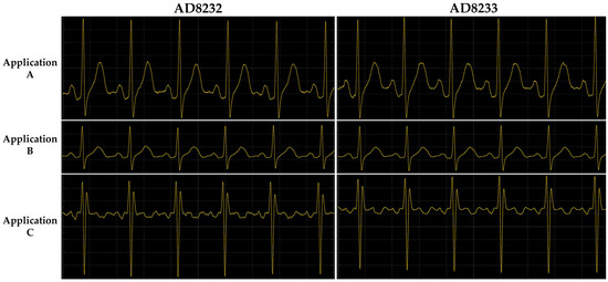
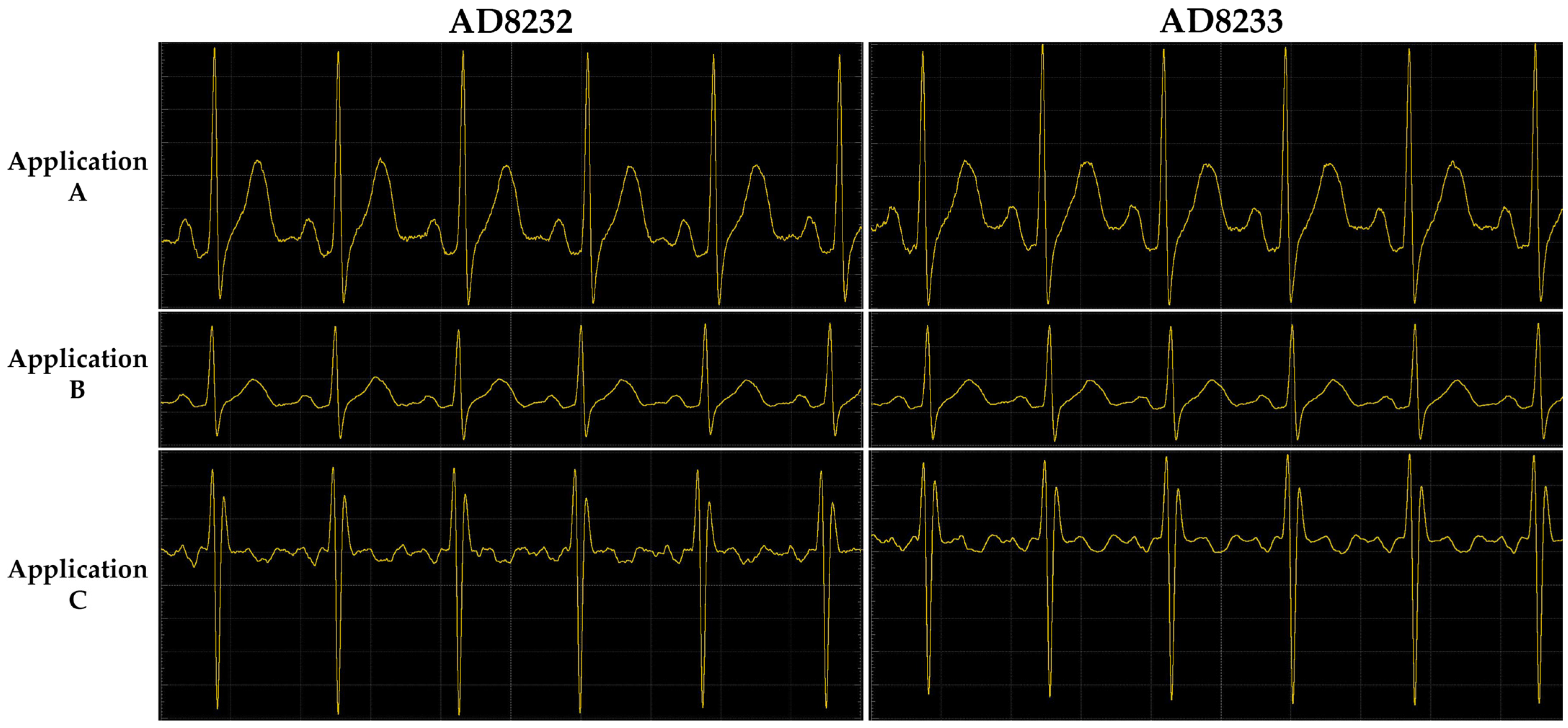
Figure 7 shows the signals acquired using the AD823X chip adapters in each of the breadboard applications presented. The signals were acquired using an analog discovery oscilloscope by Digilent at a scale of 100 mV/div and 500 ms/Div.
Figure 7.
Signals acquired on the breadboard using the AD8232 and AD8233 chip adapters for each application: (A) Cardiac monitor configuration, application; (B) Portable cardiac monitor with elimination of motion artifacts; (C) Exercise application (heart rate measured at the hands).
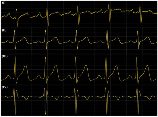
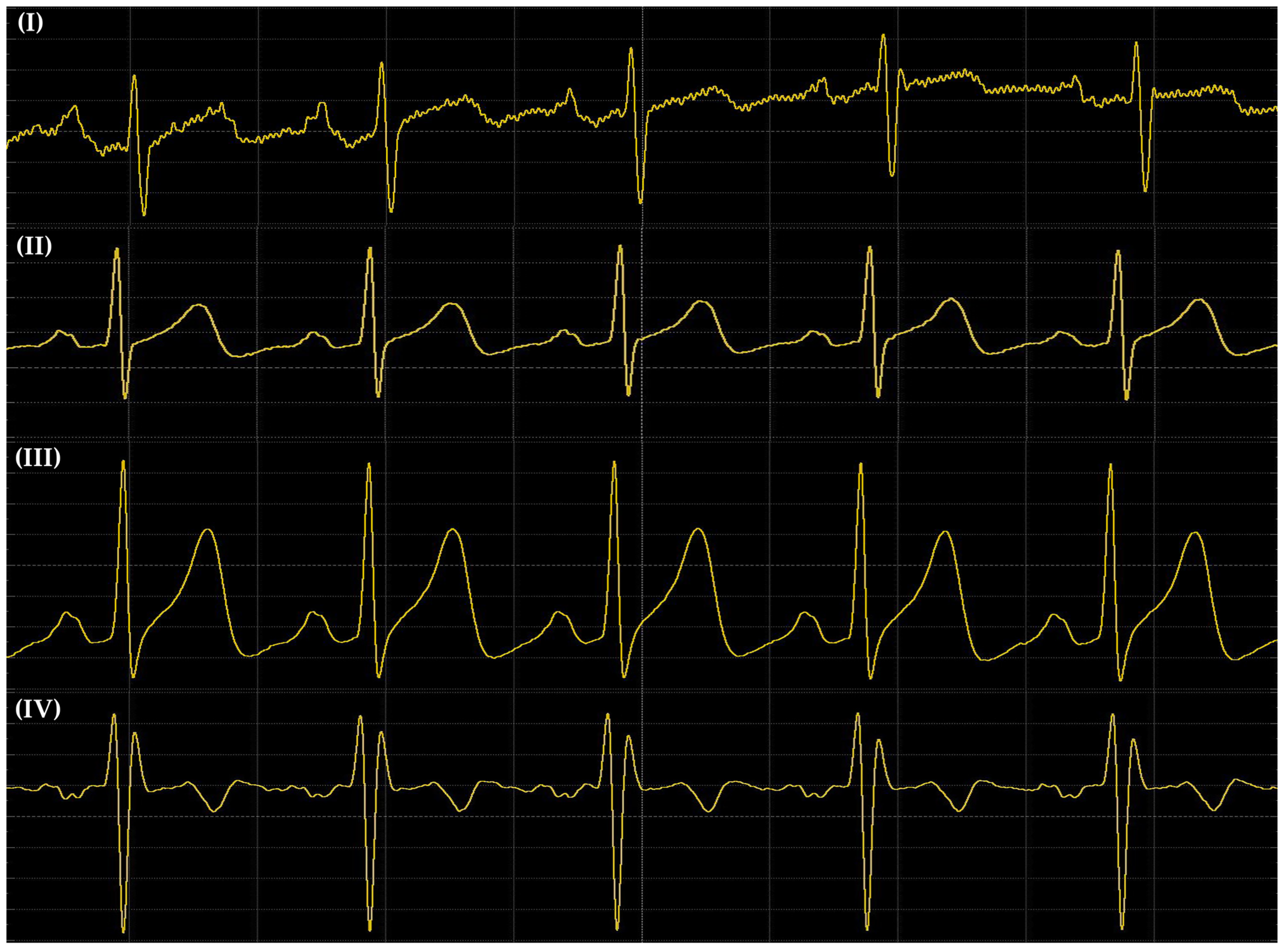
Figure 8 shows the signals acquired by the commercial AFE based on the SparkFun design and the PCBs with the AFE board design of each application, as mentioned in Section 2, the commercial AFE uses the Cardiac monitor configuration; for this reason signals (I) and (II) are located one below the other to facilitate their analysis. The signals were acquired using an analog discovery oscilloscope by Digilent at a scale of 100 mV/div and 500 ms/Div.
Figure 8.
Signals acquired using (I) the commercial board based on the SparkFun design, (II) the AFE board design with the Cardiac monitor configuration application, (III) the AFE board design with the Portable cardiac monitor with elimination of motion artifacts application, and (IV) the AFE board design with the Exercise application (heart rate measured at the hands).
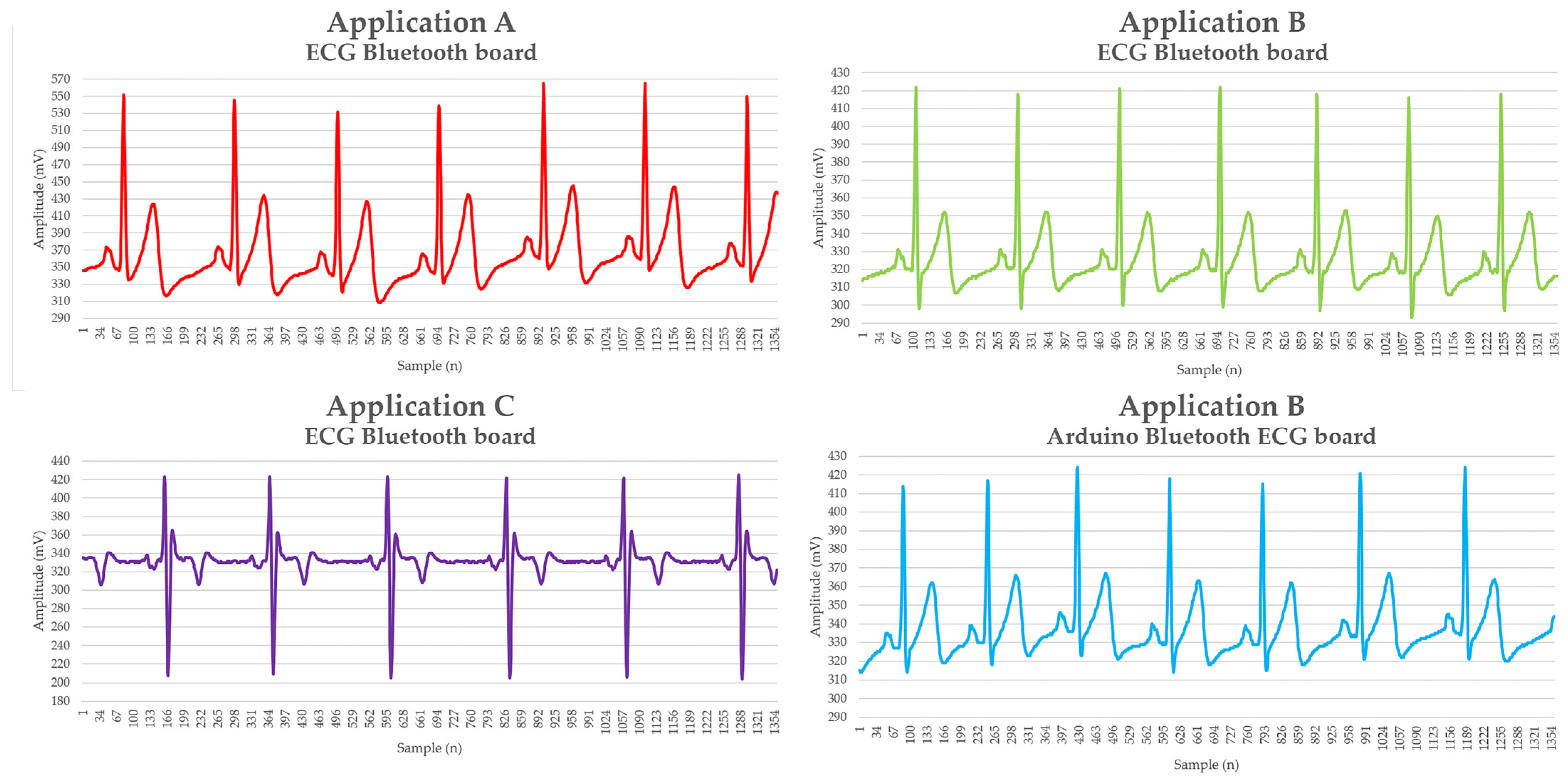
Finally, as shown in Figure 9, the signals from the ECG Bluetooth board and Arduino Bluetooth ECG board designs were acquired via Bluetooth. A DELL Inspiron 1500 personal computer was used for data acquisition and subsequently graphed.
Figure 9.
Signals acquired with designs ECG Bluetooth board and Arduino Bluetooth ECG board of the following applications: (A) Cardiac monitor configuration; (B) Portable cardiac monitor with elimination of motion artifacts; (C) Exercise application (heart rate measured at the hands).
4. Discussion
During breadboard testing, it was observed in Figure 7 that both circuits using the AD823X chips showed clear signals with an adequate morphology for an ECG, except for application C, which is used only to monitor heart rate. The AD8232 chip adequately fulfilled its signal acquisition purpose, but the acquired signal presented the presence of small noise signals, unlike the signals acquired with the AD8233 chip, which provided a signal with less noise. Despite this, both chips proved to be viable for the development of devices with mHealth applications. Among the main features that make the implementation of the AD8233 chip a better option than the AD8232 is its more stable baseline and lower noise, which translates into greater clarity when viewing the P, QRS, and T waves in applications A and B.
A significant improvement was made in application A on the AFE board with respect to the commercial SparkFun AFE board where, although they present the same configuration (cardiac monitor), the quality of the signal acquired with the AFE board is higher, as shown in Figure 8, as well as the reduction in the weight and dimensions, as shown in Table 1. These features that the AFE board provides (low weight and size), including the low operating power supply (3.3 V), represent some of the fundamental features that biosignal acquisition devices must present for mHealth applications.
The signals obtained from the breadboard were compared with those obtained from the assembled PCBs designs, revealing a high degree of similarity in the ECG signal morphology between them. What is characteristic of this comparison is that the signals provided by the PCB outperformed those from the breadboard due to the reduction in wiring-induced noise and the implementation of high-precision surface-mount components.
As presented in Table 1, the developed AFE board PCB with application A is 63.69% smaller than the commercial AFE based on the SparkFun design; in addition, the AFE board design weighs 1.679 g less, representing a weight reduction of 38.66% compared to the commercial one, in addition, a difference is seen in the quality of the acquired signals, with the commercial AFE signal presenting the highest amount of noise, which makes the PCB developed in this work a better option for the development of mHealth devices.
When comparing the signals obtained on the breadboard using the AD823X chip adapters with the signals acquired on the PCB using the AFE board designs, it is observed that both configurations present good signal quality, with better results in the PCB signal, as observed in Figure 7 and Figure 8.
The similarity in the quality of the acquired signals can be seen in Figure 8 and Figure 9, verifying that the signal quality of designs ECG Bluetooth board and Arduino Bluetooth ECG board was not affected by the extra components included in their respective design, demonstrating that their additional features do not compromise the quality of the acquired ECG signals.
A limitation that this work presents is that PCBs were only fabricated with the AD8232 chip and not with the AD8233 chip, since the AD8233 chip is smaller than the AD8232 chip and requires finer traces, which elevates the fabrication costs of the PCBs.
5. Conclusions
The performance of the AD8232 and AD8233 chips for the ECG signals acquisition is adequate and shows a low noise signal and fine morphology. The AD8233 chip offered the best performance, showing a signal with lower noise and better stability even when implemented on a breadboard compared to the signals acquired in PCB designs using the AD8232 chip.
The different PCB designs developed for different applications demonstrated promising performance, with reduced weight and size and improved signal quality compared to the commercial AFE based on the SparkFun design. This represents an alternative for implementation in projects that require compliance with the characteristics of the mHealth paradigm, presenting a reduction in size and weight, considering that these characteristics are very determinant when aiming to use these devices for mHealth applications. Additionally, the ATmega328 microcontroller performed adequately, allowing the digitization of the signals acquired by the AD8232 chip and their transmission.
In terms of manufacturing costs, manufacturing a PCB with the AD8232 chip is affordable, costing less than USD 1, compared to the cost of manufacturing a PCB using the AD8233 chip, which can cost more than USD 250.
As future work, it is proposed to design PCBs with the applications used in this work implementing the AD8233 chip in conjunction with precision components, which would facilitate obtaining signals with greater clarity and with reduced noise, together with the development of a specialized framework that helps eliminate ambient noise that the circuit may capture when acquiring ECG signals.
Author Contributions
Conceptualization, D.C.-G. and J.C.D.-T.; methodology, D.C.-G., J.C.D.-T., S.D.B.-Z., K.I.V.-P., E.A.-C. and O.E.B.; validation, D.C.-G. and J.P.G.-V.; formal analysis, J.C.D.-T. and D.C.-G.; investigation, D.C.-G., J.C.D.-T., and J.P.G.-V.; writing—original draft preparation, D.C.-G., J.C.D.-T., S.D.B.-Z., and K.I.V.-P.; writing—review and editing D.C.-G., J.C.D.-T., S.D.B.-Z., K.I.V.-P., and E.A.-C. visualization, O.E.B., R.L.A., and J.P.G.-V. supervision, D.C.-G.; funding acquisition, D.C.-G., J.P.G.-V., R.L.A., and O.E.B. All authors have read and agreed to the published version of the manuscript.
Funding
This research was funded by Secretaría de Ciencia, Humanidades, Tecnología e Innovación (SECIHTI) J.C.D.-T. Scholar fellowship CVU: 1353350, E.A.-C. Scholar fellowship CVU: 1055121, O.E.B. Scholar fellowship CVU: 1057559.
Institutional Review Board Statement
Not applicable.
Informed Consent Statement
Not applicable.
Data Availability Statement
The original data presented in the study are openly available in GitHub at https://github.com/ealtamira97/raw-ecg-signals.
Acknowledgments
We thank SECIHTI for the scholar fellowship of J.C.D.-T., E.A.-C., and O.E.B.
Conflicts of Interest
The authors declare no conflicts of interest.
References
- Cardiovascular Diseases (CVDs). Available online: https://www.who.int/news-room/fact-sheets/detail/cardiovascular-diseases-%28cvds%29 (accessed on 11 August 2025).
- Husain, K.; Mohd Zahid, M.S.; Ul Hassan, S.; Hasbullah, S.; Mandala, S. Advances of ECG Sensors from Hardware, Software and Format Interoperability Perspectives. Electronics 2021, 10, 105. [Google Scholar] [CrossRef] [Scilit]
- Qtaish, A.; Al-Shrouf, A. A Portable IoT-Cloud ECG Monitoring System for Healthcare. Int. J. Comput. Sci. Netw. Secur. 2022, 22, 269–275. [Google Scholar] [CrossRef]
- Siam, A.I.; El-Affendi, M.A.; Elazm, A.A.; El-Banby, G.M.; El-Bahnasawy, N.A.; El-Samie, F.E.A.; El-Latif, A.A.A. Portable and Real-Time IoT-Based Healthcare Monitoring System for Daily Medical Applications. IEEE Trans. Comput. Soc. Syst. 2023, 10, 1629–1641. [Google Scholar] [CrossRef] [Scilit]
- Prasanth, C.P.; Prakash, R.; Rufus, E.; Alex, Z.C. Design and Development of Cloud Based Mobile Health Monitoring System. In Proceedings of the 2021 Innovations in Power and Advanced Computing Technologies (i-PACT), Kuala Lumpur, Malaysia, 27 November 2021. [Google Scholar]
- AD8232_Heart_Rate_Monitor_v10. Available online: https://cdn.sparkfun.com/datasheets/Sensors/Biometric/AD8232_Heart_Rate_Monitor_v10.pdf (accessed on 11 August 2025).
- Single-Lead, Heart Rate Monitor Front End AD8232. Available online: https://www.analog.com/media/en/technical-documentation/data-sheets/ad8232.pdf (accessed on 11 August 2025).
- Cosoli, G.; Spinsante, S.; Scardulla, F.; D’Acquisto, L.; Scalise, L. Wireless ECG and Cardiac Monitoring Systems: State of the Art, Available Commercial Devices and Useful Electronic Components. Measurement 2021, 177, 109243. [Google Scholar] [CrossRef] [Scilit]
- Bravo-Zanoguera, M.; Cuevas-González, D.; Reyna, M.A.; García-Vázquez, J.P.; Avitia, R.L. Fabricating a Portable ECG Device Using AD823X Analog Front-End Microchips and Open-Source Development Validation. Sensors 2020, 20, 5962. [Google Scholar] [CrossRef] [Scilit] [PubMed]

Disclaimer/Publisher’s Note: The statements, opinions and data contained in all publications are solely those of the individual author(s) and contributor(s) and not of MDPI and/or the editor(s). MDPI and/or the editor(s) disclaim responsibility for any injury to people or property resulting from any ideas, methods, instructions or products referred to in the content. |
© 2025 by the authors. Licensee MDPI, Basel, Switzerland. This article is an open access article distributed under the terms and conditions of the Creative Commons Attribution (CC BY) license (https://creativecommons.org/licenses/by/4.0/).