


Abstract
Several approaches to producing lab-on-chip (LOC) devices have been developed in the last 20 years, including laser cutting of acrylic sheets and laminating them with adhesive films. While this route allows for rapid manufacture of devices, it cannot be scaled up beyond a couple of prototypes. For mass production of 3D LOC devices, injection molding is required, but mold manufacturing can be very costly. In this work we briefly report laser cutting parameters and lamination approaches, as well as 3D-printed injection mold inserts that allow one to produce LOC prototypes in facilities that have limited resources. This allows these facilities to transition from a couple of demonstrators to more than 100 devices in a short time and with limited costs.
1. Introduction
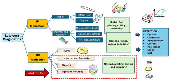
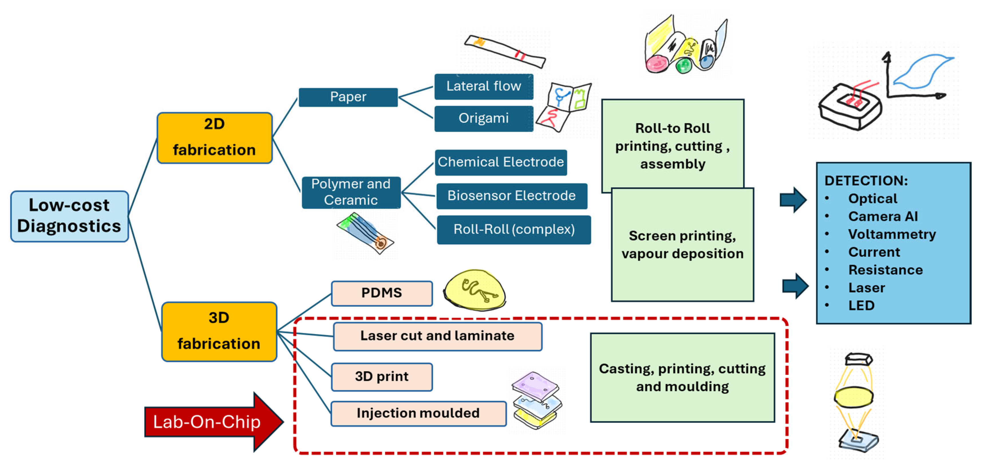
Low-cost medical diagnostics for point of care applications are increasingly becoming in demand, especially in developing countries, as these devices offer the opportunity to detect diseases in remote clinics and homes. Their development is high on the agenda of organizations concerned with health, as demonstrated by the World Health Organizations (WHO) REASSURED criteria that highlight the importance of real-time connectivity; ease of specimen collection; and affordable, sensitive, specific, user-friendly, rapid and robust, equipment-free or simple techniques which are deliverable to end-users to guide the implementation of low-cost diagnostics [1]. As shown in Figure 1, there are multiple technology platforms in low-cost diagnostics that address these needs, where 2D devices include paper-based approaches and electrode-based biosensors, while 3D devices, dominated by lab-on-chip (LOC), allow for increased versatility and complexity compared to paper-based devices [2]. An LOC is a device that integrates one or several laboratory functions on a single integrated circuit (commonly called a “chip”) of a few square centimeters that employs micro-sized channels, chambers and other functions [3]. An intermediary step to test a device before manufacturing costly injection molds is the use of laser cutting and lamination of acrylic sheets. Upon realizing that the device works in principle, another step towards low-cost injection molding is the 3D printing of mold inserts. This approach allows us to produce a prototype for less than USD 200, whereas the development of a steel injection mold can be expected to exceed USD 2000 [4]. Here we will discuss approaches to laser cutting devices and sealing approaches, as well as the progression to 3D-printed mold inserts.
Figure 1.
Approaches to low-cost diagnostic device manufacture.
1.1. Laser Cut and Laminated LOC
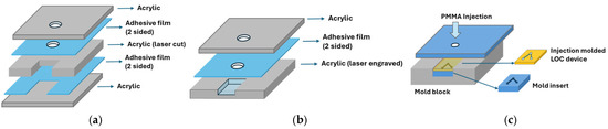
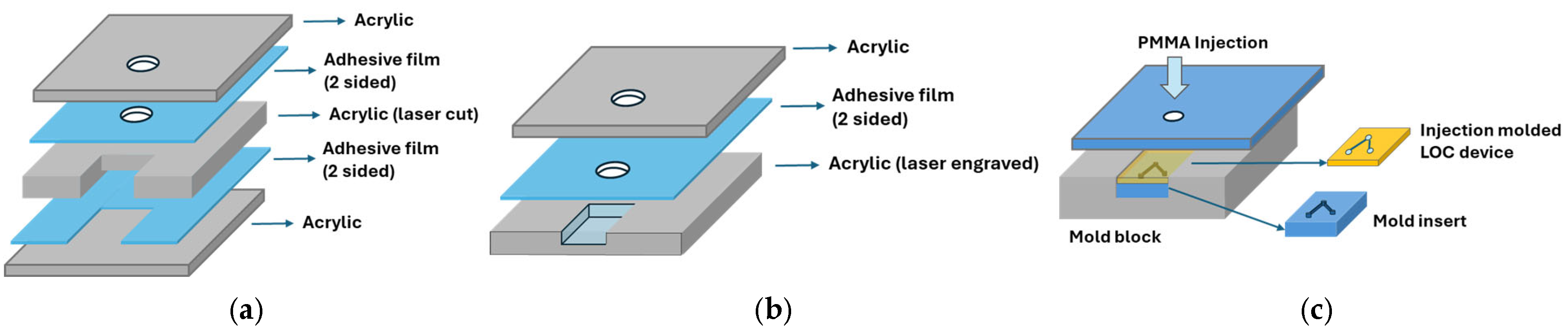
For laser cutting of LOC devices, the process must start with the design of a device layout using any available computer aided design (CAD) software, freeware such as Inkscape, (Inkscape is a free and open source software available at www.inkscape.org, accessed on 26 July 2024), or even Microsoft PowerPoint 2021 (Produced by Microsoft Corporation, Redmond, WA 98052-6399, United States) and transferring the coordinate instructions to the laser cutter. Liquid introduction and flow, valves, and the incorporation of sensors must be considered during the design. While electrode sensing elements are relatively easy to accommodate, optical sensors require a polymer that is very transparent. Polymethyl methacrylate (PMMA), with its high optical clarity, biocompatibility and chemical resistance, and electrical insulating properties, is thus an ideal polymer for LOC devices [5]. Finally, laser cutting and engraving must be accurate, and hence it is important to consider the laser beam alignment (shape), focus and power as well as cutting velocity. In the construction of a laser cut LOC device, there are several approaches that can be taken to assemble a unit, as shown in Figure 2a,b and described in the caption.
Figure 2.
(a) Acrylic sheet that contains the LOC features and is sandwiched between adhesive films and acrylic sheets or films. (b) Engraved acrylic sheet closed by acrylic sheet or film. (c) Injection mold block, shown with the mold insert (negative LOC protrusion), and LOC device (positive part with channels).
1.2. Injection Molded LOC
The fabrication of LOC devices through injection molding requires a mold and an injection molding machine. In the process, molten polymer is forced into the closed mold that contains a negative of the LOC part. As shown in Figure 2c, the mold block can be provided with a cavity that can receive a mold insert. As the insert is much smaller than the block, it is easier to manufacture and can even be 3D printed, which substantially reduces the production time and cost of the mold [4].
1.3. LOC Device Sealing
To complete LOC devices, the channels must be sealed. In Figure 2 we have suggested ways to achieve sealing by adhesive films. While this approach also works for injection molded LOC devices, ultrasonic and laser welding are robust alternatives [6]. For all sealing applications, the surface property of the acrylic part must be considered. For laser welding, the two surfaces must be very smooth and in contact, whereas adhesive film bonding, due to its somewhat elastic acrylic foam, allows for slightly imperfect surfaces. In addition, chemical or plasma treatment [7] and even roughening by fine-grained sandpaper can be considered for an improved bond.
2. Materials and Methods
2.1. Laser Cutting and Lamination
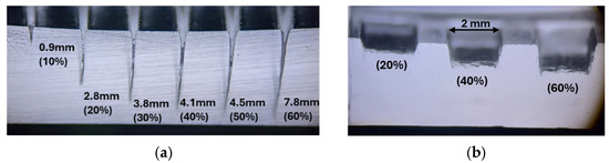
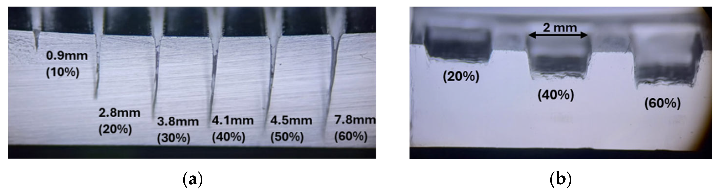
PLEXIGLAS® Clear 65 GT sheets of 1 mm thickness (Manufactured by Polyvantis, Evergreen Street Elandsfontein, Johannesburg South Africa) were cut with a 40 Watt Cron 3020 CO2 Laser Cutter (Manufactured by 3D Printing Factory (Pty) Ltd., Johannesburg, South Africa. To produce the different LOC devices the sheets were cut with and without 0.19 mm thick 3M GPT-020F double-sided acrylic adhesive tape (Manufactured by 3M Corporation, Saint Paul, Minnesota, United States). Laser alignment, cutting and engraving parameters were optimized by a set of cuts and engravings at different laser power settings, as indicated in Figure 3 and captured on a MEIJI Techno EMZ-10 Binocular Zoom Stereo Microscope (Manufactured by Meiji Techno, Chikumazawa, Miyoshimachi, Iruma-gun, Saitama, 354-0043, Japan).
Figure 3.
(a) Cross view of laser cuts and at increasing laser power (%) with the cut depth provided and (b) engraved pockets in acrylic sheet.
2.2. Injection Molding
Mold inserts were printed on a Formlabs Form +3 printer (Manufactured by Formlabs Corporation, Somerville, Massachusetts, USA), using their Rigid 10K Resin, and LOCs were molded with SUMIPEX MH PMMA granules (Manufactured by SUMIPEX Co., Ltd., Preakkasa Muang, Samutprakarn 10280, Thailand) on a BOY22M (Manufactured by Dr. Boy GmbH & Co. Neustadt-Fernthal, Germany) with a nozzle temperature of 240 °C. Flow properties on the LOC devices were measured using a Dolomite Mitos PPM010 flow system.
2.3. Adhesion Testing
For the adhesion testing, 16 mm wide adhesive strips were stuck to acrylic sheets at room temperature without heat treatment and pulled in a perpendicular direction using a DAYSENSOR DY920-B force gage (Manufactured by Dst (Shenzhen) Sensor Co., Ltd., Bengbu City, China) to determine the maximum adhesion. To compare the effect on adhesion properties, acrylic sheets were sanded with 600-grain sandpaper, treated with acetone for 20 s and plasma treated for 20 s.
3. Results
The results contribute to low-cost routes to LOC device fabrication.
3.1. Lamination Test
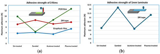
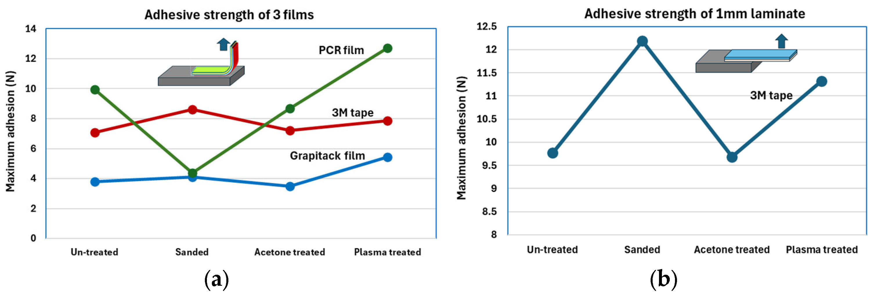
As shown in Figure 4a, PCR film offers the most efficient sealing layer and is also easy to apply. It does, however, not adhere to roughened surfaces. The 3M adhesive film adheres well to all surfaces and Graphitack film is the easiest to pull off. In Figure 4b, the adhesive strength of two acrylic sheets bonded by 3M adhesive film is shown. The result is like that of the flexible film and 3M tape, shown in Figure 4a, where adhesion to the sanded surface is marginally better.
Figure 4.
Adhesive delamination force of (a) films and (b) acrylic sheet on an acrylic surface subjected to different treatments.
3.2. Laser Cut and Laminated Magnetic Micro-Bead Separator
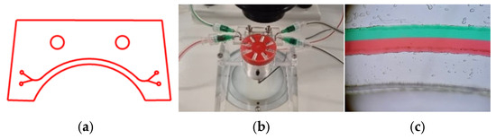
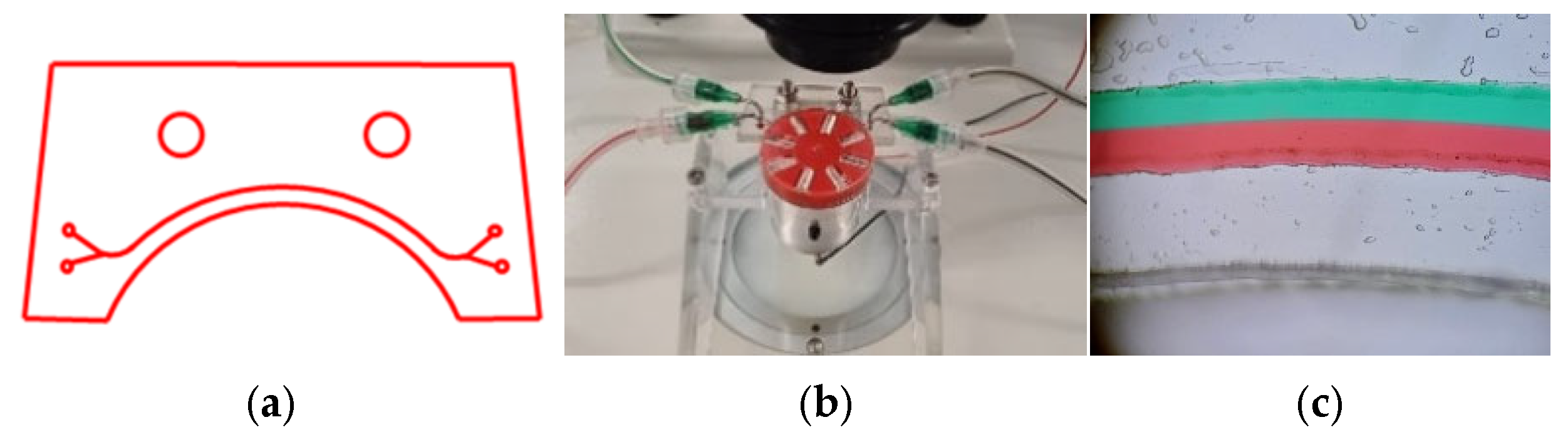
An example of a laser cut micro-fluidic is illustrated in Figure 5, starting with (a) simple vector drawings, (b) the assembled test device and (c) a microscope image of the perfect laminar flow achieved in this laser cut micro-bead separator device.
Figure 5.
Example of laser cut and laminated LOC approach. (a) Design; (b) Assembly under microscope; (c) Close-up image of the channel showing laminar flow.
3.3. Injection Molding
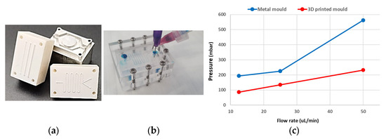
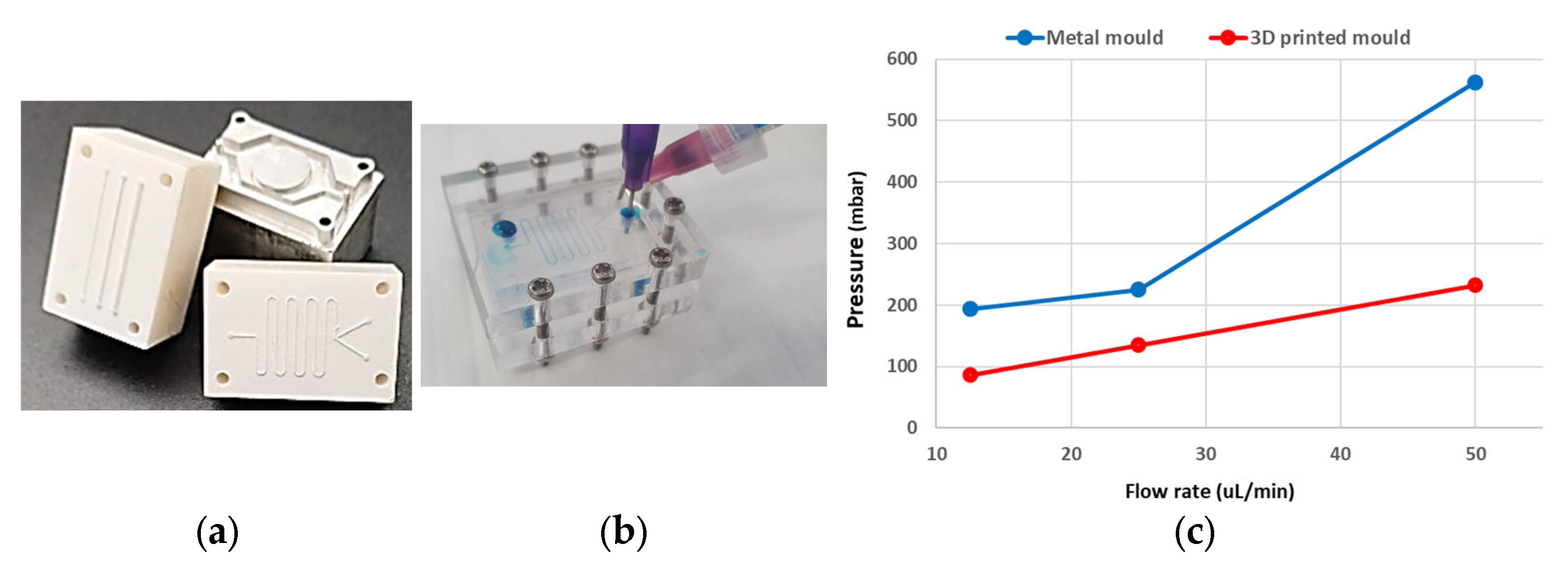
The 3D-printed injection molding inserts shown in Figure 6a were used to mold a PMMA LOC device, which is shown in Figure 6b. As illustrated in Figure 6c, the 3D-printed device allows for liquid flow at much lower pressures than the same device produced with an aluminum mold insert. This lower flow rate is due to an increased channel volume due to the resin of the 3D-printed mold having a lower heat transfer rate [8], which allows the part to shrink more before crystallization of the polymer.
Figure 6.
Example of a 3D-printed injection mold insert approach. (a) 3D printed mold inserts; (b) Injection molded device being tested; (c) Pressure and flow rates of the injection molded devices.
4. Conclusions
Laser cutting and lamination of acrylic sheets offers an easy, fast and low-cost route to develop LOC devices as intermediary steps to injection molding. However, the approach has limitations in complexity and the incorporation of functional elements. Injection molding on the other hand allows for increased complexity of devices and such devices can be mass produced. With the printing of 3D mold inserts, injection molding can also offer a low-cost route to prototype production. The heat transfer properties of the printed material must be taken into consideration when using this approach. Finally, PCR film offers a good sealing layer for these low-cost LOC devices.
Author Contributions
Conceptualization, M.S., methodology, M.S. and M.K., validation, M.S., V.M., M.K. and E.M.; formal analysis, M.S., V.M. and E.M.; resources, M.S.; M.K., V.M. and E.M., writing—original draft preparation, M.S.; review and editing, V.M. and M.S.; funding acquisition, M.S. All authors have read and agreed to the published version of the manuscript.
Funding
This research is part of a capability development project funded by the South African Department of Science, Technology and Innovation.
Institutional Review Board Statement
Not applicable.
Informed Consent Statement
Not applicable.
Data Availability Statement
The raw data supporting the conclusions of this article will be made available by the authors on request.
Conflicts of Interest
All authors were employed by Council for Scientific and Industrial Research and declare that the research was conducted in the absence of any commercial or financial relationships that could be construed as a potential conflict of interest.
References
- Land, K.J.; Boeras, D.I.; Chen, X.-S.; Ramsay, A.R.; Peeling, R.W. REASSURED diagnostics to inform disease control strategies, strengthen health systems and improve patient outcomes. Nat. Microbiol. 2019, 4, 46–54. [Google Scholar] [CrossRef] [Scilit] [PubMed]
- Omidfar, K.; Riahi, F.; Kashanian, S. Lateral Flow Assay: A Summary of Recent Progress for Improving Assay Performance. Biosensors 2023, 13, 837. [Google Scholar] [CrossRef] [Scilit] [PubMed]
- Wartmann, D.; Rothbauer, M.; Kuten Pella, O.; Barresi, C.; Visus, C.; Felzmann, T.; Peter, E. Automated, Miniaturized, and Integrated Quality Control-on-Chip (QC-on-a-Chip) for Cell-Based Cancer Therapy Applications. Front. Mater. 2015, 2, 60. [Google Scholar] [CrossRef] [Scilit]
- Formlabs. Available online: https://formlabs.com/blog/injection-molding-cost/ (accessed on 26 July 2024).
- Romoli, L.; Tantussi, G.; Dini, G. Experimental approach to the laser machining of PMMA substrates for the fabrication of microfluidic devices. Opt. Lasers Eng. 2011, 49, 419–427. [Google Scholar] [CrossRef] [Scilit]
- Kistrup, K.; Poulsen, C.E.; Hansen, M.; Wolff, A. Ultrasonic welding for fast bonding of self-aligned structures in lab-on-a-chip systems. Lab Chip. 2015, 15, 1998–2001. [Google Scholar] [CrossRef] [Scilit] [PubMed]
- Yablokov, M.; Kechek’yan, A.; Bazhenov, S.; Gil’man, A.; Piskarev, M.; Kuznetsov, A. Adhesive properties of plasma-modified polytetrafluoroethylene films. High Energy Chem. 2009, 43, 512–515. [Google Scholar] [CrossRef] [Scilit]
- Burlaga, B.; Kroma, A.; Poszwa, P.; Kłosowiak, R.; Popielarski, P.; Strek, T. Heat Transfer Analysis of 3D Printed Wax Injection Mold Used in Investment Casting. Materials 2022, 15, 6545. [Google Scholar] [CrossRef] [Scilit] [PubMed]
Disclaimer/Publisher’s Note: The statements, opinions and data contained in all publications are solely those of the individual author(s) and contributor(s) and not of MDPI and/or the editor(s). MDPI and/or the editor(s) disclaim responsibility for any injury to people or property resulting from any ideas, methods, instructions or products referred to in the content. |
© 2025 by the authors. Licensee MDPI, Basel, Switzerland. This article is an open access article distributed under the terms and conditions of the Creative Commons Attribution (CC BY) license (https://creativecommons.org/licenses/by/4.0/).