


Abstract
Sustainable automotive power systems require low-carbon fuels that retain the advantages of conventional internal combustion engines. The current study conducted experiments to examine the combined influence of ethanol injection timing (EIT) and hydrogen energy share (HES) in a parallel dual-direct-injection spark-ignition engine, with direct injection of ethanol and hydrogen at 120 and 10 bar, respectively. Hydrogen injection timing was set at 26 °CA ATDC, EIT varied from 80 °CA ATDC to 160 °CA ATDC, and hydrogen injection ratio (HES) varied from 0% to 20%. For the highest brake thermal efficiency (25.381%), the results indicated 15% HES and 130 °CA EIT, which were 1.94% better than neat ethanol. Under these conditions, the CA10 decreased by 10.8%, and the peak cylinder pressure and peak cylinder temperature increased by 6.36% and 2.60%, respectively. At 20% HES, CA10–90 decreased by 14.61%, peak heat-release rate increased by 11.14%, and CoVIMEP decreased by 16.35%. When 15% HES and 130 °CA EIT are used, the levels of CO, HC, and CO2 emissions were reduced by 16.05%, 16.36%, and 9.89%, respectively, despite an increase of 19.32% in the levels of NOx emissions. It can be observed that injecting ethanol using hydrogen energy shares will improve the above factors.
1. Introduction
Global decarbonization efforts are more influential in the automobile sector, which is largely fueled by hydrocarbon-based fossil fuels. The non-renewability of these primary energy sources promotes energy insecurity and a fiscal deficit in an importing nation. Simultaneously, combustion, the only means of extracting energy from these sources for automotive prime movers, produces several harmful emissions [1]. These concerns have compelled governments across the globe to consider alternative solutions, motivating the scientific fraternity to look for them. Various emission norms, the promotion of green fuels, and research incentives are among the few policies adopted by many nations in that area. Among the alternatives searched, agricultural products, bioproducts, and hydrogen are prominent energy sources [2,3]. However, many of these are based on hydrocarbons with long carbon-hydrogen chains, which may be as challenging as conventional sources, particularly in terms of emissions. Therefore, low-carbon or non-carbon fuels offer the possibility of a complete replacement of conventional sources in a sustainable way. Among such low-carbon fuels, ethanol has recently gained significant popularity due to its low carbon-to-hydrogen ratio, a widely available network, and the flexibility of its production methods and feedstocks [4]. Ethanol can be produced from many agricultural products, such as sugarcane, rice, and corn, as well as from biowastes. It already has large-scale distillation and transportation infrastructure that may help make fuel availability more flexible and easier. Based on such facts, several nations have already rolled out policies related to ethanol fuel; among others, India and Brazil are vocal nations of ethanol branding. India has a mandatory 20% ethanol blending policy in gasoline, targeting a rise to 30% in the coming years, while Brazil has increased the limit to 32% ethanol in commercial gasoline [5,6,7,8]. Similar norms are observed across multiple nations owing to ethanol’s fuel properties.
The popularity of ethanol is mainly due to its flexibility in production and its influential fuel properties. The much higher octane number and autoignition temperature compared to gasoline allow greater resistance to knock. Hence, enables the engine to run at higher compression ratios, higher advance rates, and higher loads, thereby increasing thermal efficiency and compactness. Studies show that it exhibits relatively high laminar burning speed under appropriate conditions, resulting in increased flame speed and energy release [9]. Moreover, its high oxygen content (about 34.7% by weight) enables more efficient burning of rich fuel. As a rule, the use of ethanol in gasoline reduces the emission of CO and unburned hydrocarbons. In addition, it can reduce particulate formation due to the lower levels of aromatics and carbonaceous compounds in gasoline [10]. This effect is especially useful when the fuel is not homogeneous but contains local regions of richness; otherwise, incomplete combustion would occur. Ethanol has a higher latent heat than gasoline, which makes it easier to cool the charge gas, potentially increasing its density and improving volumetric efficiency (ηvol). The cooling effect, when applied in a suitably controlled direct-injection SI engine, can also help prevent knocking [11]. Ethanol has also been shown to have desirable blending properties from a fuel standpoint: recent research indicates that ethanol blending can significantly boost gasoline octane (while altering its volatility characteristics), thereby enabling the formulation of higher-octane gasoline for advanced SI combustion systems. In addition, it has the potential to enable important decarbonization of the fossil-carbon lifecycle when produced sustainably [12]. Ethanol is particularly promising for advanced DISI concepts, where its octane rating, charge cooling, and oxygenation benefits can be exploited through optimised combustion control.
Ethanol-gasoline mixtures were analysed by Sathish Kumar et al. [13] in a DISI engine, and it was found that as the ethanol percentage increased, BTE increased from 18.27% to 27.31%. An increase in ethanol percentage also increased cylinder pressure and HRR, along with an earlier onset of these parameters, thus indicating the significance of proper fuel and engine tuning. Kim et al. [14] experimentally characterised ethanol-gasoline combustion using crank-angle-resolved flame luminosity in a GDI engine. 10–50% ethanol mixtures were studied in stoichiometric, lean homogeneous, and lean stratified combustion conditions. It was found that an ethanol mixture affects the mixture’s quality, flame development, and particulate formation. The effects of the timing and pressure of ethanol direct injection (DI) in a dual-fuel SI engine using gasoline PFI and ethanol DI were investigated systematically by Li et al. [15]. Postponing the timing of ethanol injection from −340 °CA to −300 °CA resulted in a significant reduction in particulate number and mass, whereas elevating the injection pressure from 5.5 to 18 MPa improved secondary atomisation and the mixing process. As a result, the particulate number and mass were decreased by 51.15% and 22.64%, respectively. Zhao et al. [16] analysed the effect of oxyhydrogen injection in a ternary-fuel SI engine fuelled individually with ethanol, gasoline and oxyhydrogen. Injecting oxyhydrogen increased the maximum cylinder pressure and IMEP, shortened the flame development period and combustion duration, but also caused NOx formation. Ethanol DI partially inhibited NOx formation and achieved better mixture stratification than gasoline DI. No less important is the combustion synergy between ethanol and oxyhydrogen, which is also reported. This synergy results from oxyhydrogen’s very low ignition energy, which increases the likelihood of fire initiation and enhances combustion. Ethanol DI helped in NOx suppression due to oxyhydrogen. This is evidence of the potential advantage of using the contrasting physical and chemical properties of hydrogen-based fuels and ethanol through independent control of their supply. Sathish Kumar et al. [17] established optimal control maps for ethanol-gasoline DISI operation by considering the ethanol blend ratio, spark timing, injection timing, and injection pressure. Through this method, a maximum brake thermal efficiency (BTE) of 24.04% was achieved in E30. It has been shown that the optimum injection and ignition requirements depend on the ethanol concentration in the fuel.
The effects of ethanol quantity, compression ratio, and water content in the GDI engine operating at partial loads have been studied by Voris et al. [18]. An increase in ethanol percentage enhanced stability, while an increase in the compression ratio decreased stability and combustion time. The addition of water reduced NOx emissions by 20% and 40% at water contents of 10% and 20%, respectively; however, excessive dilution could negatively affect the CoV of IMEP and HC oxidation. Hong et al. [19] conducted lean-burn experiments in an ethanol-fuelled HD SI engine and demonstrated the high flexibility in combustion timing due to ethanol’s knock resistance. An increase in the excess air coefficient from 1.0 to 1.8 resulted in an advance of CA50 from 22.3 °CA to 12.4 °CA ATDC and increased the indicated thermal efficiency by 6.9 percentage points. The influence of low-temperature heat release and laminar flame speed on gasoline-ethanol SI engine combustion was studied by Isobe et al. [20]. They observed that laminar flame speed increases with increasing ethanol proportion in the late stages of combustion for engines with high compression ratios. The effect of low-temperature heat release on the temperature and composition of the unburnt charge has also been observed. Nour et al. [21] investigated the combustion of the ABE blend with gasoline under GDI conditions and demonstrated the importance of spray formation and injection in the use of alcohol fuels. In the simulated cold-start regime, the use of ABE blends reduced peak cylinder pressure (Pmax) and peak heat release rate (HRRmax) by 13.4% and 27.3%, respectively. Thus, the authors pointed out that the use of alcohol fuels should be accompanied by optimised and developed injection strategies to maintain low emissions while not impairing the combustion process. Perrone et al. [22] showed the possibility of using a converted heavy-duty SI engine with neat ethanol as fuel and optimised spark timing parameters. The efficiency of the ethanol operation mode was 32% in the experiment and 37.5% after the optimisation. Despite the high-octane number and oxygenated properties of ethanol, there are drawbacks to its use in direct-injection SI engines due to its high latent heat of vaporization, low heating value, and poor volatility, which can hamper evaporation and mixing under unfavourable conditions [23]. The strong evaporative cooling effect of ethanol reduces the charge temperature locally, leading to a slow burning rate and unstable combustion, especially at cold start and low loads [24]. Also, ethanol has a lower energy density, which means a larger amount of fuel must be injected into the combustion chamber, and improper atomization and timing of fuel injection may cause wall wetting and incomplete burning [25]. Therefore, a combustion promoter is necessary to increase the speed of flame propagation, and hydrogen is an ideal choice for this purpose [26].
Hydrogen’s increased flame velocity and reduced ignition energy and flammability limit can increase the combustion rate of ethanol, especially when combustion is lean. Tian et al. [27] numerically examined ethanol-hydrogen mixtures and found that at 1500 rpm, 10% hydrogen resulted in improvements of 24.6% in BSFC and 5.02% in brake torque, and reductions in HC, CO, and CO2. Suresh and Porpatham [28] conducted an experimental study on the hydrogen supplementation of ethanol-gasoline mixtures under lean operating conditions. Hydrogen enrichment boosted brake performance, increased BTE at lower equivalence ratios, and extended the lean operating limit to 0.47. Increased combustion rate further improved heat release, cycle-to-cycle variations, and HC emissions. Zhen et al. [29] numerically compared methanol/hydrogen, ethanol/hydrogen, and methane/hydrogen blends in an SI engine with a compression ratio of 17.5. Hydrogen addition extended ignition delay and combustion duration while reducing CO, CO2, and HC emissions. Methanol/hydrogen produced higher power, whereas methane/hydrogen exhibited lower brake specific fuel consumption under comparable conditions. Ayad et al. [30] studied the effect of hydrogen as a fuel supplement on an ethanol-fuelled engine operating under lean conditions. Fuel conversion efficiency was boosted, and CO and HC were reduced, but brake power and NOx did not decrease with the addition of hydrogen up to 2% when 10–30% excess air was added. To improve fuel conversion efficiency while maintaining baseline power, 6% hydrogen was required at 40% excess air. Amaral et al. [31] used ethanol as the main fuel and supplied the hydrogen-rich gaseous mixture via fumigation. In ethanol combustion, hydrogen addition increased the combustion rate and decreased specific fuel consumption when combustion was properly controlled. The authors attributed the enhanced burning process to hydrogen’s low ignition energy, high flame velocity, and high adiabatic flame temperature. Purayil et al. [32] reported that as hydrogen was progressively increased, Pmax and HRR increased because combustion occurred in a shorter time and heat release was concentrated towards TDC due to hydrogen’s higher laminar flame speed. The highest cylinder pressure at 4 °CA BTDC ignition with the highest hydrogen flow was 33.87 bar for E50. Inbanaathan et al. [33] tested hydrogen assistance by varying engine speed and the duration of hydrogen injection in ethanol-gasoline flexible fuels. Of the conditions tested, E30 with hydrogen addition (3 ms) showed superior combustion, performance, and emission properties. Hydrogen addition increased combustion intensity but also led to higher NOx emissions due to the higher temperatures associated with more complete combustion. Oral [34] investigated the effects of H2/O2 supplementation to an ethanol-gasoline mixture. Torque and power increased by 5.8% and 5.66%, respectively, when H2/O2 was added to G5E, while the specific fuel consumption decreased by 2.82%. The CO and HC levels dropped by 24.47% and 16.75% relative to the gasoline level, respectively, but the higher combustion temperature increased NOx. Marwaha and Subramanian [35] presented comparative evidence for the complementary combustion behaviour of their respective compounds. BTE rose by 1.2% with ethanol and 25.9% with hydrogen compared to gasoline. The significant increase in hydrogen efficiency was attributed to its higher laminar burning velocity, which led to faster energy release. Suresh et al. [35] also looked at hydrogen-assisted ethanol-gasoline combustion testing and machine-learning models. The primary role of hydrogen as a combustion-rate promoter was to increase lean flammability and to decrease combustion time. There was higher combustion stability at a 5% hydrogen content in the mixture near the lean-misfire limit, whereas too-rich mixtures were associated with spark retardation and decreased thermal efficiency. Recently, Yang et al. [36] studied ethanol-hydrogen operation under controlled hydrogen-injection pressure and split-injection ratio. The torque increased by 3.36%, the CoV reduced by 10.06%, and the HC reduced by 9.08% at 7 MPa and a secondary injection ratio of 1:2. The improvements in maximum BTE (by 4.83%) as well as the significant reductions in CA0-10 and CA10-90 were due to better hydrogen distribution and ignition. The direct injection of hydrogen offers more control over the amount, timing, and spatial distribution of hydrogen while maintaining the incoming air-ethanol charge.
The introduction of hydrogen directly into the combustion chamber via direct injection, with minimal effects on ηvol, no air displacement, and no backfiring, is a significant advantage of this technology and has been mainly associated with hydrogen direct injection (HDI) in the case of alcohol-fueled SI engines [37,38,39]. The advantage of direct injection is that the amount of injected hydrogen, as well as the injection timing, jet penetration, and spatial distribution, can be controlled, thereby allowing the mixture around the spark plug to be controlled independently of the main charge of alcohol and air [40,41,42]. Early injection provides adequate time for diffusion, resulting in a well-mixed fuel with low levels of stratification. On the other hand, late injection increases stratification; hence, the timing of the injection is a significant parameter to consider [43,44]. Optical investigations also show that the hydrogen jet’s penetration, spreading, turbulent interaction, and mixture dispersion are significantly influenced by the timing of the injection, and that when ignition occurs near the end of injection, the locally richer region of hydrogen near the spark plug will ignite quickly [45]. This is especially beneficial for ethanol, with its high latent heat of vaporisation and associated charge cooling, which can slow the combustion rate when the mixture is lean. Increasing the H2 fraction from 0% to 20%, directly injected hydrogen (HDI) into the hydrous-ethanol SI engine resulted in a reduction of the flame-development and rapid-combustion periods by 58.6% and 25.8%, respectively, an increase of IMEP by 4.16%, and a decrease of CoVIMEP by 54.09%, which indicates the strong combustion-promoting effect of the direct injection of hydrogen to the SI engine [46]. The use of hydrogen enrichment in the alcohol based investigations reported similar findings: the availability of OH radicals is increased, combustion duration is reduced, and the allowable range of injection is expanded, due to fuel-air mixing caused by the higher hydrogen content [47]; however, the HRR of the alcohol is increased, and combustion stability is improved, despite the poor alcohol evaporation and atomization properties in the case of HDI in n-butanol operation [48,49]. Injection pressure and injection scheduling also affect the benefits of HDI. Increased jet pressure will enhance jet penetration and mixture preparation, while very retarded injection can increase local mixture stratification and cyclic variation [50,51]. The split injection method further allows for greater control by applying an early injection to create an appropriate background hydrogen mixture and a later injection to add hydrogen closer to the flame kernel, thereby ensuring sufficient flame propagation and rapid flame kernel development [52]. Hydrogen enrichment or stratification has also been shown to promote early combustion and enhance stability under highly diluted conditions in studies of other low-reactivity, carbon-free, and alcohol fuels [53]. The high flame speed and high reaction temperature of hydrogen, however, can result in increased NOx emissions and greater susceptibility to abnormal combustion, especially at higher mixture strength and load [54]. Hence, along with HDI, lean operation, EGR, and water injection are investigated to control temperature, NOx, pre-ignition, and knock while maintaining rapid hydrogen-assisted combustion [55]. High-pressure and jet-guided HDI also illustrate how the relative positioning of injection and ignition can be used to switch combustion between premixed and mixture-controlled modes, thereby offering another means to control the intensity of heat release and the duration of combustion [56].
The studies conducted so far on ethanol combustion have focused on port injection, fumigation, oxyhydrogen supplementation, or hydrous ethanol port injection with HDI. There is a lack of studies on the simultaneous direct injection of ethanol and hydrogen, in which the injection of each can be controlled and optimised separately. However, the timing of ethanol injection also greatly influences atomization, evaporation, mixing, and combustion, and the reaction of ethanol with injection pressure may also change. The amount and distribution of hydrogen also play a vital role in hydrogen-enhanced combustion. Therefore, the current investigation simultaneously integrates hydrogen energy share (HES) and ethanol injection timing (EIT) in a parallel dual-direct-injection SI engine. This way, the combined dependence of combustion, performance, and emissions on ethanol injection pressure-dependent mixture preparation, injection phasing, and hydrogen amount is achieved, giving independent control of two fuels with very different combustion characteristics.
2. Materials and Methods
2.1. Test Setup
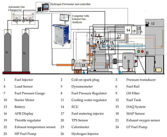
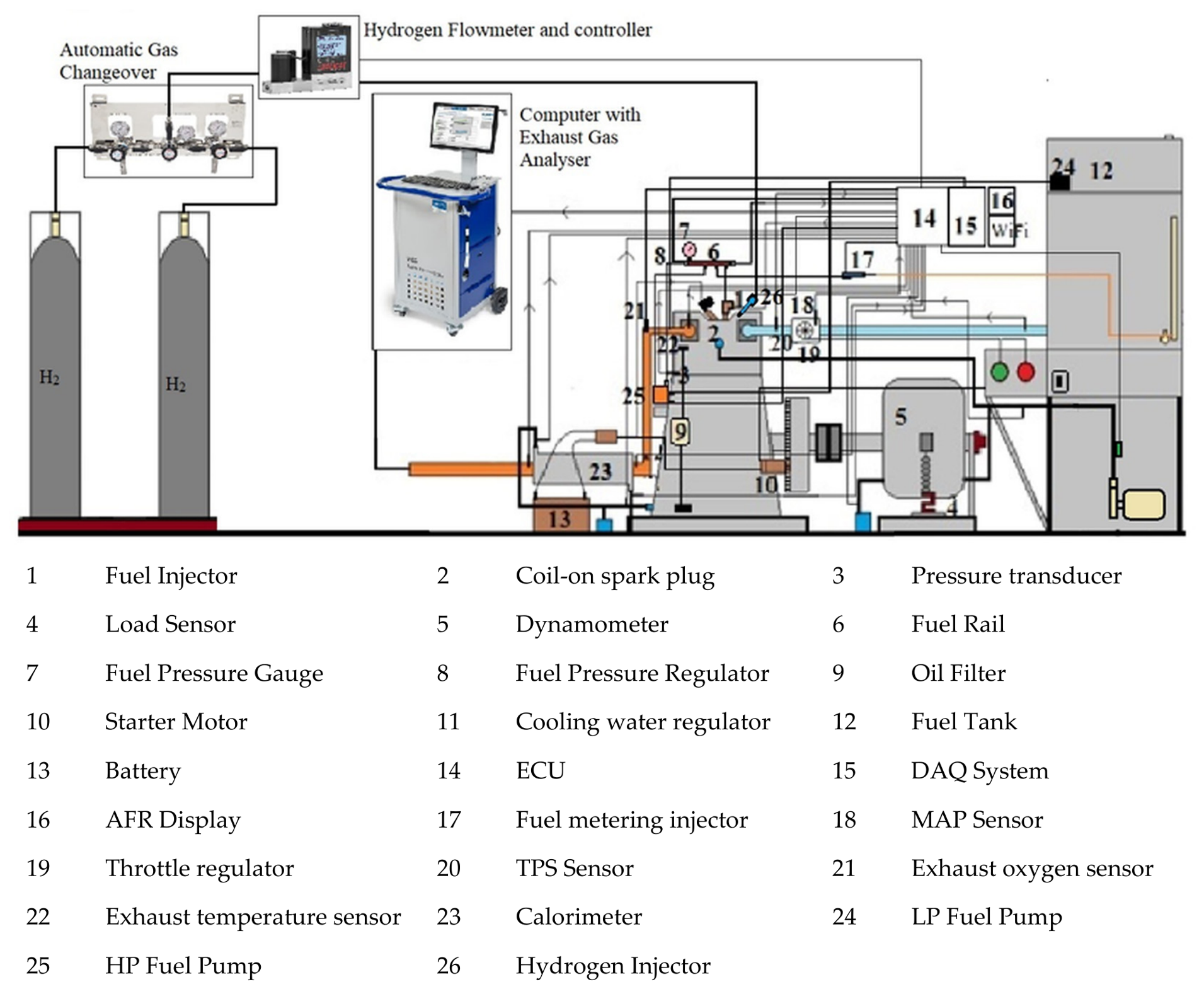
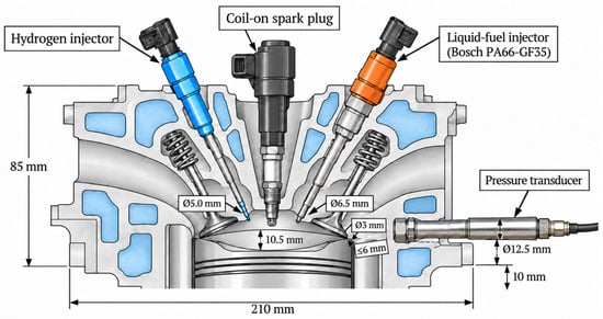
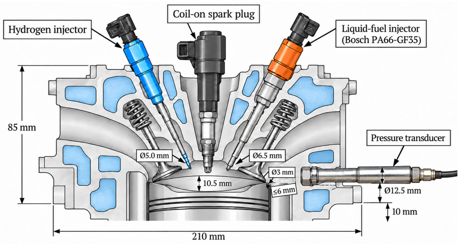
The experimental unit includes a 0.5-L single-cylinder DISI engine with a maximum torque of 32 Nm (at 2000 rpm) and a maximum power of 7.5 kW (at 2400 rpm) (specifications are listed in Table 1). The schematic is shown in Figure 1 and Figure 2. The cylinder head was slightly modified to house a low-pressure hydrogen DI injector (20 bar max) operating via a sequential injector control module integrated with the reprogrammable ECU (Performance Electronics PE3). The hydrogen injector is accompanied by the high-pressure wall-guided liquid-fuel direct injector (Bosch PA6635GF, Stuttgart, Germany) and an overhead coil-on-plug ignition-system-based spark unit (Bosch 0221604800). Both injectors are placed at the same angle on opposite sides of the spark plug. An electronically controlled high-pressure GDI pump (Bosch HDP5, Germany) received fuel from a low-pressure priming pump installed in the fuel tank and supplied it to these injectors via the fuel rail (Bosch PS-HPS4, Germany). Another injector of the same type, with the same injection timing, was used to measure the fuel injection rate at the entry to the 20 mL capacity burette, equipped with two level probes and a solenoid bypass valve, to measure the rate of fuel injection automatically. A fuel flowmeter was added to the fuel feed line, along with a logical transformation of it to metering in the software. The cooling jacket design was slightly modified, and a hole was drilled in the cylinder block for the water-cooled pressure sensor (Kistler 6056, Winterthur, Switzerland). A modified 54 mm throttle body (Bosch D261205358, Germany) was used in the airflow measurement system.
Table 1.
Engine Specification.
Figure 1.
Schematic of the test setup.
Figure 2.
Installations in the cylinder head with exact dimensions.
The intake system featured an electronically controlled throttle body and a throttle position sensor to provide adequate control of intake airflow. The throttle plate was operated by an electric motor with a wire linkage. Continuous measurement of intake manifold pressure was performed using a Bosch MAP sensor (0261230245, Germany). The air mass flow rate was measured with a Bosch MAF sensor (0280218232). The intake air temperature was measured in the intake manifold, 6 cm from the cylinder head bolt, using a temperature sensor. The tip of its sensing element was approximately 3 mm into the flow to obtain an accurate temperature reading. The exhaust system was also designed to be easier to instrument and maintain, featuring a removable exhaust manifold. A continuous recording EGT (exhaust gas temperature) measurement was taken at the manifold outlet using a Bosch EGT sensor (0986259013, Germany). During engine operation, the excess air ratio (λ) was monitored by a Bosch LSU 4.9 wideband lambda sensor, which is situated next to the EGT sensor and is directly connected to the engine control unit (ECU). The exhaust gas line was passed through a modified tube-in-tube exhaust gas calorimeter with four thermocouples to measure exhaust gas and cooling water inlet and outlet temperatures. The hydrogen supply line consists of two high-pressure cylinders containing 99.9% pure hydrogen at 320 bar each, connected to an automatic gas changeover (PCI Analytics 90262000, Thane, India), where the outlet pressure was maintained at 10 bar. This is further connected to a hydrogen mass flowmeter & controller (Alborg, XFM47S-VDL6-A2, Orangeburg, NY, USA), which is guided through the sequential injection system.
2.2. Exhaust Gas Monitoring
The exhaust gas emission values were measured using the AVL MDS250 analyser, which measures CO, CO2, O2, NOx, and unburnt hydrocarbons (HC). CO, CO2, and HC values were measured using the non-dispersive infrared sensor technique; the O2 value was measured using the paramagnetic sensor; and NOx was measured using an electrochemical detector cell. The temperature and airflow were maintained to ensure the air remained constant as it reached the measuring device. The emission values were processed and recorded using AVL DSS software Version 3.0 at a rate of 1 data point per second until reaching the steady state. The engine was started in its initial state before the experiment began. The emissions readings became stable, after which they were used to calculate certain values. The specific emission values in g/kW-h were calculated using the engine’s power and exhaust air flow rate via the following equation;
Here,
ei represents the specific emission of the entity, is the exhaust mass flow rate, Mi molecular mass of the entity, Mex molecular mass of exhaust, BP is the brake power in kW, and k is a constant with a value of 1 for entities measured in %, and 3 for entities measured in parts per million (ppm). The exhaust mass flow rate was obtained from data on air inflow and fuel supply. On the other hand, the molecular weight was calculated using data concerning the present air-fuel ratio.
2.3. Experimental Procedure
All the experiments were carried out at 2000 rpm, since the peak torque was observed at this speed under wide-open-throttle (WOT) conditions. The fuel injection pressure for ethanol was kept constant at 120 bar, while for hydrogen it was kept at 10 bar. The hydrogen injection timing was fixed at 26 °CA after TDC in the intake stroke, targeting the closed exhaust valve. However, the EIT was varied from 80 °CA after TDC to 160 °CA after TDC during the intake stroke in 10 °CA increments. The hydrogen quantity was varied from 0% to 20% by energy share, in 2.5% increments. The net energy input was kept constant across fuel variations, as in the baseline ethanol experiment. This means that the flow rate of both fuels is kept constant for any fuel composition across the varying EIT. The cooling water flow rate was kept constant at 150 L per hour, and after each experiment, the engine was returned to its initial condition. Each experiment was repeated twice, and the average of the three was considered for analysis. For each experiment, a total of 500 consecutive cycles were analysed after the engine attained operational stability at the specified engine speed. However, for the cyclic stability analysis, 200 consecutive cycles were considered for each experiment based on the maximum CoVIMEP.
2.4. Uncertainty Analysis
Measurement uncertainty was assessed for both the dependent and independent variables across all injection timings [57]. The engine tests were carried out at 2000 rpm under wide-open throttle, under varying environmental conditions in three different conditions. These environmental conditions were chosen to account for differences in ambient temperature and humidity, which may vary by area, whereas barometric pressure remained constant throughout the experiment. All experimental cases were run twice to improve the sample size. The observed uncertainty is listed in Table 2.
Table 2.
Measured Uncertainty.
3. Results and Discussion
The experimental data were processed to assess the effects of combining HES and EIT on the performance, combustion process, stability, and emission characteristics of the dual-direct-injection SI engine. The HES was changed from pure ethanol to 20% fuel, while the EIT was systematically varied from 80 °CA to 160 °CA ATDC in the intake stroke. The trend analysis will be performed on the values of BTE, ηvol, combustion period, cylinder pressure, HRR, CoVIMEP, and emission parameters. Special emphasis will be placed on the study of the relationship between ethanol mixture formation and hydrogen-assisted flame propagation, because changes in the HES value affect the quantities of both fuels injected into the cylinder.
3.1. Brake Thermal Efficiency (BTE) and Volumetric Efficiency (ηvol)
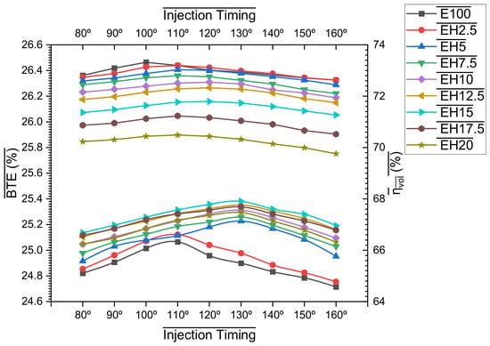
The different BTE values from Figure 3 (bottom) suggest a combined effect of EIT and HES. For E100, BTE increased from 24.821% at 80 °CA to a maximum of 25.065% at 110 °CA, then decreased to 24.715% at 160 °CA. Hydrogen supplementation resulted in a region of maximum efficiency that moved towards relatively retarded ethanol injection. At EH5 and EH7.5, the maximum BTEs were 25.227% and 25.258%, respectively, at 130 °CA, which further increased to 25.311%, 25.352%, and 25.381% for EH10, EH12.5, and EH15. Therefore, the highest BTE was achieved with EH15 at 130 °CA, an increase of approximately 1.94% over E100 at the same EIT. However, increasing HES beyond 15% reduced BTE to 25.338% for EH17.5 and 25.293% for EH20. This agrees with the idea that not all energy gains are continuously improved by hydrogen addition, but that there is an optimal energy substitution corresponding to the BTE improvement. The first BTE improvement is due to the high flame propagation rate, low ignition energy, and high diffusivity of hydrogen. These features promote faster combustion and produce more combustion heat at TDC, which means the combustion occurs closer to constant volume. The process of evaporation and mixture preparation changes when ethanol injection is retarded from the early intake stroke. With excessively early EIT, the time spent evaporating ethanol increases, but the cooling effect is more evenly distributed throughout the ethanol charge. The intermediate EIT ensures a good fuel mixture, effective local cooling via charge cooling, and good fuel stratification [58]. These benefits seem to be negated by shorter preparation time and greater compositional non-uniformity beyond 130 °CA.
Figure 3.
Influence of EIT and HES on BTE (bottom) and ηvol (top).
In contrast, the response of ηvol was the opposite of that of HES, as shown in Figure 3 (top). The maximum values obtained for E100, EH15 and EH20 were 73.321%, 71.796% and 70.489% at 100 °CA, respectively. The reduction in ηvol was about 3.58% at 130 °CA for EH15 and EH20, corresponding to 71.733% and 70.322%, respectively, compared to E100. An advantage of direct hydrogen injection over hydrogen port injection is that the significant air movement caused by port injection is avoided. Still, the more gas is injected, the more the in-cylinder charge conditions change. Moreover, the residual gas and wall temperatures increase due to faster hydrogen combustion, which may reduce the density of the inducted fresh charge. So, the best BTE at EH15 is achieved at a moderate volumetric-efficiency loss, suggesting that enhanced combustion and energy conversion outweigh the loss of cylinder fill.
3.2. Combustion Durations
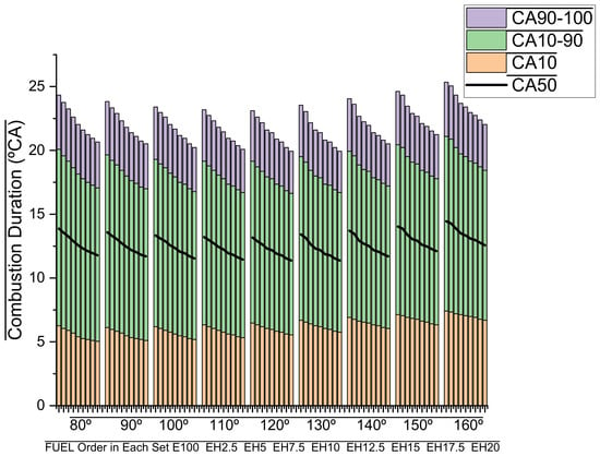
The combustion-duration characteristics in Figure 4 clearly demonstrate hydrogen’s ability to promote combustion. For E100, the flame-development period (CA10) varied from 6.264 °CA at 80 °CA EIT to 7.416 °CA at 160 °CA. The minimum value (6.120 °CA) was observed at 90 °CA, and CA10 increased gradually as ethanol injection was retarded. CA10 consistently increased as HES increased. At 130 °CA, CA10 decreased from 6.696 °CA for E100 to 6.408, 6.264, 6.192, 6.048, 5.976, 5.832, and 5.760 °CA for EH5-EH20, respectively. Thus, EH15 reduced flame development by nearly 10.8% and EH20 by around 14.0%, relative to E100. The same result was observed for the main combustion time (CA10-CA90). For E100, the shortest CA10-90 of 12.672 °CA was obtained when the injection was carried out at 120 °CA, while advancing or retarding the injection from this point led to a prolongation of the CA10-90 to 13.824 °CA and 13.680 °CA, respectively. This phase progressed gradually in the presence of hydrogen. The presence of hydrogen gradually accelerated this phase. At 130 °CA, CA10-90 decreased from 12.816 °CA for E100 to 12.024 °CA for EH5, 11.736 °CA for EH7.5, 11.664 °CA for EH10, 11.304 °CA for EH12.5 and EH15, 11.088 °CA for EH17.5, and finally 10.944 °CA for EH20. The latter is a 14.61% decrease compared with E100.
Figure 4.
Influence of EIT and HES on Combustion Duration.
The observed behaviour is mainly due to the significantly higher flame speed and diffusivity of hydrogen. The high concentration of H and OH radicals in the developing flame with hydrogen addition promotes faster growth of the flame kernel and subsequent oxidation of the ethanol-air mixture [59]. It also has a broad flammability limit, allowing the flame to spread through some locally lean areas that would not be readily burned by ethanol. EIT introduces a second controlling mechanism via ethanol evaporation and the spatial distribution of the ethanol/air mixture. Early injection provides sufficient evaporative time but may lead to less charge stratification [60]. However, too high a retardation also means there is less time between the atomization and evaporation of the ethanol and the ignition time, which accounts for the rise of CA10 to 160 °CA. The shortest period for the main combustion process is typically observed at an injection timing of 120–130 °CA; thus, this range can be considered a good compromise between mixture preparation and flame propagation. The progressive decrease in CA10 and CA10-90 by HES also accounts for the progressive development of the cylinder-pressure curve and the improvement in thermal efficiency up to the favourable range of hydrogen substitution.
3.3. Cylinder Pressure
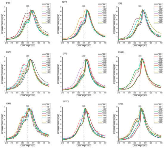
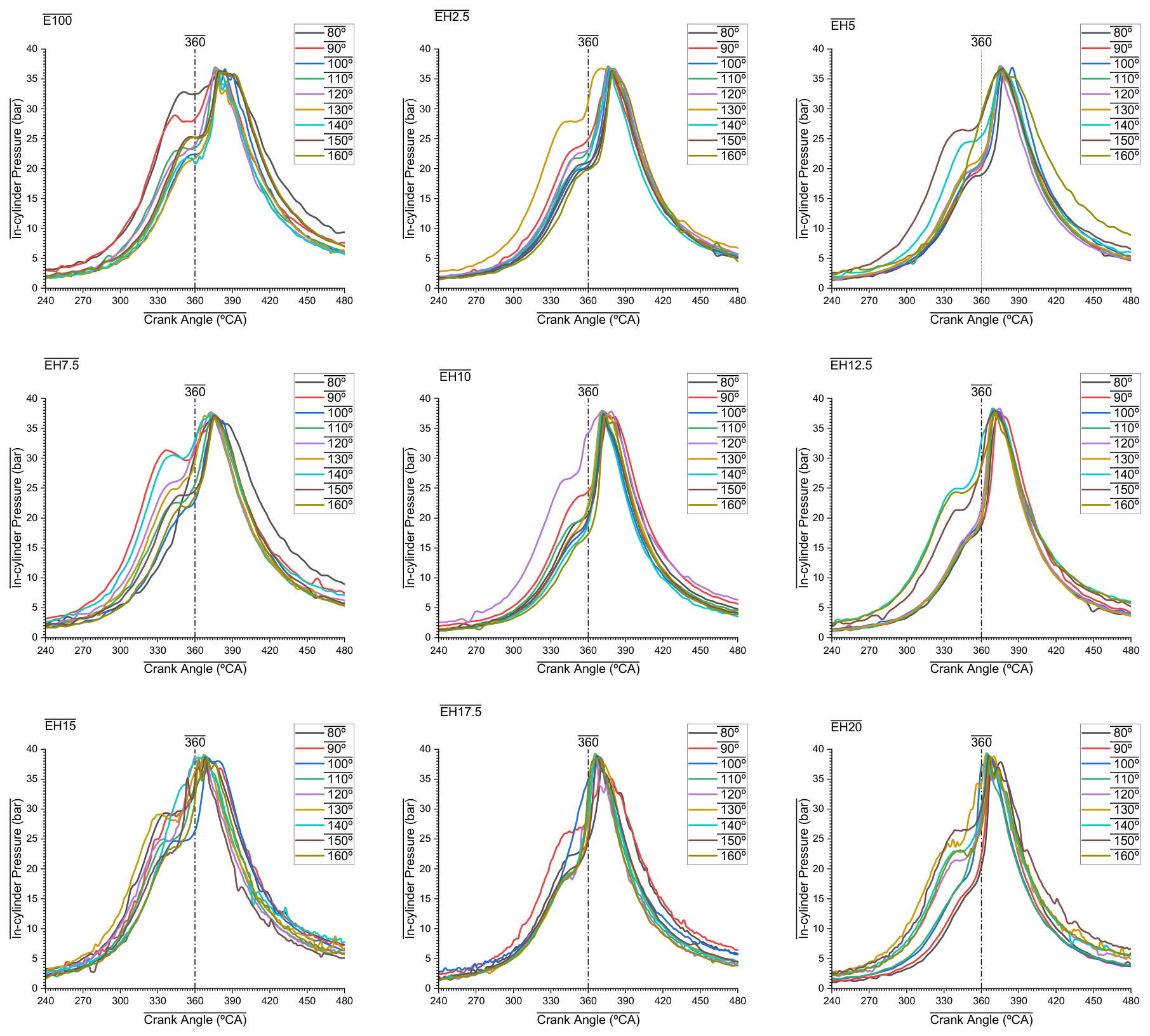
The cylinder-pressure characteristics were very sensitive to both EIT and HES, as shown in Figure 5. The Pmax for neat ethanol was relatively stable across the investigated EITs; however, as more hydrogen was added, Pmax increased, and the peak moved closer to TDC. The maximum cylinder pressure of E100 was 36.734 bar at around 377.57 °CA (17.57 °CA ATDC) at 130 °CA EIT. Increasing HES raised the Pmax to 36.854, 37.041, 37.582, 37.836, and 38.343 bar for EH2.5, EH5, EH7.5, EH10, and EH12.5, respectively. At higher hydrogen contributions, EH15, EH17.5, and EH20 measured 39.072, 39.296, and 39.366 bar, respectively. Thus, the cylinder Pmax was increased by roughly 6.36% for EH15 and 7.17% for EH20 compared to E100 at the same EIT. Most notably, the addition of hydrogen shifted the position of the maximum pressure. The pressure peak at 130 °CA EIT reduced from 17.57 °CA ATDC for E100 to 7.2 °CA ATDC for EH15 and 4.3 °CA ATDC for EH20. Therefore, shifting the point of maximum pressure by over 13 °CA for HES increased from 0% to 20%. This was also found at 120 °CA EIT. The Pmax for E100, EH15 and EH20 were 36.916 bar, 38.935 bar and 39.272 bar, respectively, representing improvements of about 5.47% and 6.38%, respectively. At the same time, it moved forward from about 16.7 °CA ATDC (E100) to 8.1 °CA (EH15) and 4.6 °CA ATDC (EH20). Thus, the numerical response suggests that the effect of hydrogen on combustion phasing is stronger than its effect on pressure magnitude.
Figure 5.
Influence of EIT and HES on Cylinder Pressure.
The rise in cylinder pressure is consistent with the observed decrease in flame development and main combustion duration. It has been found that hydrogen has a much higher laminar burning speed and diffusion rate than ethanol, and a lower minimum ignition energy requirement. This means that increasing the energy input will facilitate faster flame kernel formation and ultimately make it easier to propagate flames through the ethanol-air mixture. As a result, more of the fuel will burn near TDC when the instantaneous cylinder volume is smaller. EIT also influences ethanol atomization, evaporation, and spatial distribution before ignition. Excessively delayed ethanol injection decreases the preparation time of the fuel-air mixture [61]. In contrast, early injection enhances the evaporation time but alters the magnitude and distribution of ethanol-induced charge cooling. Therefore, the optimal EIT range enhances the interaction between ethanol mixture preparation and hydrogen-assisted flame propagation. It should be noted that, although cylinder pressure increased after EH15, the maximum value of BTE was recorded at EH15 at 130 °CA. The reason is that the maximum cylinder pressure does not always indicate maximum energy conversion. Advanced cylinder pressure development toward TDC results in additional negative compression work and increased heat losses due to prolonged contact between hot gas and the combustion chamber walls. Therefore, EH15 offers the most advantageous development of cylinder pressure; further increase in the amount of hydrogen leads to advanced combustion but does not improve thermal efficiency.
3.4. Heat Release Rate (HRR)
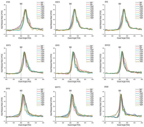
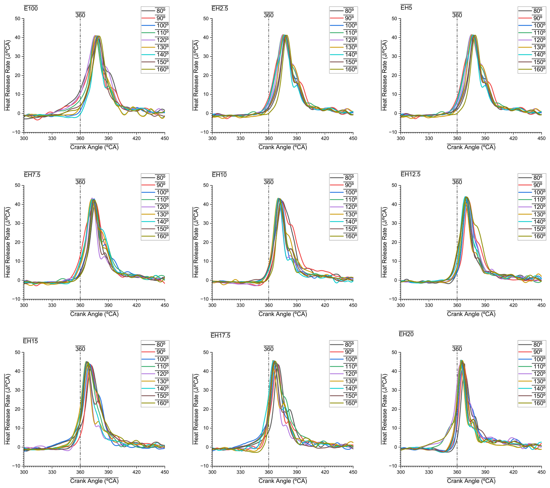
The HRR characteristics from Figure 6 also indicate the increased combustion intensity resulting from the addition of hydrogen. Both HRRmax and the crank angle at which it occurs changed significantly as HES increased. When the EIT was 120 °CA, E100 had an HRRmax of 41.032 J/°CA; raising the HES to EH2.5 and then to EH5 increased this figure to 41.505 and 41.795 J/°CA, respectively. A more substantial increase was then observed, with HRRmax values of 43.343 J/°CA for EH7.5, 43.224 J/°CA for EH10, 43.797 J/°CA for EH12.5, and 44.885 J/°CA for EH15. The highest hydrogen contents gave rise to HRRmax values of 45.361 J/°CA for EH17.5 and 45.605 J/°CA for EH20. As a result, EH15 increased HRRmax by about 9.39%, whereas EH20 increased it by 11.14% compared to E100 at the same injection timing. There was a significant forward shift of HRRmax as the level was increased. When the EIT was at 120 °CA, the maximum HRR for E100 occurred at about 375.84 °CA, or 15.84 °CA ATDC; for EH15, the corresponding maximum occurred at about 367.20 °CA, an advance of 8.64 °CA. EH17.5 advanced the peak to about 365.76 °CA, and EH20 achieved its maximum at about 363.46 °CA, that is, 3.46 °CA after TDC. Therefore, raising the HES from 0 to 20% caused the maximum energy-release rate to advance by approximately 12.38 °CA. The same kind of behaviour was observed at 110 °CA EIT, where HRRmax rose from 40.969 J/°CA for E100 to 44.511 J/°CA for EH15 and 45.118 J/°CA for EH20, corresponding to increases of about 8.65% and 10.13%, respectively. It is also evident from the data obtained that this variation in HRR clearly reflects the recorded combustion times. The time between CA10 and CA90 dropped from 12.672 °CA at E100 to 11.448 °CA at EH15 and 11.088 °CA at EH20. This means that there was a decrease in the combustion time for EH15 and EH20 by about 9.66% and 12.50%, respectively. From the increase in HRRmax and the decrease in combustion time, hydrogen increases the energy released over a shorter crank angle. The observed behaviour can mainly be traced to hydrogen’s high flame speed, diffusivity, and chemical reactivity. After the spark discharge, hydrogen causes the initial flame to develop rapidly and enhances the amount of reactive species in the reaction area. The flame that has formed then burns up the surrounding ethanol-air mixture at a faster rate. This leads to more concentrated combustion, increasing HRR and bringing the main energy-releasing process closer to TDC.
Figure 6.
Influence of EIT and HES on HRR.
The timing of ethanol injection affects this response by influencing the evaporation of the liquid fuel and the preparation of the mixture. If mixing is inadequate, there will be local areas that are either too rich or too cold, and these will burn more slowly. In contrast, appropriate injection timing ensures a suitable distribution before ignition. Hydrogen can help the combustion process in these locally unfavourable regions because of its wider flammability range, although it cannot eliminate the effects of mixture preparation. It is worth noting that from EH15 to EH20, HRRmax continued to increase, whereas BTE did not show the same trend. For instance, between EH15 and EH20, HRRmax rose from 44.885 to 45.605 J/°CA at 120 °CA, with combustion moving ever closer to TDC. Hence, it does not follow that an extremely rapid release of energy will always result in extra useful work; when combustion becomes too advanced, the extra compression work and the heat-transfer losses can cancel out the benefit of a faster burning rate. This is why the highest HRR is observed at the highest HES, even though the favourable thermal-efficiency area occurs at a relatively low hydrogen content.
3.5. Coefficient of Variation of IMEP (CoVIMEP)
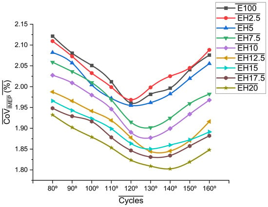
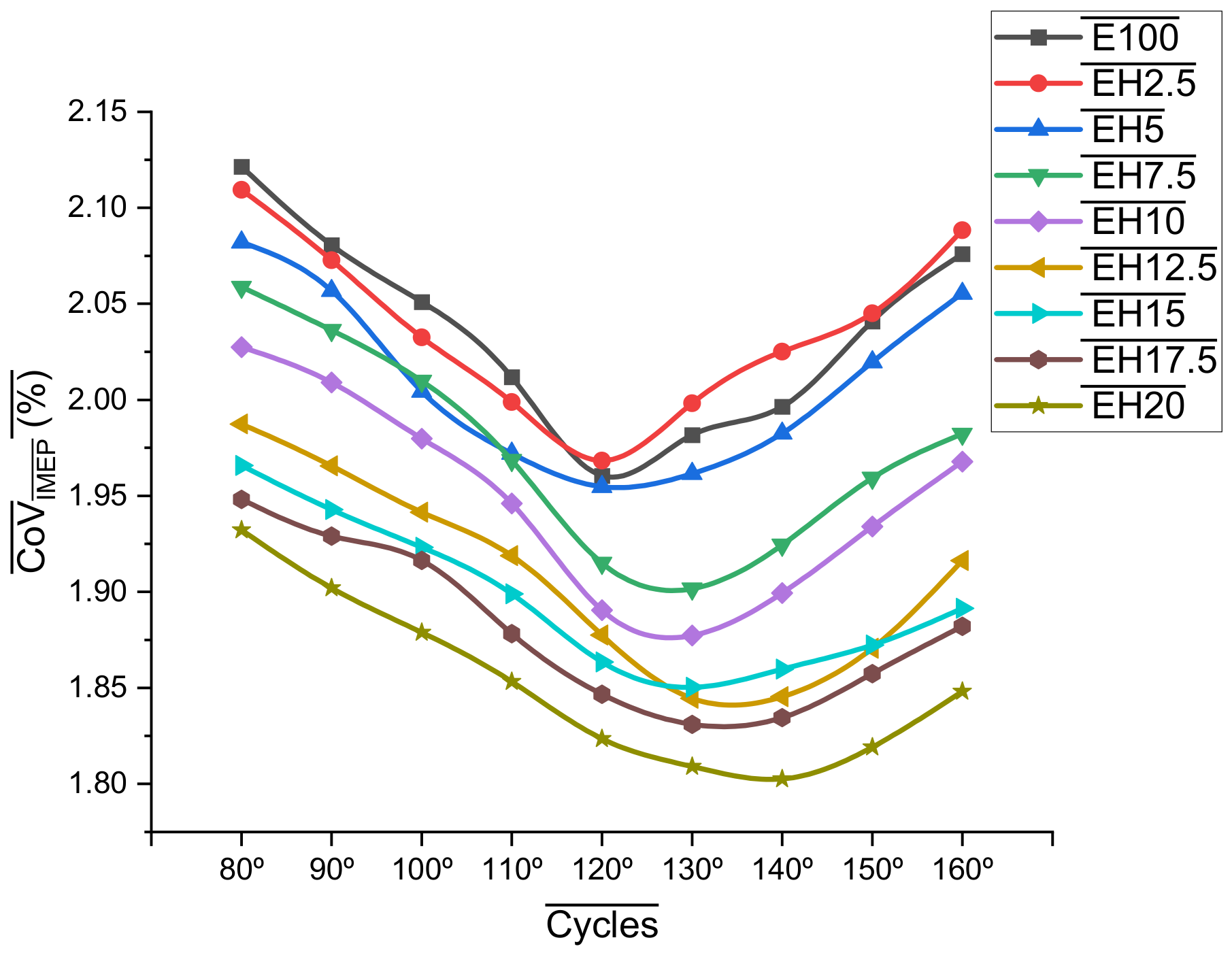
The CoVIMEP from Figure 7 indicates that combustion stability was influenced by both EIT and HES. For E100, CoVIMEP ranged from 1.9605% to 2.1215%. At 130 °CA EIT, EIT changed from 1.9817% for E100 to 1.9983% for EH2.5 and 1.9615% for EH5. At higher HES, CoVIMEP decreased to 1.8503% for EH15 and 1.8091% for EH20, corresponding to reductions of 6.63% and 8.71%, respectively, compared with E100. At 80 °CA, CoVIMEP decreased from 2.1215% for E100 to 1.9323% for EH20, representing an 8.92% reduction. At 150 °CA, it decreased from 2.0409% for E100 to 1.8723% for EH15 and 1.8191% for EH20, corresponding to reductions of 8.26% and 10.87%, respectively. This shows that increased chemical reactivity cannot fully make up for poor spatial mixing.
Figure 7.
Variations in CoVIMEP with EIT and HES.
The cycle-to-cycle variations observed in spark-ignition engines are due to fluctuations in the local equivalence ratio, turbulence level, residual-gas fraction, and the way the flame kernel develops around the spark plug. Since ethanol has an evaporative cooling effect and burns more slowly at the beginning, it is more sensitive to these fluctuations. The presence of hydrogen lowers sensitivity because the ignition energy is relatively low and the flammability range is wide, allowing ignition to occur across a broader range of local mixture parameters. A high flame velocity reduces flame development. However, with direct injection, spatial distribution becomes a factor. The injection of ethanol affects the evaporation process and charge distribution, whereas the injection of hydrogen produces a hydrogen concentration field within the engine cylinder. There may be an unfavourable influence of one on the other, thus creating cycle-related variations. The lower CoVIMEP in the area with higher HES and at intermediate EIT, therefore, corresponds to shorter CA10 and CA10-90 values, indicating that rapid and repeatable flame-kernel development is primarily responsible for the improved cyclic stability.
3.6. Peak Cylinder Temperature (Tmax) and Exhaust Gas Temperature (EGT)
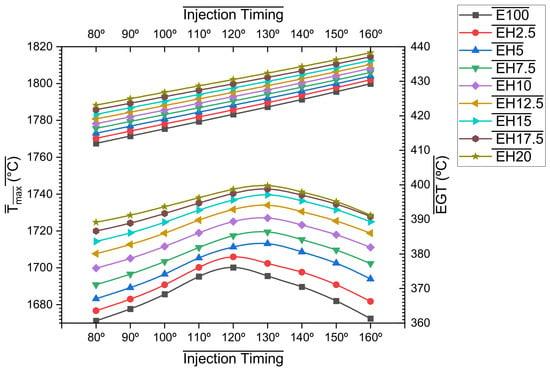
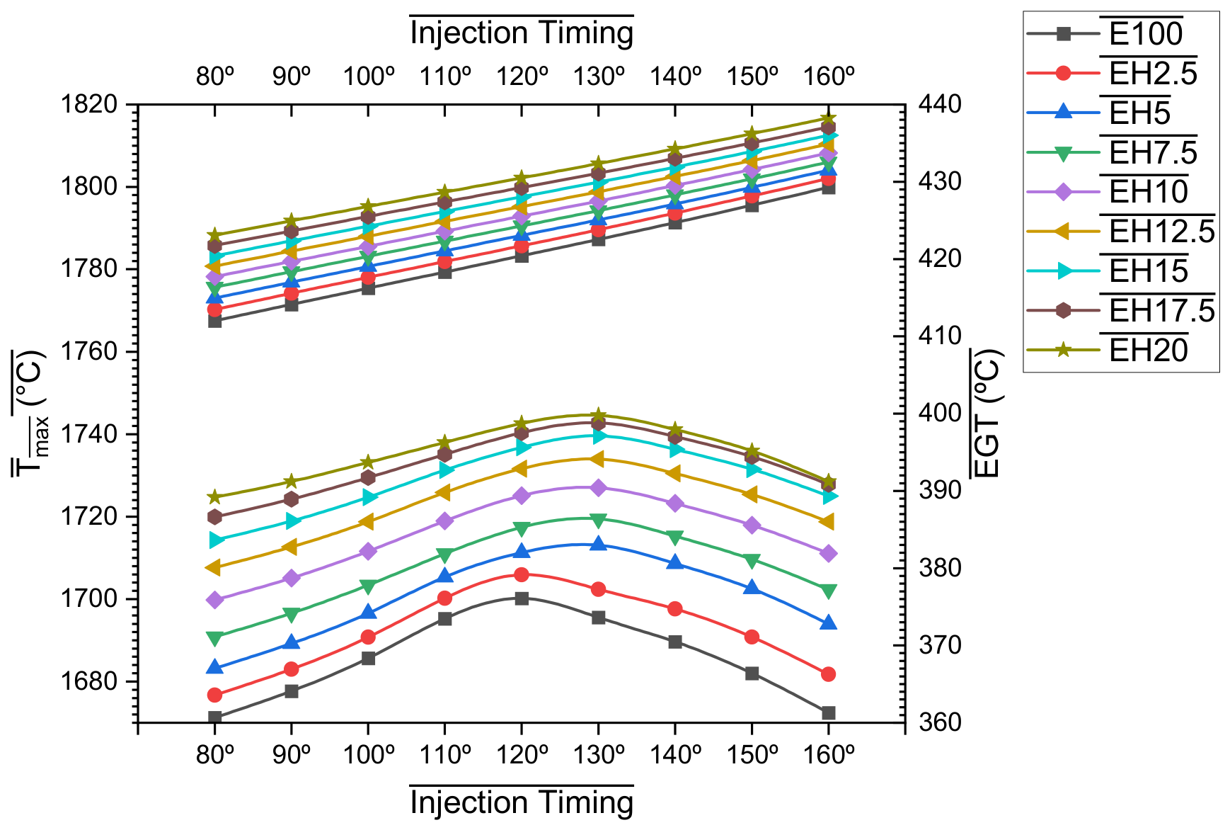
As shown in Figure 8, Tmax and EGT responded differently to EIT and HES. When EIT was retarded, Tmax first rose, reached a maximum between 120 °CA and 130 °CA, and then fell, while EGT increased continuously with EIT. With E100, Tmax rose from 1671.21 °C at 80 °CA to 1700.16 °C at 120 °CA, representing an increase of about 1.73%, before dropping to 1695.57 °C at 130 °CA and to 1672.44 °C at 160 °CA. Consequently, the temperature at 160 °CA became similar to that at the earliest injection point, indicating a clear intermediate EIT range favourable for intensified combustion. As HES increased, Tmax rose across all EITs. At 130 °CA, Tmax rose from 1695.57 °C for E100 to 1713.08 °C for EH5, to 1719.45 °C for EH7.5, to 1726.99 °C for EH10, and to 1733.97 °C for EH12.5; it then went on to 1739.62 °C for EH15, to 1742.73 °C for EH17.5, and to 1744.59 °C for EH20. Thus, compared with E100, EH15 and EH20 increased Tmax by approximately 2.60% and 2.89%, respectively. A comparable result was observed at 120 °CA, where Tmax increased from 1700.16 °C for E100 to 1736.82 °C for EH15 and 1742.62 °C for EH20, corresponding to increases of approximately 2.16% and 2.50%. Interestingly, the indicated ignition delay and the maximum combustion temperature changed with hydrogen addition. For the E100 blend, the maximum temperature was reached at 120 °CA, whereas for the EH5 blends, it was mostly reached at 130 °CA. When it comes to EH15, the maximum temperature was 1714.32 °C at 80 °CA, 1739.62 °C at 130 °CA, and it declined again to 1725.01 °C at 160 °CA. When it comes to EH20, the maximum temperature was 1724.72 °C at 80 °CA; it rose to 1744.59 °C at 130 °CA and then dropped to 1728.54 °C at 160 °CA. This pattern aligns well with the behaviour of BTE, cylinder pressure, and HRR, where the optimal combustion region shifted progressively to 120–130 °CA as hydrogen content increased.
Figure 8.
Influence of EIT and HES on Tmax (bottom), and EGT (top).
EGT showed a different behaviour. For E100, the EGT rose continuously from 412.00 °C at 80 °CA to 422.54 °C at 130 °CA and to 429.27 °C at 160 °CA, representing an overall increase of about 4.19%. The addition of hydrogen caused the EGT to rise over the entire EIT range. At 130 °CA, the EGT increased from 422.54 °C for E100 to 425.07 °C for EH5, 426.26 °C for EH7.5, 427.50 °C for EH10, 428.71 °C for EH12.5 and 429.95 °C for EH15; EH17.5 and EH20 raised it further to 431.11 °C and 432.34 °C respectively. At 160 °CA, the highest EGT of 438.26 °C was recorded for EH20, this being approximately 2.09% higher than the value for E100 at the same time. The response, in terms of Tmax, is linked to both hydrogen-induced combustion and the preparation of the ethanol mixture. Because hydrogen has a high flame propagation speed, combustion is accelerated, and more energy is generated near the top dead centre, which is consistent with the rise in both the maximum pressure and the heat release rate. Moderate retardation ensures adequate ethanol evaporation and proper distribution of the mixture. Still, excessive retardation shortens the preparation time and causes most of the combustion to occur during the expansion stroke. The main cause of the continuing rise in EGT when ethanol injection is retarded is that, since the ethanol injection is delayed past the favourable mixture-preparation area, combustion becomes increasingly delayed, and a larger part of the energy release occurs during the expansion stroke. As a result, less thermal energy is converted into useful expansion work, and more remains in the exhaust gases. The increase in HES partly contributes to this rise in temperature because the faster hydrogen-assisted oxidation raises the overall combustion temperature. Thus, Tmax corresponds to the region of strongest in-cylinder combustion around 120–130 °CA. At the same time, the increasing EGT at late EIT indicates a gradual increase in the rejection of exhaust energy, which is why retarding ethanol injection beyond the optimal region does not affect BTE, even though the exhaust temperature continues to rise.
3.7. CO and HC Emissions
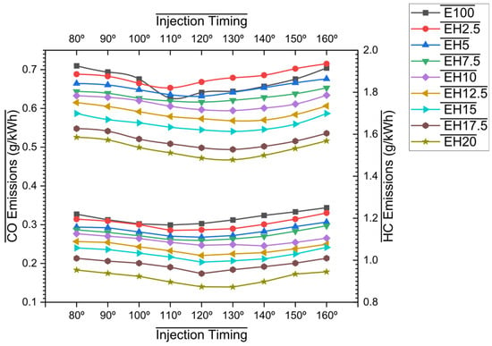
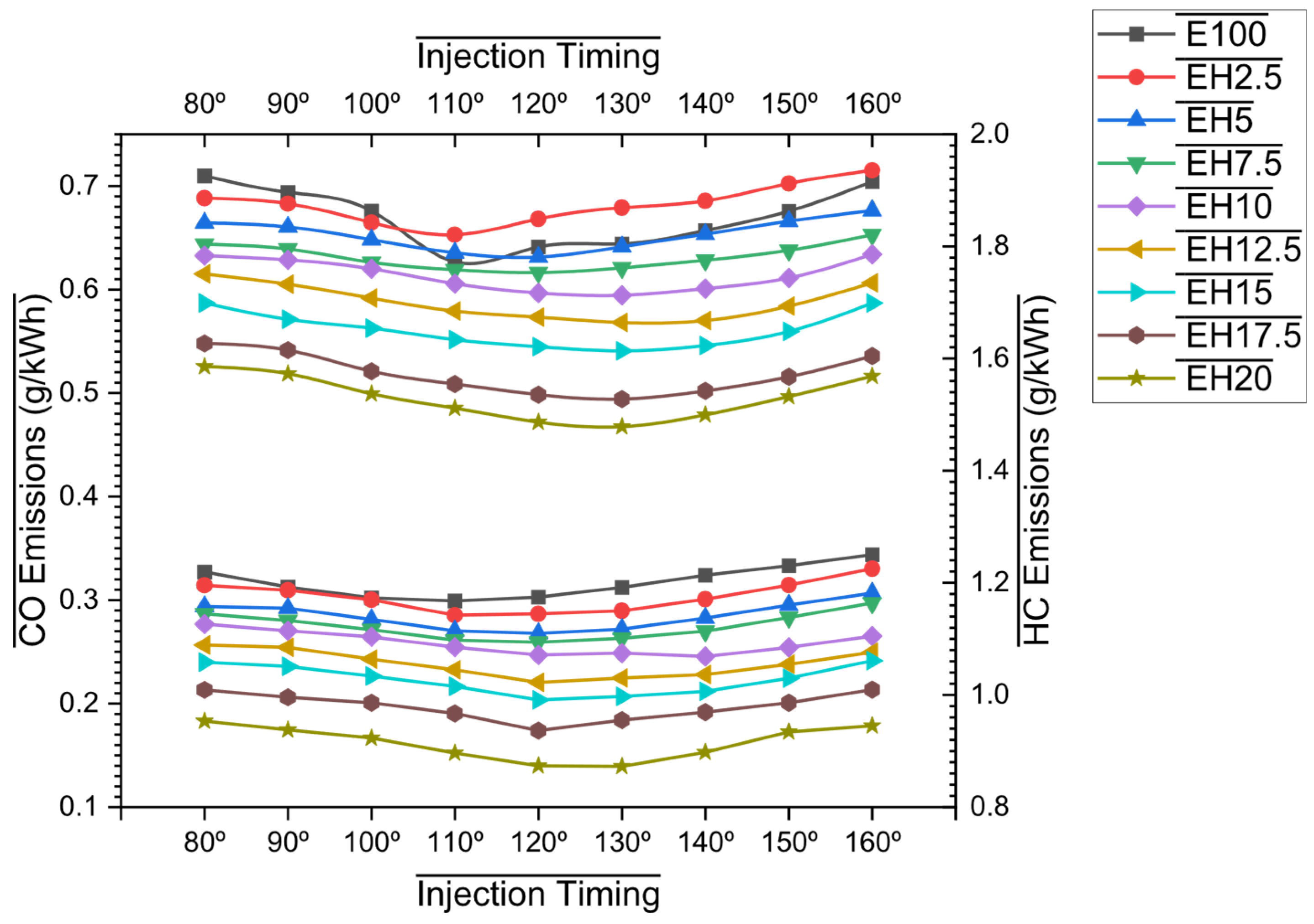
The emissions of carbon monoxide and hydrocarbons showed a strong dependence on both EIT and HES, with pressure generally reducing emissions of both by-products. From Figure 9 (bottom), at E100, CO first decreased as the injection timing was retarded, falling from 0.710 g/kWh at 80 °CA to 0.627 g/kWh at 110 °CA, which corresponds to a decrease of about 11.69%; further retardation of the injection timing then caused an increase in CO, it rising to 0.644 g/kWh at 130 °CA and then to 0.704 g/kWh at 160 °CA. Hence, the response of E100 shows that an intermediate injection timing leads to better ethanol evaporation and mixture preparation, while extremely early or late injection results in a relatively higher degree of incomplete oxidation. The addition of hydrogen made a significant difference to this behaviour. At 130 °CA, the amount of CO fell from 0.644 g/kWh with E100 to 0.641, 0.621, 0.594, 0.568, and 0.541 g/kWh with EH5, EH7.5, EH10, EH12.5, and EH15, respectively. EH10, EH12.5, and EH15 thus reduced CO by about 7.76%, 11.80%, and 16.05%, respectively. When the amount of HES was further increased, CO decreased to 0.467 g/kWh with EH20, representing a large reduction of 27.42% compared with E100 at the same EIT. Unlike BTE, which reached its beneficial range around EH15, CO continued to decrease at higher HES, indicating that oxidation still occurs even as the thermal-efficiency advantage begins to fade.
Figure 9.
Influence of EIT and HES on CO Emissions (bottom) and HC Emissions (top).
HC from Figure 9 (top) showed a similar response. When the temperature reached 130 °CA, E100 yielded 1.192 g/kWh, this figure dropping to 1.117 g/kWh for EH5, 1.101 g/kWh for EH7.5, 1.075 g/kWh for EH10, 1.030 g/kWh for EH12.5, and 0.997 g/kWh for EH15; these represented reductions of about 6.29%, 7.63%, 9.82%, 13.59% and 16.36% respectively. At EH20, HC fell further to 0.873 g/kWh, which was about 26.76% lower than E100. For neat ethanol, the lowest HC value was about 1.168 g/kWh at 110 °CA, while the favourable range shifted towards 120–130 °CA as the hydrogen content increased. The extent to which carbon monoxide and hydrocarbons decrease and then increase because of ethanol injection is mainly due to the way the ethanol mixture is prepared. With injection occurring very early, there is enough time for evaporation; yet the high latent heat of vaporisation of ethanol causes a significant cooling of the charge. On the other hand, if injection is delayed too long, the time available for droplet evaporation and for fuel and air to become well mixed is reduced, which in turn increases the likelihood of locally rich areas and incomplete oxidation. Thus, an intermediate EIT value strikes a better balance among evaporation, cooling, and the mixture’s spatial distribution. Hydrogen has an additional effect: it is chemically reactive and readily combustible. Because of its high flame speed and wide flammability range, it accelerates combustion in locally lean or diluted areas where ethanol’s flame propagation might otherwise be weaker. This finding is consistent with the measured decreases in CA10 and CA10-90, as well as the observed increase in HRR. The quicker combustion also enables the primary oxidation reaction to be finished earlier during the expansion stroke. Moreover, as HES increases, the amount of carbon-containing ethanol required to deliver the same amount of fuel energy decreases. The combined result of less available carbon and better oxidation is therefore to reduce both HC and CO. Yet the fact that emissions of CO and HC continue to decrease beyond EH15, even though the BTE has dropped, shows that the condition of minimum incomplete-combustion emissions and maximum thermal efficiency does not have to occur at the same fuel-energy distribution.
3.8. CO2 and NOx Emissions
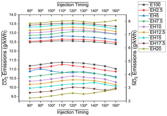
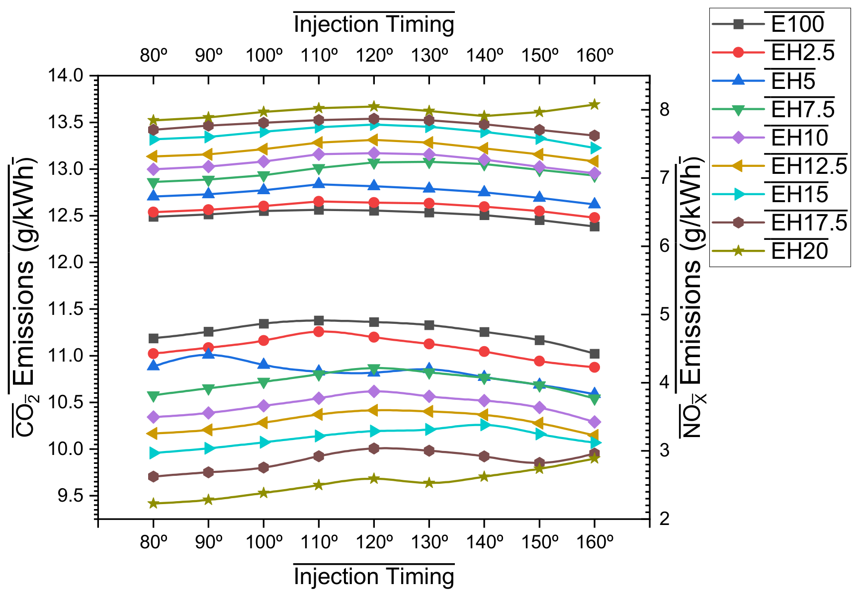
The behaviour of the CO2 and NOx values was entirely the opposite when hydrogen was added. From Figure 10 (top), as HES increased, CO2 decreased because hydrogen replaced part of the carbon-containing ethanol. In contrast, NOx increased because faster combustion, aided by hydrogen, led to higher combustion intensity and temperature. For an engine ignition delay (EIT) of 130 °CA, the CO2 amount was 11.330 g/kWh for E100. For EH5, EH7.5, EH10, and EH12.5, the amount of CO2 was found to be 10.854 g/kWh, 10.823 g/kWh, 10.565 g/kWh, and 10.404 g/kWh, respectively. Thus, the percentage reductions in CO2 emissions were 4.20%, 4.47%, 6.75%, and 8.17%, respectively, relative to E100. Nevertheless, CO2 emissions decreased again as the share of hydrogen increased. At EH15, CO2 emissions were 10.210 g/kWh, which is 9.89% lower than at E100; on the other hand, at EH20, the reduction was 9.637 g/kWh of CO2, representing 14.94% at 130 °CA. The reaction to EIT was rather different in the case of pure ethanol. CO2 rose from about 11.188 g/kWh at 80 °CA to 11.378 g/kWh at 110 °CA, then fell to approximately 11.330 g/kWh at 130 °CA and to 11.023 g/kWh at 160 °CA. The higher CO2 level in the range where ethanol injection is most favourable is accompanied by lower CO and HC levels, indicating that the available carbon is more completely converted to CO2. The way in which CO2 is interpreted is therefore different from that in the case of CO and HC. While a higher CO2 concentration at a constant ethanol amount may indicate better oxidation, an increase in HES reduces the carbon available for CO2 formation. The present study, by varying the energy contribution rather than simply the fuel volume, shows that increasing HES also reduces the amount of ethanol required to meet the energy requirement. It follows that the considerable decrease in CO2 observed at higher HES is mainly due to substitution of carbon by hydrogen rather than to a deterioration in the completeness of combustion. This conclusion is further supported by the simultaneous decrease in both CO and HC.
Figure 10.
Influence of EIT and HES on CO2 Emissions (top), and NOx Emissions (bottom).
NOx exhibited a contrary behaviour to that of CO2 as observed from Figure 10 (bottom). For 130 °CA, it rose from 6.496 g/kWh for E100 to 6.843 g/kWh for EH5, then to 7.239 g/kWh for EH7.5. That means an increase of approximately 5.34% and 11.44%, respectively. NOx then jumped to 7.346 g/kWh for EH10, 7.519 g/kWh for EH12.5 and 7.751 g/kWh for EH15. In that case, there were increases of about 13.09%, 15.75%, and 19.32%, respectively, compared to neat ethanol. The combustion results strongly support the rise in NOx. When the EIT is comparable, an increase in HES leads to higher Pmax and HRR, along with a substantial advance in the timing of these peaks towards TDC. For instance, at 130 °CA, Pmax rose from 36.734 bar with E100 to 39.072 bar with EH15 and to 39.366 bar with EH20. Similarly, the combustion-duration analysis showed that both CA10 and CA10-90 became progressively shorter as the hydrogen content increased. This shows that the energy release became faster and more concentrated, thus raising the local burned-gas temperature. Thermal NOx production is particularly sensitive to the duration at high temperature, oxygen concentration, and combustion temperature [62]. The reason for this effect is the latent heat of vaporisation of ethanol, which lowers the charge temperature as the fuel evaporates. Nevertheless, as the amount of hydrogen increases, the combustion-promoting effect of hydrogen begins to overcome the cooling effect of ethanol. In that case, hydrogen replacement would create a trade-off in emissions: while substituting carbon reduces CO2 emissions and enhances CO and hydrocarbon oxidation, NOx will increase [63].
4. Conclusions
An experimental investigation was conducted to examine the combined effect of ethanol injection timing (EIT) and the share of hydrogen energy (HES) in a DISI engine with parallel direct injections of ethanol and hydrogen. The EIT varied from 80 °CA to 160 °CA ATDC, and the HES varied from 0 to 20%, with the hydrogen injection pressure kept constant. The results were analysed and briefly discussed, with theoretical possibilities considered. The key outcomes of the present investigation are as follows.
- The combined optimisation of EIT and HES found that EH15 at 130 °CA was the highest-BTE condition, achieving a maximum BTE of 25.381%, about 1.94% higher than that obtained with E100 at the same EIT. Even though combustion was intensified, increasing HES above 15% decreased BTE, indicating an optimal level of hydrogen energy substitution for efficiency.
- Hydrogen greatly sped up both phases of combustion; at 130 °CA EIT, EH15 reduced CA10 and CA10-90 by about 10.8% and 11.8%, respectively, and EH20 caused reductions of 14.0% and 14.61%. The fact that a favourable combustion duration range occurs around 120–130 °CA indicates that hydrogen-assisted flame propagation depends strongly on how the ethanol mixture is prepared, as has been observed through injection phasing.
- Combustion intensity increased with increasing HES volume, and combustion was pushed closer to TDC. For example, at 130 °CA, Pmax increased from 36.734 bar for E100 to 39.072 bar for EH15 and then to 39.366 bar for EH20, and the timing of its occurrence changed from 17.57 °C after top dead centre for E100 to 7.2 °C after top dead centre for EH15 and then to 4.3 °C after top dead centre for EH20.
- Hydrogen enhanced the repeatability of combustion while increasing thermal intensity. Compared with E100, CoVIMEP fell by approximately 6.63% for EH15 and 8.71% for EH20, while Tmax rose by 2.60% and 2.89%, respectively. On the other hand, as the EIT was retarded, the EGT increased continuously, indicating that when ethanol injection was carried out too late, a larger share of the available thermal energy was transferred to the exhaust.
- The use of hydrogen resulted in considerable reductions in carbonaceous emissions but increased NOx levels. When the engine was at 130 °CA, EH15 reduced CO, HC, and CO2 by about 16.05%, 16.36%, and 9.89%, respectively, while NOx increased by 19.32%. At EH20, the reductions in CO, HC, and CO2 were even larger, indicating that the point at which carbonaceous emissions are at a minimum and the point at which BTE is at a maximum correspond to different hydrogen energy shares.
5. Limitations
In the present case, no hydrogen detector was available on the AVL MDS250 equipment used in this study; therefore, the molecular hydrogen concentration in the exhaust was not measured. The emissions recorded from the test engine consist of carbon-containing unburned hydrocarbons, excluding H2. Direct injection of hydrogen into the cylinder occurred at 26 °CA ATDC during the intake stroke, rather than being delivered via the intake manifold, to minimise the risk of hydrogen loss from intake flow reversals. However, hydrogen may go unburned for other reasons.
Author Contributions
J.K.P.: Conceptualization, Methodology, Experimentation, Original Draft. J.R.: Validation, Review, Supervision. S.B.B.: Methodology, Data Collection, Formal Analysis. N.K.: Resources, Review and Editing. All authors have read and agreed to the published version of the manuscript.
Funding
This research received no external funding.
Data Availability Statement
The raw data supporting the conclusions of this article will be made available by the authors on request.
Acknowledgments
During the preparation of this manuscript/study, the author(s) used Grammarly for the purposes of language editing. The authors have reviewed and edited the output and take full responsibility for the content of this publication.
Conflicts of Interest
The authors declare no conflicts of interest.
Abbreviations
The following abbreviations are used in this manuscript:
| ATDC | After Top Dead Centre |
| BSFC | Brake Specific Fuel Consumption |
| BTE | Brake Thermal Efficiency |
| CA10 | Flame Development Period |
| CA10-90 | Flame Propagation Period |
| CA50 | Combustion Duration Corresponding to 50% Mass of fuel Burnt |
| CA90-100 | After Burning Period |
| CoVIMEP | Coefficient of Variations in IMEP |
| DAQ | Data Acquisition |
| DI | Direct Injection |
| DISI | Direct Injection Spark Ignition |
| E100 | Ethanol |
| ECU | Engine Control Unit |
| EGT | Exhaust Gas Temperature |
| EIT | Ethanol Injection Timing |
| EHx | Ethanol Hydrogen Blend (x% of Hydrogen) |
| GDI | Gasoline Direct Injection |
| HC | Hydrocarbon |
| HDI | Hydrogen Direct Injection |
| HES | hydrogen energy share |
| HRR | Heat Release Rate |
| HRRmax | Peak Heat Release Rate |
| IMEP | Indicated Mean Effective Pressure |
| MAP | Manifold Absolute Pressure |
| NOx | Oxides of Nitrogen |
| Pmax | Peak Cylinder Pressure |
| SI | Spark Ignition |
| TDC | Top Dead Centre |
| Tmax | Peak Cylinder Temperature |
| WOT | Wide Open Throttle |
| ηvol | Volumetric Efficiency |
References
- Erdiwansyah; Mamat, R.; Ghazali, M.F.; Basrawi, F.; Rosdi, S.M.; Bahagia. A recent review of alternative fuels in SI engines: Performance, emissions, and combustion aspects. Next Res. 2025, 2, 100810. [Google Scholar] [CrossRef] [Scilit]
- Gautam, A.; Misra, R.N.; Agarwal, A.K. Biodiesel as an alternate fuel for diesel traction on Indian Railways. In Locomotives and Rail Road Transportation: Technology, Challenges and Prospects; Springer: Singapore, 2017; pp. 73–112. [Google Scholar] [CrossRef] [Scilit]
- Kolmeijer, H.; Nabera, A.; Martín, A.J.; Guillén-Gosálbez, G.; Pérez-Ramírez, J. A feasible methanol economy for a green future. Green Chem. 2026, 28, 174–185. [Google Scholar] [CrossRef] [Scilit]
- Wu, K.; Lu, Q.; Cao, Q.; Dhmees, A.S.; Yang, K.; Wang, S.; Yu, J.; Hu, L.; Zhang, H. Hydrolytic and pyrolytic technologies of pretreatment lignocellulose for production of ethanol fuels—A comparative review. Ind. Crops Prod. 2024, 218, 118840. [Google Scholar] [CrossRef] [Scilit]
- Kumar, G.; Padhy, R.; Das, D.; Narayana, S.A. Ethanol Fuel Blending Program in India: Analysis of Environmental, Economic, and Policy Aspects Using System Dynamics Approach. J. Adv. Transp. 2024, 2024, 2002187. [Google Scholar] [CrossRef] [Scilit]
- Lin, J.; Gaustad, G.; Trabold, T.A. Profit and policy implications of producing biodiesel-ethanol-diesel fuel blends to specification. Appl. Energy 2013, 104, 936–944. [Google Scholar] [CrossRef] [Scilit]
- Zhang, Z.; Zhang, L.; Wu, S. Does ethanol-blended gasoline policy improve air quality in China? Energy Econ. 2024, 134, 107579. [Google Scholar] [CrossRef] [Scilit]
- Valera, H.; Agarwal, A.K. India’s growing Ethanol Blending Program and implications of scalable and sustainable Methanol Blending Program for transport sector. Transp. Policy 2025, 165, 179–193. [Google Scholar] [CrossRef] [Scilit]
- Iodice, P.; Cardone, M. Ethanol/gasoline blends as alternative fuel in last generation spark-ignition engines: A review on co and hc engine out emissions. Energies 2021, 14, 4034. [Google Scholar] [CrossRef] [Scilit]
- Khedr, A.M.; Ismael, M.A.; El-Adawy, M.; Elserfy, K.; Abdelhafez, A.; Habib, M.A.; Nemitallah, M.A. Effects of Ethanol-Gasoline Blending on Combustion, Performance, and Emissions of a Spark Ignition Engine: An Experimental and Detailed Chemistry-Based Numerical Study. ACS Omega 2026, 11, 22017–22030. [Google Scholar] [CrossRef] [Scilit] [PubMed]
- Calvin, Y.L.; Hariyanto, P.A.T.; Usman, A.I.; Masuku, M.; Wibowo, C.S.; Maymuchar; Anggarani, R.; Fathurrahman, N.A.; Sugiarto, B. Volatility and physicochemical properties of gasoline-ethanol blends with gasoline RON-based 88, 90, and 92. Fuel 2022, 307, 121850. [Google Scholar] [CrossRef] [Scilit]
- Wang, X.; Gao, J.; Chen, Z.; Chen, H.; Zhao, Y.; Huang, Y.; Chen, Z. Evaluation of hydrous ethanol as a fuel for internal combustion engines: A review. Renew. Energy 2022, 194, 504–525. [Google Scholar] [CrossRef] [Scilit]
- Kumar, T.S.; Ashok, B.; Saravanan, B. Calibration of flex-fuel operating parameters using grey relational analysis to enhance the output characteristics of ethanol powered direct injection SI engine. Energy 2023, 281, 128340. [Google Scholar] [CrossRef] [Scilit]
- Kim, T.; Moon, J.; Jeon, J. Characterization of in-cylinder spatiotemporal flame and solid particle emissions for ethanol-gasoline blended in gasoline direct injection engines. Energy 2023, 283, 128492. [Google Scholar] [CrossRef] [Scilit]
- Li, X.; Li, D.; Liu, J.; Ajmal, T.; Aitouche, A.; Mobasheri, R.; Rybdylova, O.; Pei, Y.; Peng, Z. Exploring the potential benefits of Ethanol Direct Injection (EDI) timing and pressure on particulate emission characteristics in a Dual-Fuel Spark Ignition (DFSI) engine. J. Clean. Prod. 2022, 357, 131938. [Google Scholar] [CrossRef] [Scilit]
- Zhao, Z.; Li, M.; Liu, Y.; Yu, X.; Sang, T.; Sun, P.; Shang, Z.; Li, Z. Comparative study on combustion and emission of ternary-fuel combined supply SI engine with oxyhydrogen/ethanol/gasoline by different injection modes of fuel. Case Stud. Therm. Eng. 2024, 61, 105015. [Google Scholar] [CrossRef] [Scilit]
- Kumar, T.S.; Ashok, B.; Saravanan, B.; Tamilvanan, A.; Szpica, D. Development of optimal engine control map for flex fuel application in ethanol powered direct injection spark ignition engine. Fuel 2025, 384, 133934. [Google Scholar] [CrossRef] [Scilit]
- Voris, A.R.; Lundberg, M.; Puzinauskas, P.V. Effect of ethanol content, water injection, and compression ratio on combustion and detailed emissions in an SI-GDI engine. Fuel 2025, 381, 133200. [Google Scholar] [CrossRef] [Scilit]
- Hong, B.; Lius, A.; Mahendar, S.K.; Mihaescu, M.; Cronhjort, A. Energy and exergy characteristics of an ethanol-fueled heavy-duty SI engine at high-load operation using lean-burn combustion. Appl. Therm. Eng. 2023, 224, 120063. [Google Scholar] [CrossRef] [Scilit]
- Isobe, K.; Yoshimura, K.; Kobayashi, T.; Sok, R.; Kusaka, J. Impacts of low-temperature heat release on unstretched laminar burning velocity in advanced flex-fuel gasoline-ethanol engines. Appl. Therm. Eng. 2025, 258, 124826. [Google Scholar] [CrossRef] [Scilit]
- Nour, M.; Zhang, W.; Cui, M.; Fu, J.; Luo, X.; Qiu, S.; Li, X.; Xu, M. Comprehensive experimental analysis on combustion characteristics of acetone-butanol-ethanol fuel in a constant volume combustion chamber under gasoline direct injection conditions: Effect of fuel composition. Energy Convers. Manag. 2025, 339, 119948. [Google Scholar] [CrossRef] [Scilit]
- Perrone, D.; Falbo, B.; Castiglione, T. Experimental set-up and numerical optimization of a heavy-duty single-point SI engine fueled with ethanol for a generator set. Fuel 2026, 423, 139249. [Google Scholar] [CrossRef] [Scilit]
- Pandey, J.K.; Varghese, G.; Santhosh, K.; Kumari, A. Studying the behavior of ethanol-diethyl ether-based flex fuels in a direct injection SI engine. Energy 2025, 336, 138390. [Google Scholar] [CrossRef] [Scilit]
- Iodice, P.; Senatore, A.; Langella, G.; Amoresano, A. Effect of ethanol–gasoline blends on CO and HC emissions in last generation SI engines within the cold-start transient: An experimental investigation. Appl. Energy 2016, 179, 182–190. [Google Scholar] [CrossRef] [Scilit]
- Mohammed, M.K.; Balla, H.H.; Al-Dulaimi, Z.M.H.; Kareem, Z.S.; Al-Zuhairy, M.S. Effect of ethanol-gasoline blends on SI engine performance and emissions. Case Stud. Therm. Eng. 2021, 25, 100891. [Google Scholar] [CrossRef] [Scilit]
- Kumbhar, S.; Khot, S.; Bhapkar, U.; Patil, V.; Singh, P.; Husainy, A. Energy-exergy and exergoeconomic analysis of a hydrogen-enriched spark-ignition engine fueled with premium gasoline-ethanol blends. Int. J. Hydrogen Energy 2025, 137, 689–709. [Google Scholar] [CrossRef] [Scilit]
- Tian, Z.; Wang, Y.; Zhen, X.; Liu, D. Numerical comparative analysis on performance and emission characteristics of methanol/hydrogen, ethanol/hydrogen and butanol/hydrogen blends fuels under lean burn conditions in SI engine. Fuel 2022, 313, 123012. [Google Scholar] [CrossRef] [Scilit]
- Suresh, D.; Porpatham, E. Influence of high compression ratio on the performance of ethanol-gasoline fuelled lean burn spark ignition engine at part throttle condition. Case Stud. Therm. Eng. 2024, 53, 103832. [Google Scholar] [CrossRef] [Scilit]
- Zhen, X.; Li, X.; Wang, Y.; Liu, D.; Tian, Z. Comparative study on combustion and emission characteristics of methanol/hydrogen, ethanol/hydrogen and methane/hydrogen blends in high compression ratio SI engine. Fuel 2020, 267, 117193. [Google Scholar] [CrossRef] [Scilit]
- Ayad, S.M.M.E.; Belchior, C.R.P.; Sodré, J.R. Hydrogen addition to ethanol-fuelled engine in lean operation to improve fuel conversion efficiency and emissions. Int. J. Hydrogen Energy 2024, 49, 744–752. [Google Scholar] [CrossRef] [Scilit]
- Amaral, L.V.; Malaquias, A.C.T.; Fraga, M.A.; Torres, R.B.; Sebastião, R.C.O.; Pujatti, F.J.P. Combustion and specific fuel consumption evaluation of a single-cylinder engine fueled with ethanol, gasoline, and a hydrogen-rich mixture. Case Stud. Therm. Eng. 2024, 57, 104316. [Google Scholar] [CrossRef] [Scilit]
- Purayil, S.T.P.; Hamdan, M.O.; Al-Omari, S.A.B.; Selim, M.Y.E.; Elnajjar, E. Influence of ethanol–gasoline–hydrogen and methanol–gasoline–hydrogen blends on the performance and hydrogen knock limit of a lean-burn spark ignition engine. Fuel 2024, 377, 132825. [Google Scholar] [CrossRef] [Scilit]
- Inbanaathan, P.V.; Balasubramanian, D.; Nguyen, V.N.; Le, V.V.; Wae-Hayee, M.; Ravikumar, R.; Veza, I.; Yukesh, N.; Kalam, M.A.; Sonthalia, A.; et al. Comprehensive study on using hydrogen-gasoline-ethanol blends as flexible fuels in an existing variable speed SI engine. Int. J. Hydrogen Energy 2023, 48, 39531–39552. [Google Scholar] [CrossRef] [Scilit]
- Oral, F. Effect of using gasoline and gasoline-ethanol fuel mixture on performance and emissions in a hydrogen generator supported SI engine. Case Stud. Therm. Eng. 2024, 55, 104192. [Google Scholar] [CrossRef] [Scilit]
- Suresh, D.; Pranay, P.G.; Vigneshwar, S.; Ramesh, G.; Kasianantham, N.; Senthilkumar, S. Machine learning technique for performance and emission predictions of Ethanol-Gasoline blends fuelled SI engine with hydrogen Supplementation: A comparative assessment. Sustain. Energy Technol. Assess. 2026, 92, 105185. [Google Scholar] [CrossRef] [Scilit]
- Yang, H.; Li, Z.; Shi, W.; Li, Y.; Zheng, T.; Wang, T.; Zheng, J.; Sun, P.; Yu, X. Synergistic optimization effect of hydrogen injection pressure and secondary hydrogen injection ratio on ethanol-hydrogen dual-fuel engine. Int. J. Hydrogen Energy 2026, 261, 156798. [Google Scholar] [CrossRef] [Scilit]
- Wang, X.; Panithasan, M.S.; Panthi, N.; Kodaboina, R.V.; Nguyen, D.; Bao, L.; Li, Y.; Turner, J.W.G. Application of hydrogen direct injection in the cooperative fuel research engine and optimization of standardization control under lean conditions. Appl. Therm. Eng. 2026, 303, 132242. [Google Scholar] [CrossRef] [Scilit]
- Piano, A.; Pucillo, F.; Millo, F.; Giordana, S.; Rapetto, N.; Schuette, C. Experimental investigation on the optimal injection and combustion phasing for a direct injection hydrogen-fuelled internal combustion engine for heavy-duty applications. Int. J. Hydrogen Energy 2025, 100, 398–406. [Google Scholar] [CrossRef] [Scilit]
- Teodosio, L.; Berni, F.; Ugliano, E.; Sfriso, S.; Frigo, S.; Antonelli, M.; Piras, M. Development of a direct-injection spark ignition ultra-lean hydrogen engine by an experimentally validated 0D/1D model including thermo-diffusive flame instabilities. Fuel 2027, 427, 139677. [Google Scholar] [CrossRef] [Scilit]
- Tavşancı, G.; Abusoglu, A.; Çiftçi, A.B.; Özgül, E. Development and validation of a predictive SITurb combustion model for a heavy-duty turbocharged direct-injection hydrogen SI engine. Energy Convers. Manag. 2026, 366, 121857. [Google Scholar] [CrossRef] [Scilit]
- Ren, X.; Wang, Y.; Wang, J.; Yin, X.; Duan, H.; Zeng, K. Coupling effects of excess air ratio and injection timing on performance and NOx emissions of a direct-injection hydrogen engine. Int. J. Hydrogen Energy 2026, 210, 153674. [Google Scholar] [CrossRef] [Scilit]
- Treacy, M.; Hadadpour, A.; Bai, X.S.; Fatehi, H. Performance and emissions of a novel high-pressure direct injection hydrogen dual-fuel engine. Fuel 2024, 376, 132639. [Google Scholar] [CrossRef] [Scilit]
- Zhao, Y.; Chan, Q.N.; Kook, S. Application of hydrogen single and split injection strategies in a direct-injection pilot-diesel ignition engine. Appl. Therm. Eng. 2026, 285, 129251. [Google Scholar] [CrossRef] [Scilit]
- Zhang, C.H.; Kim, D.; Lee, S.W.; Kook, S. Effect of injection timing on gas jet developments in a hydrogen low-pressure direct-injection spark-ignition engine. Int. J. Hydrogen Energy 2025, 179, 151553. [Google Scholar] [CrossRef] [Scilit]
- Panthi, N.; Alzate, A.F.G.; Sharma, P.; AlRamadan, A.S.; Cenker, E.; Magnotti, G. Direct injection hydrogen combustion under leaner conditions in an optical engine using optical/laser diagnostics. Fuel 2026, 407, 137432. [Google Scholar] [CrossRef] [Scilit]
- Li, D.; Yu, X.; Zhao, D.; Hu, Z.; Zhang, J.; Sun, H. Effects of hydrogen direct injection on combustion and emission characteristics of a hydrous ethanol SI engine. Int. J. Hydrogen Energy 2026, 252, 156174. [Google Scholar] [CrossRef] [Scilit]
- Iyer, S.N.; Rrustemi, D.N.; Ganippa, L.C.; Megaritis, T. Hydrogen enrichment in methanol SI engine at varying injection timing during compression stroke. Int. J. Hydrogen Energy 2024, 89, 952–963. [Google Scholar] [CrossRef] [Scilit]
- Yu, X.; Li, Y.; Liu, D.; Guo, Z.; Zhang, J.; Zhu, Q. Effects of second hydrogen direct injection proportion and injection timing on combustion and emission characteristics of hydrogen/n-butanol combined injection engine. Int. J. Hydrogen Energy 2022, 47, 32330–32344. [Google Scholar] [CrossRef] [Scilit]
- Shang, Z.; Yu, X.; Ren, L.; Li, Z.; Wang, H.; Li, Y.; Wang, Y. Synergic effect of hydrogen and n-butanol on combustion and emission characteristics of a hydrogen direct injection SI engine fueled with n-butanol/gasoline. Int. J. Hydrogen Energy 2024, 49, 945–956. [Google Scholar] [CrossRef] [Scilit]
- Beyer, A.; Di Domenico, D.; Beatrice, C.; Kulzer, A.C. High-pressure direct injection as enabling technology for high-power density hydrogen SI engines: Experimental analysis of the influence of jet-guided combustion regimes on efficiency and abnormal combustion. Energy Convers. Manag. 2025, 326, 119497. [Google Scholar] [CrossRef] [Scilit]
- Dou, H.; Xue, Z.; Li, Y.; Guo, Z.; Zhu, Z.; Wang, Y.; Gao, R.; Yang, S.; Wang, T. Effects of hydrogen direct injection strategy on combustion and emission characteristics of the ammonia/hydrogen dual-fuel compound injection engine. J. Energy Inst. 2026, 126, 102570. [Google Scholar] [CrossRef] [Scilit]
- Li, B.; Wang, Q.; Zhong, F.; Jiang, Y.; Han, R. Comparative evaluation of a hydrogen/methanol combined-injection SI engine under dilute combustion conditions using various dilution working fluids. Int. J. Hydrogen Energy 2026, 211, 153698. [Google Scholar] [CrossRef] [Scilit]
- Guo, Z.; Liu, G.; Li, K.; Wang, Z.; Dou, H.; Guan, Z.; Li, C. Effect of EGR on combustion and NO emissions in an ammonia port injection plus hydrogen direct injection SI engine. Int. J. Hydrogen Energy 2026, 262, 156681. [Google Scholar] [CrossRef] [Scilit]
- Lei, S.; Zhu, G.; Kou, C.; Chen, L.; Yang, D.; Chen, W.; Shen, Z.; Zuo, Q. Investigation of the effect of water injection strategy on combustion and emission characteristics of hydrogen direct injection engine. Appl. Therm. Eng. 2026, 287, 129366. [Google Scholar] [CrossRef] [Scilit]
- Thomas, J.J.; Bortel, I.; Kyjovský, Š.; Vítek, O.; Klír, V. Mitigation of abnormal combustion in hydrogen-fuelled SI engines via ignition system optimisation and water injection. Int. J. Hydrogen Energy 2026, 200, 152822. [Google Scholar] [CrossRef] [Scilit]
- Song, A.; Li, J.; Lian, Z.; Dou, Z.; Wei, H.; Pan, J. Combustion and emission characteristics of stratified premixed and diffusion modes in direct-injection ammonia-hydrogen SI engines. Energy 2026, 345, 140166. [Google Scholar] [CrossRef] [Scilit]
- Pandey, J.K.; Kumar, G.N. Studying the effects of manifold pressure boosting and EGR on combustion and NOx emission of hydrogen-fueled SI engine. Int. J. Engine Res. 2023, 24, 3492–3504. [Google Scholar] [CrossRef] [Scilit]
- Yan, Y.; Yang, R.; Sun, X.; Li, R.; Liu, Z. Numerical Investigations of Injection Timing Effects on a Gasoline Direct Injection Engine Performance: Part A, In-Cylinder Combustion Process. Front. Energy Res. 2022, 10, 828167. [Google Scholar] [CrossRef] [Scilit]
- Ghazali, M.F.; Rosdi, S.M.; Erdiwansyah; Mamat, R. Effect of the ethanol-fusel oil mixture on combustion stability, efficiency, and engine performance. Results Eng. 2025, 25, 104273. [Google Scholar] [CrossRef] [Scilit]
- Zhuang, Y.; Zhu, G.; Gong, Z.; Wang, C.; Huang, Y. Experimental and numerical investigation of performance of an ethanol-gasoline dual-injection engine. Energy 2019, 186, 115835. [Google Scholar] [CrossRef] [Scilit]
- Ji, C.; Cong, X.; Wang, S.; Shi, L.; Su, T.; Wang, D. Performance of a hydrogen-blended gasoline direct injection engine under various second gasoline direct injection timings. Energy Convers. Manag. 2018, 171, 1704–1711. [Google Scholar] [CrossRef] [Scilit]
- Meherzi, R.; Boubahri, C.; Lendoye, D.O.; Elleuch, A.; Bessrour, J. Numerical simulation of the effect of adding oxygenated fuel (ethanol) to commercial gasoline on engine performance and NOx emissions. Int. J. Low-Carbon Technol. 2025, 20, 1001–1011. [Google Scholar] [CrossRef] [Scilit]
- Woo, M.; Choi, B.C.; Ghoniem, A.F. Experimental and numerical studies on NOx emission characteristics in laminar non-premixed jet flames of ammonia-containing methane fuel with oxygen/nitrogen oxidizer. Energy 2016, 114, 961–972. [Google Scholar] [CrossRef] [Scilit]

Disclaimer/Publisher’s Note: The statements, opinions and data contained in all publications are solely those of the individual author(s) and contributor(s) and not of MDPI and/or the editor(s). MDPI and/or the editor(s) disclaim responsibility for any injury to people or property resulting from any ideas, methods, instructions or products referred to in the content. |
© 2026 by the authors. Licensee MDPI, Basel, Switzerland. This article is an open access article distributed under the terms and conditions of the Creative Commons Attribution (CC BY) license.