


Abstract
Three-level neutral-point-clamped (NPC) inverters are widely used in medium- and high-power drives and grid-connected applications due to their reduced device voltage stress, improved output power quality, and lower switching losses relative to conventional two-level topologies. Among the potential failure modes, clamping diode open-circuit faults are difficult to detect because the clamping diodes conduct only during the zero-voltage states, and their failure produces only subtle distortions in the phase current waveform. This paper proposes a fault diagnosis method for clamping diode open-circuit faults in three-level NPC inverters. The method is based on a current asymmetry index defined as the ratio of the per-cycle mean phase current to the per-cycle mean absolute phase current. During healthy operation, this index is approximately zero in all phases. A fault causes the index to deviate markedly from zero, while the polarity of this deviation identifies the failed diode. The method requires only phase-current measurements already available in the inverter control system. Consequently, no additional sensors, hardware modifications, or changes to inverter operation are required. Simulation results obtained for a 10 kW three-level NPC inverter demonstrate successful fault detection within approximately one to two fundamental cycles for open-circuit failures of both the upper and lower clamping diodes in all three phases.
1. Introduction
Three-level neutral-point-clamped (NPC) inverters, first introduced in [1], are widely used in medium- and high-power drive systems, renewable energy converters, and grid-connected applications. Compared with conventional two-level topologies, the three-level NPC structure offers reduced device voltage stress, lower total harmonic distortion (THD), and lower switching losses [2,3]. These advantages have led to broad adoption in motor drives, photovoltaic (PV) grid-connected systems, and high-voltage direct current (HVDC) transmission systems [4,5]. In this topology, clamping diodes connect the phase terminal to the DC-link neutral point during the zero switching state, denoted by state O, thereby producing the intermediate zero-voltage output level.
Power semiconductor faults are a primary cause of unplanned downtime in industrial power electronic systems. Fault diagnosis of NPC inverters has therefore received considerable research attention [6,7,8,9,10,11,12,13,14]. Most existing methods target open-circuit and short-circuit faults in the insulated-gate bipolar transistor (IGBT) switches. Phase current and phase voltage analysis [6,7], Park’s vector decomposition [8], observer-based estimation [9], and fault-injection strategies [10,11] have been shown to detect and localize IGBT faults under various operating conditions. Knowledge-driven and data-driven hybrid approaches [12], symmetrical-component-based methods [13], and methods developed for grid-connected converters in wind energy systems [14] have further extended fault diagnosis to a broader range of converter configurations and operating conditions. Data-driven methods, including convolutional neural networks [15], random forest classifiers [16], and lightweight networks incorporating multi-domain feature fusion [17], have achieved high classification accuracy for numerous fault types. Two-step [18] and unified fast diagnosis [19] schemes have further improved detection speed and fault coverage. These methods, however, are designed for the strong current distortion signatures of IGBT failures and have limited sensitivity to clamping diode faults.
Clamping diodes differ from IGBTs with respect to their conduction mechanisms. IGBTs are directly gated and carry current throughout their designated half-cycle, whereas clamping diodes conduct only during state O when the phase current freewheels through the neutral point. Consequently, an open-circuit clamping diode fault affects conduction only over limited angular intervals of the fundamental cycle, producing localized and relatively weak distortion in the phase current [6,20]. Standard diagnostic metrics such as the RMS current and peak amplitude change by only a small fraction of their nominal rated values, which renders conventional threshold-based detection unreliable. If it remains undetected, a clamping diode fault can cause neutral-point voltage imbalance and increase the overvoltage stress imposed on the remaining semiconductor [21,22].
Several methods have been proposed specifically for clamping diode fault diagnosis. One approach monitors the normalized mean phase current as a fault indicator and injects a reactive current component to enhance the fault signature [6]. However, such operating-point perturbation may be incompatible with unity-power-factor or maximum-power-point-tracking (MPPT) operation. Spectral analysis methods are sensitive to low-order current distortion but require additional signal processing and may be influenced by load-side harmonics. Machine learning methods that combine current, voltage, and spectral features provide broad fault coverage [15,17,21]; however, they typically require large labeled datasets and high computational resources, limiting deployment on embedded platforms. The measurement of clamping-branch current using a Rogowski coil enables fast detection but requires additional hardware [10]. A recent survey confirms that dedicated, hardware-agnostic methods for clamping diode faults remain limited [22].
This paper proposes a fault-diagnosis method for open-circuit faults in the clamping diodes of three-level NPC inverters. The method uses a current asymmetry index, denoted by , defined as the ratio of the per-cycle mean phase current to the per-cycle mean absolute phase current. The proposed method requires neither reactive current injection, additional sensors, hardware modifications, nor alterations to the inverter control architecture are required. The main contributions of this study are as follows: (i) an analytical model describing the effects of a clamping-diode open-circuit fault on switching state O and the phase-current waveform is developed; (ii) the current-asymmetry index is formally defined, and its diagnostic properties are analytically derived; and (iii) simulation results obtained from a 10 kW three-level NPC inverter validate the proposed method for open-circuit faults in both the upper and lower clamping diodes of all three phases, with a detection time of approximately one to two fundamental cycles.
The remainder of this paper is organized as follows. Section 2 presents the system model and fault analysis. Section 3 introduces the proposed fault-diagnosis method based on the phase-current asymmetry index. Section 4 presents the simulation results and the corresponding discussion. Section 5 concludes the paper.
2. System Description and Fault Analysis
2.1. Three-Level NPC Inverter Topology
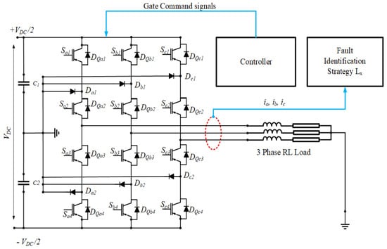
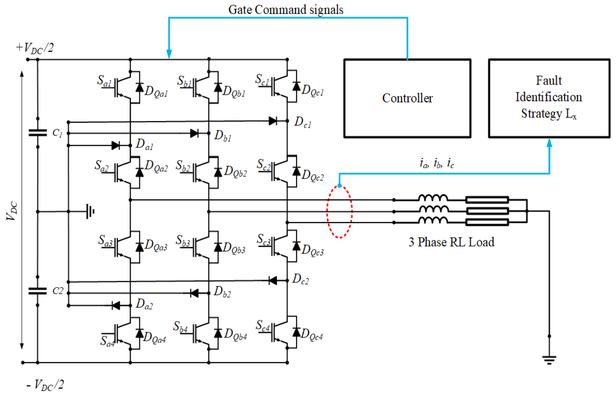
The system under study comprises a DC voltage source , a three-level NPC inverter, and a three-phase RL load, as shown in Figure 1. The DC-link is formed by two series-connected capacitors and , each supporting approximately at , whose common junction defines the neutral point O. Each phase leg x () consists of four series-connected IGBTs –, each equipped with an antiparallel freewheeling diode, – and two clamping diodes and connecting the midpoint of the leg to the neutral point. The clamping diodes clamp the blocking voltage across each IGBT to .
Figure 1.
Topology of the three-level NPC inverter.
Each phase leg operates in one of three switching states (P, O, or N), corresponding to the output voltage levels , 0, and , respectively, as listed in Table 1. In state P, and are ON and the phase is connected to the positive DC rail. In state N, and are ON and the phase is connected to the negative DC rail. In both states, the clamping diodes carry no current. In state O, and are ON; conducts when and conducts when , clamping V in both sub-intervals. Any open-circuit failure of a clamping diode therefore affects the inverter solely through the loss of this zero-voltage clamping function.
Table 1.
Switching states of the three-level NPC inverter ().
The phase-voltage waveform generated by the PWM switching process consists of a fundamental component and high-frequency switching harmonics. The harmonic components originate from the switching action of the power devices and are attenuated by the RL load impedance. Since the fault analysis focuses on the fundamental-frequency behavior of the phase current, the high-frequency switching components are neglected, and only the fundamental component is retained. Under sinusoidal PWM modulation, the fundamental phase voltages are:
where is the peak amplitude of the fundamental voltage and is the fundamental angular frequency. Under normal operation, the three switching states P, O, and N produce a balanced three-level output. State O is essential to this balance, as it generates the zero-voltage level for each phase. The effect of a clamping diode open-circuit fault on state O is analyzed in the following subsection.
2.2. Open-Circuit Fault Mechanism and Phase Current Effect
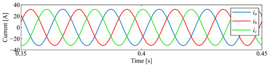
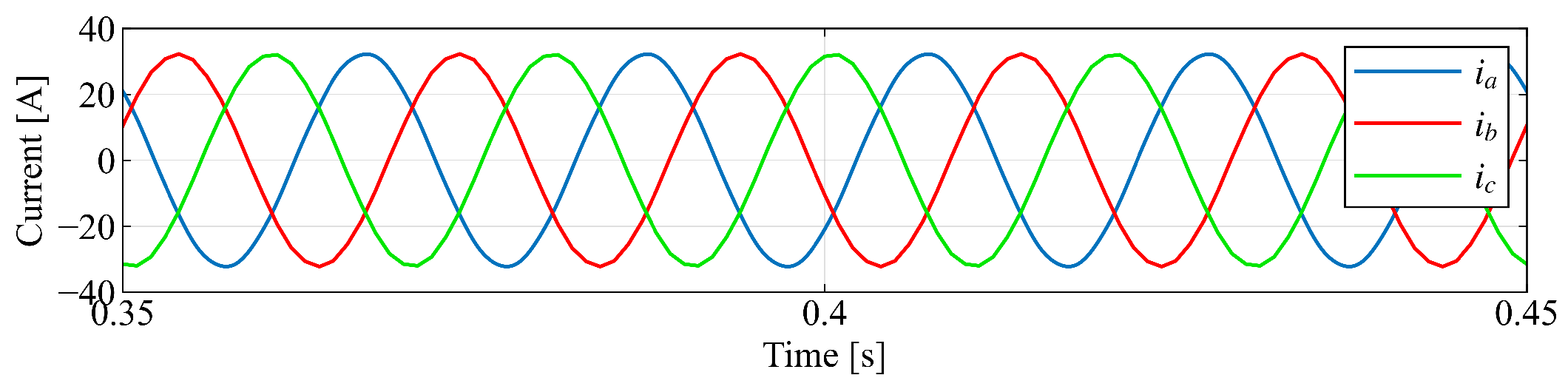
Under healthy conditions, the phase current of each leg exhibits half-wave symmetry, so its per-cycle mean value is approximately zero (Figure 2). Each phase leg x contains two clamping diodes: the upper diode , which conducts during state O when , and the lower diode , which conducts during state O when . An open-circuit fault in either diode eliminates one freewheeling path through the neutral point, disrupting the zero-voltage clamping function for the corresponding current polarity. This breaks the half-wave symmetry of the phase current and causes the per-cycle mean of to shift away from zero. The direction of the shift depends on which diode has failed.
Figure 2.
Phase current waveforms under healthy conditions.
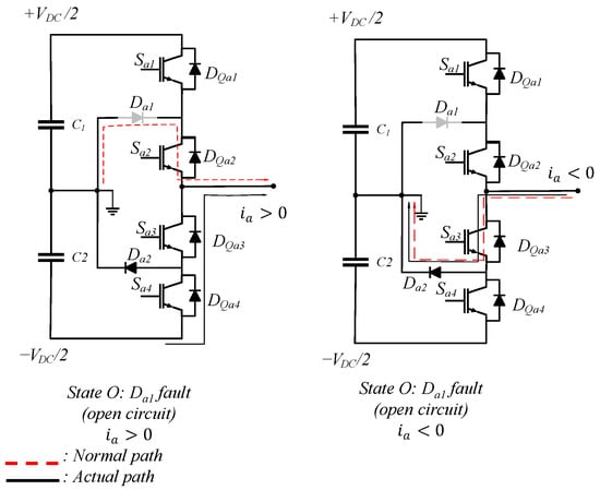
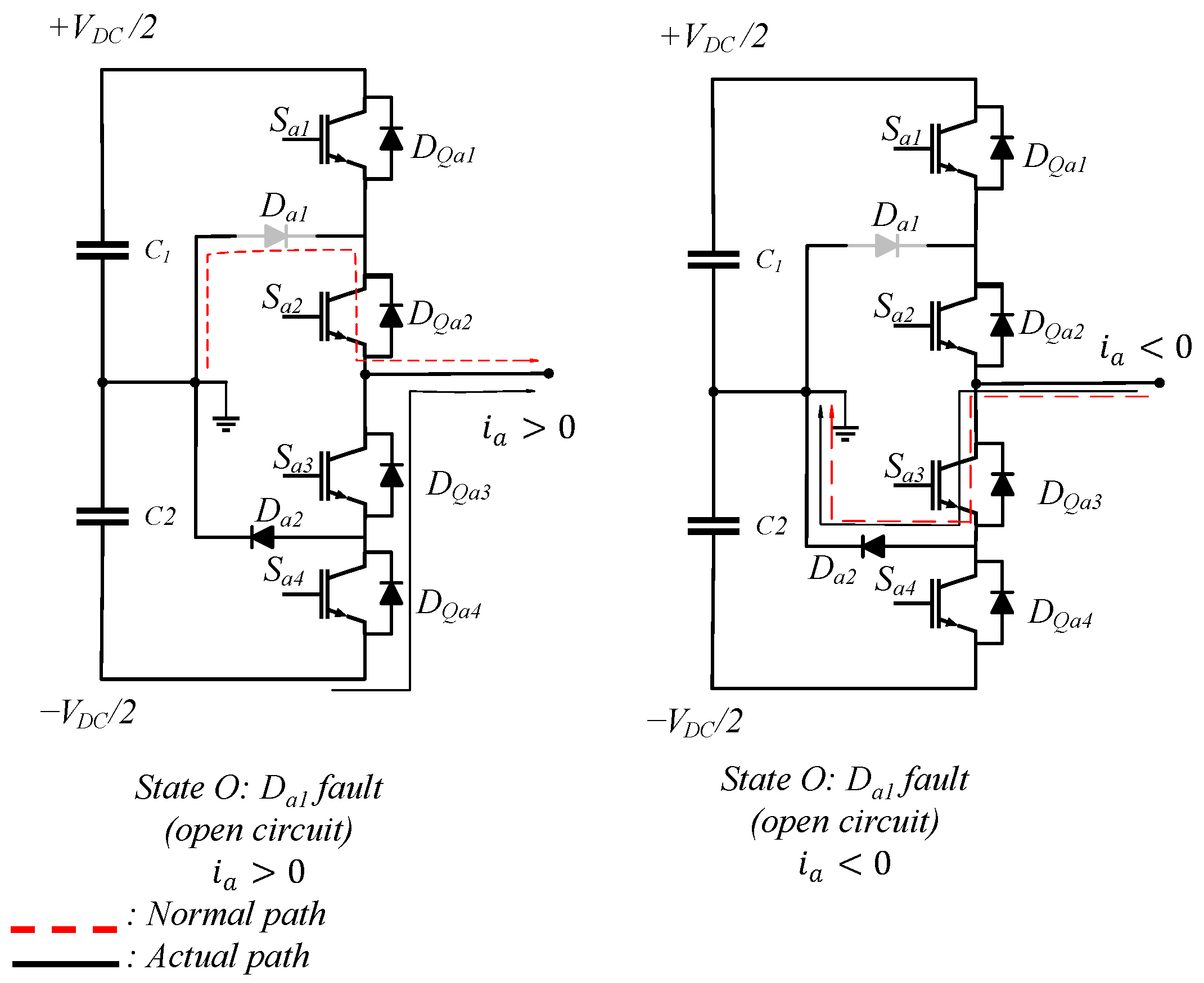
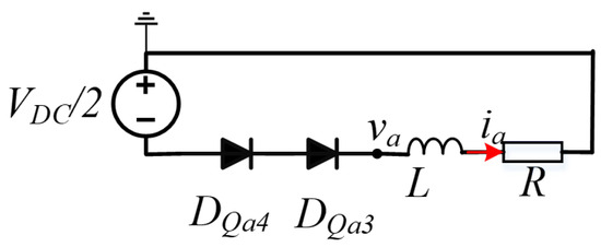
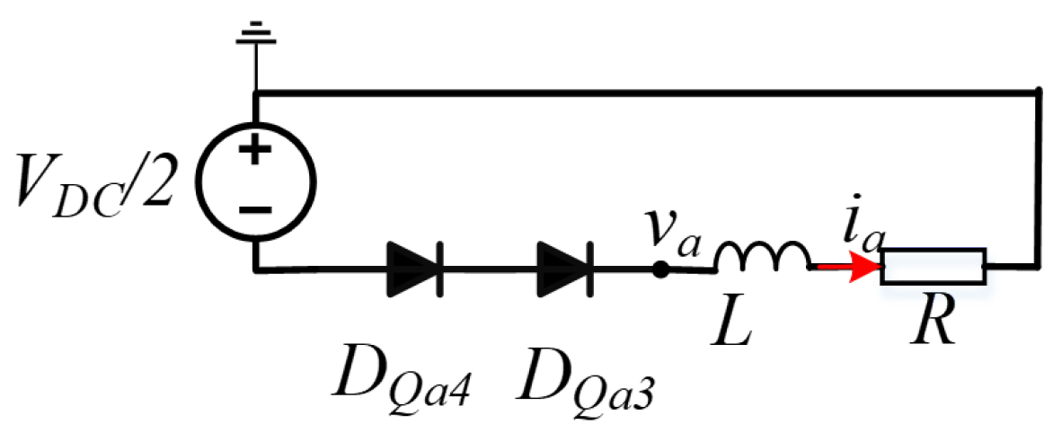
Without loss of generality, the fault mechanism is analyzed for phase A with an open-circuit fault in the upper clamping diode . When fails, the positive-freewheeling path through the neutral point is lost. As illustrated in Figure 3, during state O with , the phase current can no longer return through the neutral-point bus and is instead forced through the body diodes of and , effectively applying across the phase inductance.
Figure 3.
State O conduction paths of phase A.
The equivalent circuit for this transition is shown in Figure 4.
Figure 4.
Equivalent circuit of phase A during the P-to-O transition with open-circuited.
With initial phase current , the governing equation is:
Since the body diodes cease to conduct at zero current, the transient solution is:
where the integration constant A is determined from initial phase current.
Equation (3) shows that the fault suppresses the positive-current interval of state O from a maintained freewheeling level to an exponential decay toward zero. This reduces the positive half-cycle integral while leaving the negative half-cycle unaffected, so the per-cycle mean of becomes negative. A fault in the lower diode produces the symmetric effect: the negative-freewheeling interval is suppressed, and the per-cycle mean shifts to a positive value. The same mechanism applies identically to phases B and C. The resulting fault signatures for all cases are summarized in Table 2.
Table 2.
Fault signatures for clamping diode open-circuit failures.
3. Fault Diagnosis Method Based on Phase Current Asymmetry
3.1. Definition of the Asymmetry Index
As discussed in Section 2.2, a clamping diode open-circuit fault induces a deviation in the per-cycle mean phase current while having limited impact on the overall current magnitude. The use of mean current-based indicators for fault diagnosis in NPC inverters has been reported in [6,11]. In [6], a reactive current injection is introduced to enhance fault observability; however, this approach modifies the operating point of the converter and may not be suitable for grid-connected systems operating under unity power factor or MPPT control. In [11], a fault-assumption-based strategy is applied in rectifier configurations, which is not directly transferable to inverter-side photovoltaic systems.
Conventional indicators such as RMS value or peak current are also sensitive to load and irradiance variations, which limits their robustness under variable operating conditions. Therefore, an asymmetry index that is insensitive to amplitude variations while preserving sensitivity to waveform asymmetry is required.
In this paper, the normalized phase-current asymmetry () is quantified using the following index [23]:
where the per-cycle mean and absolute mean values are defined as:
The normalization by ensures that is bounded within and independent of the current amplitude. Under healthy conditions, the phase current exhibits half-wave symmetry, resulting in and thus . When a clamping diode open-circuit fault occurs, the loss of one freewheeling path introduces a bias in one half-cycle, causing a non-zero value of . The rate of change of is additionally evaluated to characterize the transient evolution of the asymmetry following a clamping-diode fault. The sign of indicates whether the upper or lower clamping diode is affected, as analyzed in Section 2.2.
3.2. Fault Diagnosis Procedure
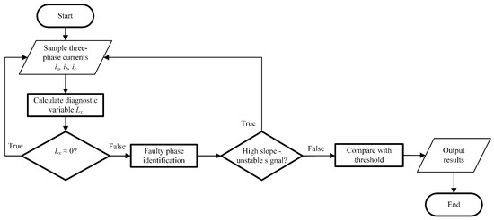
The fault diagnosis procedure consists of three sequential steps, as illustrated in the flowchart of Figure 5.
Figure 5.
Flowchart of the proposed fault diagnosis algorithm based on the asymmetry index.
- Step 1.
- Computation of the Asymmetry Index.
For each phase x, the asymmetry index is computed at the end of every fundamental period according to Equations (4) and (5). The calculation requires only the phase current , which is readily available from the existing inverter control sensors.
- Step 2.
- Transient Suppression via Slope Monitoring.
Upon the occurrence of a fault, the asymmetry index undergoes a transient excursion prior to settling to its steady-state post-fault value. To prevent false alarms during this transient period, the algorithm evaluates the magnitude of the slope of . A large slope indicates that the signal has not yet stabilized; under this condition, the diagnostic output is suppressed. Once the slope falls below a predefined threshold signifying that the signal has converged, the algorithm proceeds to the subsequent comparison stage. This approach effectively distinguishes transient disturbances from genuine faults, thereby improving detection robustness.
- Step 3.
- Threshold Comparison and Fault Declaration.
After the signal has stabilized, the asymmetry index is compared against a predefined positive threshold as follows:
- –
- : no open-circuit fault is detected in the clamping diodes of phase x.
- –
- : open-circuit fault of the upper clamping diode in phase x.
- –
- : open-circuit fault of the lower clamping diode in phase x.
The diagnostic result is then output, which completes the procedure for the current evaluation cycle.
The proposed method requires no additional sensors, no hardware modifications, and no perturbation of the nominal operating point. As all computations involve only per-cycle averaging and a simple slope evaluation, the algorithm is well suited for direct implementation on standard digital signal processor (DSP) or field-programmable gate array (FPGA) platforms commonly employed in inverter control systems.
4. Simulation Results and Discussion
4.1. Simulation Setup
Simulations were performed in MATLAB/Simulink R2021 to verify the proposed diagnostic method. The three-level NPC inverter was modeled with ideal switches and sinusoidal PWM with a triangular carrier. The system was operated under stable steady-state conditions before a clamping diode open-circuit fault was introduced at s. The control strategy was kept unchanged after the fault to isolate its effects on the phase current and on . The simulation parameters are listed in Table 3.
Table 3.
Simulation parameters.
Table 3 lists the electrical parameters of the simulated system, corresponding to a typical 10 kW medium-voltage drive. These parameters define the baseline operating condition used to evaluate all fault cases discussed in the following subsections.
4.2. Upper Clamping Diode Fault: Open-Circuit
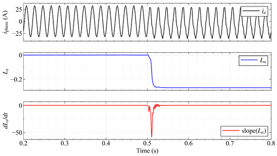
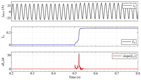
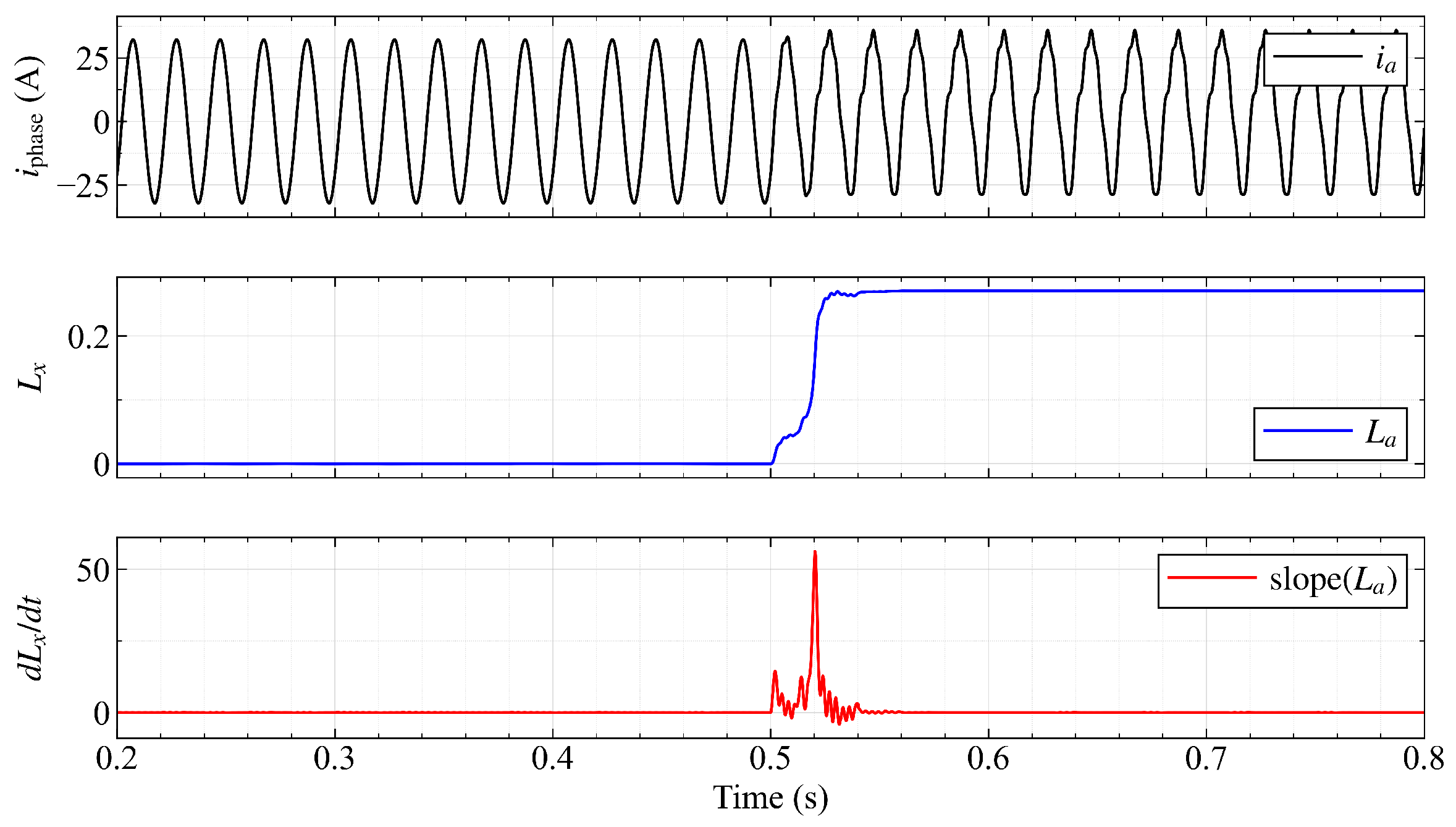
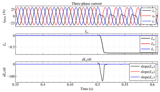
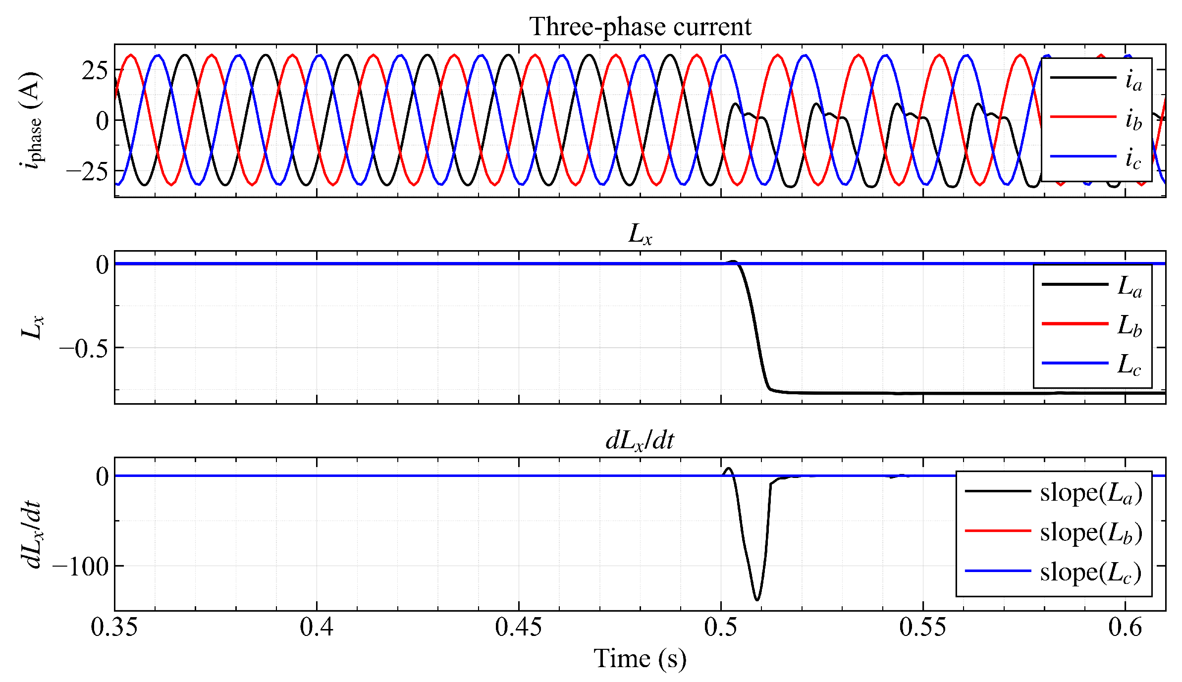
Figure 6 presents the phase A current waveform and the asymmetry index following an open-circuit fault of at s. Prior to the fault, remains consistently close to zero, confirming half-wave symmetric operation. At fault onset, decreases rapidly and converges to a stable negative value within approximately 1.5 fundamental cycles, clearly exceeding the negative threshold . The large rate of change immediately following the fault activates the rate-based detection at Step 2, while the sustained threshold crossing over cycles provides the definitive fault declaration at Step 3. The negative sign of unambiguously identifies the upper clamping diode on phase A as the failed element, consistent with the theoretical predictions in Table 2.
Figure 6.
Phase A current waveform (top) and asymmetry index (bottom) upon open-circuit fault of upper clamping diode at s.
4.3. Lower Clamping Diode Fault: Open-Circuit
Figure 7 presents the results for an open-circuit fault of the lower clamping diode . In this case, increases to a stable positive value within a comparable convergence time, consistent with the suppression of the negative-freewheeling interval established in Section 2.2. The positive sign of correctly identifies as the failed element. The symmetry between Figure 6 and Figure 7 confirms the validity of the analytical fault signature model.
Figure 7.
Phase A current waveform (top) and asymmetry index (bottom) upon open-circuit fault of lower clamping diode at s.
4.4. Generalization to All Three Phases
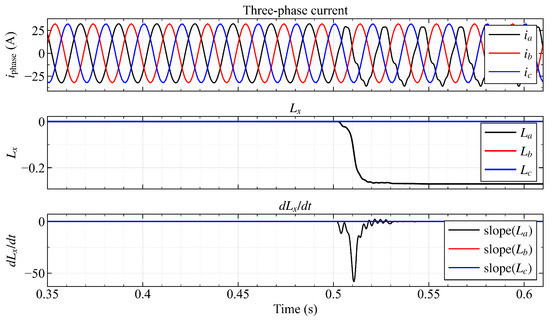
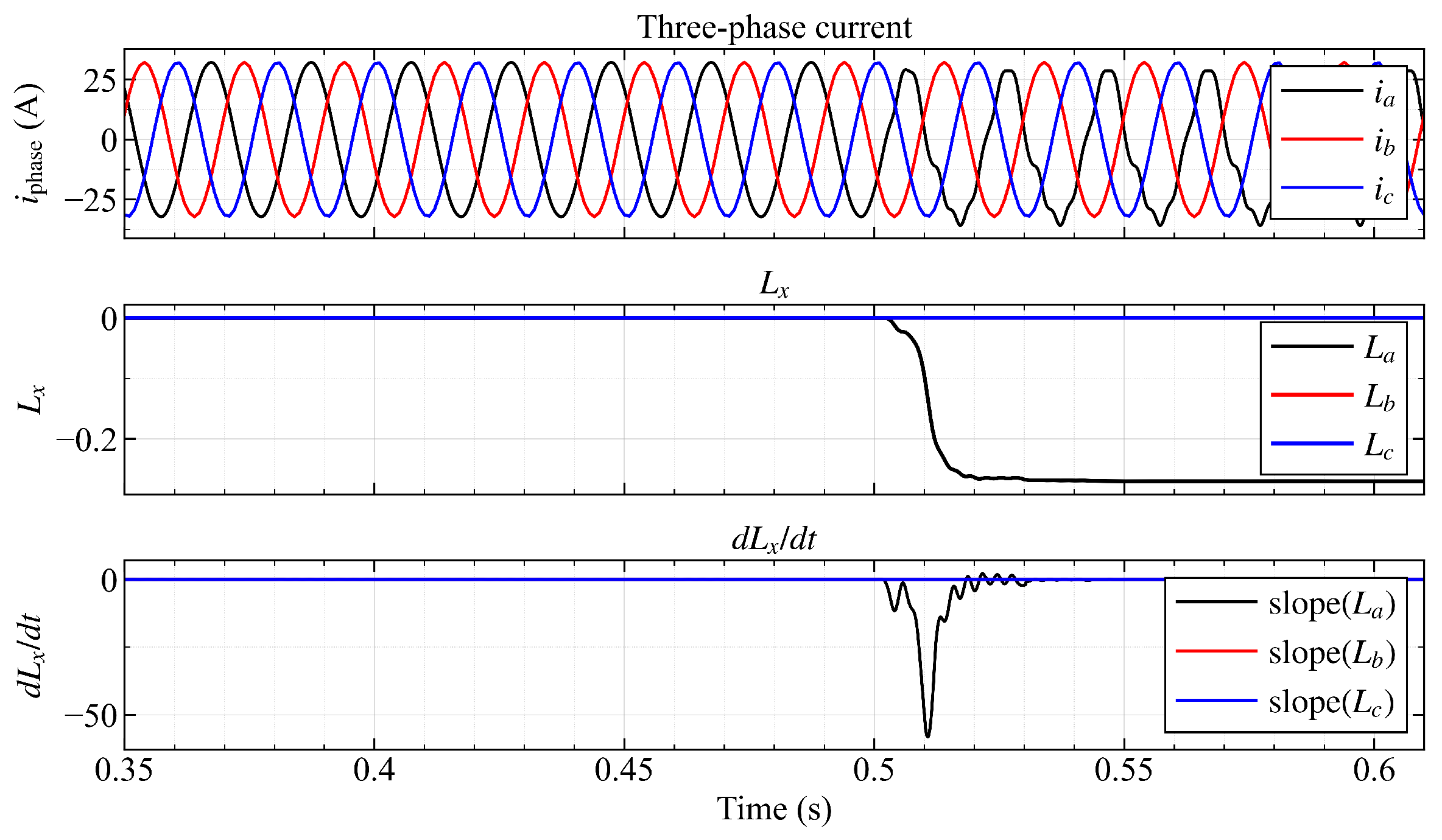
Figure 8 presents the asymmetry indices , , and when an open-circuit fault is introduced on the upper clamping diode of phase A () at s. Prior to the fault, all three indices remain near zero. Following the fault, departs toward a stable negative value while and remain unaffected. The faulted phase and the position of the failed diode are thus unambiguously identified by the sign and location of the deviation. These results confirm correct single-phase localization with a detection time of approximately 1–2 fundamental cycles across all tested fault scenarios.
Figure 8.
Asymmetry indices , , and upon open-circuit fault of upper clamping diode (phase A) at s; only deviates, confirming unambiguous single-phase fault localization.
Figure 9 presents the response of to an open-circuit fault of the upper IGBT under identical operating conditions. Although also deviates from zero, its steady-state magnitude and initial slope are both noticeably larger than those observed for the fault. This difference suggests that clamping diode and IGBT open-circuit faults produce distinguishable asymmetry index signatures; however, a rigorous discrimination criterion is beyond the scope of the present work.
Figure 9.
Asymmetry indices , , and upon open-circuit fault of upper IGBT (phase A) at s.
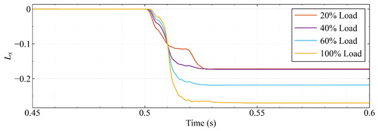
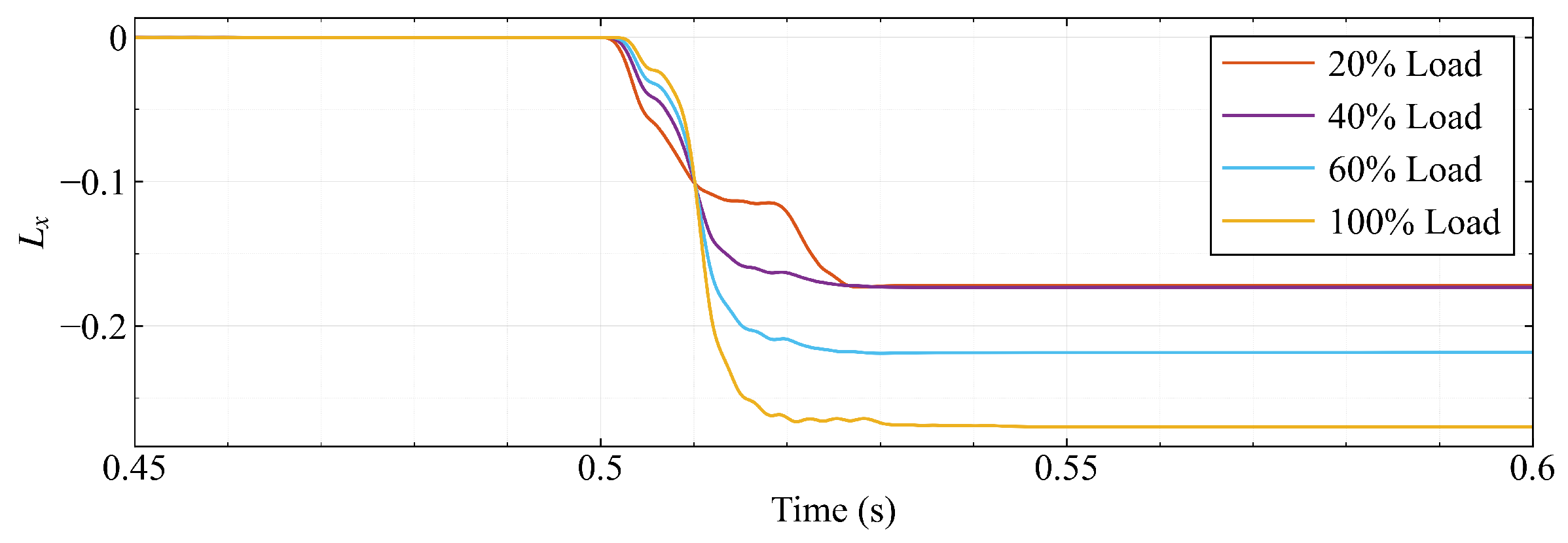
It is also noted that the steady-state value of is dependent on the load resistance and inductance. As a result, the detection threshold must be adjusted according to the operating load condition: for each load level, a corresponding threshold value of is determined through simulation. Figure 10 shows the variation of under open-circuit fault of for different load conditions, confirming that each load level yields a distinct steady-state value of the asymmetry index. Both fault-type discrimination between clamping diodes and IGBTs, and load-adaptive threshold selection, are reserved for future investigation.
Figure 10.
Steady-state value of under open-circuit fault of upper clamping diode for different load conditions.
5. Conclusions
This paper has proposed a clamping diode open-circuit fault diagnosis method for three-level NPC inverters based on a current asymmetry index , defined as the ratio of the per-cycle mean phase current to the per-cycle mean of its absolute value. The index remains near zero under healthy conditions and shifts to a non-zero value upon a fault, with its sign identifying the failed diode. The method uses only the phase currents already available in the control system, requiring no additional sensors or hardware modifications. Simulation results for a 10 kW three-level NPC inverter confirm detection and localization of both upper and lower clamping diode open-circuit faults within approximately 1–2 fundamental cycles for all three phases, in agreement with the analytical fault signature model.
Future work will address two limitations: the steady-state value of is load-dependent, motivating a load-adaptive threshold scheme, and IGBT open-circuit faults also deviate from zero, motivating a dedicated criterion to discriminate clamping diode faults from IGBT faults.
Author Contributions
Conceptualization, T.A.D. and T.T.C.; methodology, T.A.D. and H.-G.V.; software, T.A.D. and N.H.M.; validation, T.A.D., T.T.C., H.-G.V. and N.H.M.; formal analysis, T.A.D. and N.H.M.; investigation, T.A.D. and N.H.M.; data curation, T.A.D. and N.H.M.; writing—original draft preparation, T.A.D.; writing—review and editing, T.T.C., H.-G.V. and N.H.M.; visualization, T.A.D.; supervision, T.T.C. and H.-G.V.; project administration, T.A.D. All authors have read and agreed to the published version of the manuscript.
Funding
This research received no external funding.
Institutional Review Board Statement
Not applicable.
Informed Consent Statement
Not applicable.
Data Availability Statement
The authors confirm that the data supporting the findings of this study are available within the article.
Conflicts of Interest
The authors declare no conflicts of interest.
Abbreviations
The following abbreviations are used in this manuscript:
| DSP | Digital Signal Processor |
| FPGA | Field-Programmable Gate Array |
| HVDC | High-Voltage Direct Current |
| IGBT | Insulated Gate Bipolar Transistor |
| MPPT | Maximum Power Point Tracking |
| NPC | Neutral-Point-Clamped |
| PV | Photovoltaic |
| PWM | Pulse Width Modulation |
| RMS | Root Mean Square |
| THD | Total Harmonic Distortion |
References
- Nabae, A.; Takahashi, I.; Akagi, H. A new neutral-point-clamped PWM inverter. IEEE Trans. Ind. Appl. 1981, IA-17, 518–523. [Google Scholar] [CrossRef] [Scilit]
- Rodríguez, J.; Bernet, S.; Wu, B.; Pontt, J.O.; Kouro, S. Multilevel voltage-source-converter topologies for industrial medium-voltage drives. IEEE Trans. Ind. Electron. 2007, 54, 2930–2945. [Google Scholar] [CrossRef] [Scilit]
- Kouro, S.; Malinowski, M.; Gopakumar, K.; Pou, J.; Franquelo, L.G.; Wu, B.; Rodríguez, J.; Pérez, M.A.; Leon, J.I. Recent advances and industrial applications of multilevel converters. IEEE Trans. Ind. Electron. 2010, 57, 2553–2580. [Google Scholar] [CrossRef] [Scilit]
- Teichmann, R.; Bernet, S. A comparison of three-level converters versus two-level converters for low-voltage drives, traction, and utility applications. IEEE Trans. Ind. Appl. 2005, 41, 855–865. [Google Scholar] [CrossRef] [Scilit]
- Rodríguez, J.; Bernet, S.; Steimer, P.K.; Lizama, I.E. A survey on neutral-point-clamped inverters. IEEE Trans. Ind. Electron. 2010, 57, 2219–2230. [Google Scholar] [CrossRef] [Scilit]
- Choi, U.-M.; Jeong, H.-G.; Lee, K.-B.; Blaabjerg, F. Method for detecting an open-switch fault in a grid-connected NPC inverter system. IEEE Trans. Power Electron. 2012, 27, 2726–2739. [Google Scholar] [CrossRef] [Scilit]
- Alili, A.; Al Ameri, A.; Camara, M.B.; Dakyo, B. Open-circuit fault detection method for grid-side three-level NPC inverter. In Proceedings of the 10th International Conference on Renewable Energy Research and Applications (ICRERA), Istanbul, Turkey, 26–29 September 2021; pp. 120–124. [Google Scholar]
- Selvakumar, P.; Muthukumaran, G. A three-level NPC inverter fault detection and identification using voltage vector residual evaluation based on current path tracking method. e-Prime—Adv. Electr. Eng. Electron. Energy 2024, 8, 100541. [Google Scholar] [CrossRef] [Scilit]
- Smith, C.; Gargoom, A.; Arif, M.T.; Haque, M.E. Model predictive control of 3L-NPC inverter to enhance fault ride through capability under unbalanced grid conditions. IET Power Electron. 2024, 17, 1973–1985. [Google Scholar] [CrossRef] [Scilit]
- Chen, M.; He, Y. Multiple open-circuit fault diagnosis method in NPC rectifiers using fault injection strategy. IEEE Trans. Power Electron. 2022, 37, 8554–8571. [Google Scholar] [CrossRef] [Scilit]
- Chen, M.; He, Y. Open-circuit fault diagnosis method in NPC rectifiers using fault-assumed strategy. IEEE Trans. Power Electron. 2022, 37, 13668–13683. [Google Scholar] [CrossRef] [Scilit]
- Kou, L.; Liu, C.; Cai, G.; Zhou, J.; Yuan, Q.; Pang, S. Fault diagnosis for open-circuit faults in NPC inverter based on knowledge-driven and data-driven approaches. IET Power Electron. 2020, 13, 1236–1245. [Google Scholar] [CrossRef] [Scilit]
- Mimouni, A.; Laribi, S.; Bizhani, H.; Iwanski, G. Switch fault diagnosis of grid-connected inverter using symmetrical components. IEEE J. Emerg. Sel. Top. Power Electron. 2024, 12, 5258–5272. [Google Scholar] [CrossRef] [Scilit]
- de la Rosa-Mendoza, S.J.; Alvarez-Salas, R.; Gonzalez-Garcia, M.A.; Espinosa-Perez, G. Open-circuit switch fault diagnosis of an NPC converter in a DFIG-based WECS. Electr. Power Syst. Res. 2026, 252, 112410. [Google Scholar] [CrossRef] [Scilit]
- Yan, Y.; Wu, J.; Cao, Y.; Liu, B.; Li, C.; Shi, T. An open-circuit fault diagnosis method for three-level neutral point clamped inverters based on multi-scale shuffled convolutional neural network. Sensors 2024, 24, 1745. [Google Scholar] [CrossRef] [Scilit] [PubMed]
- Liu, S.; Qian, X.; Wan, H.; Ye, Z.; Wu, S.; Ren, X. NPC three-level inverter open-circuit fault diagnosis based on adaptive electrical period partition and random forest. J. Sens. 2020, 2020, 9206579. [Google Scholar] [CrossRef] [Scilit]
- Han, S.; Zhang, S.; Lv, W. Fault diagnosis of grid-connected NPC inverter based on information fusion and lightweight neural network. Electr. Power Syst. Res. 2025, 247, 111835. [Google Scholar] [CrossRef] [Scilit]
- Zhang, W.; Guan, B.; Chang, Y. Two-step process-based open-circuit fault diagnosis for three-level NPC converters. Electronics 2025, 14, 542. [Google Scholar] [CrossRef] [Scilit]
- Zhang, Y.; Li, Z.; Chen, H.; Huang, H.; Chen, G.; Zhang, M.; Zhang, Z. A unified fast open-circuit fault diagnosis method for 3L-NPC power converters. IEEE Trans. Power Electron. 2025, 41, 5739–5752. [Google Scholar] [CrossRef] [Scilit]
- Choi, U.-M.; Lee, J.-S.; Blaabjerg, F.; Lee, K.-B. Open-Circuit Fault Diagnosis and Fault-Tolerant Control for a Grid-Connected NPC Inverter. IEEE Trans. Power Electron. 2016, 31, 7234–7247. [Google Scholar] [CrossRef] [Scilit]
- Zhang, G.; Li, M.; Gu, X.; Chen, W. Fault diagnosis method for open-circuit faults in NPC three-level inverter based on WKCNN. CES Trans. Electr. Mach. Syst. 2025, 9, 234–245. [Google Scholar] [CrossRef] [Scilit]
- Avina-Corral, V.; Rangel-Magdaleno, J.J.; Barron-Zambrano, J.H.; Rosales-Nunez, S. Review of fault detection techniques in power converters: Fault analysis and diagnostic methodologies. Measurement 2024, 234, 114864. [Google Scholar] [CrossRef] [Scilit]
- Patel, K.; Borole, S.; Manikandan, R.; Singh, R.R. Short Circuit and Open Circuit Fault Identification Strategy for 3-Level Neutral Point Clamped Inverter. In Proceedings of the 2021 Innovations in Power and Advanced Computing Technologies (i-PACT), Kuala Lumpur, Malaysia, 27–29 November 2021; pp. 1–6. [Google Scholar]

Disclaimer/Publisher’s Note: The statements, opinions and data contained in all publications are solely those of the individual author(s) and contributor(s) and not of MDPI and/or the editor(s). MDPI and/or the editor(s) disclaim responsibility for any injury to people or property resulting from any ideas, methods, instructions or products referred to in the content. |
© 2026 by the authors. Licensee MDPI, Basel, Switzerland. This article is an open access article distributed under the terms and conditions of the Creative Commons Attribution (CC BY) license.