


Abstract
Autonomous acoustic sensing systems are increasingly investigated for unmanned aerial vehicle (UAV)-based surveillance and environmental monitoring applications due to their passive operation and relatively low computational requirements. However, the integration of acoustic classification and direction-of-arrival estimation on UAV-mounted microphone arrays remains challenging, particularly because realistic flight conditions introduce propulsion noise, aerodynamic flow, vibration, and complex acoustic interference. This paper presents a static ground validation of an AI-assisted acoustic target detection and azimuth estimation framework integrated on a flying-wing vertical take-off and landing (VTOL) UAV equipped with a distributed microphone array. The proposed system combines MFCC-based chainsaw sound classification using a Random Forest model with amplitude-based and SRP-PHAT-based azimuth estimation. Four HiFiBerry measurement microphones were mounted on a 4 m wingspan flying-wing VTOL UAV and connected to a Raspberry Pi 5 processing unit. Experimental validation was conducted under controlled indoor laboratory conditions using loudspeaker playback, with the UAV propulsion system inactive and only the acoustic acquisition and processing subsystem powered. The tests included single-source angular measurements, simultaneous multi-source acoustic scenarios, and source height variation. The SRP-PHAT method achieved a mean angular error of 3.55° in the single-source tests and 4.81° in the multiple-source tests, outperforming the amplitude-based baseline. The results support the feasibility of the proposed acoustic-processing framework under static ground conditions. However, because propulsion noise and in-flight aerodynamic effects were not included in the present validation, future work must address simulated propulsion noise injection, propulsion-on static testing, outdoor validation with real chainsaw sources, and eventual in-flight experiments. Because propulsion noise, aerodynamic flow, and in-flight vibration were not included in the present experimental campaign, the results should be interpreted as baseline static ground validation results rather than evidence of in-flight robustness.
1. Introduction
The rapid evolution of autonomous unmanned aerial vehicle (UAV) systems has significantly expanded the operational capabilities of aerial platforms across environmental monitoring, infrastructure inspection, surveillance, disaster assessment, and defense-related applications [1,2,3,4]. In particular, flying-wing vertical take-off and landing (VTOL) UAV configurations have attracted considerable interest because they combine the aerodynamic efficiency and endurance of fixed-wing aircraft with the operational flexibility of rotary-wing systems [5,6]. These hybrid architectures are especially suitable for long-endurance autonomous missions performed in remote or infrastructure-limited environments where real-time situational awareness and onboard decision-making capabilities are essential [7].
Among the sensing technologies currently integrated into UAV systems, acoustic sensing has emerged as an attractive complementary solution due to its passive operation, low power requirements, and capability to operate under visually degraded or radio-frequency-denied conditions [8,9,10]. Unlike electro-optical systems, acoustic sensing is less affected by illumination variations, smoke, vegetation occlusion, or adverse weather conditions [11]. In addition, distributed microphone arrays provide spatial acoustic awareness capabilities that allow not only sound detection and classification, but also sound localization and directional estimation through time-difference-of-arrival (TDOA) processing and beamforming techniques [12,13,14,15].
Recent advances in microphone miniaturization and embedded processing architectures have enabled the integration of compact distributed acoustic sensing systems directly onboard UAV platforms [16]. Multiple studies have investigated the use of Micro-Electro-Mechanical System (MEMS) microphones for aerial acoustic monitoring due to their low mass, reduced power consumption, and suitability for distributed sensing architectures [17,18]. Beamforming approaches based on minimum variance distortionless response (MVDR), generalized sidelobe canceling (GSC), and adaptive filtering techniques have demonstrated improved sound-source isolation capabilities under noisy operating conditions [19,20,21]. Similarly, sound localization methods such as generalized cross-correlation with phase transform (GCC-PHAT), steered response power phase transform (SRP-PHAT), and MUSIC-based approaches remain widely employed for acoustic direction-of-arrival (DOA) estimation in distributed microphone systems [22,23,24,25].
The increasing availability of embedded artificial intelligence (AI) accelerators has also transformed acoustic event classification for UAV applications. Deep-learning architectures operating on spectrogram-based representations have demonstrated superior performance compared with traditional machine-learning approaches relying on handcrafted acoustic features [26]. Convolutional neural networks (CNNs), convolutional recurrent neural networks (CRNNs), and transformer-based acoustic models have been successfully applied for environmental sound classification, UAV detection, and anomalous acoustic event recognition [27,28,29,30,31]. Data augmentation techniques such as SpecAugment, time masking, pitch shifting, and synthetic noise injection have further improved model robustness under low signal-to-noise ratio (SNR) conditions [32,33]. In parallel, lightweight embedded inference architectures have enabled real-time onboard acoustic classification on low-power platforms including Raspberry Pi and NVIDIA Jetson systems [34,35].
Beyond algorithmic accuracy, the deployment of AI-based sensing systems on UAVs requires the simultaneous consideration of embedded hardware architecture, power consumption, latency, payload integration, and operational reliability. Recent intelligent UAV platforms have therefore increasingly adopted hardware–software co-design approaches, in which perception, onboard processing, energy management, and flight-control interfaces are considered as interconnected subsystems rather than independent modules. For example, recent work on AI-enhanced UAV design has addressed the integration of embedded electronics, propulsion, LiPo energy storage, AI-based navigation, sensor monitoring, and power-aware operation under wind and payload disturbances. Such studies highlight that embedded intelligence for UAVs must be evaluated not only in terms of algorithmic performance, but also with respect to computational feasibility, power budget, real-time processing constraints, and compatibility with the airframe and flight-control architecture [36].
Despite the significant progress achieved in acoustic detection and classification, UAV-based acoustic systems continue to face major operational challenges. One of the primary limitations is represented by propulsion-induced self-noise generated by electric motors and propellers, which significantly degrades externally acquired acoustic signals [37,38,39]. This issue becomes particularly critical for VTOL UAV configurations, where multiple propulsion systems produce broadband and tonal interference components that overlap spectrally with mission-relevant sound signatures [39]. Additional challenges include aerodynamic turbulence, vibration coupling, environmental reverberation, directional ambiguity, and reduced localization accuracy under dynamic operating conditions [40,41,42,43].
Recent studies have investigated acoustic localization and tracking systems for UAV applications under both static and dynamic scenarios. Multi-sensor fusion frameworks combining acoustic sensing with radio-frequency (RF), electro-optical, or inertial measurements have demonstrated improved robustness and target discrimination capabilities. Furthermore, distributed microphone arrays have been explored for autonomous sound-source localization in robotic systems and environmental monitoring platforms. However, the majority of existing works primarily focus on sound detection, sound classification, or acoustic localization independently, without addressing higher-level autonomous decision-making processes.
More specifically, current UAV acoustic systems are generally limited to identifying or localizing acoustic events, while the autonomous interpretation and prioritization of multiple simultaneous sound sources remain insufficiently explored. In realistic operational environments, UAVs may encounter complex acoustic scenes involving multiple overlapping sound events with varying levels of mission relevance. More specifically, current UAV acoustic systems are generally limited to identifying or localizing acoustic events, while the integration of acoustic perception outputs into higher-level UAV decision-support architectures remains insufficiently explored. In realistic operational environments, UAVs may encounter complex acoustic scenes involving multiple overlapping sound events with different levels of relevance. However, before autonomous prioritization or navigation responses can be reliably implemented, the basic detection and azimuth estimation performance of UAV-mounted acoustic arrays must first be validated under controlled conditions. The present work therefore focuses on chainsaw-specific acoustic detection and azimuthal direction estimation, while the development and optimization of mission-level prioritization weights is treated as future work.
Although acoustic classification and localization methods have been widely investigated, the integration of these methods on UAV-mounted acoustic arrays still requires staged validation before operational deployment. In particular, static ground testing is necessary to evaluate the basic classification and azimuth estimation behavior of the system using the real microphone geometry of the UAV platform, before introducing additional interference sources such as propeller noise, aerodynamic flow, and in-flight vibration.
Therefore, this paper presents a static ground validation of an AI-assisted acoustic target detection and azimuth estimation framework integrated on a 4 m wingspan flying-wing VTOL UAV. The proposed system combines MFCC-based chainsaw sound classification with SRP-PHAT-based direction-of-arrival estimation using a distributed four-microphone array mounted directly on the UAV airframe. The objective of this study is to evaluate the feasibility of the acoustic-processing pipeline under controlled laboratory conditions, using the real UAV mounting geometry but without propulsion activation or in-flight operation. The validation focuses on single-source angular accuracy, chainsaw detection in simultaneous multi-source acoustic scenarios, and the influence of source height on azimuth estimation. The remaining steps required for preliminary/static ground validation toward future UAV autonomy, including propulsion noise robustness, outdoor testing, and in-flight validation, are explicitly discussed as future work.
2. Materials and Methods
2.1. UAV Platform and Static Experimental Configuration
The experimental platform used in this study was a flying-wing vertical take-off and landing (VTOL) unmanned aerial vehicle (UAV) with a wingspan of approximately 4 m. The platform was selected as the integration structure for the acoustic sensing system because its geometry allows the microphones to be distributed over a relatively large baseline, which is beneficial for direction-of-arrival estimation. The flying-wing configuration also provides representative integration constraints for acoustic sensing applications on UAVs, including distributed mounting positions, structural shadowing effects, and practical limitations related to cable routing and onboard processing hardware placement.
The acoustic system was integrated directly on the UAV airframe using four spatially distributed measurement microphones connected to an onboard processing unit. The UAV center of mass was used as the reference origin for defining the microphone coordinates and the angular convention adopted in the direction estimation algorithm. In this convention, 0° corresponds to the forward direction of the UAV, 90° to the right side, 180° to the rear direction, and 270° to the left side. The detailed microphone geometry and acquisition parameters are presented in Section 2.2.
All validation tests reported in this work were conducted under static laboratory conditions. During these tests, the UAV was used as a fixed structural platform for mounting the distributed acoustic array, while the propulsion system remained inactive. Therefore, the reported results should be interpreted as static UAV-mounted acoustic validation tests rather than propulsion-on or in-flight validation tests. Only the acoustic acquisition and processing subsystem was powered during the experiments. This configuration allowed the evaluation of the classification and direction estimation pipeline under controlled laboratory conditions, while preserving the real mounting geometry and integration constraints of the UAV platform.
The onboard processing architecture was based on a Raspberry Pi 5, which was used to acquire the microphone recordings, execute the chainsaw-specific acoustic classification model, compute the direction-of-arrival estimates, and log the resulting detection and localization outputs. The complete processing chain was designed to support real-time operation, although the present validation focused on controlled static experiments using loudspeaker playback of predefined acoustic signals.
From an embedded-system perspective, the acoustic module was organized as a dedicated perception payload installed on the UAV airframe. The Raspberry Pi 5 acted as the local processing unit for acoustic acquisition, AI inference, direction estimation, visualization, and data logging. The flight platform and the acoustic-processing module were treated as functionally separate subsystems during the present validation: the UAV airframe provided the representative mounting geometry, while the acoustic subsystem operated independently from the propulsion and flight-control loops. This separation was intentional because the present work focused on validating the acoustic-processing chain under controlled static conditions before closing the loop with UAV navigation or propulsion-on operation.
The main embedded-design constraints considered during this initial implementation were low payload complexity, compatibility with the available UAV structure, low computational burden, and the possibility of future integration with flight-control commands. For this reason, the classifier was implemented using MFCC features and a Random Forest model rather than a larger deep-learning architecture. The direction estimation stage was implemented using a 500–5000 Hz band-pass filter, GCC-PHAT pairwise correlations, and a 1° SRP-PHAT azimuth scan. This configuration was selected as a computationally lightweight solution suitable for execution on Raspberry Pi 5 (Raspberry Pi Ltd., Cambridge, UK) without an external GPU accelerator.
The embedded architecture and integration constraints of the UAV-mounted acoustic-processing module are summarized in Table 1, while the flying-wing VTOL UAV platform and the general microphone-array installation are shown in Figure 1.
Table 1.
Embedded architecture and integration constraints of the UAV-mounted acoustic-processing module.
Figure 1.
Flying-wing VTOL UAV platform used for static acoustic-system integration, showing the general configuration of the distributed microphone array installation on the airframe.
2.2. Distributed Microphone Array Geometry and Acoustic Acquisition
The acoustic acquisition system consisted of four HiFiBerry measurement microphones mounted on the UAV airframe. The microphones were distributed around the UAV center of mass in order to provide spatial acoustic information for azimuthal direction-of-arrival estimation. The coordinate origin was defined at the UAV center of mass, with the positive (x)-axis oriented toward the right side of the UAV and the positive (y)-axis oriented toward the forward direction. Using this convention, the front direction of the UAV corresponds to 0°, the right side to 90°, the rear direction to 180°, and the left side to 270°. The microphone-array geometry and the angular reference convention used for the static laboratory tests are illustrated in Figure 2.
Figure 2.
Experimental microphone array geometry and angular reference system used during the static laboratory tests. The image shows the UAV underside, the circular azimuth reference, and the approximate microphone positions relative to the UAV center of mass.
The microphone locations were measured relative to the UAV center of mass and implemented in the direction estimation algorithm. All microphones were mounted at approximately the same vertical level; therefore, only the horizontal coordinates were considered in the localization model. The resulting array was treated as a planar microphone configuration intended for azimuthal sound-source direction estimation. The microphone coordinates used for the UAV-mounted acoustic array are presented in Table 2.
Table 2.
Microphone coordinates used for the UAV-mounted acoustic array.
The microphone distribution was not perfectly symmetric in the longitudinal direction because the mounting positions were constrained by the UAV airframe geometry. This measured geometry was used directly in the direction estimation calculations, rather than assuming an ideal circular or square array. The lateral baseline between Mic 2 and Mic 4 was 2.00 m, while the longitudinal distance between Mic 1 and Mic 3 was 1.05 m. This configuration provided a larger spacing in the lateral direction, while preserving a usable front–rear baseline for estimating the azimuthal direction of acoustic sources.
Each microphone recorded the acoustic signal as an individual mono audio waveform stored in WAV format. The acquisition and processing sampling rate was set to 22.05 kHz, matching the sampling rate of the WAV-format recordings used during validation. The four microphone signals were subsequently processed by the onboard acoustic system to perform chainsaw-specific sound classification and direction-of-arrival estimation. The four microphones were connected as independent USB audio devices and each channel was stored as a separate mono audio waveform in WAV format. The WAV format preserves the time-domain waveform of each individual channel; however, because the microphones were not connected through a hardware-synchronized multichannel acquisition device, the acquisition system did not guarantee sample-level synchronization between channels. The recordings were acquired using the same sampling rate, checked for sampling-rate compatibility, and trimmed to a common signal length before localization processing. Nevertheless, no dedicated inter-channel clock-drift correction or time-offset calibration was applied during the present validation campaign. Consequently, the relative timing and phase relationship between microphone channels may contain small synchronization errors, which can affect GCC-PHAT and SRP-PHAT localization accuracy. A synchronized multi-channel acquisition architecture, such as a four-channel analog-to-digital converter with simultaneous sampling, would provide a more appropriate hardware basis for phase-based localization because it would preserve inter-channel timing relationships more accurately. The present USB-based implementation was selected as a low-cost, rapidly deployable configuration for initial static ground validation, while synchronized acquisition hardware is planned for future system development. Since the microphone array was approximately planar, the system was designed to estimate the azimuthal bearing of the acoustic source rather than its full three-dimensional position. Consequently, the system does not estimate source range or elevation and should not be interpreted as a complete three-dimensional acoustic localization system. The estimated azimuth represents a directional cue toward the acoustic source in the horizontal plane, not a full source position.
The static experimental tests were conducted indoors in a laboratory environment. The acoustic sources were reproduced using loudspeaker playback and were positioned at an approximate horizontal distance of 0.5 m from the UAV center of mass, depending on the specific test configuration. This short-range configuration was selected to provide a controlled and repeatable baseline validation of the classification and azimuth estimation pipeline using known source angles and the real UAV-mounted microphone geometry. It should not be interpreted as representative of the source distances expected during real outdoor UAV search missions. No long-range outdoor acoustic measurements were included in the present validation campaign.
2.3. Acoustic Dataset and Chainsaw-Specific AI Classifier
The acoustic recognition module was developed as a binary sound-event classifier designed to distinguish chainsaw-specific acoustic signatures from non-specific environmental and mechanical sounds. The target class consisted of 220 chainsaw recordings, while the non-target class consisted of more than 900 non-specific recordings, including music, human voices, electric drills, and other background acoustic events. This binary formulation was selected because the objective of the system was not general sound-scene classification, but the identification of a predefined acoustic target relevant to UAV-based monitoring applications.
All audio samples were stored as WAV-format audio recordings and processed using the same sampling rate adopted for the experimental acquisition system, namely 22.05 kHz. Prior to feature extraction, each audio signal was converted to a mono waveform and normalized in amplitude in order to reduce the influence of recording-level variations between samples. The classification features were extracted using Mel-Frequency Cepstral Coefficients (MFCCs), which provide a compact representation of the spectral envelope of an acoustic signal and are commonly used for mechanical-sound recognition tasks.
The MFCC–Random Forest architecture was selected as a lightweight and interpretable classification solution suitable for the initial embedded implementation on Raspberry Pi 5. Although deep-learning models such as CNNs, CRNNs, and Transformer-based audio classifiers represent the current state of the art in general environmental sound classification, their effective training and validation usually require larger and more diverse datasets, higher computational resources, and more extensive hyperparameter optimization. In the present study, the available dataset was limited to 220 chainsaw-specific recordings and more than 900 non-specific recordings, and the main objective was to validate the complete UAV-mounted acoustic-processing pipeline rather than to perform a comparative benchmark of sound-classification architectures. Therefore, the MFCC–Random Forest model was adopted as a computationally efficient baseline that could provide probabilistic chainsaw detection while maintaining compatibility with low-power onboard processing.
Let denote the discrete-time acoustic signal used for classifier input. Since environmental and mechanical sounds are non-stationary, the signal was analyzed over short-time frames using the Short-Time Fourier Transform (STFT):
where is the analysis window, is the hop size, is the frame index, is the frequency-bin index, and is the frame length. The corresponding magnitude spectrogram was obtained as:
The magnitude spectrum was subsequently projected onto a Mel filter bank. The Mel-frequency scale was defined as:
For each Mel band , the filter-bank energy was computed as:
where represents the -th triangular Mel filter. Logarithmic compression was then applied in order to reduce the dynamic range of the spectral representation:
where is a small numerical constant introduced to avoid the logarithm of zero. Finally, Discrete Cosine Transform (DCT) was applied to the log-Mel energies to obtain the MFCC vector:
where is the -th MFCC coefficient and is the number of Mel bands. In the implemented classifier, 20 MFCCs were extracted and averaged over time, resulting in a fixed-length feature vector for each analyzed audio sample.
The classifier was implemented using a Random Forest model trained to separate chainsaw and non-chainsaw acoustic events. The labeled dataset can be written as:
where is the MFCC feature vector extracted from the -th audio sample, denotes the chainsaw class, denotes the non-chainsaw class, and is the total number of samples. The dataset was divided using an 80/20 train-test split. The Random Forest classifier was trained using 100 decision trees, and the final model output was expressed as a posterior probability associated with the chainsaw class:
During system operation, the classifier was applied independently to the recordings acquired from each microphone. The maximum chainsaw probability obtained across the four microphones was used as the detection indicator for the analyzed recording:
where represents the chainsaw probability estimated for microphone . A chainsaw event was considered detected when .
Therefore, the detection threshold used in the validation tests was set to 80%. This probability-based output was also useful for interpreting uncertain cases, including false negatives in which the acoustic source corresponded to a chainsaw signal, but the estimated probability remained below the detection threshold.
The summary of the acoustic dataset and classifier configuration is presented in Table 3.
Table 3.
Summary of the acoustic dataset and classifier configuration.
The classifier configuration was selected for embedded feasibility and initial target-class validation. A quantitative comparison with CNN, CRNN, Transformer, or pretrained audio foundation models was not performed in the present study and is identified as future work.
The trained classifier was integrated into the onboard acoustic-processing pipeline and used as the first decision layer of the system. Its role was to determine whether a chainsaw-specific sound was present in the analyzed acoustic scene. The direction-of-arrival estimation methods, described in the following subsections, were then used to estimate the azimuthal bearing of the detected or dominant acoustic source.
2.4. Real-Time Acoustic Processing Workflow
The onboard acoustic-processing workflow was designed to combine chainsaw-specific sound recognition with azimuthal direction-of-arrival estimation using the four-microphone array mounted on the UAV structure The main processing stages are summarized in Figure 3, while the graphical user interface developed for experimental operation and visualization is shown in Figure 4. The system starts from four independent mono audio waveform recordings stored in WAV format, which are then processed through two complementary branches. The classification branch determines whether the target acoustic class is present, while the localization branch estimates the azimuthal direction of the dominant acoustic source. This architecture allows the system to provide both a detection decision and a directional output for the analyzed acoustic scene.
Figure 3.
Simplified acoustic-processing workflow implemented on the UAV-mounted system. The diagram summarizes the four-channel audio acquisition stage, the MFCC-based chainsaw classification branch, the SRP-PHAT-based azimuth estimation branch, and the final post-processing outputs used for visualization, logging, and manual labeling.
Figure 4.
Graphical user interface developed for the UAV-mounted acoustic-analysis system. The interface includes recording controls, detection-status indicators, microphone-level chainsaw probabilities, SRP-PHAT and amplitude-based direction estimation outputs, directional-sector information, confidence indicators, console output, and spectrogram panels for the four microphones.
To improve readability, Figure 3 presents only the main functional blocks of the acoustic-processing pipeline, while the detailed mathematical formulation of the classification and direction estimation stages is provided in Section 2.3 and Section 2.5.
The first stage of the workflow consists of synchronized acquisition from the four microphones installed on the UAV airframe. Each microphone signal is stored as an individual WAV-format audio recording and subsequently loaded by the onboard processing unit. Before analysis, the signals are converted to mono format, checked for compatible sampling rate and duration, and trimmed to a common signal length. This preprocessing step ensures that all microphone channels are analyzed over the same time interval, which is necessary for reliable inter-microphone comparison and direction estimation.
The classification branch uses the MFCC-based Random Forest model described in Section 2.3. For each microphone signal, MFCC features are extracted and passed through the trained classifier. The classifier outputs a chainsaw probability for each microphone channel:
where represents the probability that the acoustic signal recorded by microphone belongs to the chainsaw class. The final chainsaw detection indicator is based on the maximum probability among the four microphones .
A chainsaw event is considered detected when .
This decision rule was selected because the sound source may be more strongly represented in one or two microphones depending on its azimuthal position, source directivity, and acoustic shadowing from the UAV structure. Therefore, using the maximum microphone-level probability allows the system to detect the target sound even when the source is not equally captured by all microphones.
In parallel with the classification branch, the direction estimation branch processes the four microphone recordings to estimate the azimuthal bearing of the acoustic source. Prior to localization, the signals are band-pass filtered in the 500–5000 Hz frequency range using a fourth-order Butterworth filter. This frequency range was selected to emphasize mechanical acoustic components relevant to chainsaw-like sounds while reducing low-frequency background components and high-frequency noise. The filtered signals are then used for two direction estimation approaches: a rough amplitude-based method and the main SRP-PHAT-based method.
The amplitude-based method computes the band-limited root mean square (RMS) value of each microphone signal and estimates a rough bearing based on the relative energy distribution across the array. This output is retained as a diagnostic and comparison method rather than as the primary localization result. The main direction estimation output is obtained using GCC-PHAT pairwise correlations and SRP-PHAT angular scanning. The SRP-PHAT method evaluates candidate azimuth angles over a 360° search space with a resolution of 1°, using the measured microphone coordinates defined in Section 2.2. The implementation also includes candidate elevation values to reduce azimuthal bias caused by sources located outside the microphone plane; however, the system output is limited to azimuthal direction estimation and is not interpreted as full three-dimensional localization.
The SRP-PHAT branch produces a raw azimuth angle, a selected elevation candidate used internally during the scan, a localization score, and a confidence indicator. The raw azimuth angle is then smoothed using a circular averaging procedure in order to avoid discontinuities around the 0°/360° boundary. The smoothed angle is mapped to a directional sector for simplified interpretation. The eight sectors used by the system are North, North-East, East, South-East, South, South-West, West, and North-West, corresponding to the angular convention defined for the UAV-mounted array.
The final system output includes the chainsaw detection state, the maximum chainsaw probability, the microphone-level chainsaw probabilities, the SRP-PHAT raw and smoothed angles, the selected directional sector, the SRP-PHAT confidence value, the amplitude-based rough angle, and the band-limited RMS values for all four microphones. These values are stored in an Excel log file for post-processing and experimental evaluation. This logging mechanism was used to generate the validation tables analyzed in the Results section.
The acoustic-processing pipeline was also implemented in a graphical user interface to support experimental operation, visualization, and manual data labeling. The interface allowed the operator to start and stop the acquisition process, monitor the classification and localization outputs, inspect the microphone-level detection probabilities, and visualize the spectrograms associated with the four microphone channels. This implementation was useful during the validation campaign because it provided direct access to both the classification outputs and the direction estimation results generated by the onboard processing workflow.
The graphical interface displayed the main acoustic-analysis outputs, including the final detection result, the highest detected amplitude, the SRP-PHAT angle of arrival, the raw SRP-PHAT angle, the amplitude-based rough angle, the estimated directional sector, the SRP-PHAT confidence value, the selected elevation candidate, and the chainsaw probability estimated for each microphone. A console-output area was also included to provide real-time feedback during the recording and processing sequence.
In addition to visualization, the interface included manual labeling controls that allowed newly recorded samples to be categorized as chainsaw or non-chainsaw events. This feature was implemented to support dataset expansion and future retraining of the acoustic classifier. Therefore, the GUI served as an experimental support layer for recording, monitoring, labeling, and validating the acoustic-processing workflow.
Although the graphical interface is not the main scientific contribution of the study, it demonstrates that the proposed acoustic-processing pipeline was implemented in an operational form suitable for laboratory testing and future real-time UAV monitoring applications. The main methodological contribution remains the integration of chainsaw-specific acoustic classification with UAV-mounted microphone array direction estimation.
From a computational perspective, the implementation was designed for execution on a Raspberry Pi 5 without the use of an external GPU accelerator. The main processing tasks consisted of loading four microphone recordings, extracting MFCC features for chainsaw classification, applying band-pass filtering, computing GCC-PHAT correlations for the six available microphone pairs, scanning the SRP-PHAT azimuth grid, smoothing the resulting angle, and logging the output parameters The use of MFCC features, a Random Forest classifier, and a 1° SRP-PHAT azimuth scan provided a computationally lightweight implementation suitable for laboratory real-time operation on Raspberry Pi 5, without requiring GPU acceleration or the larger memory and processing resources typically associated with deep neural audio classifiers. This design avoided the higher computational and power requirements associated with larger deep-learning models, while preserving sufficient functionality for the present static validation. However, detailed benchmarks of CPU load, memory usage, processing latency, and energy consumption were not performed in the present study. Consequently, the current work should be considered a functional embedded implementation rather than a complete embedded-system optimization study. Future work will include systematic profiling of processing latency, power draw, and resource utilization, especially before propulsion-on and in-flight implementation.
It is important to note that the present implementation uses the classification and direction estimation branches as complementary modules. The AI classifier determines whether the acoustic event corresponds to the predefined chainsaw target class, while the SRP-PHAT method estimates the azimuthal direction of the acoustic source from the microphone array signals. Therefore, the method is described in this work as an AI-assisted chainsaw detection and SRP-PHAT-based direction estimation framework, rather than as a fully probability-weighted SRP-PHAT formulation. This distinction ensures that the methodological description remains consistent with the implemented validation pipeline.
The present implementation does not use an optimized multi-criteria weighted prioritization function. Instead, the decision logic is based on a predefined chainsaw-probability threshold, SRP-PHAT azimuth estimation, confidence estimation, circular smoothing, and sector mapping. The 80% probability threshold was used as a conservative criterion for target-class detection during the static validation tests. Parameters such as classification confidence, temporal persistence, directional stability, and target relevance are relevant for future mission-level prioritization, but their relative weights were not statistically optimized or validated in the present study.
2.5. Direction-of-Arrival Estimation Methods
The acoustic direction-of-arrival estimation stage was implemented using two complementary methods. The first method was an amplitude-based bearing estimator, used as a simple diagnostic and baseline approach. The second method was a phase-based SRP-PHAT estimator, used as the main azimuth estimation method. Both methods used the measured microphone coordinates defined in Section 2.2 and followed the same angular convention: 0° corresponds to the forward direction of the UAV, 90° to the right side, 180° to the rear direction, and 270° to the left side.
The use of two direction estimation methods allowed the experimental results to compare a simple energy-based approach with a more robust phase-based method. The amplitude-based method is computationally inexpensive but sensitive to microphone gain differences, acoustic shadowing, source distance, and reflections. In contrast, SRP-PHAT uses inter-microphone time-delay information and is therefore more directly linked to the physical geometry of the microphone array. The two methods were applied to the same recordings and compared in the Results Section.
2.5.1. Amplitude-Based Direction Estimation
The amplitude-based method estimates the approximate bearing of the acoustic source using the relative band-limited energy measured by the four microphones. Before computing the amplitude-based angle, each microphone signal was filtered in the same frequency range used for the SRP-PHAT localization stage, namely 500–5000 Hz. This range was selected to emphasize mechanical acoustic components and reduce the influence of unrelated low-frequency and high-frequency noise.
For the signal recorded by microphone , the root mean square amplitude was computed as:
where is the band-pass-filtered signal recorded by microphone , and is the number of analyzed samples. The resulting amplitude values were used as weights associated with the known microphone positions. Let denote the position vector of microphone , and let denote the geometric center of the microphone array:
where is the number of microphones. A rough source-direction vector was then computed as:
The amplitude-based azimuth angle was obtained using the four-quadrant inverse tangent function:
where and are the components of . The result was converted to degrees and wrapped to the interval :
This method assumes that the microphone receiving the highest acoustic energy is generally closer to, or more directly exposed to, the sound source. However, this assumption is only approximate. In practice, the received amplitude may be affected by microphone sensitivity differences, airframe shadowing, loudspeaker directivity, indoor reflections, and small changes in source position. For this reason, the amplitude-based result was retained as a rough comparison method and was not considered the primary direction-of-arrival estimate.
2.5.2. SRP-PHAT-Based Direction Estimation
The main direction estimation method was based on Steered Response Power with Phase Transform weighting. This method estimates the source azimuth by scanning a set of candidate directions and selecting the direction that best matches the inter-microphone time-delay structure observed in the recordings. The implementation used GCC-PHAT correlations between all microphone pairs, followed by SRP-PHAT angular scanning over the full 360° azimuth domain.
Before the GCC-PHAT calculation, all microphone signals were band-pass filtered between 500 Hz and 5000 Hz using a fourth-order Butterworth filter. This frequency band was used to preserve relevant mechanical acoustic content while reducing very-low-frequency components and high-frequency noise. The speed of sound was assumed to be .
For each microphone pair , the Fourier transforms of the corresponding filtered signals were denoted by and . The cross-power spectrum was computed as:
where denotes complex conjugation. The PHAT weighting normalizes the magnitude of the cross-power spectrum so that the correlation is based primarily on phase information:
where is a small numerical constant introduced to avoid division by zero. The GCC-PHAT correlation function was then obtained by applying the inverse Fourier transform:
where is the candidate time delay between microphones and . In the implemented system, a GCC interpolation factor of 8 was used in order to improve the delay resolution.
For a candidate azimuth angle , the unit vector pointing from the microphone array center toward the sound source was defined as:
where is a candidate elevation angle. Since the microphone array is approximately planar, the elevation angle was not used to report a three-dimensional source position. Instead, a limited set of elevation candidates was included only to reduce azimuthal bias when the loudspeaker source was not exactly in the microphone plane. The tested elevation candidates were .
For each microphone pair , the expected time difference of arrival associated with a candidate direction was computed as:
where and are the measured microphone coordinates, is the speed of sound, and represents the optional time-offset calibration term between microphones. The terms were included in the mathematical formulation to account for possible inter-channel latency offsets between independent USB microphones. In the present experimental implementation, these calibration terms were set to zero because no dedicated synchronization calibration was performed before the reported tests. Therefore, the SRP-PHAT estimates were obtained using the measured microphone geometry and common-length recordings, but without explicit compensation for possible USB clock or latency mismatch. This aspect represents a known limitation of the current hardware implementation and is further discussed in Section 4.
The SRP-PHAT score for each candidate direction was obtained by summing the GCC-PHAT responses evaluated at the predicted time delays:
where is the set of all microphone pairs and is the SRP-PHAT score associated with the candidate azimuth and elevation candidate . Since four microphones were used, six microphone pairs were available for the SRP-PHAT scan. The azimuth search was performed over the full 360° range with a resolution of 1°: .
The estimated azimuth was selected as the candidate angle that maximized the SRP-PHAT score:
The corresponding elevation candidate was stored as an internal parameter of the scan, but the reported localization output remained the azimuth angle . Therefore, the proposed method should be interpreted strictly as a two-dimensional azimuthal direction-of-arrival estimator, not as a full three-dimensional acoustic localization method. The output provides only a bearing direction in the horizontal plane. It does not provide source range, altitude, or absolute source coordinates. The elevation candidates used during the SRP-PHAT scan were included only to reduce azimuthal bias caused by out-of-plane source positions and were not used as valid elevation estimates.
A confidence indicator was computed from the SRP-PHAT score distribution in order to quantify how clearly the selected direction was separated from the remaining candidate directions. If is the maximum SRP-PHAT score, is the median score over the scan grid, and is the standard deviation of the score distribution, the confidence indicator was computed as:
where is the maximum SRP-PHAT score, is the median score over the scan grid, and is the standard deviation of the score distribution.
The value was clipped to the interval , where higher values indicate a more clearly defined SRP-PHAT maximum.
To reduce angular fluctuations between successive measurements, the raw SRP-PHAT angle was smoothed using a circular mean. For a set of recent angle estimates , the smoothed angle was calculated as:
where is the smoothed azimuth angle, represents the -th recent SRP-PHAT angle estimate, and is the number of values used in the circular smoothing window.
The result was converted to degrees and wrapped to the interval . In the implementation, a maximum history length of 10 angle estimates was used. Finally, the smoothed angle was mapped to one of eight directional sectors: North, North-East, East, South-East, South, South-West, West, and North-West.
The SRP-PHAT method was used as the primary direction estimation result because it relies on inter-microphone time-delay consistency rather than on amplitude differences alone. The amplitude-based estimate was retained as a comparative baseline, allowing the experimental results to quantify the improvement obtained by the phase-based method. The implementation parameters, including the 500–5000 Hz band-pass range, GCC interpolation factor, 1° azimuth scan resolution, elevation candidate scan, confidence calculation, circular smoothing, and sector mapping, were extracted from the implemented processing workflow.
2.6. Experimental Validation Protocol
The experimental validation campaign was designed to evaluate the performance of the UAV-mounted acoustic system under controlled static laboratory conditions. The UAV was positioned as a fixed test platform, with the acoustic subsystem powered and the propulsion system inactive. The sound sources were reproduced using loudspeaker playback and positioned at known angular locations relative to the UAV center of mass. The reference angular convention was the same as that used by the localization algorithm: 0° corresponded to the forward direction of the UAV, 90° to the right side, 180° to the rear direction, and 270° to the left side.
No synthetic, recorded, or live UAV propulsion noise source was introduced during the present experimental campaign; therefore, the validation was intentionally limited to controlled static ground testing of the acoustic-processing framework.
The tests were conducted indoors in a laboratory environment in order to allow repeatable positioning of the sound source and controlled comparison between the reference angle and the estimated angle. The approximate horizontal distance between the sound source and the UAV center of mass was 0.5 m. This distance was selected to ensure repeatable near-field laboratory measurements and to isolate the behavior of the classification and azimuth estimation algorithms under controlled geometric conditions. Therefore, the experimental protocol should be interpreted as a short-range static validation setup and not as a representative long-range outdoor UAV search scenario. No outdoor measurements with real chainsaw sources at larger distances were performed in the present study. For each test, the four microphone signals were recorded as individual WAV-format audio recordings and processed by the onboard acoustic pipeline. The resulting outputs included the microphone-level chainsaw probabilities, maximum chainsaw probability, chainsaw detection decision, SRP-PHAT raw angle, SRP-PHAT smoothed angle, SRP-PHAT confidence, amplitude-based rough angle, directional sector, and band-limited RMS values.
The validation was divided into three experimental blocks: a single-source angular accuracy test, a multiple-source acoustic discrimination test, and a source height variation test. The first test evaluated the angular accuracy of the two localization methods over different azimuthal positions. The second test evaluated whether the classifier could identify the chainsaw-specific sound in the presence of simultaneous competing acoustic sources. The third test investigated the effect of source height on azimuthal direction estimation, considering the planar nature of the microphone array.
The validation campaign consisted of 37 measurement trials in total. The single-source angular accuracy test included 22 trials, the multiple-source acoustic discrimination test included 6 trials, and the source height variation test included 9 trials. Each trial corresponded to one recorded experimental configuration, defined by source type, source position, angular reference, and, where applicable, source height. The measurements were therefore treated as controlled test cases distributed across different experimental conditions, rather than as repeated statistical replicates of the same identical condition. This distinction is important because the statistical indicators reported in the Results Section describe variability across the tested configurations and should not be interpreted as full repeatability analysis under identical repeated trials.
Table 4 presents the experimental validation matrix used for evaluating chainsaw detection and azimuthal direction-of-arrival estimation.
Table 4.
Experimental validation matrix used for evaluating chainsaw detection and azimuthal direction-of-arrival estimation.
2.6.1. Single-Source Angular Accuracy Test
The first validation block was designed to quantify the angular accuracy of the direction estimation methods. A single sound source was positioned at several known azimuth angles around the UAV, covering the four quadrants of the reference circle. This allowed the system to be evaluated across the complete 360° angular domain instead of only testing one preferred direction. Both chainsaw-specific and non-specific sounds were included in the test sequence in order to evaluate not only the angle-estimation behavior, but also the classifier response to target and non-target acoustic events.
For each angular position, the loudspeaker reproduced the selected acoustic signal while the four microphones recorded the resulting sound field. The recordings were then processed using both the amplitude-based method and the SRP-PHAT-based method described in Section 2.5. The known source angle was used as the reference value, while the two estimated angles were stored for comparison. This test was used to determine whether the SRP-PHAT method provided a more accurate azimuth estimate than the amplitude-based baseline.
The single-source test results should be presented later in the Results Section using the angular result plot from your third image.
2.6.2. Multiple-Source Acoustic Discrimination Test
The second validation block was designed to evaluate the behavior of the acoustic system when multiple sound sources were present simultaneously. In this test, chainsaw-specific sounds were played together with non-specific acoustic sources, such as human voices, music, electric drills, or other background sounds. The purpose of this test was to determine whether the AI classifier could still detect the chainsaw class in the presence of competing acoustic content.
Unlike the single-source angular test, the multiple-source test introduced overlapping acoustic signals. Therefore, the evaluation focused on the classifier’s ability to identify the predefined target class and on the direction estimation behavior under a more complex acoustic scene. For each test case, the system logged the microphone-level chainsaw probabilities, the maximum chainsaw probability, the detection decision, and the estimated angles from both localization methods.
A chainsaw detection was considered successful when the maximum chainsaw probability exceeded the 80% threshold. If the source corresponded to a chainsaw sound but the maximum probability remained below the threshold, the event was classified as a false negative. This terminology was used instead of false positive because the missed events corresponded to target-class sounds that were not detected with sufficient confidence.
2.6.3. Source Height Variation Test
The third validation block investigated the effect of source height on azimuthal direction estimation. This test was included because the microphone array was mounted approximately in a planar configuration on the UAV airframe. As a result, the system was designed primarily for azimuthal direction-of-arrival estimation and not for full three-dimensional acoustic localization.
During this test, the acoustic source was maintained at the same reference azimuth angle while its vertical position was varied. The same type of sound was used for each height condition, allowing the effect of vertical displacement to be evaluated independently from changes in source class. For each height, the system recorded the four microphone signals and computed both the SRP-PHAT-based angle and the amplitude-based rough angle.
The objective of this test was to determine whether changes in source height influenced the estimated azimuth angle. Since the SRP-PHAT algorithm includes a limited set of elevation candidates only as an internal correction mechanism, the selected elevation candidate was not interpreted as a true elevation estimate. Instead, the test was used to assess the sensitivity of the azimuthal result to out-of-plane source positions.
2.7. Evaluation Metrics
The experimental results were evaluated using separate metrics for the acoustic classification branch and the direction-of-arrival estimation branch. The classification branch was assessed based on the chainsaw detection probability and the resulting binary detection decision, while the localization branch was evaluated by comparing the estimated azimuth angle with the known reference angle used during the laboratory tests.
For the classification branch, the maximum chainsaw probability obtained from the four microphone channels was used as the main detection indicator
where is the chainsaw probability estimated for microphone . A chainsaw sound was considered detected when .
Based on this threshold, the classification outcome was assigned to one of the following categories. A true positive corresponded to a chainsaw sound correctly detected with . A false negative corresponded to a chainsaw sound for which . A true negative corresponded to a non-chainsaw sound correctly rejected by the classifier, while a false positive corresponded to a non-chainsaw sound incorrectly classified as chainsaw. In the present validation, this distinction was important because some missed chainsaw detections were identified as false negatives rather than false positives.
For the direction-of-arrival estimation branch, the estimated azimuth angle was compared with the known reference angle imposed during the experiment. Because angular quantities are circular, the localization error was computed using the minimum circular angular difference rather than a direct arithmetic difference. For a reference angle and an estimated angle , the circular angular error was calculated as:
This definition avoids artificial large errors near the 0°/360° boundary. For example, an estimated angle of 359° for a reference angle of 1° corresponds to a 2° error, not a 358° error.
The circular angular error was computed separately for the two direction estimation methods:
where is the SRP-PHAT-based azimuth estimate and is the amplitude-based azimuth estimate. This allowed a direct comparison between the main phase-based method and the simpler amplitude-based baseline.
For each experimental block, the localization performance was summarized using the mean angular error, median angular error, maximum angular error, and standard deviation of the angular error. For a set of tests, the mean absolute angular error was calculated as:
where is the circular angular error obtained for the -th test. The median error was used as an additional robust indicator because it is less sensitive to isolated high-error cases. The maximum error was also reported in order to identify the worst-case angular deviation observed during the validation tests.
In addition to the mean, median, maximum error, and standard deviation, a 95% confidence interval was calculated for the mean angular error of each method. The confidence interval was computed as:
where is the mean angular error, is the sample standard deviation of the angular error, is the number of trials, and is the critical value of the Student -distribution for degrees of freedom.
Because the SRP-PHAT and amplitude-based estimates were obtained from the same recordings, the comparison between the two methods was treated as a paired comparison. For each trial, the paired error difference was defined as:
where is the amplitude-based angular error and is the SRP-PHAT angular error for the -th trial. A paired -test was used as an exploratory statistical comparison between the two methods, while the results were interpreted cautiously because the number of trials was limited and the measurements represented different controlled configurations rather than repeated measurements of a single identical scenario.
For the single-source angular accuracy test, the main objective was to compare the SRP-PHAT estimated angle and the amplitude-based estimated angle against the imposed reference angle. Therefore, the primary metrics were the circular angular error, mean angular error, median angular error, maximum angular error, and standard deviation for each method.
For the multiple-source acoustic discrimination test, the evaluation considered both the chainsaw detection result and the estimated azimuth angle. A successful classification event required when the chainsaw sound was present. The localization result was then compared with the known angular position of the chainsaw source or the dominant target source used in the test. This allowed the system behavior to be evaluated under simultaneous competing acoustic sources.
For the source height variation test, the reference azimuth angle was kept constant while the vertical position of the loudspeaker was varied. The same circular angular error definition was used to evaluate how the SRP-PHAT and amplitude-based estimates changed as a function of source height. Since the microphone array was planar, this test was not used to validate elevation estimation. Instead, it was used to quantify the influence of source height on azimuthal localization accuracy.
Table 5 presents the evaluation metrics used for classification and direction-of-arrival assessment.
Table 5.
Evaluation metrics used for classification and direction-of-arrival assessment.
These metrics were used to compare the SRP-PHAT-based direction estimation method with the amplitude-based baseline and to assess the ability of the onboard acoustic system to detect chainsaw-specific sounds under controlled single-source, multiple-source, and source height variation conditions. The angular-error definition follows the circular-error formulation proposed in the algorithm documentation, while the detection metrics follow the probability-based classifier output used in the implemented processing pipeline.
No weighted multi-criteria prioritization score was included in the quantitative evaluation because such a score was not optimized in the present validation campaign. The reported evaluation therefore focuses on measurable classification and localization outputs: chainsaw probability, binary detection decision, circular angular error, mean error, median error, maximum error, and standard deviation.
Because no hardware synchronization or clock-drift compensation was applied, the angular-error metrics also reflect the combined influence of the localization algorithm, microphone geometry, indoor propagation effects, and possible inter-channel timing mismatch.
3. Results
The experimental results are presented according to the three validation blocks described in Section 2.6. First, the angular accuracy of the two direction estimation methods was evaluated using single-source tests distributed over the four quadrants of the reference circle. Second, the ability of the system to detect the chainsaw-specific acoustic class in the presence of simultaneous competing sounds was assessed. Finally, the influence of source height on azimuthal direction estimation was analyzed for a fixed reference angle.
Because the tests were conducted without simulated or real UAV propulsion noise, the results quantify the performance of the framework under static ground conditions and should not be interpreted as in-flight or propulsion noise robustness results.
The two direction estimation methods compared throughout this section are the amplitude-based method and the SRP-PHAT-based method. The amplitude-based method was treated as a baseline, while the SRP-PHAT method was considered the main direction-of-arrival estimation approach. The angular errors reported in this section were calculated using the circular angular error definition introduced in Section 2.7.
These results represent controlled static laboratory measurements and should therefore be interpreted as baseline performance indicators for the acoustic-processing framework. They do not include the effects of active UAV propulsion, aerodynamic flow, wind-induced microphone noise, structural vibration, or outdoor propagation effects, all of which may affect the classification and azimuth estimation performance under real operating conditions.
In addition, because the sound sources were positioned at approximately 0.5 m from the UAV center of mass, the reported angular and classification results represent short-range controlled baseline performance rather than long-range outdoor acoustic detection performance.
3.1. Single-Source Angular Accuracy Test
The first experimental block evaluated the angular accuracy of the acoustic localization system when a single sound source was active. The sound source was placed at known angular positions around the UAV, covering the four quadrants of the reference circle. A total of 22 single-source tests were performed. These tests included both chainsaw-specific and non-specific acoustic signals in order to evaluate the response of the classifier and the behavior of the direction estimation methods under different source classes.
The comparison between the reference source angle, the SRP-PHAT estimated angle, and the amplitude-based estimated angle for the single-source angular accuracy test is presented in Figure 5.
Figure 5.
Comparison between the reference source angle, the SRP-PHAT estimated angle, and the amplitude-based estimated angle for the single-source angular accuracy test.
The results show that the SRP-PHAT method followed the reference angle more closely than the amplitude-based method across the tested azimuth range. The SRP-PHAT estimates remained close to the imposed angular positions in all four quadrants, while the amplitude-based estimates showed larger deviations in several cases. This behavior was expected because the amplitude-based method depends strongly on relative microphone energy levels, which can be affected by airframe shadowing, microphone sensitivity differences, indoor reflections, and source directivity. A paired comparison between the two angular-error series showed that the SRP-PHAT method produced significantly lower angular errors than the amplitude-based method in the single-source test block . A non-parametric Wilcoxon signed-rank check led to the same interpretation . Therefore, within the tested single-source configurations, the improvement obtained by SRP-PHAT was not limited to one isolated favorable case.
The quantitative comparison between the two methods is summarized in Table 6.
Table 6.
Angular error statistics for the single-source angular accuracy test.
The SRP-PHAT method achieved a mean angular error of 3.55°, compared with 8.83° for the amplitude-based method. The median error was also lower for SRP-PHAT, with 2.85° compared with 7.19° for the amplitude-based approach. The largest observed SRP-PHAT error was 7.90°, while the amplitude-based method reached a maximum error of 29.46°. These results indicate that the phase-based method provided a more accurate and more consistent estimation of the acoustic source direction than the amplitude-based baseline.
From the classification perspective, the single-source test included 18 chainsaw-specific cases and 4 non-specific cases. Using the 80% detection threshold, the classifier correctly detected 13 of the 18 chainsaw-specific cases, while 5 chainsaw cases were classified as false negatives because the maximum chainsaw probability remained below the detection threshold. The four non-specific cases remained below the detection threshold and were therefore correctly rejected as non-chainsaw events.
The false negatives occurred at reference angles where the maximum chainsaw probability was close to, but below, the imposed 80% threshold. This suggests that the classifier response was affected not only by the sound class, but also by source position, microphone exposure, and the acoustic characteristics of the indoor laboratory environment.
3.2. Multiple-Source Acoustic Discrimination Test
The second experimental block evaluated the system under simultaneous multi-source acoustic conditions. In these tests, chainsaw-specific sounds were played together with one or more non-specific sounds, such as human voice, music, electric drill sounds, or other background acoustic content. The objective was to determine whether the AI classifier could still identify the chainsaw class when competing acoustic sources were present.
A total of 6 multiple-source tests were performed. In all cases, the sound sources were played simultaneously. The system logged the microphone-level chainsaw probabilities, the maximum chainsaw probability, the detection decision, and the estimated angles obtained using both the SRP-PHAT and amplitude-based methods.
The paired comparison for the multiple-source test block showed a consistent descriptive reduction in angular error for SRP-PHAT; however, the difference did not reach the conventional 0.05 significance level using a two-sided paired -test . This result should be interpreted cautiously because only six multiple-source trials were available. The observed reduction is encouraging, but additional repeated multi-source experiments are required before a strong statistical generalization can be made.
The angular-error statistics obtained for the multiple-source tests are presented in Table 7.
Table 7.
Angular error statistics for the multiple-source acoustic discrimination test.
The SRP-PHAT method again outperformed the amplitude-based approach. Under simultaneous multi-source conditions, the SRP-PHAT method achieved a mean angular error of 4.81°, while the amplitude-based method produced a mean error of 9.93°. The maximum SRP-PHAT error was 8.33°, whereas the maximum amplitude-based error reached 19.63°. These results indicate that the SRP-PHAT method retained better angular stability than the amplitude-based estimator when multiple acoustic sources were present.
From the classification perspective, the chainsaw sound was detected in 5 of the 6 multiple-source tests using the 80% probability threshold. One test produced a false negative, with the maximum chainsaw probability reaching 79%, just below the detection threshold. This result indicates that the classifier was generally able to identify the target acoustic class in the presence of competing sounds, although its decision remained sensitive to the selected threshold.
The multiple-source results should therefore be interpreted as controlled laboratory evidence that the acoustic system can detect a predefined target class under simultaneous competing sound conditions. However, these tests do not yet represent full real-world outdoor operation or in-flight validation, since the sound sources were reproduced using loudspeaker playback in an indoor laboratory environment.
3.3. Source Height Variation Test
The third experimental block evaluated the influence of the vertical position of the acoustic source on azimuthal direction estimation. This test was performed because the microphone array was mounted approximately in a planar configuration on the UAV airframe. As a result, the system was designed to estimate the azimuthal bearing of the source, while elevation was not treated as a directly measurable localization output.
During this test, the reference azimuth angle was maintained at 112°, while the loudspeaker height was varied relative to the laboratory floor. The tested heights ranged from 0 m to 2 m, where 0 m corresponded to floor level and 2 m approximately corresponded to the height of the microphone array plane. Therefore, the test evaluated how increasing vertical separation between the sound source and the microphone plane affected both classification confidence and azimuthal direction estimation.
The same chainsaw-specific sound was reproduced using loudspeaker playback for each height condition. The horizontal angular position of the source was kept constant, while only the vertical position of the loudspeaker was modified. This allowed the influence of source height to be evaluated independently from changes in azimuthal position.
The effect of height variation on angular behavior is presented in Figure 6.
Figure 6.
Influence of loudspeaker height above floor level on SRP-PHAT and amplitude-based azimuth estimation for a fixed reference angle of 112°. A height of 2 m approximately corresponds to the microphone array plane, while 0 m corresponds to floor level.
The results show that both the direction estimation accuracy and the chainsaw detection probability were affected by the vertical position of the source. When the loudspeaker was located close to the microphone array plane, the estimated angles were close to the reference value. For example, at 2 m, the SRP-PHAT estimate was 110.35°, while the amplitude-based estimate was 113.37°, both close to the imposed 112° reference angle. As the loudspeaker was lowered toward the floor, the angular deviation increased, particularly for the SRP-PHAT method at the lowest source positions.
Unlike the single-source and multiple-source tests, the source height variation test did not show a clear statistical advantage for either direction estimation method . This confirms that source height introduced a specific limitation for the planar microphone array configuration. Therefore, the height variation results should be interpreted primarily as a sensitivity analysis of the current array geometry rather than as evidence of general SRP-PHAT superiority under out-of-plane source conditions.
The height-test angular-error statistics are summarized in Table 8.
Table 8.
Angular error statistics for the source height variation test.
The SRP-PHAT method showed very good agreement with the reference angle when the source was approximately aligned with the microphone array height. However, its error increased considerably when the loudspeaker was positioned close to the floor. The largest SRP-PHAT error occurred at 0 m, where the estimated angle was 158.04°, corresponding to an angular error of 46.04° relative to the 112° reference. The amplitude-based method showed a lower maximum error in this specific height variation test, reaching 26.64°, but it remained less accurate than SRP-PHAT in the single-source angular test and the multiple-source test.
The chainsaw probability also decreased as the loudspeaker was lowered below the microphone array plane. The maximum chainsaw probability was 98% at 2 m, 95% at 1.75 m, 85% at 1.5 m, and 82% at 1.25 m. Below 1.25 m, the probability fell below the 80% detection threshold, reaching 78% at 1 m, 67% at 0.75 m, 55% at 0.5 m, 54% at 0.25 m, and 52% at 0 m. Therefore, the classifier produced reliable detections when the loudspeaker was close to the microphone array plane, but generated false negatives when the source was progressively lowered toward floor level.
These results indicate that vertical separation between the acoustic source and the microphone array plane influences both the classification confidence and the azimuth estimation accuracy. This behavior is consistent with the planar array geometry and the indoor laboratory setup, where floor reflections, loudspeaker directivity, airframe shadowing, and multipath propagation may affect the signals received by the microphones. Therefore, the height variation test highlights an important limitation of the current implementation: the system should be interpreted as an azimuthal direction estimation framework for sources located near the microphone plane, rather than as a full three-dimensional acoustic localization system.
3.4. Summary of Experimental Findings
Across the single-source and multiple-source tests, the SRP-PHAT method provided lower angular error than the amplitude-based baseline. In the single-source angular test, the mean angular error was reduced from 8.83° with the amplitude-based method to 3.55° with SRP-PHAT. In the multiple-source test, the mean angular error was reduced from 9.93° to 4.81°. These results demonstrate the advantage of using inter-microphone phase-delay information instead of relying only on relative signal amplitude.
The classification results showed that the AI model was able to detect the chainsaw-specific sound in most controlled test cases. However, false negatives occurred when the maximum chainsaw probability remained slightly below the 80% threshold or when the source height was reduced. This indicates that the detection threshold, source position, and acoustic propagation conditions have a measurable influence on classification performance.
Overall, the experimental results support the feasibility of combining chainsaw-specific acoustic classification with SRP-PHAT-based azimuth estimation on a UAV-mounted distributed microphone array under controlled static laboratory conditions. At the same time, the results also define the current limitations of the system, especially regarding low-height sources, indoor reflections, planar-array geometry, and the absence of propulsion-on or in-flight validation.
Consequently, the experimental results should be considered an encouraging static validation of the proposed processing chain, rather than a direct prediction of in-flight performance. In real UAV operation, propeller noise, motor harmonics, aerodynamic flow over the microphones, airframe vibration, and wind-induced pressure fluctuations may reduce the signal-to-noise ratio of the target sound and may introduce additional coherent or broadband components into the 500–5000 Hz localization band.
Consequently, the experimental results should be considered an encouraging short-range static validation of the proposed processing chain, rather than a direct prediction of outdoor search performance. At larger source–receiver distances, the target sound level is expected to decrease, the signal-to-noise ratio may be reduced, and environmental propagation effects may influence both chainsaw classification probability and SRP-PHAT azimuth stability.
The statistical analysis supports the interpretation that the SRP-PHAT method provides a clear improvement over the amplitude-based method in the single-source angular test, while the multiple-source and height variation tests remain preliminary due to the smaller number of trials. The confidence intervals and paired statistical comparisons indicate that the reported performance is not based only on isolated favorable examples, but the limited number of controlled laboratory trials prevents broad statistical generalization. Future validation should include repeated measurements for each angular position, larger numbers of multi-source configurations, randomized source placements, different source distances, outdoor environments, and propulsion-on conditions.
4. Discussion
The experimental results demonstrate that the proposed UAV-mounted acoustic system can combine chainsaw-specific sound classification with azimuthal direction-of-arrival estimation using a distributed microphone array. The validation campaign was conducted under controlled static laboratory conditions, with the UAV propulsion system inactive and only the acoustic acquisition and processing subsystem powered. Therefore, the results should be interpreted as an initial static validation of the acoustic-processing architecture rather than as a full in-flight or propulsion-on demonstration.
The absence of active UAV propulsion represents a major limitation of the present validation. Although UAV-generated noise was identified as an important practical challenge in the Introduction, the experimental campaign intentionally excluded propulsion noise in order to first evaluate the acoustic-processing chain under controlled static conditions. Therefore, the present results demonstrate the feasibility of the classification and azimuth estimation framework using the real UAV-mounted microphone geometry, but they do not demonstrate that the same performance would be maintained during flight. In practical operation, propeller noise, motor harmonics, aerodynamic flow, structural vibration, and wind-induced microphone noise may overlap with the target sound and degrade both chainsaw classification and SRP-PHAT direction estimation.
To demonstrate performance under realistic UAV operating conditions, a progressive validation strategy is required. First, recorded UAV propulsion noise should be injected into the existing multi-source scenarios at controlled signal-to-noise ratios in order to quantify the degradation of chainsaw probability, false-negative rate, SRP-PHAT confidence, and angular error. Second, propulsion-on static tests should be performed with the UAV fixed on the ground. Third, outdoor experiments should be conducted using real chainsaw operation and natural environmental noise. Finally, in-flight tests should be performed to evaluate the combined influence of propulsion noise, aerodynamic flow, vibration, vehicle motion, and changing source–receiver geometry. Only after such validation can the system’s robustness during operational UAV flight be demonstrated.
The single-source angular accuracy test showed that the SRP-PHAT-based method provided more accurate and more consistent azimuth estimates than the amplitude-based baseline. The SRP-PHAT method achieved a mean angular error of 3.55°, compared with 8.83° for the amplitude-based method. This confirms the advantage of using inter-microphone time-delay information instead of relying only on relative signal amplitude. The amplitude-based method remains useful as a diagnostic indicator, but its sensitivity to microphone gain differences, airframe shadowing, source directivity, and indoor reflections makes it less suitable as the primary direction estimation method.
The multiple-source acoustic discrimination test further supports the use of the SRP-PHAT method in the proposed architecture. When multiple sounds were played simultaneously, the SRP-PHAT method maintained a lower mean angular error than the amplitude-based method. This result is encouraging because it indicates that the system can preserve useful directional information even when the acoustic scene contains competing sound sources. However, the test was still performed using controlled loudspeaker playback in an indoor environment. Therefore, the results should not be overinterpreted as proof of full operational robustness in outdoor, dynamic, or in-flight conditions.
From the classification perspective, the Random Forest model was able to identify the chainsaw-specific class in most of the tested cases. Nevertheless, some chainsaw events were classified as false negatives when the maximum chainsaw probability remained below the imposed 80% threshold. This behavior is important because it shows that the classification confidence depends not only on the sound class itself, but also on the source position, microphone exposure, playback level, indoor reflections, and the spectral characteristics captured by each microphone. A lower threshold would reduce the number of false negatives, but it could also increase the risk of false positives. Therefore, the threshold should be selected according to the operational objective: conservative detection with fewer false alarms, or more sensitive detection with fewer missed events.
The height variation test highlighted an important limitation of the present implementation. When the loudspeaker was positioned approximately at the microphone array height, the estimated azimuth angles were close to the reference direction. However, as the source was lowered toward floor level, both the classification confidence and the azimuth estimation accuracy deteriorated. This result is consistent with the planar geometry of the microphone array. Since all microphones were mounted approximately at the same vertical level, the system was designed primarily for azimuthal direction estimation. It should not be interpreted as a full three-dimensional acoustic localization system. Floor reflections, loudspeaker directivity, multipath propagation, and increased vertical separation from the microphone plane may all have contributed to the larger errors observed at lower source heights.
A further limitation is related to the use of a planar microphone array for direction estimation. Because all four microphones were mounted approximately at the same vertical level, the system provides only azimuthal bearing information. It does not estimate the elevation, range, or absolute three-dimensional position of the acoustic source. Therefore, the current output should be interpreted as an acoustic directional cue rather than as a complete localization solution for autonomous target interception.
This limitation is particularly important for future autonomous UAV behavior. If a UAV were to navigate using only the instantaneous azimuth angle, without range estimation, elevation estimation, state estimation, or mission-level stopping criteria, it could overshoot the source or repeatedly cross the source region without converging to a stable search or observation position. Therefore, the present study does not claim closed-loop autonomous homing to the source. Future autonomous operation should combine acoustic bearing estimates with UAV position, heading, altitude, inertial/GNSS data, visual confirmation, multi-position triangulation, and mission-level logic such as loitering, orbiting, confidence thresholds, and termination conditions.
Some of the larger angular errors observed in the experimental results should be interpreted in the context of the hardware configuration used during this initial validation. The system was implemented using four independent USB measurement microphones connected to a Raspberry Pi 5. Although this configuration is practical, low-cost, and suitable for early UAV integration experiments, it is not equivalent to a dedicated synchronized multi-channel acoustic acquisition system. Independent USB microphones may introduce inter-channel latency differences, sampling-clock deviations, small clock-drift effects during recording, unequal frequency responses, gain variations, and mounting-dependent acoustic shadowing. These hardware-related effects can directly influence GCC-PHAT and SRP-PHAT localization performance because phase-based localization relies on accurate inter-microphone timing relationships.
A more robust hardware architecture for future implementations would be based on synchronized multi-channel acquisition. For example, a four-channel analog-to-digital converter with simultaneous sampling would reduce inter-channel timing uncertainty and provide a more suitable basis for GCC-PHAT and SRP-PHAT processing. In addition, larger microphone array configurations, such as acoustic phased-array arrangements, could improve spatial resolution and robustness by increasing the number of available microphone pairs and providing more redundant spatial information. A larger array, for example a configuration, would allow more advanced beamforming and source-discrimination strategies than the four-microphone configuration used in the present static validation. However, such architectures also introduce additional UAV integration constraints, including increased hardware complexity, wiring, weight, power consumption, calibration requirements, and aerodynamic/mounting limitations. Therefore, the present work should be interpreted as an initial validation of the acoustic-processing concept on a UAV-mounted distributed microphone array, while synchronized multi-channel acquisition and larger phased-array configurations represent important future development directions.
In the present implementation, the audio channels were checked for compatible sampling rate and trimmed to a common duration before processing, while optional inter-channel time-offset terms were included in the SRP-PHAT mathematical model. However, no dedicated synchronization calibration or clock-drift compensation procedure was applied during the reported validation campaign, and the time-offset terms were set to zero. Therefore, part of the residual angular error may be attributed to uncorrected inter-channel timing mismatch between the independent USB microphones. Future versions of the system should use either a synchronized multi-channel audio acquisition device or an explicit calibration procedure based on a known reference impulse or broadband calibration signal. Such calibration would allow fixed inter-channel delays to be estimated and compensated before GCC-PHAT/SRP-PHAT processing, improving both localization accuracy and reproducibility.
Therefore, the larger error values observed in some test cases should not be interpreted as a failure of the proposed algorithmic approach. Rather, they indicate the limitations of the current experimental hardware and mounting configuration. Despite these constraints, the SRP-PHAT method consistently outperformed the amplitude-based baseline in the single-source and multiple-source tests, which supports the validity of the algorithmic direction. The results are therefore encouraging, but their accuracy and repeatability are expected to improve with synchronized acquisition hardware, calibrated microphones, improved mounting design, and additional signal-processing calibration.
The embedded architecture of the system should also be interpreted as an initial functional implementation rather than as a fully optimized onboard AI architecture. In comparison with recent intelligent UAV platforms that integrate embedded AI, energy management, propulsion monitoring, and mission-level decision-making within a unified hardware–software architecture, the present system focuses specifically on acoustic perception and azimuthal cue generation. The acoustic module was implemented on a Raspberry Pi 5 and operated independently from the UAV propulsion and flight-control loops during the reported tests. Therefore, the present study validates the feasibility of the acoustic-processing payload, but it does not yet address complete UAV-level integration in terms of shared power management, closed-loop navigation, processing-latency guarantees, thermal management, electromagnetic compatibility, or fail-safe behavior. These aspects will be necessary before the system can be considered an operational intelligent UAV architecture.
Future work should therefore extend the current acoustic-processing module toward a more complete embedded UAV architecture. This includes profiling CPU load, memory usage, processing latency, and energy consumption; integrating the acoustic output with the UAV flight controller through a supervised decision layer; defining safety constraints for acoustic-guided navigation; and evaluating how the acoustic payload affects the UAV power budget, endurance, thermal behavior, and communication interfaces. Such hardware–software co-design is necessary to move from static acoustic validation toward reliable onboard autonomy.
Another limitation of the present validation is that the tests were conducted indoors using loudspeaker playback. This approach allowed repeatable source positioning and controlled comparison between reference and estimated angles, but it does not fully reproduce outdoor acoustic propagation or real chainsaw operation. In real outdoor environments, the system would be exposed to wind, vegetation noise, ground absorption, variable source distance, background machinery, UAV vibration, and propulsion noise. Similarly, during flight, the microphone signals would be affected by aerodynamic flow, structural vibration, and the acoustic signature of the propulsion system. These effects were intentionally excluded from the present static validation in order to isolate and evaluate the acoustic classification and direction estimation pipeline.
A further limitation is that simulated flight noise was not injected into the present multi-source scenarios. The addition of spatially uniform recorded UAV propulsion noise would represent an intermediate validation step between the current static laboratory tests and propulsion-on UAV experiments. Such tests would allow the classifier and SRP-PHAT localization method to be evaluated under controlled signal-to-noise-ratio conditions, while preserving repeatability. In particular, future experiments should investigate how increasing propulsion noise levels affect chainsaw probability, false-negative rate, SRP-PHAT confidence, and angular error. This additional validation is necessary before the system can be claimed to operate robustly under realistic UAV acoustic conditions.
The use of loudspeaker playback also introduces potential differences compared with a real chainsaw source. A loudspeaker does not reproduce the exact directivity, broadband mechanical structure, transient cutting noise, or spatial radiation pattern of an operating chainsaw. Therefore, future validation should include recordings of real chainsaw operation at different distances, orientations, engine regimes, and environmental conditions. Such testing would provide a more representative assessment of the classifier and localization algorithm under practical monitoring scenarios.
Another important limitation is the short source distance used during the experimental validation. The loudspeakers were positioned approximately 0.5 m from the UAV center of mass in order to obtain repeatable reference angles and to evaluate the acoustic-processing pipeline under controlled conditions. However, real UAV-based acoustic search scenarios would involve significantly larger source–receiver distances and outdoor propagation. At greater distances, the target sound level decreases, the signal-to-noise ratio is reduced, and the received acoustic signature may be affected by atmospheric attenuation, ground reflections, vegetation, terrain masking, wind, and background environmental noise. These effects may reduce the chainsaw classification probability and may also degrade the stability of the GCC-PHAT correlation peaks used for SRP-PHAT azimuth estimation.
Therefore, the present short-range laboratory results should be interpreted as baseline evidence that the processing framework functions with the real UAV-mounted microphone geometry, not as proof of operational search range. Future validation should include outdoor experiments with real chainsaw sources at progressively increasing distances, including distances of several meters to tens of meters, under different wind conditions, source orientations, and background-noise levels. Such tests would allow the effective detection range, angular accuracy degradation with distance, false-negative rate, and localization confidence to be quantified under more realistic operating conditions.
The results obtained under static laboratory conditions may differ significantly from those obtained during real UAV operation. During flight, the acoustic scene is dominated not only by the external target sound, but also by self-generated UAV noise. Electric motors and propellers produce both tonal and broadband components, and some of these components may overlap with the 500–5000 Hz frequency band used for localization in the present implementation. This overlap may reduce the effective signal-to-noise ratio of the chainsaw sound, modify the GCC-PHAT correlation peaks, and degrade the stability of the SRP-PHAT azimuth estimate. In addition, aerodynamic flow over the microphone bodies, wind turbulence, airframe vibration, and changing source–receiver geometry may introduce time-varying disturbances that were not present in the static laboratory tests.
For this reason, the present measurements should be interpreted as a controlled baseline validation of the algorithmic framework, not as a demonstration of full field robustness. A progressive validation strategy is required before operational use. First, recorded UAV propulsion noise should be introduced into the existing multi-source scenarios at controlled signal-to-noise ratios. Second, propulsion-on static tests should be conducted with the UAV fixed on the ground. Third, outdoor experiments should be performed with real chainsaw operation and natural wind conditions. Finally, wind-tunnel or in-flight experiments would be required to evaluate the combined influence of aerodynamic flow, propulsion noise, vibration, and vehicle motion on classification and azimuth estimation performance.
The dataset used for classifier training also represents an initial development stage. Although it included 220 chainsaw-specific sounds and more than 900 non-specific sounds, the generalization capability of the classifier should be improved using a larger and more diverse dataset. Additional chainsaw models, operating regimes, cutting conditions, distances, microphone positions, outdoor backgrounds, wind conditions, and UAV-generated noise should be included in future training data. Moreover, future classifier evaluation should report not only accuracy, but also precision, recall, F1-score, and a confusion matrix, especially because the dataset is imbalanced between chainsaw and non-chainsaw classes.
A further methodological limitation is that the present study did not include a quantitative comparison between the MFCC–Random Forest classifier and more recent deep-learning architectures for environmental sound classification. CNNs, CRNNs, Transformer-based models, and pretrained audio models may provide improved classification accuracy and robustness, particularly when larger and more diverse datasets are available. However, the objective of the present work was to validate an embedded UAV-mounted acoustic-processing framework, not to benchmark environmental sound classifiers. The Random Forest model was selected because it is computationally lightweight, interpretable, compatible with the available dataset size, and suitable for initial onboard implementation on Raspberry Pi 5. Future work should compare the present MFCC–Random Forest approach with lightweight CNNs, CRNNs, Transformer-based models, and pretrained audio embeddings under identical datasets, noise conditions, and embedded-hardware constraints.
Future work should also investigate alternative microphone array configurations, including more symmetric layouts, increased front–rear baseline, vibration-isolated mounting positions, and synchronized multi-channel acquisition, in order to determine how array geometry affects azimuth accuracy, robustness, and UAV integration feasibility. Future classifier development should also compare the current MFCC–Random Forest approach with alternative models, such as support vector machines, convolutional neural networks, and lightweight spectrogram-based architectures, in order to evaluate possible improvements in detection accuracy and robustness under noise.
The present study does not demonstrate that the same classification and localization performance will be maintained during flight, because propulsion noise and aerodynamic effects were not included in the reported experiments. Future validation will therefore include controlled propulsion noise injection, propulsion-on static tests, outdoor testing with real chainsaw sources, wind or airflow exposure tests, and eventual in-flight experiments.
A further limitation concerns the statistical size and structure of the validation campaign. Although the study included 37 total measurement trials, the tests were distributed across different angular positions, sound-source configurations, and source height conditions. Therefore, the present dataset provides a controlled baseline evaluation across several configurations, but it does not provide a full repeatability study with multiple repeated trials under each identical condition. The confidence intervals and paired comparisons added in the revised Results Section improve the statistical interpretation of the observed differences, but the findings should still be considered preliminary. Future experiments should include repeated measurements at each reference angle, randomized test ordering, multiple source distances, repeated multi-source combinations, outdoor test environments, and propulsion-on conditions. Such a design would allow stronger statistical testing and would better demonstrate that the observed performance is not dependent on favorable experimental conditions.
Overall, the results validate the feasibility of the proposed concept: a UAV-mounted distributed microphone array can be used to detect a predefined target acoustic class and estimate its azimuthal direction using onboard processing. The SRP-PHAT-based direction estimation method provided better performance than the amplitude-based baseline, and the AI classifier successfully detected the chainsaw class in most controlled test cases. At the same time, the observed false negatives and larger height-dependent errors identify clear areas for improvement. The next development steps should focus on synchronized multi-channel acquisition, microphone calibration, improved airframe mounting, outdoor testing with real acoustic sources, propulsion-on static tests, and eventual in-flight validation.
5. Conclusions
This study presented an AI-assisted acoustic detection and direction-of-arrival estimation framework integrated on a flying-wing VTOL UAV equipped with a distributed four-microphone array. The system was developed to identify a predefined acoustic target class, represented by chainsaw-specific sounds, and to estimate the azimuthal direction of the acoustic source using onboard processing. The proposed architecture combined MFCC-based sound classification using a Random Forest model with two direction estimation approaches: a simple amplitude-based baseline and an SRP-PHAT-based phase-delay method.
The experimental validation was performed under controlled static laboratory conditions, with the UAV used as a fixed mounting platform for the acoustic system. The UAV propulsion system was not activated during the reported tests; therefore, the obtained results should be interpreted as a static UAV-mounted validation of the acoustic-processing framework rather than as propulsion-on or in-flight validation. The tests included single-source angular measurements over multiple azimuth positions, simultaneous multiple-source acoustic scenarios, and a height variation test in which the loudspeaker was moved from floor level to approximately the microphone array plane.
The results showed that the SRP-PHAT-based method provided more accurate and consistent azimuth estimates than the amplitude-based baseline in both single-source and multiple-source tests. In the single-source angular test, the mean angular error decreased from 8.83° for the amplitude-based method to 3.55° for the SRP-PHAT method. In the multiple-source test, the mean angular error decreased from 9.93° to 4.81°. These results indicate that inter-microphone phase-delay information is more suitable for UAV-mounted acoustic direction estimation than relative amplitude alone.
The chainsaw-specific AI classifier successfully detected the target class in most controlled test cases using an 80% probability threshold. However, several false negatives were observed, particularly when the chainsaw probability remained close to but below the selected threshold, or when the source was positioned lower than the microphone array plane. The height variation test showed that both classification confidence and azimuth estimation accuracy were affected by the vertical position of the source. This confirms that the current planar microphone array configuration should be interpreted as an azimuthal direction estimation system rather than a full three-dimensional acoustic localization system.
Some of the larger angular errors observed in the results are likely associated with the limitations of the current hardware configuration. The use of independent USB measurement microphones, non-ideal synchronization, possible inter-channel latency differences, microphone gain variations, indoor reflections, and airframe shadowing can all affect the accuracy of phase-based localization methods. Therefore, these high-error cases should not be interpreted as a failure of the algorithmic concept, but rather as evidence of the limitations of the present experimental hardware. Despite these constraints, the SRP-PHAT method consistently improved the angular estimates compared with the amplitude-based approach, which supports the feasibility of the proposed processing framework.
Future work should focus on improving the hardware architecture through synchronized multi-channel acquisition, preferably using simultaneous-sampling ADC hardware, microphone calibration, optimized microphone placement, vibration-isolated mounting, and the investigation of larger acoustic phased-array configurations.
The present system should also be interpreted as an azimuthal acoustic-cueing system rather than a full 3D acoustic localization or autonomous homing solution. Since the planar microphone array does not estimate range or elevation, future autonomous navigation based on this system will require additional localization logic, such as multi-position bearing triangulation, sensor fusion with UAV navigation data, visual confirmation, and mission-level constraints to prevent repeated overflight or oscillatory search behavior.
Further validation should include controlled injection of recorded UAV propulsion noise into multi-source scenarios, outdoor tests with real chainsaw operation, propulsion-on static tests, wind or airflow exposure tests, and eventual in-flight experiments. These steps are necessary to assess how propeller noise, motor harmonics, aerodynamic flow over the microphones, airframe vibration, and environmental wind affect the robustness of the system under realistic UAV operating conditions.
In addition, future development should include a complete embedded-system evaluation of the acoustic payload, including processing latency, CPU and memory usage, power consumption, thermal behavior, and integration with the UAV flight-control and power management architecture.
Future classifier development should also include a quantitative comparison between the current MFCC–Random Forest model and more recent deep-learning or pretrained audio-classification architectures, evaluated not only in terms of accuracy but also processing latency, memory usage, power consumption, and robustness under propulsion noise and outdoor conditions.
The present work does not claim an optimized multi-criteria autonomous prioritization layer. Instead, it validates the lower-level acoustic perception components required for such a system, namely chainsaw-specific detection and azimuthal direction estimation. The definition and optimization of mission-level decision weights remain future work.
Overall, the results are encouraging and demonstrate that a UAV-mounted distributed microphone array can be used for onboard chainsaw-specific acoustic detection and azimuthal direction estimation under controlled static ground conditions. However, the present validation does not include simulated propulsion noise, propulsion-on operation, outdoor acoustic propagation, long-range source distances, or in-flight testing. Future work should therefore focus on synchronized multi-channel acquisition, microphone calibration, optimized microphone placement, and vibration-isolated mounting. Further validation should include controlled injection of recorded UAV propulsion noise into multi-source scenarios, outdoor tests with real chainsaw operation at progressively increasing distances, propulsion-on static tests, wind or airflow exposure tests, and eventual in-flight experiments. These steps are necessary to assess the robustness, detection range, and azimuth estimation accuracy of the system under realistic UAV operating conditions.
6. Patents
A Romanian patent application was filed with the State Office for Inventions and Trademarks (OSIM), under application number RO138102A0, registered on 30 April 2024.
Author Contributions
Conceptualization, G.-P.B. and D.-E.C.; methodology, G.-P.B.; software, G.-P.B.; validation, G.-P.B. and D.-E.C.; formal analysis, G.-P.B.; investigation, G.-P.B.; resources, G.-P.B.; data curation, G.-P.B.; writing—original draft preparation, G.-P.B.; writing—review and editing, D.-E.C.; visualization, D.-E.C.; supervision, D.-E.C.; funding acquisition, G.-P.B. All authors have read and agreed to the published version of the manuscript.
Funding
This work was carried out under the “Nucleu” Programme within the National Plan for Research, Development and Innovation 2022–2027, supported by the Ministry of Research, Innovation and Digitalization (MCID), project no. PN23.12.03.01. The APC was funded under the same programme. This article was funded by the PubArt program of the National University of Science and TechnologyPolytechnic of Bucharest.
Institutional Review Board Statement
Not applicable.
Informed Consent Statement
Not applicable.
Data Availability Statement
The original contributions presented in this study are included in the article. Further inquiries can be directed to the corresponding author.
Conflicts of Interest
The authors declare no conflicts of interest.
References
- Al-Emadi, S.; Al-Ali, A.; Al-Ali, A. Audio-Based Drone Detection and Identification Using Deep Learning Techniques with Dataset Enhancement through Generative Adversarial Networks. Sensors 2021, 21, 4953. [Google Scholar] [CrossRef] [Scilit] [PubMed]
- Frid, A.; Ben-Shimol, Y.; Manor, E.; Greenberg, S. Drones Detection Using a Fusion of RF and Acoustic Features and Deep Neural Networks. Sensors 2024, 24, 2427. [Google Scholar] [CrossRef] [Scilit] [PubMed]
- Svanström, F.; Alonso-Fernandez, F.; Englund, C. Drone Detection and Tracking in Real-Time by Fusion of Different Sensing Modalities. Drones 2022, 6, 317. [Google Scholar] [CrossRef] [Scilit]
- Seidaliyeva, U.; Ilipbayeva, L.; Taissariyeva, K.; Smailov, N.; Matson, E.T. Advances and Challenges in Drone Detection and Classification Techniques: A State-of-the-Art Review. Sensors 2024, 24, 125. [Google Scholar] [CrossRef] [Scilit] [PubMed]
- Cetinsoy, E.; Dikyar, S.; Hancer, C.; Oner, K.T.; Sirimoglu, E.; Unel, M.; Aksit, M.F. Design and Construction of a Novel Quad Tilt-Wing UAV. Mechatronics 2012, 22, 723–745. [Google Scholar] [CrossRef] [Scilit]
- Badea, G.P.; Frigioescu, T.F.; Dombrovschi, M.; Cican, G.; Dima, M.; Anghel, V.; Crunteanu, D.E. Innovative Hybrid UAV Design, Development, and Manufacture for Forest Preservation and Acoustic Surveillance. Inventions 2024, 9, 39. [Google Scholar] [CrossRef] [Scilit]
- Mohamed, N.; Al-Jaroodi, J.; Jawhar, I.; Lazarova-Molnar, S.; Mahmoud, S. UAVs for Smart Cities: Opportunities and Challenges. In Proceedings of the ICUAS 2014, Orlando, FL, USA, 27–30 May 2014. [Google Scholar]
- Dumitrescu, C.; Minea, M.; Costea, I.M.; Chiva, I.C.; Semenescu, A. Development of an Acoustic System for UAV Detection. Sensors 2020, 20, 4870. [Google Scholar] [CrossRef] [Scilit] [PubMed]
- Uddin, Z.; Altaf, M.; Bilal, M.; Nkenyereye, L.; Bashir, A.K. Amateur Drones Detection: A Machine Learning Approach Utilizing Acoustic Signals in the Presence of Strong Interference. Comput. Commun. 2020, 154, 236–245. [Google Scholar] [CrossRef] [Scilit]
- Patel, K.; Ramirez, L.; Canales, D.; Rojas, E. Unmanned Aerial Vehicles Detection Using Acoustics and Quantum Signal Processing. In Proceedings of the AIAA SCITECH 2024 Forum, Orlando, FL, USA, 8–12 January 2024; AIAA 2024-1740; American Institute of Aeronautics and Astronautics, Inc.: Reston, VA, USA, 2024. [Google Scholar] [CrossRef] [Scilit]
- Tejera-Berengue, D.; Zhu-Zhou, F.; Utrilla-Manso, M.; Gil-Pita, R.; Rosa-Zurera, M. Analysis of Distance and Environmental Impact on UAV Acoustic Detection. Electronics 2024, 13, 643. [Google Scholar] [CrossRef] [Scilit]
- Benesty, J.; Chen, J.; Huang, Y. Microphone Array Signal Processing; Springer: Berlin/Heidelberg, Germany, 2008. [Google Scholar] [CrossRef] [Scilit]
- Van Trees, H.L. Optimum Array Processing; Wiley-Interscience: New York, NY, USA, 2002. [Google Scholar]
- Valin, J.M.; Michaud, F.; Rouat, J. Robust Localization and Tracking of Simultaneous Moving Sound Sources Using Beamforming and Particle Filtering. Robot. Auton. Syst. 2007, 55, 216–228. [Google Scholar] [CrossRef] [Scilit]
- Dibiase, J.H.; Silverman, H.F.; Brandstein, M.S. Robust Localization in Reverberant Rooms. In Microphone Arrays; Springer: Berlin/Heidelberg, Germany, 2001; pp. 157–180. [Google Scholar] [CrossRef] [Scilit]
- Tejera-Berengue, D.; Zhu-Zhou, F.; Utrilla, M.; Gil-Pita, R.; Rosa-Zurera, M. Acoustic-Based Detection of UAVs Using Machine Learning: Analysis of Distance and Environmental Effects. In Proceedings of the IEEE SAS 2023, Ottawa, ON, Canada, 18–20 July 2023; pp. 1–6. [Google Scholar] [CrossRef] [Scilit]
- Izquierdo, A.; del Val, L.; Villacorta, J.J.; Zhen, W.; Scherer, S.; Fang, Z. Feasibility of Discriminating UAV Propellers Noise from Distress Signals to Locate People in Enclosed Environments Using MEMS Microphone Arrays. Sensors 2020, 20, 597. [Google Scholar] [CrossRef] [Scilit] [PubMed]
- Christian, A.; Cabell, R. Initial Investigation into the Psychoacoustic Properties of Small Unmanned Aerial System Noise; NASA Technical Report; American Institute of Aeronautics and Astronautics, Inc.: Reston, VA, USA, 2017. [Google Scholar]
- Capon, J. High-Resolution Frequency-Wavenumber Spectrum Analysis. Proc. IEEE 1969, 57, 1408–1418. [Google Scholar] [CrossRef] [Scilit]
- Frost, O.L. An Algorithm for Linearly Constrained Adaptive Array Processing. Proc. IEEE 1972, 60, 926–935. [Google Scholar] [CrossRef] [Scilit]
- Manamperi, W.; Abhayapala, T.D.; Zhang, J.; Samarasinghe, P.N. Drone Audition: Sound Source Localization Using On-Board Microphones. IEEE/ACM Trans. Audio Speech Lang. Process. 2022, 30, 508–519. [Google Scholar] [CrossRef] [Scilit]
- Knapp, C.; Carter, G. The Generalized Correlation Method for Estimation of Time Delay. IEEE Trans. Acoust. Speech Signal Process. 1976, 24, 320–327. [Google Scholar] [CrossRef] [Scilit]
- Schmidt, R.O. Multiple Emitter Location and Signal Parameter Estimation. IEEE Trans. Antennas Propag. 1986, 34, 276–280. [Google Scholar] [CrossRef] [Scilit]
- Malioutov, D.; Cetin, M.; Willsky, A.S. A Sparse Signal Reconstruction Perspective for Source Localization with Sensor Arrays. IEEE Trans. Signal Process. 2005, 53, 3010–3022. [Google Scholar] [CrossRef] [Scilit]
- Grumiaux, P.-A.; Kitić, S.; Girin, L.; Guérin, A. A Survey of Sound Source Localization with Deep Learning Methods. J. Acoust. Soc. Am. 2022, 152, 107–151. [Google Scholar] [CrossRef] [Scilit] [PubMed]
- Davis, S.B.; Mermelstein, P. Comparison of Parametric Representations for Monosyllabic Word Recognition in Continuously Spoken Sentences. IEEE Trans. ASSP 1980, 28, 357–366. [Google Scholar] [CrossRef] [Scilit]
- Hershey, S.; Chaudhuri, S.; Ellis, D.P.W.; Gemmeke, J.F.; Jansen, A.; Moore, R.C.; Plakal, M.; Platt, D.; Saurous, R.A.; Seybold, B.; et al. CNN Architectures for Large-Scale Audio Classification. In Proceedings of the ICASSP 2017, New Orleans, LA, USA, 5–9 March 2017. [Google Scholar] [CrossRef] [Scilit]
- Cakir, E.; Parascandolo, G.; Heittola, T.; Huttunen, H.; Virtanen, T. Convolutional Recurrent Neural Networks for Polyphonic Sound Event Detection. IEEE/ACM Trans. Audio Speech Lang. Process. 2017, 25, 1291–1303. [Google Scholar] [CrossRef] [Scilit]
- Ganapathi, U.; Sabarimalai Manikandan, M. Convolutional Neural Network Based Sound Recognition Methods for Detecting Presence of Amateur Drones in Unauthorized Zones; Springer: Berlin/Heidelberg, Germany, 2020. [Google Scholar] [CrossRef] [Scilit]
- James, M.; Atul, R.; Rawat, D.B. Ensemble Learning for UAV Detection: Developing a Multi-Class Multimodal Dataset. In Proceedings of the IEEE IRI 2023, Bellevue, WA, USA, 4–6 August 2023. [Google Scholar] [CrossRef] [Scilit]
- Gong, Y.; Chung, Y.A.; Glass, J. AST: Audio Spectrogram Transformer. In Proceedings of the Interspeech 2021, Brno, Czech Republic, 30 August–3 September 2021. [Google Scholar] [CrossRef] [Scilit]
- Park, D.S.; Chan, W.; Zhang, Y.; Chiu, C.C.; Zoph, B.; Cubuk, E.D.; Le, Q.V. SpecAugment: A Simple Data Augmentation Method for Automatic Speech Recognition. In Proceedings of the Interspeech 2019, Graz, Austria, 15–19 September 2019. [Google Scholar] [CrossRef] [Scilit]
- Rahman, M.H.; Sejan, M.A.S.; Aziz, M.A.; Tabassum, R.; Baik, J.-I.; Song, H.-K. A Comprehensive Survey of UAV Detection and Classification Using Machine Learning Approaches. Remote Sens. 2024, 16, 879. [Google Scholar] [CrossRef] [Scilit]
- Badea, G.-P.; Dombrovschi, M.; Frigioescu, T.-F.; Căldărar, M.; Crunteanu, D.-E. Development and Testing of an AI-Based Specific Sound Detection System Integrated on a Fixed-Wing VTOL UAV. Acoustics 2025, 7, 48. [Google Scholar] [CrossRef] [Scilit]
- Macenski, S.; Foote, T.; Gerkey, B.; Lalancette, C.; Woodall, W. Robot Operating System 2: Design, Architecture, and Uses in the Wild. Sci. Robot. 2022, 7, eabm6074. [Google Scholar] [CrossRef] [Scilit] [PubMed]
- Bibbò, L.; Laganà, F.; Bilotta, G.; Meduri, G.M.; Angiulli, G.; Cotroneo, F. AI-Enhanced Eco-Efficient UAV Design for Sustainable Urban Logistics: Integration of Embedded Intelligence and Renewable Energy Systems. Energies 2025, 18, 5242. [Google Scholar] [CrossRef] [Scilit]
- Dombrovschi, M.; Deaconu, M.; Cristea, L.; Frigioescu, T.F.; Cican, G.; Badea, G.-P.; Totu, A.-G. Acoustic Analysis of a Hybrid Propulsion System for Drone Applications. Acoustics 2024, 6, 698–712. [Google Scholar] [CrossRef] [Scilit]
- Alla, I.; Olou, H.; Loscri, V.; Levorato, M. From Sound to Sight: Audio-Visual Fusion and Deep Learning for Drone Detection. In Proceedings of the ACM WiSec 2024, Seoul, Republic of Korea, 27–29 May 2024. [Google Scholar] [CrossRef] [Scilit]
- López-Muñoz, P.; San Frutos, L.G.; Abarca, C.; Alegre, F.J.; Calle, J.L.; Monserrat, J.F. Hybrid Artificial-Intelligence-Based System for UAV Detection, Localization, and Tracking Using Software-Defined Radio and Computer Vision Techniques. Telecom 2024, 5, 1286–1308. [Google Scholar] [CrossRef] [Scilit]
- Lai, D.; Zhang, Y.; Liu, Y.; Li, C.; Mo, H. Deep Learning-Based Multi-Modal Fusion for Robust Robot Perception and Navigation. In Proceedings of the 2025 11th International Conference on Control, Automation and Robotics (ICCAR), Kyoto, Japan, 18–20 April 2025; pp. 117–122. [Google Scholar] [CrossRef] [Scilit]
- Semenyuk, V.; Kurmashev, I.; Lupidi, A.; Alyoshin, D.; Cantelli-Forti, A. Advance and Refinement: The Evolution of UAV Detection and Classification Technologies. arXiv 2024, arXiv:2409.05985. [Google Scholar] [CrossRef] [Scilit]
- Polyzos, K.D.; Dermatas, E. Real-Time Detection, Classification and DOA Estimation of Unmanned Aerial Vehicles. arXiv 2019, arXiv:1902.11130. [Google Scholar] [CrossRef] [Scilit]
- Hu, D.; Chen, Z.; Yin, F. Geometry Calibration for Acoustic Transceiver Networks Based on Network Newton Distributed Optimization. IEEE/ACM Trans. Audio Speech Lang. Process. 2021, 29, 1023–1032. [Google Scholar] [CrossRef] [Scilit]
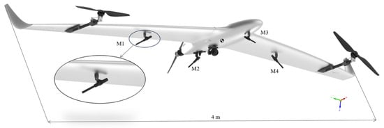
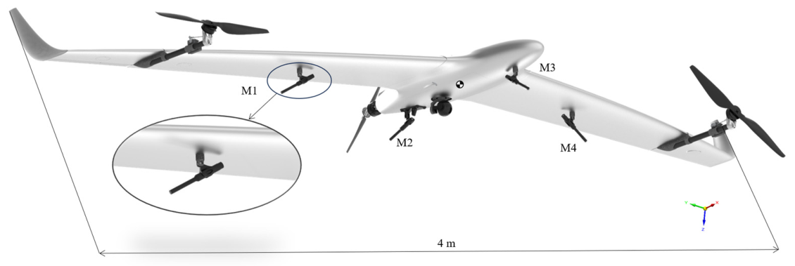
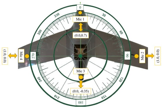
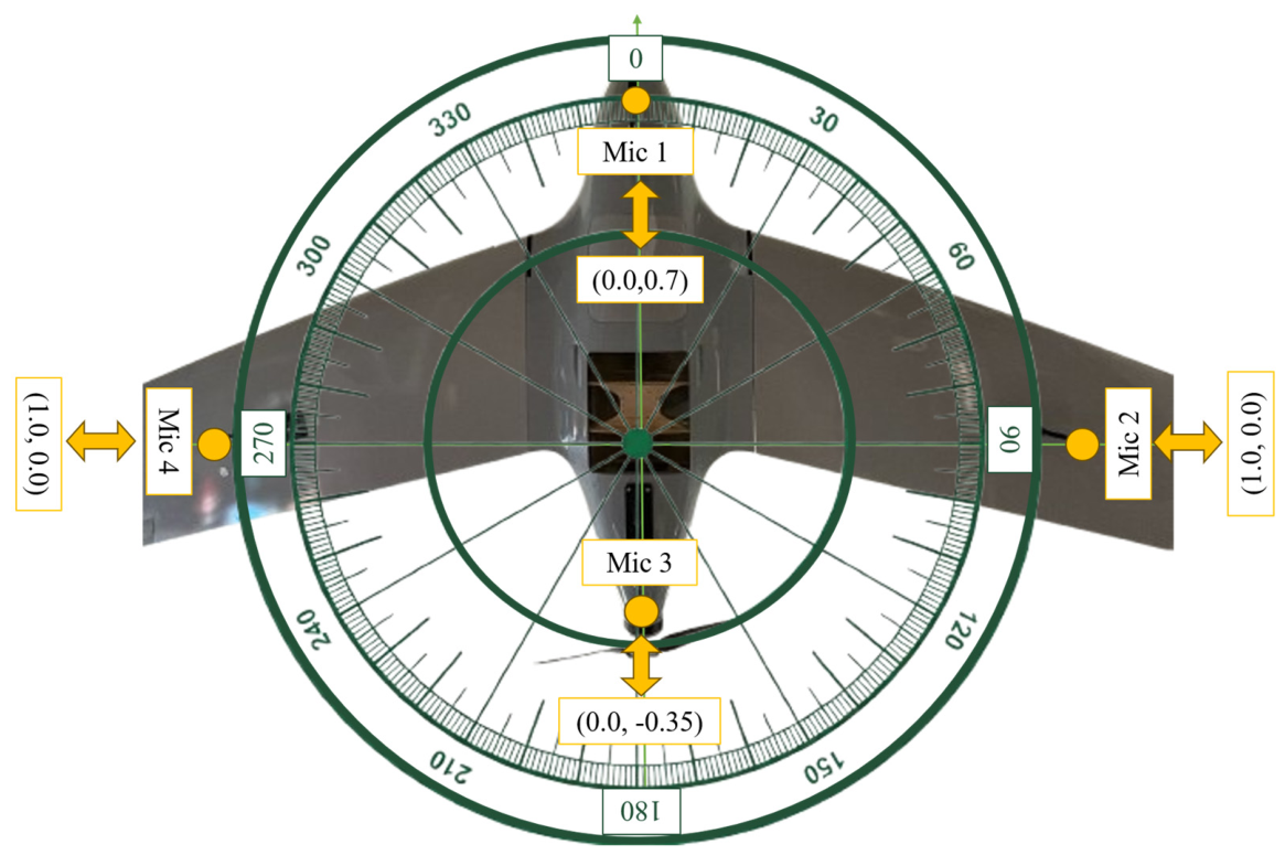
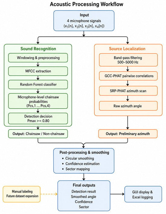
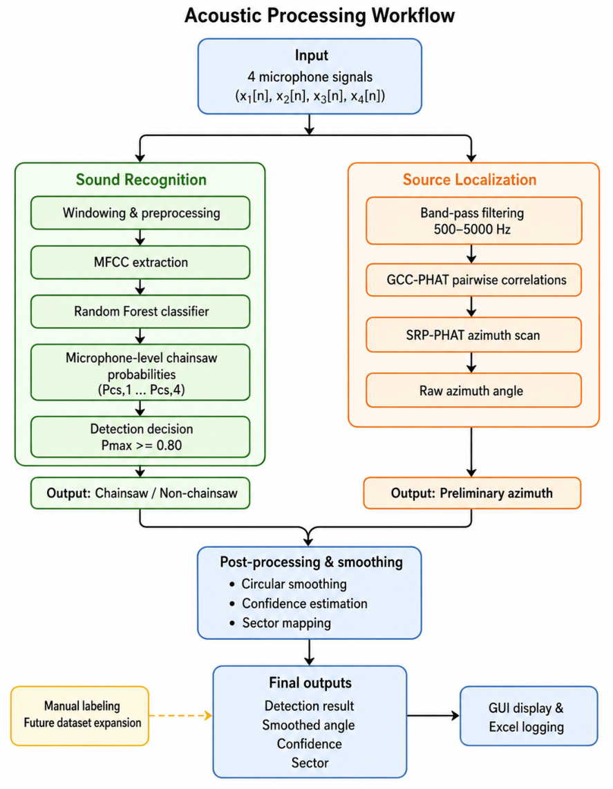
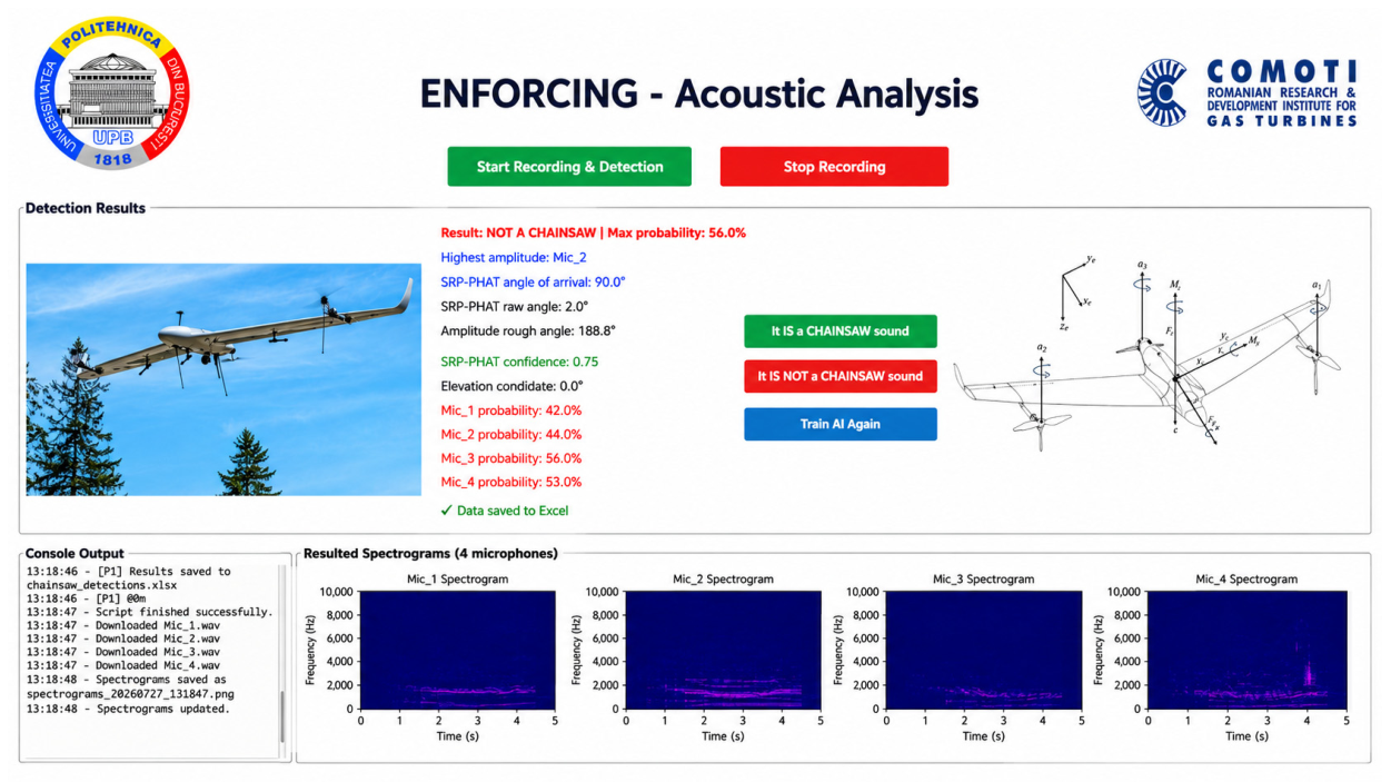
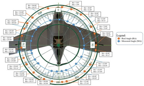
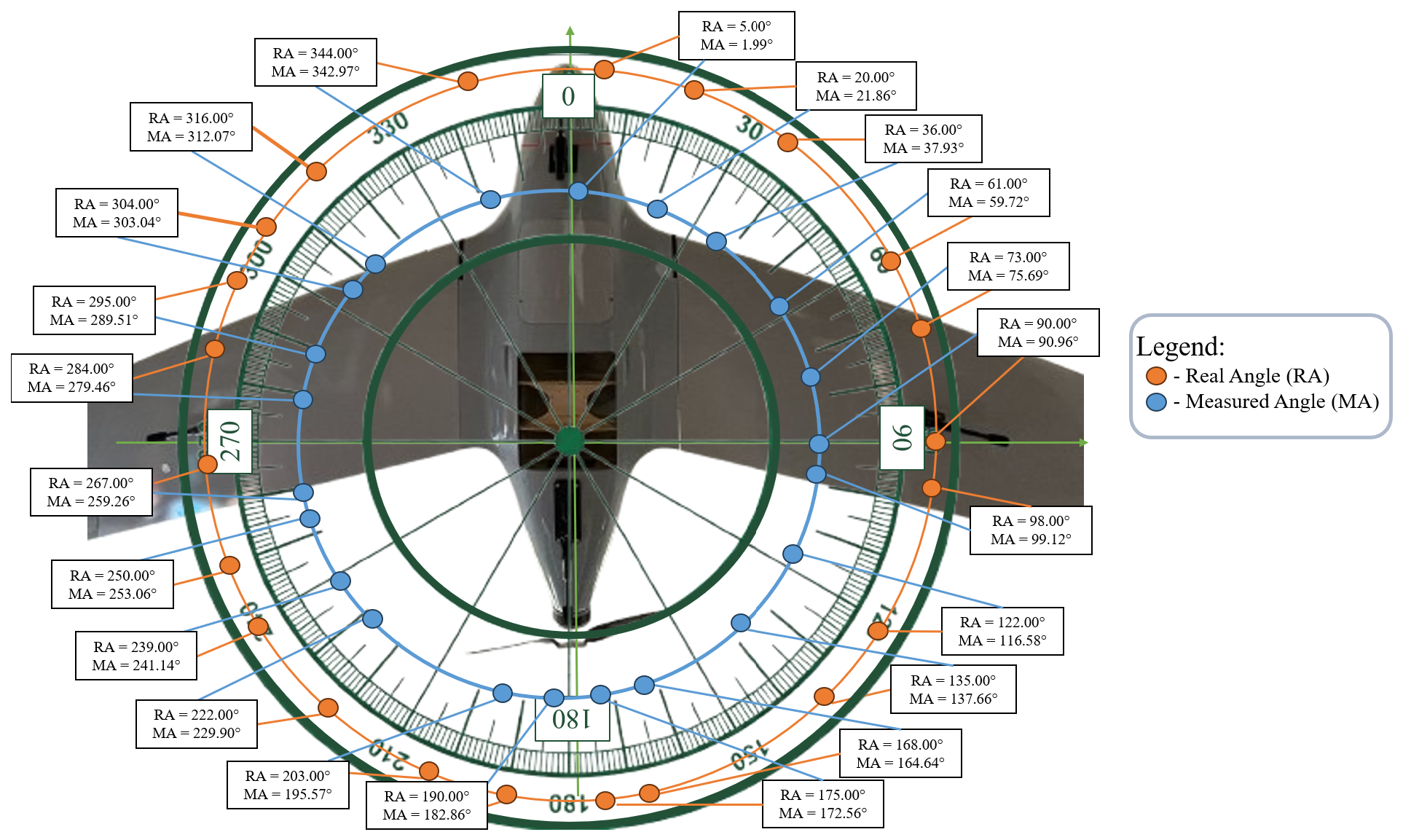
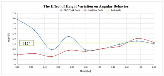
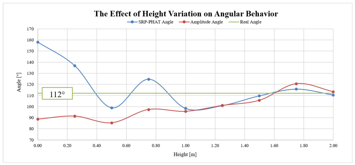

Disclaimer/Publisher’s Note: The statements, opinions and data contained in all publications are solely those of the individual author(s) and contributor(s) and not of MDPI and/or the editor(s). MDPI and/or the editor(s) disclaim responsibility for any injury to people or property resulting from any ideas, methods, instructions or products referred to in the content. |
© 2026 by the authors. Licensee MDPI, Basel, Switzerland. This article is an open access article distributed under the terms and conditions of the Creative Commons Attribution (CC BY) license.