


Abstract
Parametric array loudspeakers (PALs) generate highly directional sound through the nonlinear demodulation of ultrasonic carriers, making them suitable for localized audio delivery. However, their long-range propagation and their interactions with environmental obstacles have not been thoroughly investigated. This study measured the distance attenuation of PAL-generated sound at distances of up to 40 m and the reflection characteristics of planar and cylindrical obstacles, and compared the results with those of a conventional loudspeaker. The distance attenuation of the PAL differed substantially from that of a conventional loudspeaker. Across the approximately 0.7 to 7 kHz frequency range, which includes key speech components, PAL-generated sound attenuated less over distance. Planar surfaces produced highly directional specular reflections of PAL-generated sound, whereas cylindrical obstacles produced quasi-omnidirectional scattering. Simulations that used a quasilinear Westervelt model and a hybrid finite-difference time-domain method attributed the reduced attenuation to the extended virtual-source region, whose length depends on atmospheric absorption of the ultrasonic carrier. They attributed the reflection characteristics to reflection of the carrier by the obstacles. The simulations also indicated that ground reflections may have contributed to the attenuation measured over long distances. These findings provide acoustic considerations for deploying PALs in public announcement systems, accessibility applications, and targeted audio installations.
1. Introduction
Parametric array loudspeakers (PALs), also known as ultrasonic parametric speakers or audio spotlight systems, offer a unique method of sound reproduction by harnessing nonlinear acoustic effects to generate highly directional audible sounds [1,2]. Unlike conventional electrodynamic loudspeakers, which directly radiate audible frequencies, PALs transmit amplitude-modulated ultrasonic carrier waves that undergo self-demodulation through cumulative nonlinear interactions as they propagate through air [3,4]. The resulting audible sound retains the narrow beam characteristics of the original ultrasonic carrier. This process enables PALs to achieve angular spreads of audible sound that are typically an order of magnitude narrower than those of equivalent conventional sources [5,6].
The exceptional acoustic properties of PALs have led to their adoption in a diverse array of applications. In museums and exhibition spaces, PALs facilitate the delivery of spatially localized audio content, allowing visitors to receive exhibit-specific information without cross-talk or interference from adjacent installations [7,8,9,10]. In artistic and theatrical environments, the technology enables the creation of immersive and dynamic audio experiences, supporting innovative spatial sound effects [11]. Commercially, PALs are employed in advertising and digital signage to deliver promotional audio to specific zones within retail environments, while minimizing acoustic pollution in surrounding areas [12].
Additionally, the precise directivity of PALs has been leveraged in active noise control applications. By generating focused anti-noise signals, PALs can establish localized quiet zones [13,14,15]. This targeted approach contrasts with conventional noise control systems, which typically influence the entire sound field, and enables individualized noise management. Furthermore, PALs facilitate directional audio guidance by projecting signals along targeted paths, thereby assisting users—particularly individuals with visual impairments—while minimizing interference in crowded environments, such as transit hubs and public spaces [16,17,18].
Extensive research has elucidated the fundamental acoustic behavior of PALs under controlled laboratory conditions. Berktay’s far-field solution [2], along with subsequent refinements [19,20], provides expressions for the demodulated sound pressure as a function of carrier frequency, modulation parameters, and propagation distance. Ju and Kim [21] investigated the near field experimentally and showed that the attenuation of PAL-generated sound there does not follow the inverse-square law. The transition between the near- and far-field regions, which influenced beam formation, was analyzed by Zhong et al. [22]. Concurrently, advancements in signal processing have yielded techniques to mitigate harmonic distortion: preprocessing techniques based on square root and integration operations address the nonlinear demodulation process [23,24], whereas adaptive compensation is achieved through advanced approaches, such as Volterra filters [25]. Comparative studies of modulation schemes—including single-sideband [26,27] and modified amplitude modulation (MAM)—have further clarified their respective distortion characteristics [28].
Despite these advances, significant gaps persist in our understanding of PAL behavior under real-world deployment conditions. Most existing acoustic characterizations are limited to short distances (typically under 10 m) and controlled environments. However, practical applications, such as public announcement systems, outdoor setups, and pedestrian guidance, require effective sound projection over tens of meters, where reflections, obstacles, and ambient noise are prevalent. The attenuation characteristics of PALs at extended ranges are not well documented, particularly with respect to frequency-dependent behavior within speech-relevant bands (0.3–7 kHz). Although models predict the generation of audible sound through parametric interaction, empirical data on long-range performance in complex acoustic environments remain scarce.
Similarly, the reflection characteristics of the PAL-generated sounds from environmental obstacles remain insufficiently explored. Zhong et al. conducted field studies on planar surfaces, revealing that reflection patterns are dependent on both angle and frequency [29]. However, real-world environments feature a diverse array of obstacle geometries, such as poles and pillars, which are prevalent in urban and indoor settings. Understanding the interaction between the PAL-generated sound and these obstacles is essential for accurately predicting acoustic behavior and optimizing system placement.
To address these knowledge gaps, this study undertakes a systematic experimental investigation of the PAL propagation and reflection characteristics under conditions representative of practical deployment. The specific objectives are as follows:
- 1.
- To characterize the distance attenuation of PAL-generated sound across the audible frequency range at distances up to 40 m, and to compare these results with those obtained from conventional loudspeakers under equivalent conditions.
- 2.
- To investigate the reflection characteristics from both planar and cylindrical obstacles, quantifying the directional distribution of reflected sound as a function of incident angle and frequency.
- 3.
- To synthesize the experimental findings into actionable guidelines for the deployment of PAL systems in applications that require directional sound delivery over extended distances.
Measurements were conducted in both anechoic chambers and outdoor environments to distinguish intrinsic acoustic properties from environmental influences, while also evaluating system performance under realistic conditions. By directly comparing PAL and conventional loudspeaker behavior under identical scenarios, this study provides a clear assessment of the unique propagation characteristics that set parametric array systems apart.
The following sections detail the related work (Section 2), experimental methods and results for distance attenuation (Section 3), reflection characteristics (Section 4), and numerical simulations of these characteristics (Section 5), followed by a discussion of practical implications (Section 6), and concluding remarks with recommendations for future research (Section 7).
2. Related Work
Research on PALs has significantly evolved since Westervelt’s seminal work on parametric acoustic arrays in 1963 [1]. The literature can be broadly categorized into three interconnected domains: fundamental acoustic properties, signal processing methodologies, and practical applications.
2.1. Acoustic Characteristics and Propagation Behavior
The theoretical basis of PALs lies in the nonlinear interaction of ultrasonic carrier waves in air, which generates highly directional audible sounds through self-demodulation [2,3]. Berktay’s far-field solution established the core relationship between the modulated ultrasonic signal and resulting audible waveform, enabling subsequent advances in preprocessing techniques for distortion reduction [2]. The unique narrow-beam characteristics of the PALs, resulting from the short wavelength of the ultrasonic carrier, have been further elucidated through experimental studies by Yoneyama et al. [5] and Kamakura and Sakai [16], who demonstrated the feasibility of generating highly localized sound fields.
Several comprehensive reviews have synthesized decades of research on PAL acoustics. Gan et al. [20] provided an extensive overview of the parametric array technology in air, whereas Shi et al. [19] focused on directivity-control strategies. In terms of propagation characteristics, Ju and Kim [21] reported that, in the near field, the directivity and attenuation of PAL-generated sound deviate from far-field approximations and that the attenuation does not follow the inverse-square law. Zhong et al. [22] analysed the transition from near-field to far-field regions, establishing critical distance thresholds essential for practical deployment. Their work also highlighted the unique reflection characteristics of PAL-generated sound, demonstrating that reflection behavior from planar surfaces is highly dependent on both the incident angle and frequency content [29]. Zhong and Qiu [30] recently presented a comprehensive analysis of sound fields generated by PALs, covering reflection, transmission, scattering, and propagation in rooms. Zhong et al. [31] further demonstrated that a rigid sphere placed in the beam reflects ultrasound, which generates audible sound in front of the sphere. As a result, a listener in front of the PAL perceives the sound as though the sphere reflected it.
2.2. Signal Processing and Modulation Techniques
The inherent nonlinearity of PAL sound generation results in significant harmonic distortion, prompting extensive research into compensation techniques. Amplitude modulation techniques have evolved from basic double-sideband modulation to more advanced methods, including single-sideband modulation [26,27] and MAM [23]. San Martín et al. [28] conducted systematic experimental comparisons of distortion characteristics across various modulation schemes, providing valuable insights for practical implementation.
Advancements in digital signal processing implementations have facilitated real-time distortion compensation through preprocessing algorithms. Tan et al. [24] developed preprocessing techniques for distortion reduction, whereas Ji et al. [25] introduced Volterra filter-based approaches for nonlinear distortion mitigation. Furthermore, hardware implementations on field-programmable gate array platforms, as reported by Karnapi et al. [32] and Wu et al. [33], have enabled precise beam steering and multi-channel processing capabilities.
2.3. Applications in Public Spaces and Accessibility
The high directivity of PALs has driven a wide array of practical applications in which localized sound delivery is advantageous. In exhibition and museum settings, PALs facilitate audio annotation for individual exhibits, minimizing interference between adjacent displays [7,8]. Kondo et al. [10] found that floor reflections significantly reduced the intelligibility of speech from ceiling-mounted PALs. Intelligibility improved when the PALs were oriented so that reflections traveled outside the listening area. In commercial environments, such as retail and advertising, their ability to deliver targeted audio messages to specific spatial zones is increasingly leveraged [11,20].
Active noise control is another significant application domain, with PALs enabling the creation of localized quiet zones through directional anti-noise generation [13,14]. Tanaka et al. [15] demonstrated binaural noise control using parametric arrays, achieving personal noise reduction without impacting nearby listeners. More recently, Zhu et al. [34] introduced a nonlinear sound field control framework for multi-channel PAL arrays to reduce undesired audible sound caused by indoor scattering and reflections.
Applications that support visually impaired individuals have been explored since the early 2000s. Kamakura and Sakai applied PALs to audible pedestrian signals and reported that the signals were more localizable on a crosswalk than those from a conventional loudspeaker and that visually impaired pedestrians deviated less from the crosswalk [16]. Omori et al. [17] proposed hybrid systems that combine parametric and conventional loudspeakers to enhance guidance efficiency. In a recent study, Mashiba et al. [18] used a pair of PALs to present stereophonic earcons that guided visually impaired people through a shopping mall. They found that users identified the direction to a target facility more quickly than with a tactile map.
2.4. Limitations of Existing Studies and Research Objectives
Despite substantial progress in the understanding of PAL acoustics and the development of diverse applications, significant knowledge gaps persist regarding their propagation behavior in real-world deployment scenarios. Most existing research has characterized acoustic properties under controlled laboratory conditions, leaving uncertainties regarding performance in practical environments where factors, such as distance-dependent attenuation, reflections from environmental surfaces, and varying ambient noise levels, can differ significantly from idealized measurements.
In particular, the distance attenuation characteristics of PALs over extended ranges (beyond 10 m) remain insufficiently documented, particularly within the frequency bands most critical for speech communication (0.3–7 kHz). Furthermore, although previous studies have examined reflections from planar surfaces and scattering from a rigid sphere [29,31], the interaction of PAL-generated sound with common environmental obstacles, including planar surfaces and cylindrical objects such as poles, has not been systematically investigated. Addressing these knowledge gaps is essential for informing practical deployment strategies in real-world environments.
This study conducted comprehensive measurements of the PAL distance attenuation characteristics in both anechoic and outdoor environments and systematically characterized the reflection behavior from flat and cylindrical surfaces. These findings provide essential acoustic data for optimizing PAL deployment in public announcement systems, accessibility solutions, and other applications that require directional sound delivery over extended distances.
2.5. Literature Survey and Use of Generative AI Tools
A preliminary literature survey for this study was assisted by large language models (Claude Opus 5.5 (Anthropic) and ChatGPT GPT-6 (OpenAI)). All references were subsequently verified against their original publications, and any that could not be verified were removed. Grammarly 1.209.0.0 and DeepL 26.11.13023090762 assisted with language editing. The authors conducted the study design, data collection, analysis, and interpretation entirely themselves.
3. Distance Attenuation Characteristics of PAL-Generated Sound
The distance decay characteristics of the radiated sound were measured and analysed at both near and far field positions in an anechoic chamber and in outdoor environments.
3.1. Measurement Method
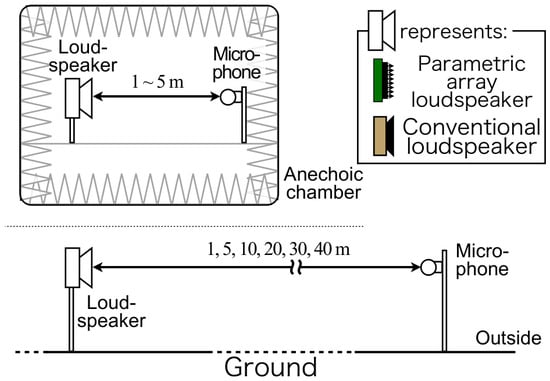
An overview of the measurement environment is shown in Figure 1.
Figure 1.
Experimental setup for measuring the attenuation characteristics of conventional and parametric array loudspeakers.
The measurements were conducted in an anechoic chamber and in outdoor environments (background noise level of 49 dB) to validate the acoustic characteristics of the radiated sound at near and far field positions.
Outdoor measurements were conducted on a paved concrete surface in an open area, with no significant reflective structures within 50 m of the measurement axis. Measurements took place on 11 February 2013 between approximately 16:00 and 17:00. Data from the nearest Japan Meteorological Agency weather station, in Tsukuba, Ibaraki Prefecture, show that the air temperature was 6.5 °C, the relative humidity was 27%, and the wind speed was 4.2 m/s from the north-northwest during this period. Since these values came from the weather station and not from measurements at the site, they are reported as reference values. To reduce wind noise, recordings were made when wind at the site appeared minimal.
The microphone was positioned 1.0 m above the ground. Although the paved surface produced ground reflections at this height, the 1/1-octave band analysis described below smoothed the resulting comb-filtering effects.
Measurements were conducted using an omnidirectional microphone (Kenwood MGR-E8) with a flat frequency response across the audible range (20 Hz–20 kHz) and were positioned directly in front of the speaker.
For these experiments, we used either a standard full-range speaker (BOSE 101MM) or a PAL (HSS Japan HSS-3000; carrier frequency: 40 kHz; external dimensions: 162 mm × 317 mm; effective radiating aperture: approximately 140 mm × 300 mm).
The loudspeaker was positioned at a height of 1.0 m for measurements in both the anechoic chamber and outdoors.
The distance between the speaker and microphone was set from 1 to 5 m, at intervals of 1 m in the anechoic chamber and at 5, 10, 20, 30, and 40 m for outdoor measurements.
The measurement signal was synthesized as an M-sequence signal using MATLAB R2023b (MathWorks) with a sampling frequency of 96.0 kHz and a signal length of 10 s. The signal was converted to analog through an audio interface (Roland UA-1010), amplified using a power amplifier (included with HSS-3000), and reproduced through the speaker at a level that achieved a signal-to-noise ratio of 15–20 dB at a distance of 1.0 m. The received signal was recorded by the omnidirectional microphone through the same audio interface (24-bit converter) and stored as WAV files at a sampling frequency of 96.0 kHz with 16-bit resolution.
To assess attenuation characteristics, we obtained the impulse response at each distance through circular cross-correlation of the recorded signal with the M-sequence. We then calculated the frequency response using a fast Fourier transform (FFT). The resulting spectra were then processed using a 1/1-octave band-pass filter. Subsequently, the relative gain change, referenced to the 1-m measurement, was calculated for each measurement environment and speaker type, thereby deriving the distance-dependent attenuation characteristics.
The 1/1-octave band analysis was selected to reflect standard practices in audio system design and to provide a comprehensive overview of the frequency-dependent behavior across the audible spectrum. This bandwidth also enables sufficient statistical averaging, effectively mitigating the impact of measurement noise in outdoor conditions.
3.2. Results
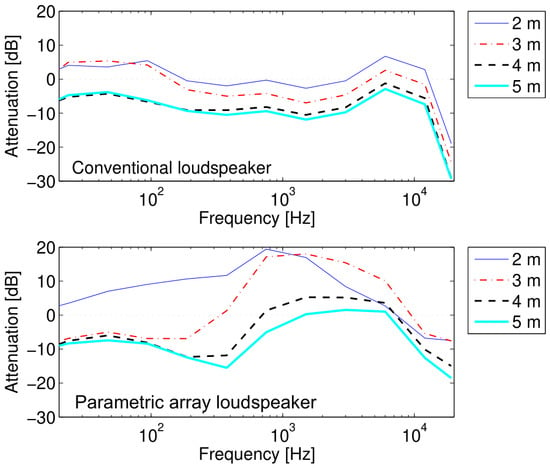
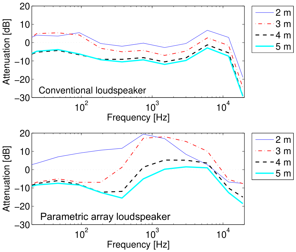
The attenuation characteristics of the radiated sound at a distance of 5 m or less are shown in Figure 2. A comparison of the measured characteristics with the level change expected from spherical spreading (a 6 dB decrease per doubling of distance) is presented in Section 5 (Figure 7). For conventional speakers, a general decrease in sound level was observed across most frequency bands as distance increased. However, in the bands below 0.2 kHz and between 3 and 12 kHz, a gain increase of up to approximately 5 dB was detected at 2–3 m compared with the results at the 1 m measurement point. Beyond 4 m, the gain was lower than that at the 1 m point in all frequency bands. The most pronounced attenuation occurred in the 0.2–3 kHz range at all distances, except for frequencies above approximately 12 kHz.
Figure 2.
Distance attenuation characteristics measured in anechoic chamber (1–5 m range). (Top): Conventional loudspeaker (BOSE 101MM). (Bottom): PAL (HSS-3000). Reference level: sound pressure at a distance of 1 m. Positive values represent a gain increase relative to the reference.
In contrast, the PAL displayed frequency bands with higher gain than at the 1 m position at distances up to 5 m. Specifically, at 2 m, a maximum gain of approximately 20 dB was observed below approximately 7 kHz. At 3 m, the maximum gain was approximately 18 dB between 0.4 and 9 kHz. At 4 m, the maximum gain was approximately 5 dB between approximately 0.7 and 7 kHz. At 5 m, the gain was approximately 2 dB between approximately 1.2 and 6.5 kHz. In PALs, the gain change with distance differs for each frequency band [16], and the present results are consistent with these findings.
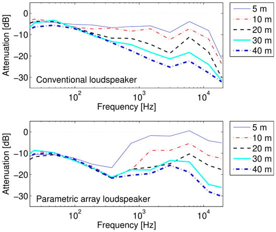
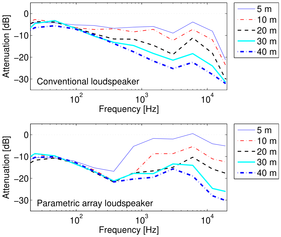
The attenuation characteristics of the radiated sound at distances of up to 40 m are shown in Figure 3. For conventional speakers, attenuation with distance generally increases as the frequency increases. In contrast, the PAL’s attenuation beyond 5 m remained relatively constant below approximately 0.3 kHz, but varied at higher frequencies. Even at approximately 0.3 kHz, the PAL showed substantially greater attenuation relative to the 1-m reference, approximately 10–20 dB, than the conventional loudspeaker, which showed approximately 5 dB. Conversely, in the frequency range of approximately 0.7 to 7 kHz, the PAL demonstrated less attenuation with distance than the conventional speaker. Notably, within the 0.7 to 3 kHz band, attenuation between 20 and 40 m remained within 3 dB for the PAL, compared with 3 to 7.3 dB for the conventional speaker. As examined in Section 5, these level changes at long distances may also reflect the influence of ground reflections; the remainder of this paper therefore focuses on the qualitative difference in distance attenuation between the two loudspeakers.
Figure 3.
Attenuation characteristics of the conventional loudspeaker and PAL measured outdoors (5–40 m). The frequency characteristics of each loudspeaker measured at a distance of 1 m were used as the reference.
3.3. Discussion
The results in Section 3.2 indicate that the distance attenuation characteristics of PALs differ significantly from those of conventional speakers. Specifically, the PAL demonstrated reduced attenuation with distance in the frequency range of approximately 0.7–7 kHz, which contains key components of human speech. Sound level is one of the primary cues for auditory distance perception, and visual loss systematically affects the ability to judge the distance of sound sources [35,36]. While the highly directional nature of PALs may facilitate the perception of sound source direction, the reduced distance attenuation may make it harder for listeners to judge distance from changes in sound level. Depending on their placement, this may also affect visually impaired individuals’ ability to determine their position, although the present study did not test this possibility perceptually. If confirmed, this effect may be reduced by approaches that bring the distance attenuation of PALs closer to that of conventional speakers. Ikefuji et al. improved low-frequency sound quality by modifying the amplitude modulation method of PALs [37], and such advances may reduce the disparities between PALs and conventional speakers. An alternative approach is to combine PALs with conventional speakers, as proposed by Omori et al. [17] and Geng et al. [38].
The gain increase observed at distances of 2–5 m for the PAL can be attributed to the cumulative effect of the parametric demodulation process. As reported by Zhong et al. [22], the demodulated sound pressure accumulates within the near-field region until it reaches the transition distance, beyond which the far-field spreading losses its dominance. The observed increase in the gain at intermediate distances aligns with this theoretical framework, in which the effective source region extends along the propagation axis.
These distance characteristics can be interpreted with the virtual-source model of the parametric array [1,2,30]. In this model, virtual sources distributed along the ultrasonic beam generate audible sound. The extent of the virtual-source region depends on two length scales. The first is the Rayleigh distance of the ultrasonic beam, , where S is the radiating area and is the ultrasonic wavelength. For the HSS-3000 (carrier frequency 40 kHz; effective aperture approximately 140 mm × 300 mm), is approximately 5 m. This range corresponds to the build-up of audible sound along the beam. Although this mechanism qualitatively explains the gain increase observed at 2–5 m, the simulation did not reproduce its magnitude (Section 5). Possible reasons are discussed in Section 6.4.
The second length scale is determined by atmospheric absorption of the ultrasonic carrier. The strength of the virtual sources is proportional to the product of the primary wave amplitudes and therefore decays approximately as , where is the absorption coefficient at the carrier frequency (in Np/m) and z is the distance along the beam. Under the outdoor measurement conditions (6.5 °C and 27% relative humidity), the absorption coefficient at 40 kHz, calculated according to ISO 9613-1 [39], is approximately 0.43 dB/m. Thus, the virtual-source strength has a characteristic decay length of approximately 10 m, given by . At 20 °C and 50% relative humidity, the coefficient rises to approximately 1.3 dB/m, and the characteristic length falls to approximately 3.3 m. A longer virtual-source region delays the transition to the far field and maintains a high level of PAL-generated sound relative to the near field. The simulation in Section 5 indicates that this effect contributes approximately 9–12 dB at 20 m across the 0.5 to 4 kHz range, which explains the substantially lower attenuation of the PAL than of the conventional loudspeaker. However, free-field propagation alone does not explain the level change between 20 and 40 m; Section 5 examines this further. For the conventional loudspeaker, the observed increase in attenuation with frequency outdoors is consistent with atmospheric absorption of audible sound. Under the measurement conditions, this absorption amounts to approximately 0.4 dB at 1 kHz, 3.4 dB at 4 kHz, and 6.1 dB at 8 kHz over a 40-m path.
4. Reflection Characteristics of PAL-Generated Sound
The reflection characteristics of the radiated sound were measured using an anechoic chamber.
For these measurements, both flat plates and cylindrical objects were utilized as reflective surfaces.
4.1. Measurement Method
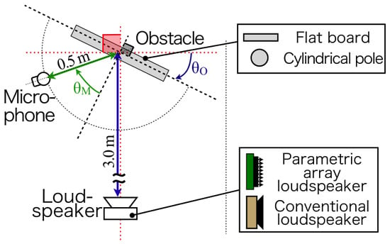
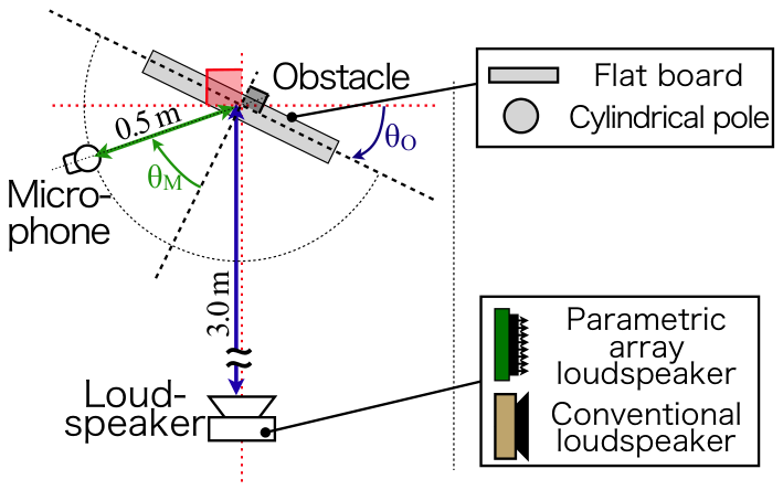
The measurements were conducted in an anechoic chamber, with the setup shown in Figure 4.
Figure 4.
Experimental setup for measuring the sound of a loudspeaker reflected by an obstacle.
In addition to the speaker and microphone, reflective objects were introduced to assess their impact on the radiated sound. Two types of objects were used: a flat plate and a cylinder.
The flat plate was a lumber board measuring 60 cm × 60 cm, with a thickness of 10 mm. The cylinder was a commercially available, smooth-surfaced round wooden post with a diameter of 15 cm.
The cylinder diameter was selected to approximate that of signposts and traffic signal poles commonly found on streets in Japan. In terms of wavelength, for the cylinder (k: wavenumber; a: radius) ranges from approximately 0.7 at 0.5 kHz to 11 at 8 kHz. This range spans the transition from the diffraction-dominated regime to the geometrical reflection regime within the speech frequency band. For the PAL’s 40-kHz ultrasonic carrier, . The width of the flat plate exceeds the wavelength above approximately 0.6 kHz. The width-to-wavelength ratio is approximately 1.7 at 1 kHz and 70 at 40 kHz. Thus, specular reflection is expected to dominate over most of the speech frequency band and for the ultrasonic carrier. The speaker was placed on a stand 1.0 m high. The flat plate was positioned so that its center aligned with the center of the speaker. The cylinder was mounted on a stand so that its vertical center was approximately level with the speaker center. The floor of the anechoic chamber consisted of a rigid grating. Floor reflections were small enough to neglect. The distance between the speaker and the object was 3.0 m. The microphone was placed on a circular arc with a radius of 0.5 m, centered on the object and at the same height as the speaker (1.0 m).
For the flat plate, the angle between the speaker and plate was set at .
The angle between the plate and microphone was set at 0– in increments of .
When installing the cylinder, was employed, and was set as in the case of the flat plate.
To eliminate the effect of direct sounds from the speaker on the microphone, similar measurements were performed in the absence of the object.
The equipment, including speakers, microphones, and audio interfaces, as well as the procedures for generating measurement signals and recording, were consistent with those described in Section 3.1.
The reflection characteristics of each object were evaluated based on the directional properties of the reflected sound. For each recorded signal obtained under different measurement conditions (speaker/object type, , ), the frequency response was determined from the impulse response obtained as described in Section 3.1.
The resulting spectra were processed with a 1/1 octave band filter to determine the gain in each frequency band. Gains measured in the absence of any object were also calculated, enabling the determination of gain differences attributable to the presence of the reflective objects. Subsequently, for each measurement condition, the relative gain difference was calculated relative to the case in which for the corresponding frequency band. This relative gain difference was then used to characterize the directional properties of the reflected sound.
4.2. Results
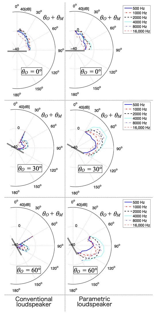
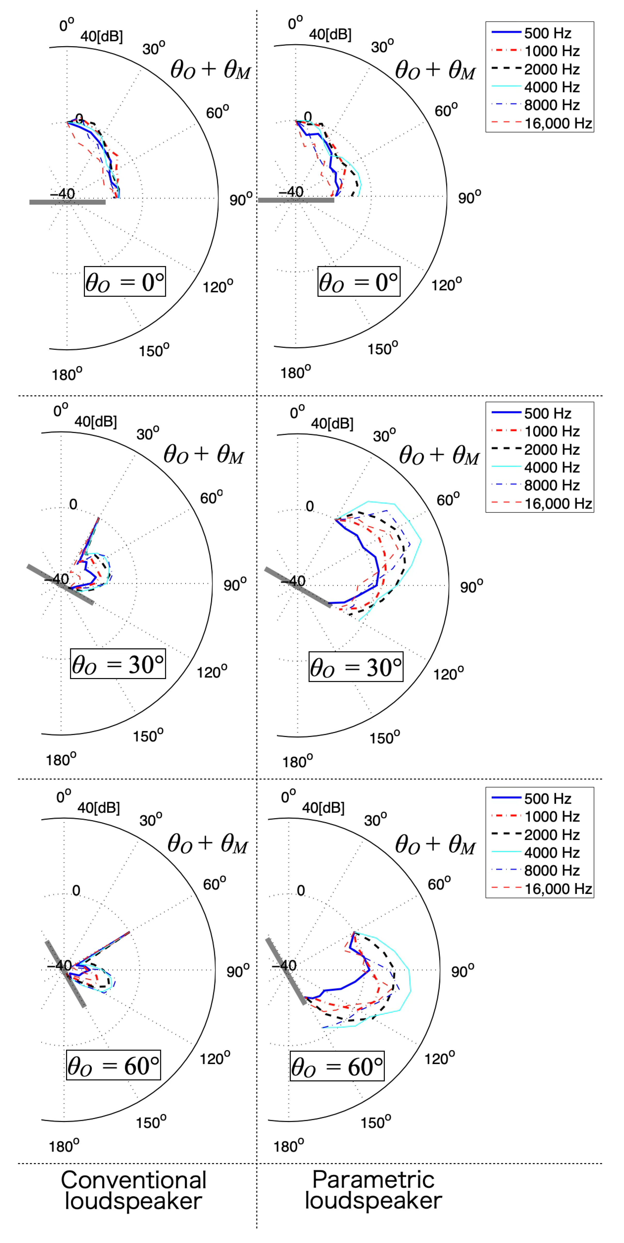
The directional characteristics of the sound reflected from a flat plate are shown in Figure 5. First, when the radiated sound was directed perpendicularly toward the plate (), minimal differences were observed in the directional characteristics of the reflected sound between the conventional speaker and PAL, regardless of frequency band. However, when the sound was emitted at an oblique angle to the side of the flat plate (), the conventional speaker demonstrated high directivity. Specifically, the reflected sound gain was maximized in the direction normal to the plate (), and the reflected angle closely matched the incident angle relative to the plate. In particular, the directivity characteristics became sharper as the angle of incidence relative to that of the flat plate increased, a trend that was consistent across all frequency bands.
Figure 5.
Directional characteristics of reflected sound from a flat plate.
In contrast, the PAL displayed a different pattern: the reflected sound gain was highest when the incident and reflection angles were aligned relative to the flat plate. The sharpening of directivity with increasing incident angle was also observed for the PAL. However, the variation in the directional characteristics across frequency bands was more pronounced when using this sound source. In particular, the gain of the reflected sound in the direction normal to the plate was not significantly elevated when using the PAL.
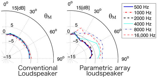
The directional characteristics of sound reflected from the cylinder are shown in Figure 6. Notably, the conventional speaker displayed an almost omnidirectional response, with variations within 2 dB across all frequency bands. In contrast, the PAL demonstrated a directivity difference between and within 5 dB. Notably, below 2 kHz, the gain decreased at lateral angles compared with that of the front, whereas above 4 kHz, the gain increased at these angles.
Figure 6.
Directional characteristics of the sound reflected from a cylindrical pole.
4.3. Discussion
As shown in Figure 5 and Figure 6, the sound emitted by PALs is more significantly affected by reflective surfaces than that from conventional speakers. Specifically, when sound was incident on a flat surface, the reflected sound demonstrated high directivity and gain in the direction corresponding to the reflection angle, which closely matched the incident angle. These findings indicate that, when deploying PALs to guide individuals with visual impairments, factors such as the angles of the surrounding flat surfaces must be considered in their placement. Furthermore, Kurimoto et al. used multiple reflectors to realize stereo effects with a PAL [40], which illustrates that reflecting surfaces can be used deliberately to shape the sound field. Similarly, Morise et al. used PALs to reproduce three-dimensional sound fields [9]. Kondo et al. improved the intelligibility of PAL guide audio by orienting the PALs so that floor reflections remained outside the listening area [10]. This underscores the importance of sound field control when utilizing PALs to facilitate smooth navigation for visually impaired individuals.
Furthermore, when PALs are used with traffic signals that have audio devices, cylindrical objects such as utility poles are often nearby. Sound from the PAL may reflect off these surfaces in a quasi-omnidirectional manner, which could confuse visually impaired individuals. This possibility requires verification through perceptual experiments. Potential countermeasures include directing the PAL beam away from these objects and applying sound-absorbing materials to their surfaces.
These differences can be explained by considering the reflection of the ultrasonic carrier in addition to that of the audible sound. Zhong et al. [29] showed that the audible sound reflected from a surface consists of two components: the reflection of the audible sound generated before reaching the surface, and the audible sound newly generated by the reflected ultrasound, the latter of which determines the directivity of the reflected sound. For the flat plate, whose width corresponds to approximately 70 wavelengths at 40 kHz, the ultrasonic beam is reflected specularly, and the reflected ultrasound continues to generate a directional audible beam along the specular direction. This is consistent with the high directivity observed at the specular angle for the PAL. For the cylinder, at 40 kHz, which places the ultrasonic reflection in the geometrical regime. Because the local angle of incidence varies across the convex surface, the incident ultrasonic beam is reflected into a wide angular fan, and the audible sound generated by the reflected ultrasound is correspondingly distributed over a wide range of directions. An analogous effect has been reported for a rigid sphere [31]. In the audible range, by contrast, for the cylinder ranges from approximately 0.7 to 5.5 between 0.5 and 4 kHz, so that diffraction of the audible sound around the cylinder becomes increasingly important toward lower frequencies. The frequency dependence of the lateral gain observed for the PAL (a decrease below 2 kHz and an increase above 4 kHz) may reflect the differing relative contributions of these two mechanisms; the hybrid FDTD simulation in Section 5.2, which includes both mechanisms, reproduced the increase in the lateral gain above 4 kHz, whereas the decrease below 2 kHz was not reproduced.
5. Numerical Simulation
To examine the physical mechanisms that underlie the measured characteristics and determine how well established models reproduce them, numerical simulations were conducted for distance attenuation and the reflection experiment. Studies have reported full nonlinear finite-difference time-domain (FDTD) simulations of sound generated by parametric arrays [41,42]. However, these simulations require a grid spacing of approximately one-tenth of the ultrasonic wavelength, or about 0.9 mm at 40 kHz. A simulation of propagation over 40 m would therefore require on the order of grid points, even in an axisymmetric two-dimensional domain, and would be computationally prohibitive. This limitation has also been noted in direct time-domain calculations of PAL-generated sound [22]. Accordingly, distance attenuation was analyzed with a quasilinear Westervelt model (Section 5.1), whereas the reflection experiment, which has a much smaller domain, was reproduced with a hybrid FDTD method (Section 5.2).
5.1. Distance Attenuation: Quasilinear Westervelt Model
5.1.1. Method
The audible sound produced by the PAL was calculated using the quasilinear solution of the Westervelt equation [1,30]. The two primary waves at ( kHz; : audio frequency) were modeled as axisymmetric Gaussian beams under the paraxial approximation. Their equivalent radius was m, selected so that the Rayleigh distance equaled for the effective aperture m2. The audible sound was calculated by integrating the virtual sources, which were proportional to the product of the primary pressures, over the beam volume using the free-space Green’s function. Atmospheric absorption, as specified in ISO 9613-1 [39], was applied to both the primary waves and the audible wave. Octave-band levels were calculated by averaging the energy at three frequencies in each band and normalizing the result to the level at 1 m. The conventional loudspeaker was modeled as a point source with atmospheric absorption. The comparison included two atmospheric conditions: the outdoor measurement condition (6.5 °C, 27% relative humidity) and 20 °C with 50% relative humidity. To evaluate the effect of the paved ground, a rigid ground plane was incorporated using the image method, with loudspeaker and microphone heights of 1.0 m. Interaction terms between the direct primary waves and the ground-reflected primary waves were neglected. The authors implemented the simulations in Python 3.11.9 based on the formulations in [1,22,30,39].
5.1.2. Results
Figure 7 shows the simulated on-axis levels in free field. Beyond several meters, the level of the PAL-generated sound relative to 1 m was considerably higher than that of the point source, and this difference depended strongly on the atmospheric condition: at 20 m, the PAL level relative to 1 m was approximately to dB at 6.5 °C and 27% relative humidity, but approximately to dB at 20 °C and 50% relative humidity between 0.5 and 4 kHz, compared with approximately to dB for the point source. Compared with the 6 dB decrease per doubling of distance predicted by spherical spreading (thin line in Figure 7), the PAL level at 20 m was approximately 15–18 dB higher under the measurement condition and approximately 2–9 dB higher at 20 °C and 50% relative humidity. The point source followed the spherical-spreading line, except for additional atmospheric absorption at high frequencies. This is qualitatively consistent with the reduced attenuation of the PAL observed in the 0.7–7 kHz range (Section 3.2) and supports the interpretation in terms of the length of the virtual-source region (Section 3.3). Within 3 m, by contrast, the simulated PAL level stayed within approximately dB of the 1-m level, which is considerably smaller than the gain increase of up to approximately 20 dB measured at 2–3 m in the anechoic chamber (Figure 2); this discrepancy is discussed in Section 6.4.
Figure 7.
Simulated free-field on-axis octave-band levels relative to the level at 1 m. Solid line: PAL at 6.5 °C and 27% relative humidity (outdoor measurement conditions); dashed line: PAL at 20 °C and 50% relative humidity; dotted line: point source; thin line: dB per doubling of distance, as expected from spherical spreading.
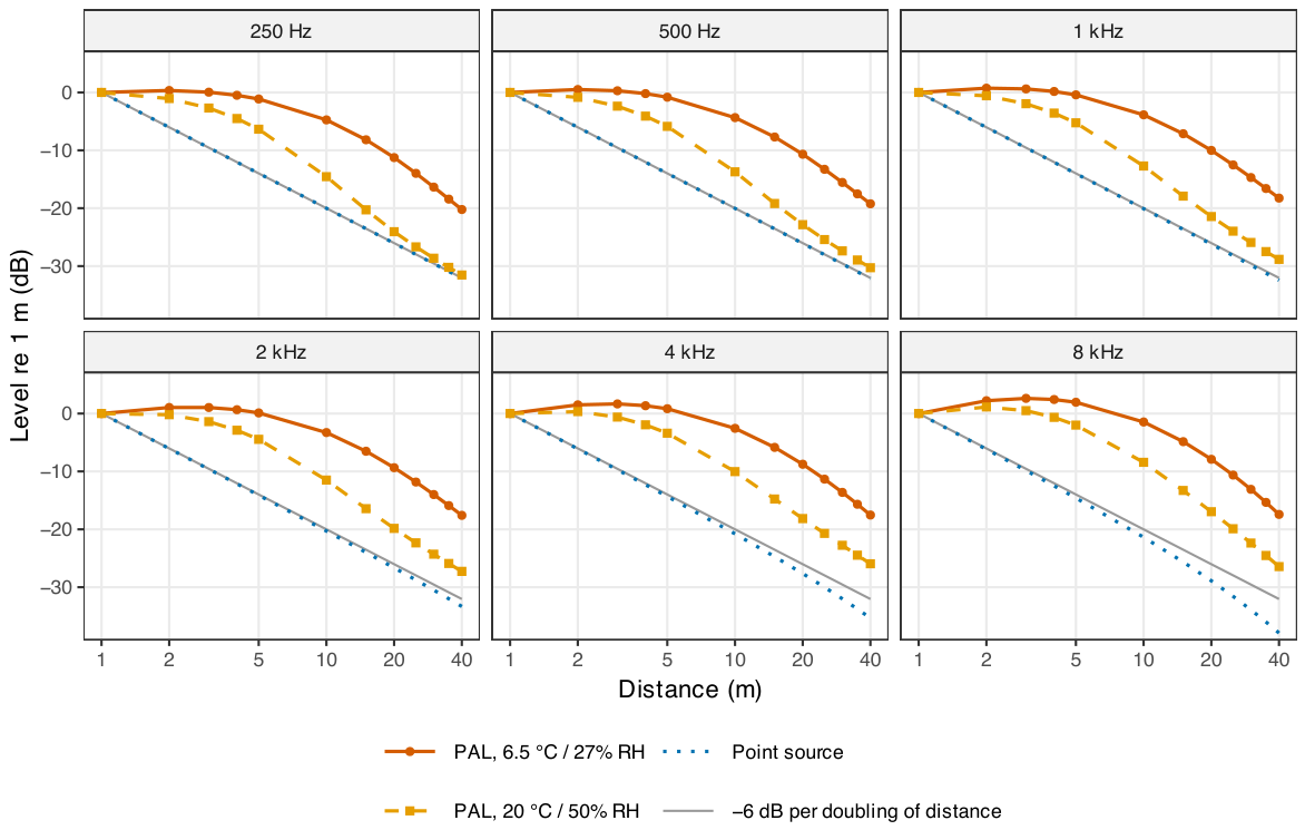
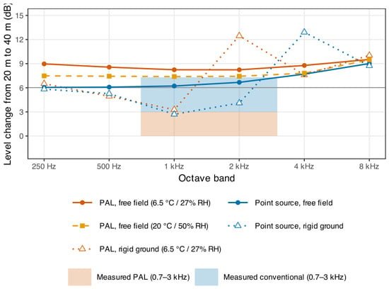
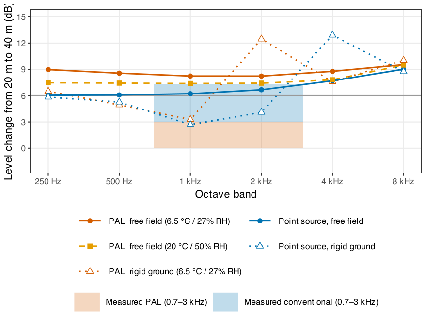
Figure 8 compares the simulated level change between 20 and 40 m with the measured ranges. In free field, the simulated change for the PAL was 8.2 to 9.5 dB. This exceeds the 6 dB expected from spherical spreading because the observation points lie beyond the virtual-source region, and it is clearly greater than the measured change of 3 dB or less. With rigid ground included, the simulated change became strongly frequency dependent for both loudspeakers because of interference between direct sound and ground-reflected sound. For the PAL, the change was 3.3 dB at 1 kHz and 12.5 dB at 2 kHz. For the point source, it was 2.7 to 4.1 dB at 1 to 2 kHz, which is comparable to the measured range of 3 to 7.3 dB. Changing the assumed loudspeaker height from 1.0 to 0.8 m altered these values by up to approximately 5 dB. These results suggest that ground reflections in the measurement geometry, in addition to the PAL’s propagation characteristics, may have contributed to the small level changes measured between 20 and 40 m. The actual ground is neither perfectly rigid nor flat, and wind and turbulence reduce the coherence of reflected sound. Therefore, the rigid-ground simulation is expected to exaggerate the interference pattern.
Figure 8.
Simulated level changes from 20 to 40 m for each octave band, in a free field and over rigid ground, with loudspeaker and microphone heights of 1.0 m. Shaded areas show the measured ranges in the 0.7–3 kHz band.
5.2. Reflection: Hybrid FDTD Simulation
5.2.1. Method
The reflection experiment (Section 4) was reproduced in a two-dimensional horizontal plane with a hybrid method. This method combines a geometrical model of the ultrasonic carrier with a linear FDTD simulation of the audible sound. First, the 40-kHz carrier was modeled as a Gaussian beam based on the PAL’s horizontal aperture (140 mm). Atmospheric absorption followed ISO 9613-1 [39], at 20 °C and 50% relative humidity, as assumed for the anechoic chamber. The obstacle shadowed the incident beam. We modeled reflection from the flat plate with the Gaussian beam of the image source, and modeled reflection from the cylinder with specular ray tracing over its convex surface. Second, we injected virtual sources into a linear FDTD solver for the audible sound. The source amplitudes were proportional to the carrier intensity, defined as the product of the primary pressures in the quasilinear Westervelt formulation [1,30], and their delays corresponded to the carrier travel time. The solver used a staggered-grid (Yee-type) scheme, which has also been used in FDTD analyses of parametric sound generation [41]. We added the virtual sources to the pressure field as additive (soft) sources [43]. Thus, the simulation included both the audible sound generated before the carrier reached the obstacle and the sound generated by the reflected carrier [29].
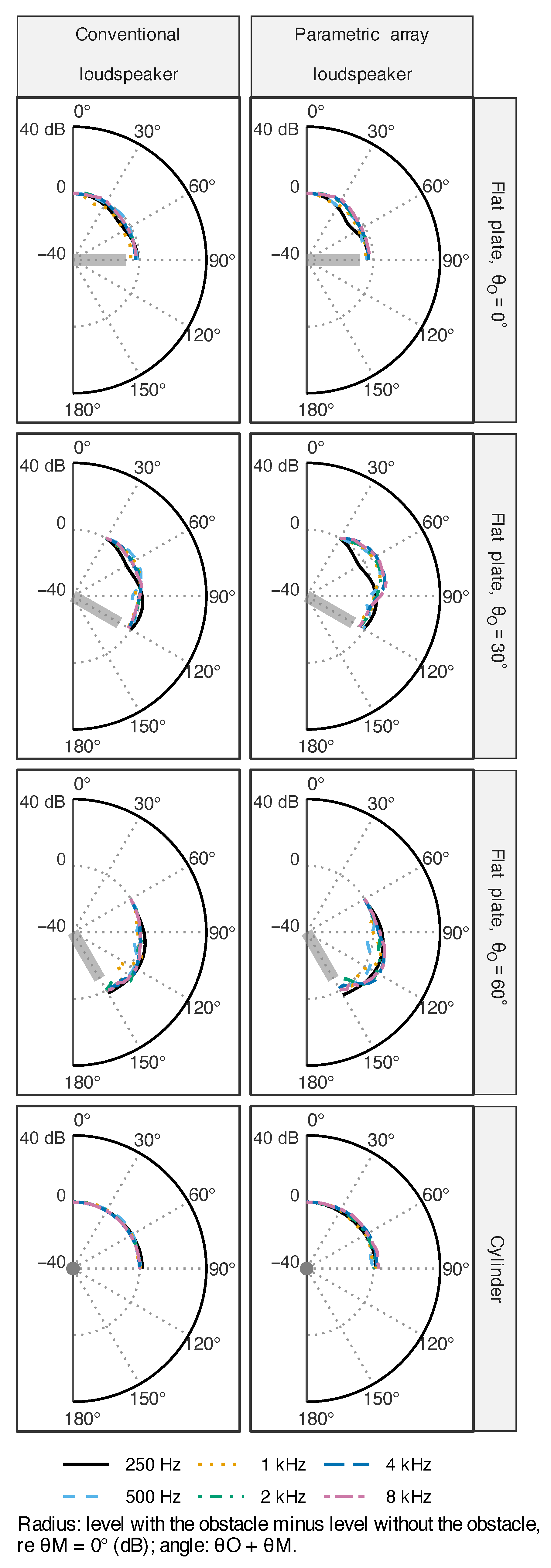
The grid spacing was 4 mm, and the time step was . We modeled the obstacles as rigid and surrounded the computational domain with an absorbing layer. The conventional loudspeaker was modeled as a point source at its position. We used a broadband pulse and analyzed the signals at the measurement positions (radius 0.5 m; –) in octave bands, as in the measurements. We calculated the difference between the octave-band levels with and without the obstacle and normalized it to the value at . We simulated the flat plate at , , and , and the cylinder at . We measured from the normal to the obstacle that faced the loudspeaker. Thus, corresponds to the specular direction for the flat plate. We plotted the results against , in the same format as Figure 5 and Figure 6.
As a solver check, the scattered field for the conventional loudspeaker and the cylinder agreed with the exact two-dimensional series solution for a rigid cylinder [44] within 1 dB up to the 4-kHz band and within 1.8 dB in the 8-kHz band. The larger deviation resulted from numerical dispersion, with approximately 7.6 grid points per wavelength at the upper edge of the 8-kHz band.
5.2.2. Results
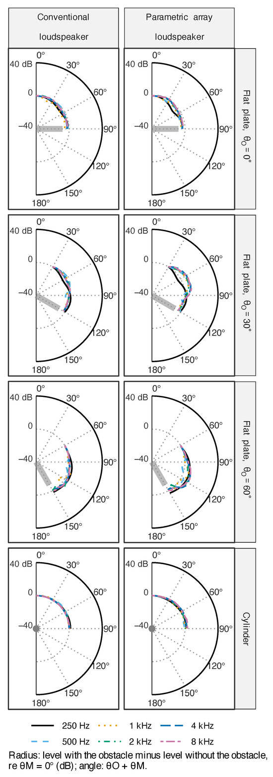
Figure 9 shows the simulated directional characteristics. For the flat plate at , the two loudspeakers had similar patterns, and gain decreased gradually toward by approximately 1–5 dB. This result agrees with the small differences between the loudspeakers in the measurements (Section 4). At and , the PAL showed a pronounced maximum near the specular direction (– and 50–, respectively). In the frequency bands of 0.5 kHz and above, its gain at exceeded the gain in the normal direction by approximately 6–8 dB. At , this difference was approximately 7–10 dB in the bands of 1 kHz and above. By comparison, the conventional loudspeaker showed weaker maxima of approximately 2–5 dB. These results are consistent with the measured finding that the PAL’s reflected sound was strongest when the incident and reflection angles were aligned. For the cylinder, the gain variation of the conventional loudspeaker remained within 1.7 dB in all bands, consistent with the measured nearly omnidirectional response, which remained within 2 dB. The PAL’s variation reached 3.4 dB, and its gain at lateral angles (60–) increased by approximately 2–3.4 dB in the 4- and 8-kHz bands. This result reproduces the measured increase in lateral gain above 4 kHz. However, the simulation did not reproduce the decrease in lateral gain measured below 2 kHz. In the 0.5- and 1-kHz bands, simulated gain varied non-monotonically between approximately and dB. Overall, the simulated variations, which remained within approximately dB, were smaller than those measured. This difference may result from the two-dimensional approximation and the geometrical treatment of the carrier.
Figure 9.
Directional characteristics of the reflected sound simulated using the hybrid FDTD method for the flat plate (, , and ) and the cylinder. The radius represents the difference between the octave-band levels with and without the obstacle, relative to the level at (centre: dB; outer circle: dB). The angle represents . The grey bar and disc represent the flat plate and cylinder, respectively.
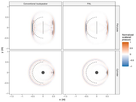
Further analysis of the simulated sound fields explained the difference between the two loudspeakers. For both loudspeakers, the reflected sound, defined as the difference between sound pressures measured with and without the obstacle, followed a similar directional pattern. However, along the measurement arc without the obstacle, the direct sound level varied by less than 1 dB for the conventional loudspeaker, but by up to approximately 12 dB for the PAL in the 4-kHz band. The obstacles therefore had a greater effect on the PAL, primarily because its direct sound was weak outside the beam. Consequently, reflected sound at a comparable level had a greater influence on the sound received at those positions.
Figure 10 shows the scattered sound fields. The FDTD method has long served to visualize reflection, diffraction, and scattering in acoustics [45,46]. For the cylinder, sound scattered from both loudspeakers spreads across the entire front side. For the flat plate, it is concentrated near the specular direction. The hybrid model accounts for both the scattering of audible sound produced before the obstacle and audible sound produced by the reflected carrier. Its agreement with the measurements therefore supports the interpretation in Section 4.3. The remaining discrepancies may arise from the two-dimensional approximation, which assumes that the obstacles are infinitely long in the vertical direction, and from the geometrical treatment of the carrier, which neglects ultrasonic diffraction at the obstacle edges.
Figure 10.
Snapshots of the scattered sound field, defined as the difference between the fields with and without the obstacle, were simulated with the hybrid FDTD method for a broadband pulse at 10.5 ms after emission (). Each panel is normalized by its maximum absolute value. The dashed line marks the measurement arc.
6. General Discussion
Section 3 and Section 4 examined the distance attenuation and reflection characteristics of the sound emitted by PALs, respectively. Here, we provide an integrated analysis of these findings in the context of existing literature.
6.1. Distance Attenuation and Near-to-Far Field Transition
In this study, PAL-generated sound attenuated less with distance than sound from the conventional loudspeaker in the frequency range of approximately 0.7–7 kHz. This low-attenuation characteristic is attributed to the unique sound generation mechanism of PALs. As reported by Zhong et al. [22], the demodulated sound pressure in PALs accumulates in the near-field region, and far-field spherical spreading losses become dominant only beyond the transition distance. Ju and Kim [21] also showed that the attenuation of PAL-generated sound in the near field does not follow the inverse-square law, which is consistent with the presence, although not the magnitude, of the gain increase observed at 2–5 m in this study. According to a comprehensive review by Gan et al. [20], this cumulative demodulation effect is fundamental to the efficiency of PALs in long-distance sound propagation. As shown in Section 5, the virtual-source model, together with ultrasonic absorption under the measurement conditions, explains why the PAL level remains high relative to the near field. Ground reflections in the measurement geometry may also have influenced the change in level between 20 and 40 m.
6.2. Reflection Characteristics and Environmental Obstacles
Regarding reflection characteristics, Zhong et al. [29] demonstrated that planar surfaces display angle- and frequency-dependent reflection patterns from planar surfaces under controlled conditions. Building upon their findings, this study systematically investigates reflections at multiple incident angles and the behavior of cylindrical obstacles. Reflections from planar surfaces generate highly directional reflected sound in the direction in which the reflection angle closely matches the incident angle. Notably, this reflected sound retains the low-attenuation property characteristic of the original beam. Consequently, in real-world environments containing flat surfaces, such as walls, sound may propagate farther in unintended directions compared with conventional loudspeakers. In contrast, cylindrical obstacles with a diameter of 15 cm generated quasi-omnidirectional scattered sound. In urban settings, where utility poles and similar structures are prevalent, this scattered sound can obscure the source direction, complicating sound localization.
6.3. Implications
The acoustic characteristics have significant implications in designing guidance systems for individuals with visual impairments. Previous studies have shown that the directional beam of PALs can assist visually impaired pedestrians in orientation [16,18]. However, sound level is one of the primary cues for auditory distance perception, and visual loss affects the ability to judge the absolute distance of sound sources [35,36]. The low-attenuation properties of PALs may impair this distance perception. Research on accessible pedestrian signals by Wall et al. and Barlow et al. [47,48] has shown that the acoustic characteristics of audible signals strongly affect the ability of blind pedestrians to align and maintain their heading during street crossing, highlighting the importance of addressing this challenge. However, the present study did not assess auditory perception or navigation behavior. The implications discussed in this section are therefore hypotheses based on the acoustic measurements. Their practical relevance requires validation through perceptual and behavioral experiments with visually impaired participants.
Several strategies may help address these potential issues. One promising approach involves hybrid systems that combine PALs with conventional loudspeakers, as suggested by Omori et al. [17] and Sugibayashi et al. [49].
Geng et al. [38] recently combined PAL and electrodynamic loudspeaker arrays to enhance the construction of virtual sound sources. By complementarily providing directional information through the PAL directionality and distance information through conventional loudspeaker attenuation characteristics, more reliable guidance can be anticipated. Another viable solution, demonstrated by Kondo et al. [10] in exhibition environments, is to orient the PALs so that reflections are directed away from the listening area. Third, advancements in signal processing techniques by Ji et al. [25] and Ikefuji et al. [37] are expected to enable PALs to more closely replicate the frequency characteristics to approximate those of conventional loudspeakers more closely. Furthermore, integration with personal sound zone technologies, as developed by Donley et al. [50] and Zhu et al. [34], also holds promise for enabling precise sound field design and minimizing interference between multiple guidance signals.
Conversely, the unique properties of PALs—specifically their high reflectivity and low attenuation—can be actively harnessed to develop innovative assistive methods. For example, the efficient dissemination of disaster alerts in indoor spaces can be achieved by utilizing wall reflections, whereas personal information presentation systems that incorporate binaural noise control, as demonstrated by Tanaka et al. [13,15], represent an additional promising application.
Based on our experimental results and discussion, we propose the following considerations for PAL deployment. These recommendations reflect the specific configurations examined in this study and are qualitative, not general engineering thresholds:
- 1.
- In the frequency range of approximately 0.7–7 kHz, PAL-generated sound attenuates less with distance than sound from a conventional loudspeaker. This attenuation depends on atmospheric absorption of the ultrasonic carrier and on ground reflections. Therefore, it should be verified under the atmospheric conditions and geometry of the intended installation.
- 2.
- Flat reflective surfaces oriented at angles greater than 30° relative to the PAL beam axis generate specular reflections, preserving directivity characteristics similar to the original beam.
- 3.
- Cylindrical obstacles (diameter ≃ 15 cm) produce quasi-omnidirectional scattered sound that may interfere with guidance applications. PAL beams should therefore avoid direct incidence on these obstacles. Quantitative clearance criteria require further investigation with systematic variation of obstacle spacing.
6.4. Limitations
This study had several limitations. First, measurements were conducted using a single PAL model (HSS-3000). Different PAL systems, with varying carrier frequencies and aperture sizes, may demonstrate distinct propagation characteristics. Second, the outdoor measurements were conducted under a single set of winter conditions (6.5 °C and 27% relative humidity). Temperature, humidity, and wind speed were not measured at the site; the values reported in Section 3.1 came from the nearest weather station. As shown in Section 5, absorption of the 40-kHz carrier under these conditions is considerably lower than at 20 °C and 50% relative humidity. Thus, under warmer or more humid conditions, the level of PAL-generated sound at long distances relative to the near field is expected to be lower. Third, the outdoor measurements did not separate ground reflections from the paved surface from the direct sound. The simulation suggests that these reflections may have affected the level change between 20 and 40 m for both loudspeakers. Fourth, the attenuation characteristics were normalized to the level measured at 1 m. At this distance, neither loudspeaker is an ideal point source. For the PAL in particular, audible sound is still generated along the beam, so the level at 1 m does not provide a far-field reference. Moreover, the gain increase of up to approximately 20 dB observed for the PAL at 2–3 m in the anechoic chamber was considerably greater than the increase predicted by the simulation. The 1-m measurement may have been affected by interference, such as reflections between the loudspeaker and microphone assembly, or by the microphone’s response to the intense ultrasonic field near the PAL. Therefore, the near-field gains in Figure 2 should be interpreted with caution. Fifth, this study did not evaluate auditory perception or navigation behavior. The implications for guidance systems therefore require validation through perceptual and behavioral experiments. Future studies should include a broader range of PAL systems and environmental conditions to validate and extend these findings.
7. Conclusions
Our investigation of distance attenuation and reflection characteristics highlights potential challenges in using PALs to guide visually impaired individuals. The results revealed that, in the frequency range of approximately 0.7–7 kHz, PALs demonstrated significantly less attenuation with distance compared with conventional loudspeakers. Furthermore, the variation in reflection characteristics owing to the shape of the reflecting objects was more pronounced for PALs compared with those of conventional speakers. Numerical simulations based on a quasilinear Westervelt model and a hybrid FDTD method attributed these characteristics to the extended virtual-source region of the parametric array, whose length depends on atmospheric absorption, and to reflections of the ultrasonic carrier by obstacles. The simulations also suggested that ground reflections may have contributed to the attenuation measured at long distances. These findings indicate that reflected sound, which undergoes less attenuation over distance, warrants careful consideration when PALs guide visually impaired individuals in real-world environments. The effects of these acoustic characteristics on navigation performance require validation through perceptual and behavioral experiments.
In the future, we plan to investigate the perceptual characteristics of sounds emitted by PALs and to develop enhanced guidance methods for visually impaired users. Additionally, we aim to explore advanced simulation techniques for sound fields utilized in navigation support.
Author Contributions
Conceptualization, T.M. and M.U.; methodology, T.M. and M.U.; validation, T.M.; formal analysis, T.M.; investigation, T.M. and M.U.; resources, T.M. and M.U.; data curation, T.M.; writing—original draft preparation, T.M.; writing—review and editing, M.U.; visualization, T.M.; project administration, T.M. and M.U.; funding acquisition, T.M. All authors have read and agreed to the published version of the manuscript.
Funding
This study was partially supported by JSPS KAKENHI Grant Numbers JP24K21471 and JP26K03355, and JST FOREST Grant Number JPMJFR234Y.
Institutional Review Board Statement
Not applicable.
Informed Consent Statement
Not applicable.
Data Availability Statement
The data in this article and the simulation code are available from the corresponding author upon reasonable request.
Acknowledgments
We would also like to express our sincere gratitude to Hiroyoshi Takahashi of the National Institute of Advanced Industrial Science and Technology (AIST) and Shinichi Sakamoto of the Institute of Industrial Science, The University of Tokyo. During the preparation of this manuscript, the authors used Claude Opus 5.5 (Anthropic), ChatGPT GPT-6 (OpenAI), Grammarly 1.209.0.0, and DeepL 26.11.13023090762 for the purposes described in Section 2.5. The authors have reviewed and edited the output and assume full responsibility for the content of this publication.
Conflicts of Interest
The authors declare no conflicts of interest.
References
- Westervelt, P.J. Parametric acoustic array. J. Acoust. Soc. Am. 1963, 35, 535–537. [Google Scholar] [CrossRef] [Scilit]
- Berktay, H. Possible exploitation of non-linear acoustics in underwater transmitting applications. J. Sound Vib. 1965, 2, 435–461. [Google Scholar] [CrossRef] [Scilit]
- Bennett, M.; Blackstock, D. Parametric array in air. J. Acoust. Soc. Am. 1975, 57, 562–568. [Google Scholar] [CrossRef] [Scilit]
- Hamilton, M.F.; Blackstock, D.T. (Eds.) Nonlinear Acoustics; Academic Press: San Diego, CA, USA, 1998. [Google Scholar]
- Yoneyama, M.; Fujimoto, J.; Kawamo, Y.; Sasabe, S. The audio spotlight: An application of nonlinear interaction of sound waves to a new type of loudspeaker design. J. Acoust. Soc. Am. 1983, 73, 1532–1536. [Google Scholar] [CrossRef] [Scilit]
- Pompei, F. Sound from Ultrasound: The Parametric Array as an Audible Sound Source. Ph.D. Thesis, MIT, Cambridge, MA, USA, 2002. [Google Scholar]
- Kurakata, K.; Sato, H.; Seki, Y.; Itoh, N.; Mizunami, T.; Sato, T. Guiding open-house visitors using acoustic signals—An experiment at AIST Open-Lab 2010–. J. Hum. Life Eng. 2011, 12, 57–64. (In Japanese) [Google Scholar] [CrossRef] [PubMed]
- Ando, H.; Watanabe, J. Design Issues of Experience-based Exhibition named “Sensory Circuit Collection”. Trans. Virtual Real. Soc. Jpn. 2010, 15, 471–474. (In Japanese) [Google Scholar] [CrossRef] [PubMed]
- Morise, M.; Sugibayashi, Y.; Kurimoto, S.; Nishiura, T. Acoustic Planetarium: Three-dimensional sound field reproduction system with parametric loudspeakers. Trans. Virtual Real. Soc. Jpn. 2011, 16, 687–693. (In Japanese) [Google Scholar] [CrossRef] [PubMed]
- Kondo, K.; Terada, T.; Kano, F. Speech intelligibility of guide audio with parametric loudspeakers. Noise Control Eng. J. 2012, 60, 548–558. [Google Scholar] [CrossRef] [Scilit]
- Watanabe, J.; Yoshida, T.; Ando, H.; Tavata, T.; Adriana, V.M. Practical Approach of Vibro-scape Design in Multi-media Performing Art. Trans. Virtual Real. Soc. Jpn. 2007, 12, 413–416. (In Japanese) [Google Scholar] [CrossRef] [PubMed]
- Shi, C.; Gan, W.S. Development of parametric loudspeaker. IEEE Potentials 2010, 29, 20–24. [Google Scholar] [CrossRef] [Scilit]
- Tanaka, N.; Tanaka, M. Active noise control using a steerable parametric array loudspeaker. J. Acoust. Soc. Am. 2010, 127, 3526–3537. [Google Scholar] [CrossRef] [Scilit] [PubMed]
- Komatsuzaki, T.; Iwata, Y. Active noise control using high-directional parametric loudspeaker. J. Environ. Eng. 2011, 6, 140–149. [Google Scholar] [CrossRef] [Scilit]
- Tanaka, K.; Shi, C.; Kajikawa, Y. Binaural active noise control using parametric array loudspeakers. Appl. Acoust. 2017, 116, 170–176. [Google Scholar] [CrossRef] [Scilit]
- Kamakura, T.; Sakai, S. Practical development of a parametric loudspeaker. J. Acoust. Soc. Jpn. 2006, 62, 791–797. (In Japanese) [Google Scholar] [CrossRef] [PubMed]
- Omori, K.; Kitayama, I.; Kamakura, T.; Sakai, S. Guiding property of audible traffic signals using parametric speakers and sub-speakers. IEICE Trans. Fundam. Electron. Commun. Comput. Sci. (Japanese Ed.) 2008, J91-A, 1174–1180. (In Japanese). Available online: https://search.ieice.org/bin/summary.php?id=j91-a_12_1174 (accessed on 8 November 2026).
- Mashiba, Y.; Iwaoka, R.; Bilal Salih, H.E.; Kawamoto, M.; Wakatsuki, N.; Mizutani, K.; Zempo, K. Spot-presentation of stereophonic earcons to assist navigation for the visually impaired. Multimodal Technol. Interact. 2020, 4, 42. [Google Scholar] [CrossRef] [Scilit]
- Shi, C.; Kajikawa, Y.; Gan, W.S. An overview of directivity control methods of the parametric array loudspeaker. APSIPA Trans. Signal Inf. Process. 2014, 3, 1–12. [Google Scholar] [CrossRef] [Scilit]
- Gan, W.; Yang, J.; Kamakura, T. A review of parametric acoustic array in air. Appl. Acoust. 2012, 73, 1211–1219. [Google Scholar] [CrossRef] [Scilit]
- Ju, H.S.; Kim, Y.H. Near-field characteristics of the parametric loudspeaker using ultrasonic transducers. Appl. Acoust. 2010, 71, 793–800. [Google Scholar] [CrossRef] [Scilit]
- Zhong, J.; Kirby, R.; Qiu, X. The near field, Westervelt far field, and inverse-law far field of the audio sound generated by parametric array loudspeakers. J. Acoust. Soc. Am. 2021, 149, 1524–1535. [Google Scholar] [CrossRef] [Scilit] [PubMed]
- Kite, T.D.; Post, J.T.; Hamilton, M.F. Parametric array in air: Distortion reduction by preprocessing. In Proceedings of the 16th International Congress on Acoustics (ICA), Seattle, WA, USA, 20–26 June 1998; pp. 1091–1092. [Google Scholar]
- Tan, E.L.; Gan, W.S.; Yang, J. Preprocessing techniques for parametric loudspeakers. In Proceedings of the 2008 International Conference on Audio, Language and Image Processing (ICALIP), Shanghai, China, 7–9 July 2008. [Google Scholar] [CrossRef] [Scilit]
- Ji, W.; Gan, W.S. Identification of a parametric loudspeaker system using an adaptive Volterra filter. Appl. Acoust. 2012, 73, 1251–1262. [Google Scholar] [CrossRef] [Scilit]
- Sakai, S.; Kamakura, T.; Nomura, H.; Yoshida, S. Dynamic SSB modulator for parametric loudspeaker. IEICE Trans. Fundam. Electron. Commun. Comput. Sci. (Japanese Ed.) 2008, J91-A, 1166–1173. (In Japanese). Available online: https://search.ieice.org/bin/summary.php?id=j91-a_12_1166 (accessed on 8 November 2026).
- Ji, P.; Gan, W.S.; Tan, E.L.; Yang, J. Performance analysis on recursive single-sideband amplitude modulation for parametric loudspeakers. In Proceedings of the IEEE 2010 IEEE International Conference on Multimedia and Expo (ICME), Singapore, 19–23 July 2010. [Google Scholar] [CrossRef] [Scilit]
- San Martín, R.; Tello, P.; Valencia, A.; Marzo, A. Experimental evaluation of distortion in amplitude modulation techniques for parametric loudspeakers. Appl. Sci. 2020, 10, 2070. [Google Scholar] [CrossRef] [Scilit]
- Zhong, J.; Wang, S.; Kirby, R.; Qiu, X. Reflection of audio sounds generated by a parametric array loudspeaker. J. Acoust. Soc. Am. 2020, 148, 2327–2336. [Google Scholar] [CrossRef] [Scilit] [PubMed]
- Zhong, J.; Qiu, X. Acoustic Waves Generated by Parametric Array Loudspeakers; CRC Press: Boca Raton, FL, USA, 2024. [Google Scholar] [CrossRef] [Scilit]
- Zhong, J.; Kirby, R.; Karimi, M.; Zou, H.; Qiu, X. Scattering by a rigid sphere of audio sound generated by a parametric array loudspeaker. J. Acoust. Soc. Am. 2022, 151, 1615–1626. [Google Scholar] [CrossRef] [Scilit] [PubMed]
- Karnapi, F.A.; Gan, W.S.; Chong, Y.K. FPGA implementation of parametric loudspeaker system. Microprocess. Microsyst. 2004, 28, 261–272. [Google Scholar] [CrossRef]
- Wu, S.; Wu, M.; Huang, C.; Yang, J. FPGA-based implementation of steerable parametric loudspeaker using fractional delay filter. Appl. Acoust. 2012, 73, 1271–1281. [Google Scholar] [CrossRef] [Scilit]
- Zhu, Y.; Qin, L.; Ma, W.; Fan, F.; Wu, M.; Kuang, Z.; Yang, J. A nonlinear sound field control method for a multi-channel parametric array loudspeaker array. J. Acoust. Soc. Am. 2025, 157, 962–975. [Google Scholar] [CrossRef] [Scilit] [PubMed]
- Nakamura-Funaba, H.; Ueda, M.; Iwamiya, S. Questionnaire survey of the use of sound to support the mobility of the visually impaired. J. Acoust. Soc. Jpn. 2006, 62, 839–847. (In Japanese) [Google Scholar] [CrossRef] [PubMed]
- Kolarik, A.J.; Moore, B.C.J.; Zahorik, P.; Cirstea, S.; Pardhan, S. Auditory distance perception in humans: A review of cues, development, neuronal bases, and effects of sensory loss. Atten. Percept. Psychophys. 2016, 78, 373–395. [Google Scholar] [CrossRef] [Scilit] [PubMed]
- Ikefuji, D.; Nakayama, M.; Nishiura, T. Formulation of Demodulation Criterion Based on Spectral Envelope for Parametric Loudspeaker. IEICE Trans. Inf. Syst. (Japanese Ed.) 2013, J96-D, 655–663. (In Japanese) [Google Scholar]
- Geng, Y.; Hirose, A.; Iwagami, M.; Nakayama, M.; Nishiura, T. Enhanced virtual sound source construction based on wave field synthesis using crossfade processing with electro-dynamic and parametric loudspeaker arrays. Appl. Sci. 2024, 14, 11911. [Google Scholar] [CrossRef] [Scilit]
- ISO 9613-1:1993; Acoustics—Attenuation of Sound During Propagation Outdoors—Part 1: Calculation of the Absorption of Sound by the Atmosphere. ISO: Geneva, Switzerland, 1993.
- Kurimoto, S.; Sugibayashi, Y.; Morise, M.; Nishiura, T. The realization of stereo effects with parametric loudspeaker and multiple reflectors. In Proceedings of the INTER-NOISE 2011, Osaka, Japan, 4–7 September 2011; pp. 4260–4264. [Google Scholar]
- Nomura, H.; Hedberg, C.M.; Kamakura, T. Numerical simulation of parametric sound generation and its application to length-limited sound beam. Appl. Acoust. 2012, 73, 1231–1238. [Google Scholar] [CrossRef] [Scilit]
- Zhu, L.; Florencio, D. 3D numerical modeling of parametric speaker using finite-difference time-domain. In Proceedings of the 2015 IEEE International Conference on Acoustics, Speech and Signal Processing (ICASSP), South Brisbane, QLD, Australia, 19–24 April 2015; pp. 5982–5986. [Google Scholar] [CrossRef] [Scilit]
- Sheaffer, J.; van Walstijn, M.; Fazenda, B. Physical and numerical constraints in source modeling for finite difference simulation of room acoustics. J. Acoust. Soc. Am. 2014, 135, 251–261. [Google Scholar] [CrossRef] [Scilit] [PubMed]
- Morse, P.M.; Ingard, K.U. Theoretical Acoustics; Princeton University Press: Princeton, NJ, USA, 1986. [Google Scholar]
- Sakamoto, S.; Seimiya, T.; Tachibana, H. Visualization of sound reflection and diffraction using finite difference time domain method. Acoust. Sci. Technol. 2002, 23, 34–39. [Google Scholar] [CrossRef] [Scilit]
- Yokota, T.; Sakamoto, S.; Tachibana, H. Visualization of sound propagation and scattering in rooms. Acoust. Sci. Technol. 2002, 23, 40–46. [Google Scholar] [CrossRef] [Scilit]
- Wall, R.S.; Ashmead, D.H.; Bentzen, B.L.; Barlow, J. Directional guidance from audible pedestrian signals for street crossing. Ergonomics 2004, 47, 1318–1338. [Google Scholar] [CrossRef] [Scilit] [PubMed]
- Barlow, J.M.; Scott, A.C.; Bentzen, B.L. Audible beaconing with accessible pedestrian signals. AER J. Res. Pract. Vis. Impair. Blind. 2010, 2, 149–158. [Google Scholar] [PubMed Central]
- Sugibayashi, Y.; Kurimoto, S.; Ikefuji, D.; Morise, M.; Nishiura, T. Three-dimensional acoustic sound field reproduction based on hybrid combination of multiple parametric loudspeakers and electrodynamic subwoofer. Appl. Acoust. 2012, 73, 1282–1288. [Google Scholar] [CrossRef] [Scilit]
- Donley, J.; Ritz, C.; Kleijn, W.B. Reproducing personal sound zones using a hybrid synthesis of dynamic and parametric loudspeakers. In Proceedings of the 2016 Asia-Pacific Signal and Information Processing Association Annual Summit and Conference (APSIPA), Jeju, Republic of Korea, 13–16 December 2016; pp. 1–5. [Google Scholar] [CrossRef] [Scilit]
Disclaimer/Publisher’s Note: The statements, opinions and data contained in all publications are solely those of the individual author(s) and contributor(s) and not of MDPI and/or the editor(s). MDPI and/or the editor(s) disclaim responsibility for any injury to people or property resulting from any ideas, methods, instructions or products referred to in the content. |
© 2026 by the authors. Licensee MDPI, Basel, Switzerland. This article is an open access article distributed under the terms and conditions of the Creative Commons Attribution (CC BY) license.