


Abstract
The methodology described in Eurocode 8, Part 4, for calculating seismic effects on vertical cylindrical rigid and fixed steel storage tanks is programmed in MATLAB®. The walls of the tanks are constructed of shell courses with varying thicknesses of sheet material. The strength conditions for the ultimate limit states of plasticity, elastic buckling, and elastoplastic buckling (“elephant foot”) are checked at many calculation points along the height of the storage tank. The thicknesses of the courses are determined to satisfy all strength conditions for different slenderness ratios of the tanks and for different volume capacities. Tanks with supported roofs and those with self-supporting roofs are considered, as well as open-top tanks. A mass per unit volume capacity is the criterion for optimization for different seismic loadings and steel grades. The criterion is not a smooth function because of the discrete thicknesses of the shell courses and their number. A smooth objective function is created for better parametric optimization analysis. The dependence of the optimal slenderness ratio on the volume capacity is determined, as well as the inverse dependence. The problem of the optimal number of storage tanks in a set of tanks with a given total volume capacity is also considered.
1. Introduction
Storage tanks for liquids such as water, fuel, oil, chemicals, etc., are popular facilities that are part of industrial enterprises. These facilities are vulnerable to earthquakes [1,2,3,4,5,6], which makes seismic loading a major design load, especially in highly seismic areas. The design of storage tanks is complicated not only by the probabilistic nature of the seismic loading but also by the interaction between the fluid and the structure, which has not been sufficiently studied and modeled. The numerical modeling of the fluid–structure interaction requires large computational resources [7,8,9,10] and is not yet completely reliable. Simple and reliable analytical or numerical methods are sought for use in the storage tank design [11,12,13].
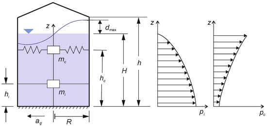
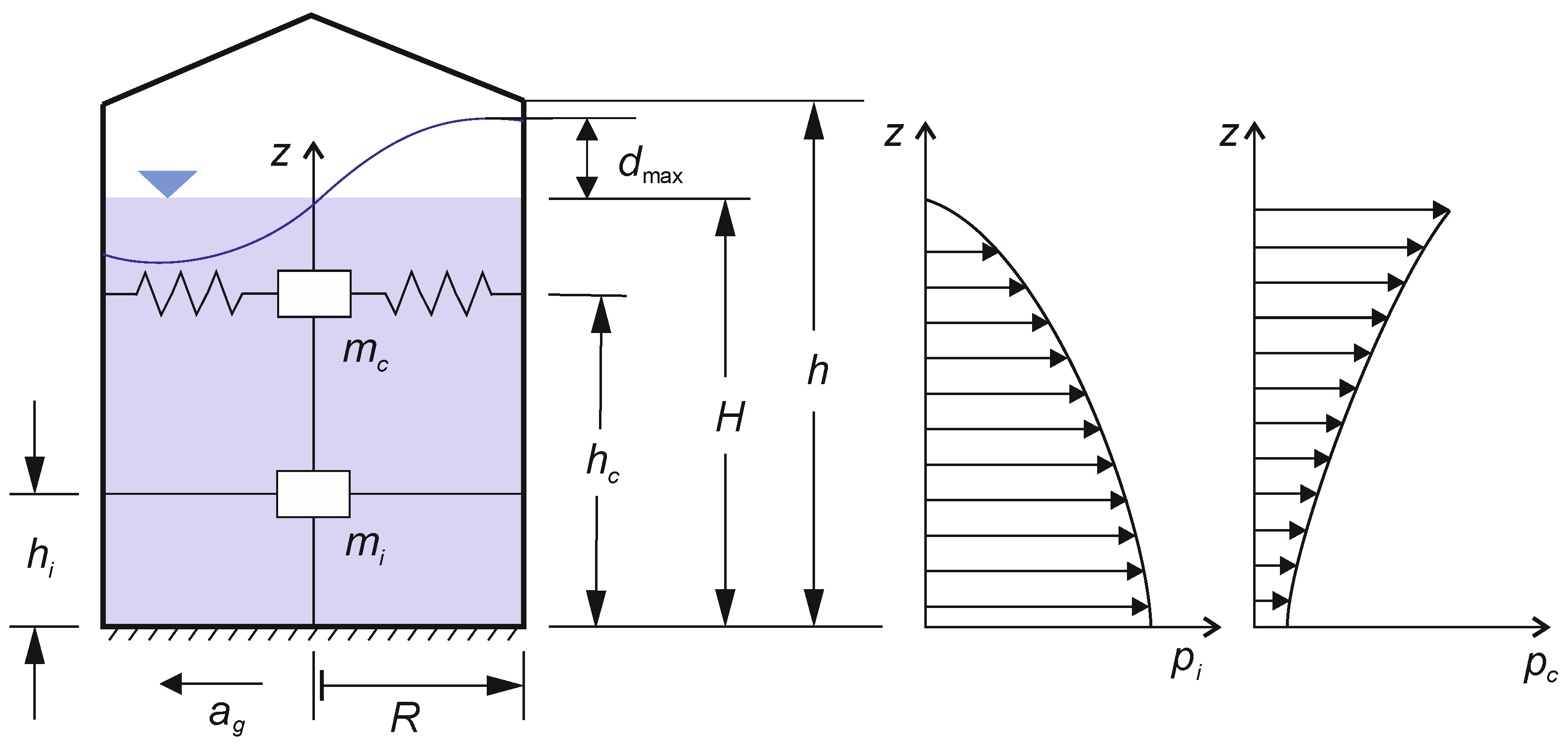
The simplest analytical method considers the static action of the inertial forces from the seismic motion of the Earth’s base, with the fluid divided into two masses as given in Figure 1. One mass is impulsive, , and rigidly connected to the wall of the tank at height, , while the other part is convective, , and it is movably connected to the wall of the tank by elastic elements—springs—at height, . The convective mass of the fluid determines a splashing wave with height, , under the horizontal action of the inertial forces. This model was first developed by Housner [14] for circular and rectangular tanks, and Veletsos and Yang [15,16] arrived at a similar model for circular tanks using a different approach. This model is the basis for many of the standards for calculating tanks that store liquids under seismic loading. Subsequently, Haroun and Housner [17], as well as Veletsos [18], have developed mechanical models for flexible tanks. Malhotra et al. [11] have further simplified the flexible tank model of Veletsos.
Figure 1.
Mass–spring model of tank with radius, , and level of fluid at height, , for fluid–structure interaction, resulting in impulsive pressure, , and convective pressure, .
Based on the simple models created for analytical calculations, standards have been developed for the design of tanks under seismic loading. The most popular standards are API 650 of the American Petroleum Institute; the European standard Eurocode 8, Part 4, of the European Committee for Standardization; and the Recommendations for Seismic Design of Storage Tanks of NZSEE (New Zealand Society for Earthquake Engineering). There are many studies in which these standards are compared with other models, primarily numerical ones as well as with each other, in order to identify their strengths or weaknesses [2,19,20,21,22,23,24,25,26]. Here, we want to use the established European standard from the Eurocode system, EN 1998-4:2006 [27], for the design of vertical cylindrical anchored tanks. Our goal is to investigate the optimization of such tanks in the design to achieve a minimum material consumption and, consequently, minimum construction costs.
The optimization of tanks to reduce their weight has not been widely studied in the scientific literature. Daryavarsari and Nascimbene [26] optimized vertical cylindrical tanks with different height-to-radius (slenderness) ratios by minimizing the wall thickness of the different shell courses to satisfy the strength conditions. They did this by first using the API 650 design standard [28] and then performed a nonlinear time-history analysis using the finite element method (FEM) with various accelerograms to determine the required minimum course thicknesses by the method of trial and error. The roofs of the tanks were not discussed and were not included in the optimization.
Roncetti [29] was the only author to our knowledge who determined the height-to-radius ratio of the tank (in this case, it is the diameter-to-height ratio) at a minimum weight for vertical cylindrical tanks of various capacities, including open-top tanks, tanks with conical self-supporting roofs, and tanks with roof-supporting structures. The API 650:2007 standard [30] was used to determine the thickness of the wall shell courses, although the loading was not specified. The tanks had fixed roofs, designed by FEM; some of them were self-supporting; and the others had a supporting structure. The results were presented in a tabular form and they were not visualized and functional. The only parameter considered was the slenderness ratio for minimizing the weight of the tanks with different capacities. The problem of how many tanks of a certain volume will provide certain capacities with a minimum material consumption was also discussed. The conclusion that the minimum total mass of the tanks was achieved with a minimum number of tanks was not very convincing due to the dispersion of the presented results.
The aim of this study is to use the capability of Eurocode (EC) 8-4 for the design of vertical cylindrical storage tanks under seismic loading by investigating the main tank parameters—the height-to-radius ratio and the volume capacity—in order to achieve a minimum tank mass. The purpose is to give guidance to the designers on how to find an optimal solution for such equipment in the high-seismic region of the Mediterranean and Southeast European countries where Eurocode is applied. Anchored steel tanks with fixed roofs, which can be self-supporting or supported, will be considered. Open-top storage tanks will also be considered for fullness.
2. Rigid Tank Fluid–Structure Interaction
The mechanical model of the fluid–structure interaction, accepted in EC 8-4, is the mass–spring model given in Figure 1 with two masses: impulsive, , and convective, . The procedure of the seismic analysis is described in Annex A of [27]. The calculations are according to a cylindrical coordinate system, where the absolute coordinates are . The relative coordinates are . Also, the slenderness parameter of the tank is . We are interested in the maximum fluid pressure at the wall that occurs along the meridian in the direction of the seismic action of the tank, i.e., when , so the formulae of EC 8-4 are modified accordingly.
2.1. Rigid Impulsive Pressure and Its Resultants
The rigid impulsive pressure at the meridian in the direction of the inertia forces is:
where
Here,
where is the number of members in the mathematical series taken to convergence; is the modified Bessel function of the first order; and is the first derivative of the modified Bessel function:
The impulsive mass is
where is the mass of the fluid with a mass density as , and the volume capacity of the storage tank is . The impulsive base shear is
where
Here, is the elastic response spectral acceleration for the zero period, according to the recommendations of Eurocode 8-1 [31] for type 1 earthquakes of high-seismic regions; is the behavior factor, recommended by EC 8-4; is the soil factor of the site; is the peak ground acceleration (PGA); is the importance factor; and is the reference ground acceleration for the site. The impulsive overturning moment above the bottom of the tank is:
where the height of the resultant force application above the bottom is
2.2. Convective Pressure and Its Resultants
Several modes of splashing can be used in order to describe the convective effect of the fluid due to the ground motion, but the EC 8-4 determines only the fundamental mode to be used in design. Using only the first mode, the convective pressure is given by the expression:
where
In the above, is the Bessel function of the first order and , while the fundamental angular frequency is:
where m/s2 is the gravitational acceleration. The corresponding period is:
The mass of the single degree of freedom oscillator is:
Then the convective base shear is:
where
Here, is the elastic response spectral acceleration of a horizontal seismic action with PGA for a damping ratio . The height of the applied point of the horizontal resultant is:
The overturning moment above the bottom is:
The height of the convective wave is determined by the first mode as:
The freeboard of the storage tank should be as high as the height of the convective wave in order to contain it, so the height of the wall, , is accepted here to be:
2.3. Vertical Seismic Action
The vertical component of the seismic action, , is recommended by EC 8-1 to be 90% of the maximum horizontal acceleration for type 1 earthquakes [31] as follows:
The pulsations of the pressure in the tank, as a result of the vertical seismic action, is:
The pulsations of the pressure either increase the stationary hydrostatic pressure as
or decrease it. When calculating the effect of the pressure to the ultimate limit state by the criteria of plasticity and elastic–plastic buckling, the maximum pressure should be calculated, whereas when the criterion is for the elastic buckling of the cylindrical shell, the minimum pressure should be calculated.
The combinations of the horizontal seismic forces and the vertical seismic forces recommended by EC 8-4 are:
where the pressure of the horizontal seismic forces, , is a combination by the principle of “square root of sum of squares” of the impulsive and the convective pressure:
Finally, the maximum and the minimum of the fluid pressure on the wall meridian in the direction of the seismic action are:
An alternative way to calculate the maximum and the minimum hydraulic pressure is to combine all components by the principle of “sum of absolute values”:
which is not recommended by EC 8-4.
2.4. Tank Flexibility and Soil–Structure Interaction
The effect of the flexibility of the tank on hydrodynamics can be significant and not negligible when the tanks have comparatively thin walls [32,33]. The flexibility of the walls depends on the thickness of the walls, which are still unknown and different at different shell courses for an optimal tank design. The contribution of the tank flexibility to the fluid pressure is “flexible” pressure, which should be calculated in an iteration procedure. The methodology of EC 8-4 requires the tank to be modeled in FEM with a varying “effective” mass density, which depends on the fundamental mode shape and on the flexible pressure distribution. A frequency analysis should be done in order to determine the next fundamental mode shape iteration and then next flexible pressure iteration until convergence [27]. The finite element modeling and analysis are very time-consuming operations, which will be avoided and the flexibility effect will be neglected in the optimization procedure.
The stiffness of the foundation and the soil are unknown because no concrete site and foundation structure is considered. The modifications necessary for soil–structure interaction will be neglected too. Omitting the effects of the tank flexibility and the soil–structure interaction in the optimization procedure does not mean that they should be ignored. The optimal configuration of a storage tank found can be analyzed by FEM, accounting for the effects, in order to change wall thicknesses to satisfy the strength conditions.
3. Structural Mass and Inertial Forces
3.1. Roofs
The storage tanks have a variety of roofs, and they could even be open-top tanks without any roof. The main problem is estimating the mass of the roof structure. Floating roofs are complex and vary in their design, with complicated interactions with the walls of the tanks and the fluid surface, so these will be ignored in our investigation. The other two types of roof structures are supported roofs and self-supporting roofs. The supported roofs have structures with columns, which carry a great part of the weight of the roof, but the horizontal inertia forces are transferred almost entirely to the wall structure of the tank. The self-supporting roofs are conical or spherical with supporting structures of girders and rafters. Their weight and horizontal inertial forces are transferred entirely to the wall structure of the storage tanks.
The mass of a roof structure is proportional to the covered area, but this is not easy to determine using preliminary calculations because the number and types of steel profiles vary across different structural designs. Therefore, the best way is to find data about the mass of different roof structures and their tank ratios; subsequently, these data can be approximated as a function of the mass depending on the radius or the diameter. Such data was reported in [29], where they were given for two plate strengths. Since the data for both strengths were very similar, we decided to consolidate them. The data for the supported roofs only, without the mass of their columns, are given in Table 1.
Table 1.
Weights of supported roofs without weights of their columns [29].
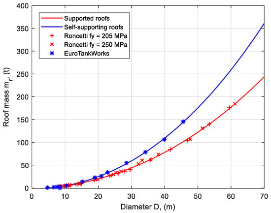
Data about the mass of self-supporting roofs can be gathered from the site of “EuroTankWorks” [34] and are presented in Table 2. The storage tanks are those with conical roofs except those with large diameter, which are spherical. The data for each case is converted into a mass in kg for the whole roof structure and approximation functions are identified using the MATLAB® R2017a software function “fit” [35]. The mass of the roofs should be approximately proportional to the square of the diameter, but in order to be more precise, cubic polynomials have been chosen.
Table 2.
Masses of self-supporting roofs with conical and spherical shapes [34].
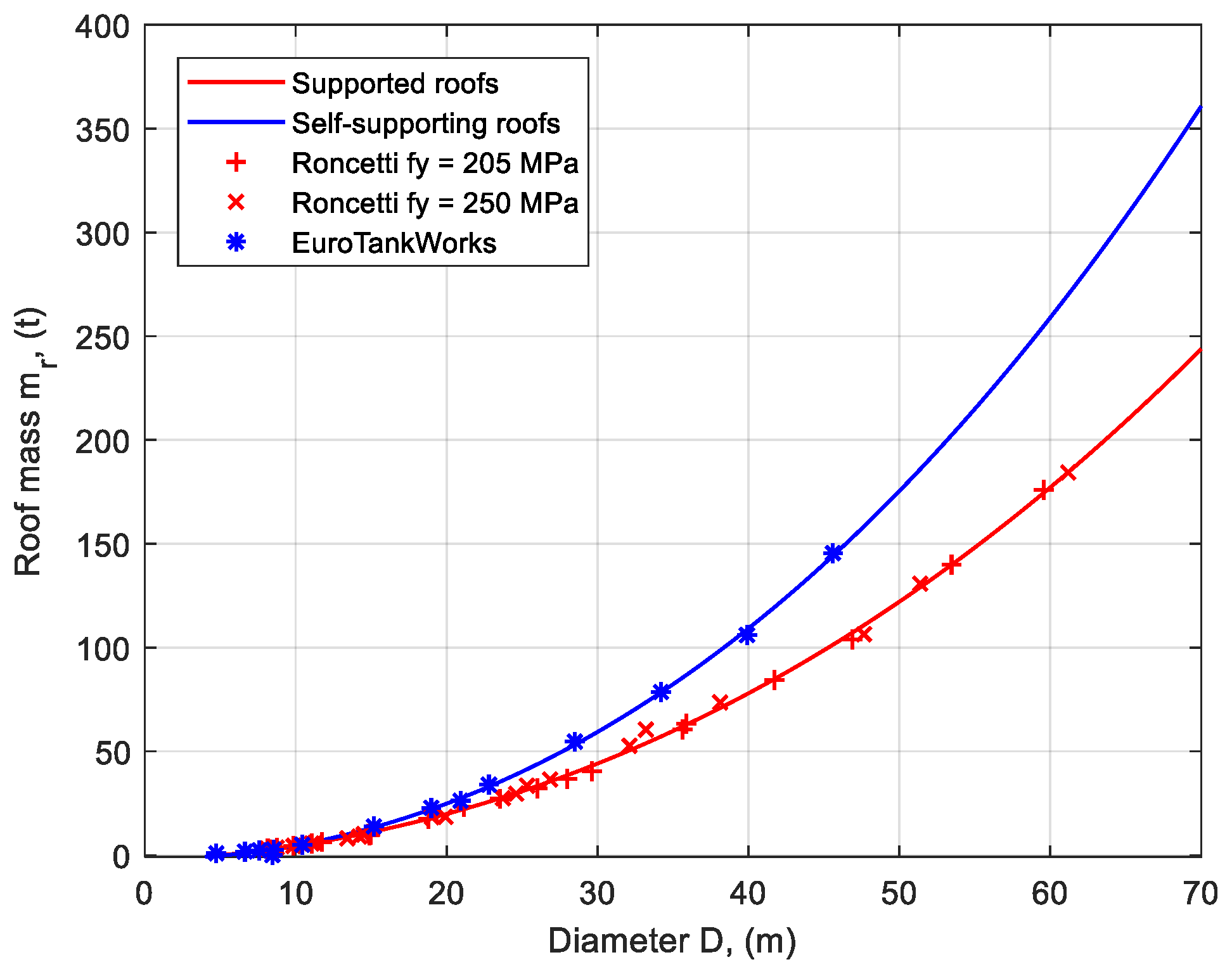
The fitting of the data to the curves of the cubic functions is illustrated in Figure 2. The visual inspection shows very good agreement between the data and the curves. The adjusted R-squared factor is 0.9986 for the supported roofs and 0.9989 for the self-supporting roofs, which means a high goodness-to-fit indicator. These functions are used to calculate the mass of the roof, , as a function of the diameter, , of the storage tank. The open-top tanks considered here have a zero-roof mass in the mass calculations.
Figure 2.
Approximations of roof masses.
For simplicity, we assume a conical roof for all storage tanks, with a slope of for all supported roofs and for all self-supporting roofs. Because the slope determines the height-to-radius ratio of the conical roofs, , the heights of the roofs are assumed to be and the mass center as , so the roof mass center height from the bottom of the tank is:
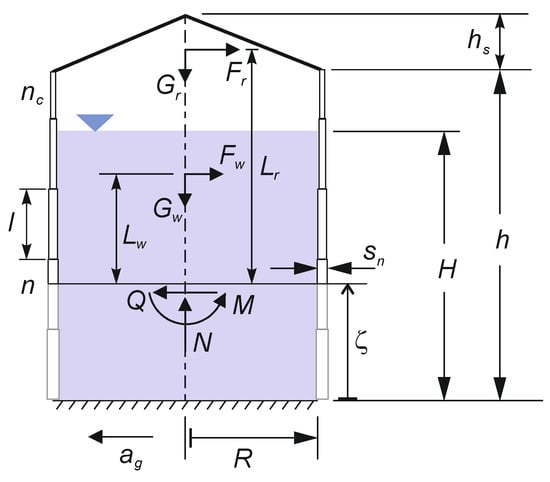
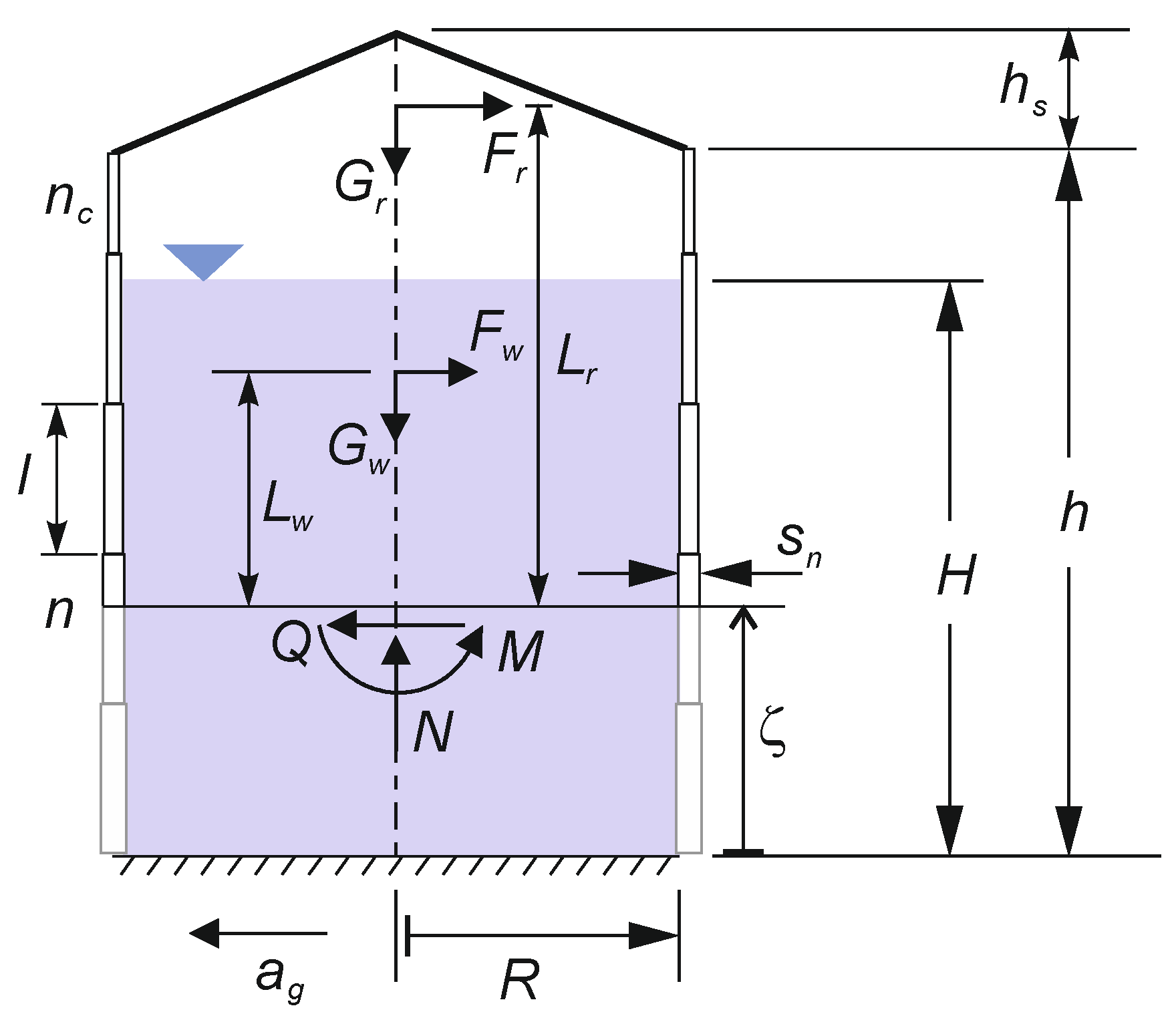
The inertial and gravity forces of the roofs are given in Figure 3. The inertial force can be calculated from the roof mass as due to the rigidity of the roof, as well as the entire storage tank. The gravity force or weight is . The distance of the mass center of the roof to the cross-section at the relative coordinate, , is:
Figure 3.
Meridional section of storage tank with gravity and inertial forces, as well as cross-sectional resultants.
3.2. Shell Courses of the Wall and the Bottom of the Storage Tank
The height of the storage tank cylinder is divided into shell courses with widths of m, excluding the top course. They have different thicknesses, but initially a uniform thickness, can be assumed. The shell thickness should be selected from the order of standard steel sheet thicknesses: 1.5, 2, 2.5, 3, 4, 5, 6, 7, 8, 9, 10, 11, 12, 14, 15, 16, 18, 20, 22, 25, 28, 30, 32, 35, 38, 40, 45, 50, 55, 60, and 65 mm. The number of courses is . The total mass of the tank wall cylinder is (Figure 3):
where is the thickness of each shell course; kg/m3 is the mass density of the steel; and is the width of the top shell course, .
The current mass of the wall from the cross-section at to the top can be calculated as (Figure 3):
where is the current shell course number at the cross-section; and is the width of the upper part of the current shell course cut at the cross-section. The mass center of the upper part of the cut wall is at distance, , from the cross-section at relative coordinate, :
where the inertial force and the gravity force are applied. The last two members of Equations (31) and (32) disappear when .
The bottom of the storage tank is considered as a circle of steel sheet with uniform thickness. The bottom mass can be calculated easily as:
where mm is the minimum thickness allowed for steel storage tank bottom, according to the EC 3-4-2 [36].
3.3. Cross-Sectional Resultants
The axial resultant force, , of the cross-section at a relative coordinate, , is simply the sum of a part of the roof weight, , and the current wall weight, , as a compressive force:
where the participation factor, , is 0.2 for the supported roofs (20% of the weight is transferred to the wall) and 1.0 for the self-supporting roofs.
The transverse shear force, , can be calculated as:
where
The transverse shear force, , however, will cause a shear stress, whose maximum is not at the meridional section in the direction of the seismic action where the normal membrane stresses have their maximum. Therefore, the shear force as well as the shear stress calculations will be omitted.
The total bending moment, , of the cross-section at a relative coordinate, can be calculated by the expression:
where
The integrations in Equations (36) and (38) can be realized numerically in MATLAB® by using the function “trapz” [35]. The bending moment, , will cause normal meridional stresses, which, when combined with the compressive stresses from the axial force, , could cause buckling of the wall of the storage tank.
4. Stress and Strength of Tank Wall
4.1. Shell Membrane Stresses
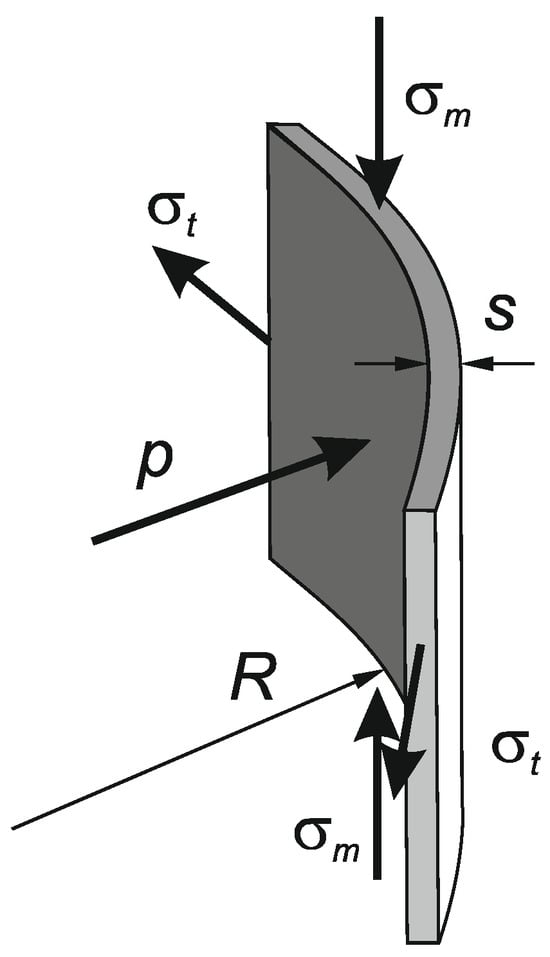
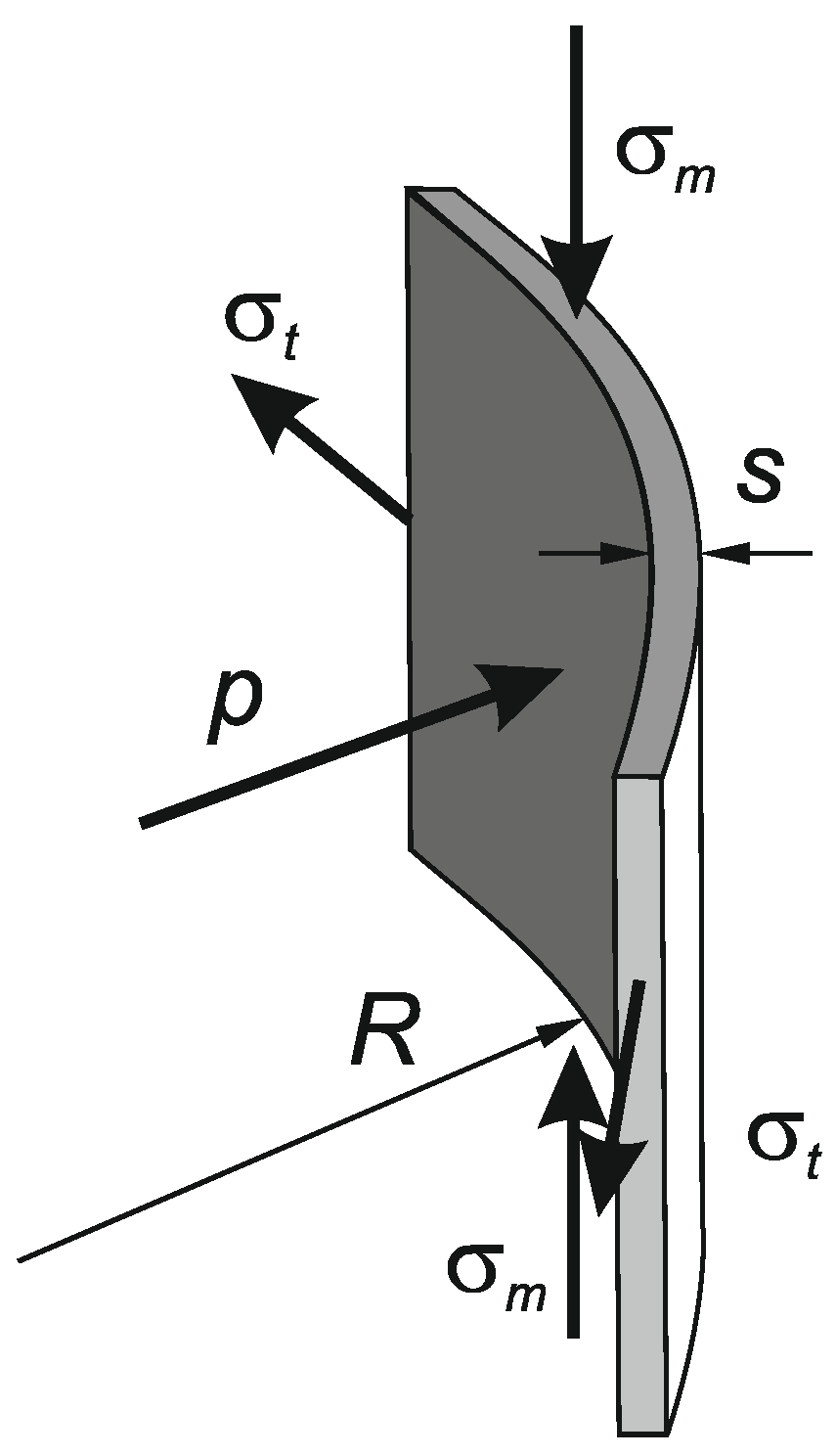
The fluid pressure on the tank wall will cause hoop stress, , (see Figure 4), which can be expressed as:
Figure 4.
Membrane stresses—, meridional stress; , hoop stress—on an elementary segment of storage tank wall.
The axial load and the bending moment will cause a compressive axial stress in the meridional section, , (see Figure 4), according to EC 3-1-6 [37]:
4.2. Plasticity Criterion
The strength condition is based on the von Mises yield criterion, which is evaluated using the equivalent stress, [37]:
where the meridional stress, , is compressive. The design could be governed by the inequality
which can be used in an iterative procedure to determine with rapid convergence:
The buckling conditions are two different types: elastic buckling, using the minimum pressure, ; and elastic–plastic buckling (“elephant foot”), using the maximum pressure of the fluid, .
4.3. Elastic Buckling
The inequality that should be met is:
where
is the ideal critical stress for axially loaded cylinders [37]. The stress
accounts for the influence of the hoop stress and pressure, where
By introducing the parameter
we can calculate
where
accounts for the imperfections of the wall. Here, is the ratio of the maximum imperfection amplitude, , to the wall thickness, . This ratio can be determined by the empirical formula:
where
4.4. Elastic–Plastic Buckling
The elastic–plastic buckling type or “elephant’s foot” is caused by high pressure on the wall combined with a meridional compressive stress. The empirical formula for the critical meridional stress, , and the inequality condition is:
where is the ratio ; and and are in MPa.
5. Optimization Procedure
5.1. Storage Tank Design Calculations
The above-mentioned formulae are programmed in MATLAB® scripts to calculate necessary wall thicknesses and masses of all parts of a designed storage tank for a given volume capacity and slenderness ratio. Different storage tank volume capacities are selected in the range , with a considered total of 100 cases. Different height-to-radius (slenderness) ratios are selected for each storage tank volume, which are 150 in the range of . The optimization procedure consists of scanning 15,000 storage tank configurations for one case of seismic loading and steel grade.
The stress calculation points are 200, uniformly distributed in the range of for each storage tank size. For each calculation point, the pressure and the membrane stresses are determined with the current thickness of the shell course. The strength conditions are checked and, if they are not satisfied, a greater thickness is selected from the range of standard sheet material thicknesses; that is, 1.5 65 mm until all strength conditions are satisfied for all calculation points in an iteration procedure. The thickness of the last course determined by the calculation points is assumed to be the thickness of all the other top shell courses on the freeboard, if any.
The fluid is petrol fuel with a mass density . The optimal design of storage tanks is investigated for three reference seismic accelerations , with an importance factor . The reference seismic accelerations approximately correspond to the different seismic zones of the Mediterranean and Southeast European countries appointed in their National Annexes of EC 8-1. The elastic response spectrum is type I for soil class C, and the behavior factor accepted here is . The tanks are made of structural steel with three different grades: S235, S275, and S355 ( MPa, 275 MPa, and 355 MPa). The accepted partial safety factor is ; the modulus of the elasticity of steel is GPa; the mass density of the steel is ; and the shell course width is m with a construction quality of .
The optimal design of a storage tank plant with a total volume capacity of 30,000 m3 also will be considered. Here, we will evaluate the optimal configuration across one to five tanks providing the same total volume capacity.
5.2. Optimization Criterion
The simplest criterion for optimizing cylindrical storage tanks is the mass of the tank, which should be minimized, thereby optimizing both material and labor costs considered to be proportional to the material. Here, the total mass of the storage tank is:
However, the mass of the storage tank is proportional to the volume capacity of the tank, which could also be a parameter for optimization. Therefore, the mass of the tank alone might not be the suitable criterion, especially when the capacity of the tank is one of the optimization parameters. A more appropriate criterion would be the relative mass, defined as the tank’s mass per its volume capacity:
Even if this criterion is transformed into an economic criterion by multiplying the mass by cost per unit mass of steel, a valid criterion as expenses per unit volume capacity will be obtained, i.e., the price of the tank capacity, which could be minimized. The economic criterion, , can be divided into the costs of roof materials and fabrication, ; the expenses of wall materials and erection, ; and the costs of the land, foundation, and bottom assembly, , which may also include the costs of adjacent pipeline infrastructure:
However, specific costs of individual parts of a storage tank depend on the accepted technology when building the tank, which is specific for the building company. This is why the investigation here will be restricted to the criterion determined by Equation (54) only.
The optimization problem can be stated as the minimization of an objective function with constraints:
where and are the parameters of optimization. The thicknesses of the shell courses, , are also parameters of optimization, but they are directly determined from the constraints as minimal values satisfying the strength conditions. The thickness, , and the number of the shell courses, , have discrete values, which means that the surface of the objective function could not be smooth in the parametric space of and . Most of the known optimization methods are not applicable for such objective functions; therefore, the scanning method is very useful. Then, a nice smooth surface of the objective function can be found as an approximation, and the other methods can be applied.
6. Results
The minimums of the objective function found by scanning the parametric space for each combination of seismic loading and steel grade are given in Table 3 for the supported roof storage tanks, in Table 4 for the self-supporting roof tanks, and in Table 5 for the open-top tanks. The calculations were done on a workstation computer with 2 Intel® Xeon® CPU E5-2667 v4 @ 3.2 GHz processors and RAM 64 GB DDR4 @ 1200 MHz for approximately 10 min per all roof cases and one case of seismic loading and steel grade. The total time for all calculations was 90 min.
Table 3.
Minimums of criterion for supported roof storage tanks.
Table 4.
Minimums of criterion for self-supporting roof storage tanks.
Table 5.
Minimums of criterion for open-top storage tanks.
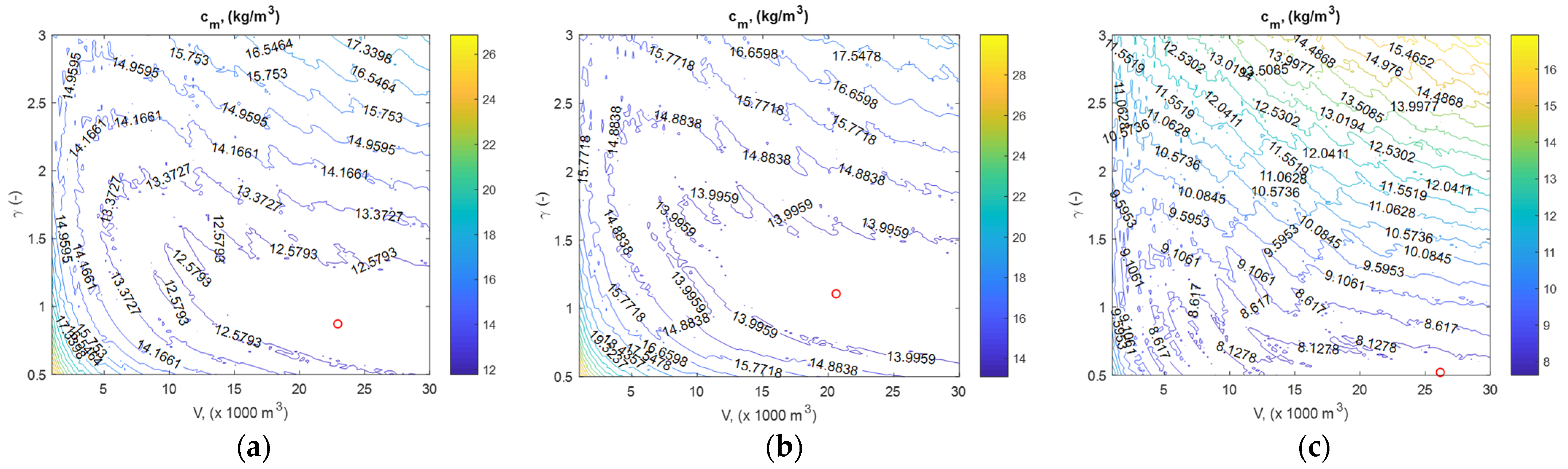
The results of the relative mass criterion calculations for each designed storage tank can be illustrated as contour plots, as shown in Figure 5. The minimum of the criterion is marked as a red circle. The contours are very jagged due to the discrete values of the shell course thicknesses and the different number of the shell courses. Also, many small areas with a local minimum of the criterion are observed, which could explain the difficulty to apply some optimization methods to find the global minimum.
Figure 5.
Contour plots of criterion with minimums, shown by red circles, for cases of and MPa: (a) supported roofs; (b) self-supporting roofs; (c) open-top storage tanks.
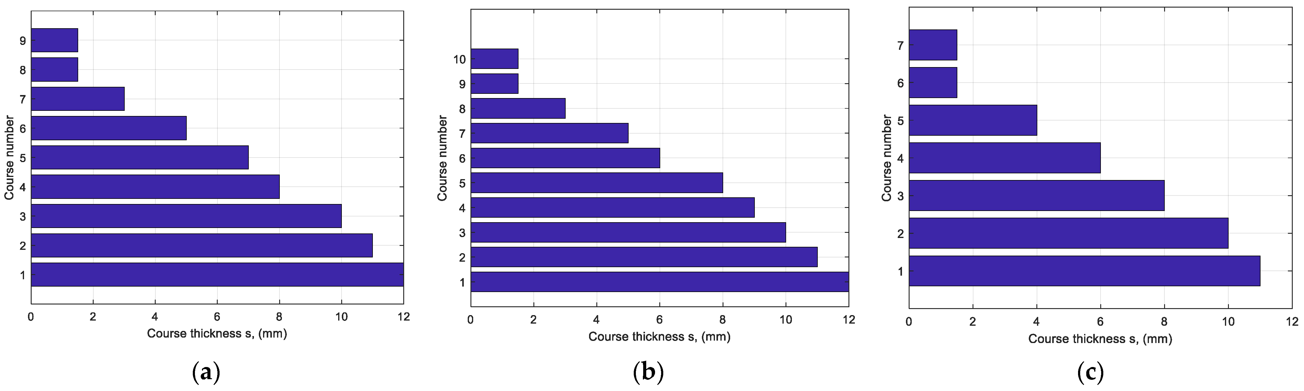
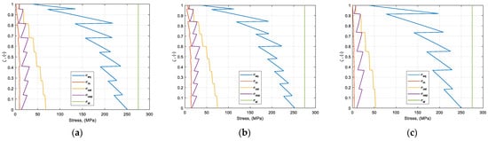
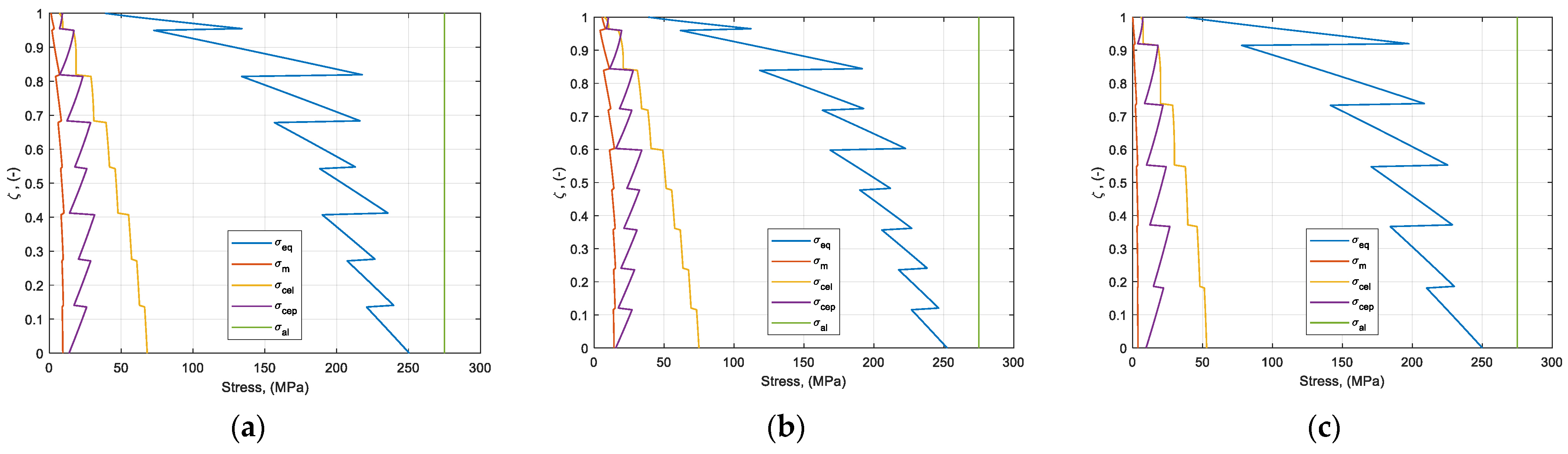
The optimal storage tank design with all shell course thicknesses can be seen in Figure 6 for the case of loading with a reference ground acceleration and structural steel grade S275. The different discrete thicknesses of the shell courses of the wall cause jagged diagrams of all stress distributions, which can be seen in Figure 7. The strongest strength restriction of the stresses is the critical elastic–plastic buckling stress limiting the meridional stress. The stresses near the fluid level are negligible, and the minimum sheet thickness is enough to satisfy the strength requirements. The same thickness is chosen for the freeboard shell course of the wall.
Figure 6.
Number of shell courses and their thicknesses for cases of and MPa: (a) supported roofs; (b) self-supporting roofs; (c) open-top storage tanks.
Figure 7.
Stresses in the designed storage tank walls for cases of and MPa: (a) supported roofs; (b) self-supporting roofs; (c) open-top storage tanks.
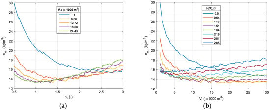
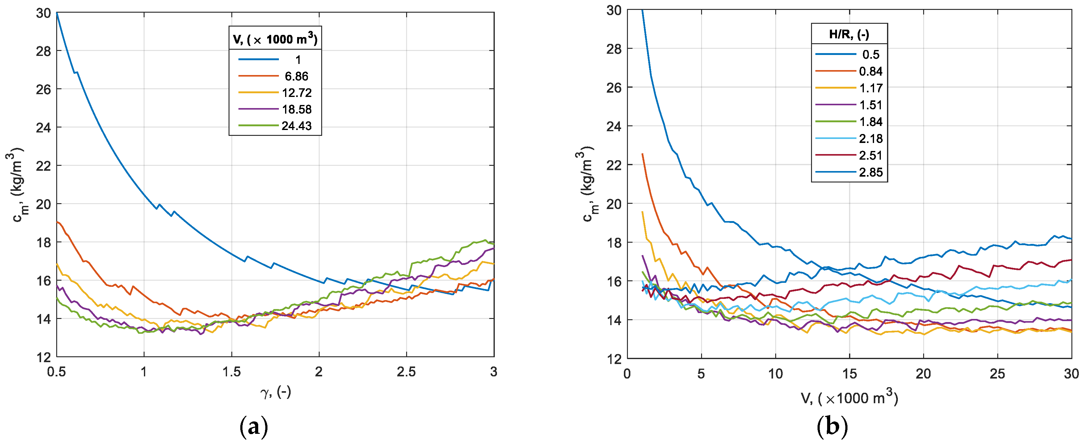
In order to deeply understand the character of the criterion dependency on the optimization parameters and , sections of the criterion surface can be drawn at different constant values of one of the parameters and then the other. The curves of the sections can be seen in Figure 8. All sections of the criterion surfaces have similar curled curves, so only the sections of one criterion surface are given. Though the curves are curled, if they are smoothed, they will become curves with slightly changing curvature, which means that they can be approximated by cubic polynomials in a regression analysis. The regression functions should be as simple as possible in order to be used for simple calculations by hand while as precise as possible at the same time.
Figure 8.
Sections of criterion surfaces for self-supporting roofs and cases of and MPa: (a) functions of at fixed ; (b) functions of at fixed .
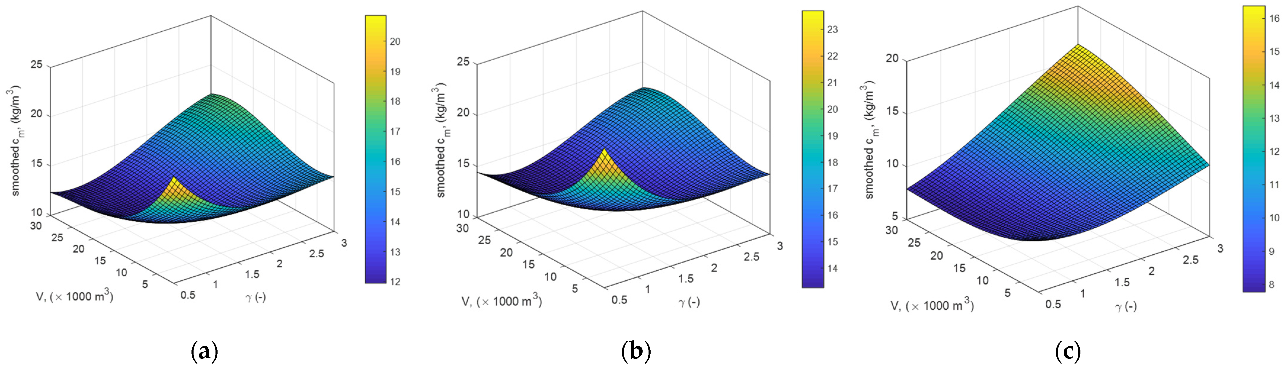
When looking for a smooth surface, by describing the relative mass criterion changes, a surface defined by a bi-cubic polynomial function is decided to be fitted to the calculated data of the parametric space scanning:
where and , so that is in . These surfaces look like those in Figure 9. The coefficients of the bi-cubic functions are given in Table 6 for the case of the loading with a reference ground acceleration and structural steel grade S275.
Figure 9.
Smoothed surfaces of criterion for cases of and MPa: (a) supported roofs; (b) self-supporting roofs; (c) open-top storage tanks.
Table 6.
Coefficients of fitted criterion functions for cases of and MPa.
The correlation between the smoothed objective function, , from Equation (57) and the scanned surface of can be justified by the adjusted R-square factor in regression analysis. The adjusted R-square factor is 0.9550 for the storage tanks with supported roofs, 0.9498 for the tanks with self-supporting roofs, and 0.9938 for open-top storage tanks when the reference ground acceleration is and structural steel grade is S275. These are very good fits, and the smoothed objective functions can be used for further analysis and optimizations. The smoothed objective functions are obtained for all cases of loadings and steel grades, as well as for all cases of roofs. Constrained optimization is applied by using the “fmincon” function of MATLAB® in order to find the minimum of the smoothed objective functions with starting points of the calculated minimums. The obtained minimums of the smoothed functions are given in Table 3, Table 4 and Table 5.
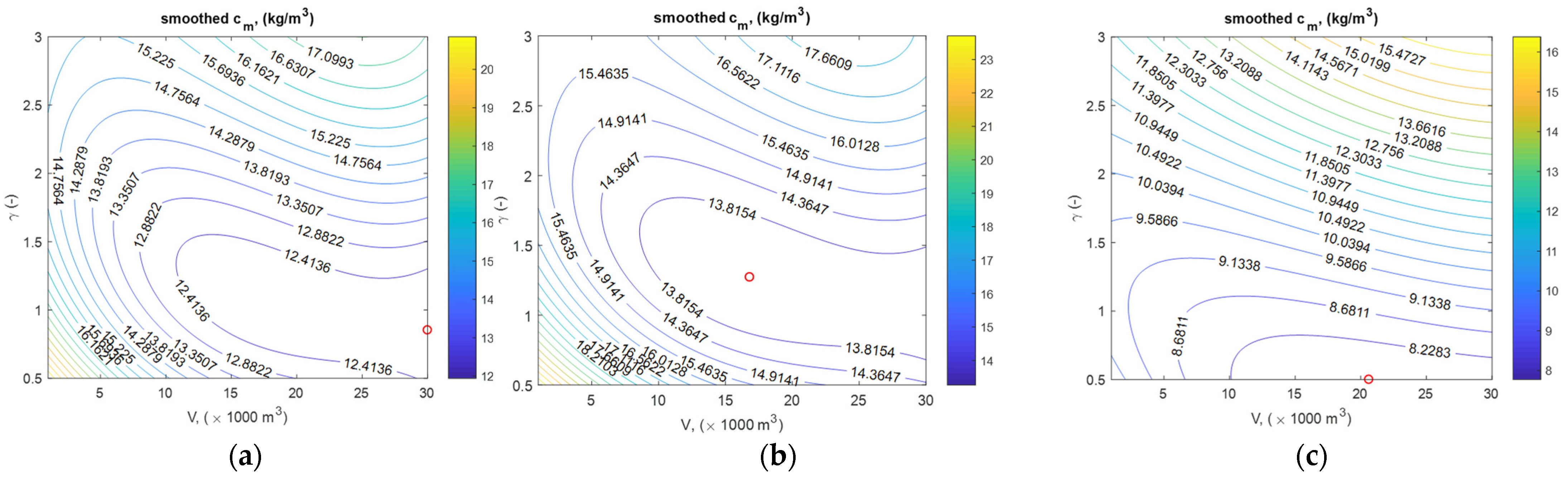
The nice smooth surfaces in Figure 9 can be visualized using contour plots with the minimum of the smoothed relative mass criterion marked on them. The plots are given in Figure 10. The minimum of the smoothed criterion for supported roof storage tanks is found at the maximum of the volume capacity (Figure 10a), while for open-top storage tanks, the minimum is at the minimum of the slenderness ratio (Figure 10c). For all roof cases, one can conclude that the optimal slenderness ratio is lower when the volume capacity is higher.
Figure 10.
Smoothed contour diagrams of criterion with minimums, shown by red circles, for cases of and MPa: (a) supported roofs; (b) self-supporting roofs; (c) open-top storage tanks.
Comparing the plots in Figure 10 with the corresponding plots in Figure 5, one can see the same tendency of the criterion change. The discrepancy of the criterion minimum is mainly due to the discrete wall thicknesses of the storage tanks. Comparing the minimum values of the calculated and the smoothed criteria in Table 3, Table 4 and Table 5, one can see that they are very close each other. The minimum of the relative mass criterion is higher for a higher seismic loading and for a lower strength of the steel (yield stress of the material). The minimum of the relative mass criteria, both calculated and smoothed, for supported roof tanks is reached at the maximum volume capacity, as can be seen in Table 3 and confirmed by Figure 10a. The minimum of the criteria for open-top tanks, according to Table 5, is when the slenderness ratio has a minimum value and that corresponds to Figure 10c.
The discrepancy between the calculated and smoothed values of the volume capacity, as well as the slenderness ratio for optimal storage tanks, when they do not have extreme values is maybe high, according to Table 3, Table 4 and Table 5, but this is due to the very low sensitivity of the relative mass criterion to the volume capacity and the slenderness ratio at the point of its minimum. This can be seen in Figure 10 as a very large area of the lowest range of the criterion values. Comparing the width of the area with the lowest value range of the criterion (a volume capacity range) with the height of the same area (a range of the slenderness ratio) at the minimum point of the criterion (the red circle in the plot), one can conclude that the sensitivity of the criterion to the volume capacity is lower than to the slenderness ratio.
Sensitivity analysis of the smoothed relative mass criterion is carried out with respect to single parameters for all roof, seismic loading, and steel grade cases. The sensitivity factors have the meaning of a criterion percentage change per 1% parameter disturbance. They are calculated as follows:
where is the disturbance, while and are the optimal parameters of the smoothed criterion, . The sensitivity factors are given in Table 7 for cases of and MPa on 5% basis of disturbance (.
Table 7.
Sensitivity factors for and for cases of and MPa.
The sensitivity of the relative mass criterion to the volume capacity is an order higher than the sensitivity to the slenderness ratio for tanks with supported roofs. The sensitivity of the criterion to slenderness ratio is higher than the sensitivity to capacity for tanks with self-supporting roofs and open-top tanks. The sensitivity of the criterion is investigated for all cases and for different disturbances: 1%, 2%, 5%, 10%, and 20%. The sensitivity factors increase with the disturbance increase; however, they are very similar for the different cases of loading and steel grade, and therefore only the results for 5% disturbance are given.
7. Discussion
The results of the optimization exhibited in the previous section can be used directly to pick up the optimal configuration of the storage tank. The optimization parameters can be corrected if necessary, in a degree corresponding to the data in Table 3, Table 4 and Table 5. For instance, if the storage tank is for water, which has a higher mass density and causes a higher loading, or simply the seismic hazard loading of the site is higher than that accepted here, then the slenderness ratio can be lowered a little bit.
The choice of an optimal configuration of the storage tank in design should be followed by the design of the roof structure, if one is included. From this, the calculations of the wall thicknesses using Eurocode 8-4 for a rigid tank should be done as per the optimization procedure here. Once the wall thicknesses are known, the tank can be considered as flexible, with the flexible pressure to be calculated and eventually new wall thicknesses to be determined. The last design process could include soil–structure interaction for a designed foundation and known soil properties. The final design of the storage tank can be validated by FEM using a suitable approach, such as the added mass method or time-history simulations with different accelerograms. Instead of Eurocode 8-4, some other standard provisions are also applicable because they are based on the same fluid–structure interaction model.
Usually, the choice of the storage tank capacity in design is not a matter of optimization but a matter of meeting needs. When deciding on the volume capacity of the tank, its optimal height-to-radius ratio should be found in order to achieve minimum mass and minimum costs. Then, the type of roof structure for the tank should be determined.
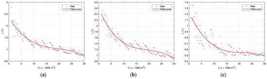
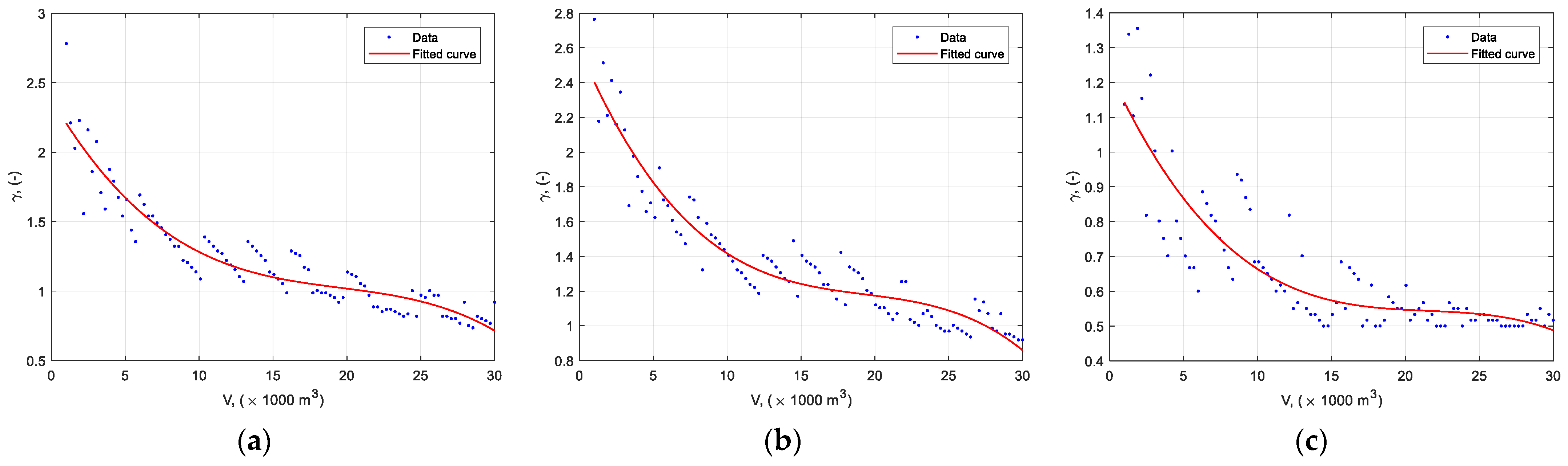
The optimal slenderness ratios, which determines the minimum mass of the tank for each volume capacity, can be found through the calculated configurations of tanks. These optimal slenderness ratios as a function of capacity can be approximated by a cubic polynomial applying a regression analysis. The function of the optimal slenderness ratio, (–), with respect to the volume capacity of the tank, has the form:
where . The fitted curves to the scattered data are depicted in Figure 11, and the coefficients of the functions are given in Table 8 for the case of seismic loading with and steel with MPa. The goodness-to-fit indicator adjusted R-square is 0.8306 for tanks with supported roofs, 0.8421 for self-supporting roof tanks, and 0.8169 for open-top tanks.
Figure 11.
Fitting curves and data points for optimal slenderness ratio functions for cases of and MPa: (a) supported roofs; (b) self-supporting roofs; (c) open-top storage tanks.
Table 8.
Coefficients of optimal slenderness ratio function for cases of and MPa.
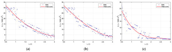
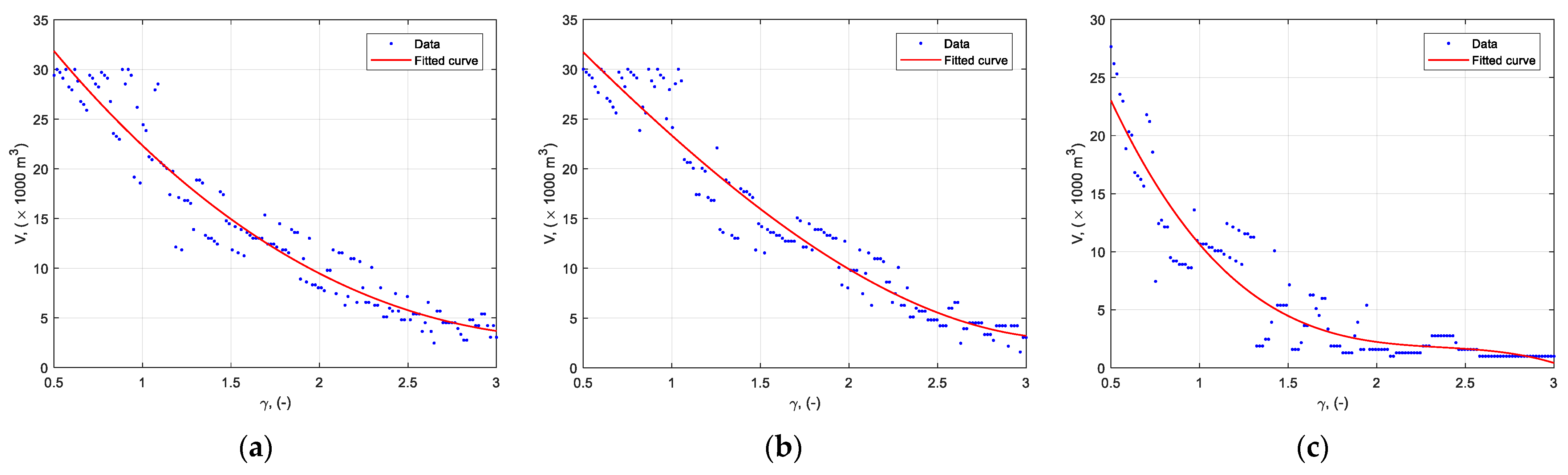
Similar to Equation (59), an inverse relationship between the optimal capacity volumes and the height-to-radius ratios of the storage tanks can be derived. It is necessary to determine the optimal values of the capacity for each slenderness ratio examined and then fit a curve of a cubic function to the data. The approximation function found is:
where , so that () is the optimal volume capacity for a given slenderness ratio of a storage tank. The coefficients of the function are given in Table 9, and the graphics of the curves fitted to the data are shown in Figure 12. The adjusted R-square factor is 0.9173 for tanks with supported roofs, 0.9364 for self-supporting roof tanks, and 0.9169 for open-top tanks, which means that there is a good fitting.
Table 9.
Coefficients of optimal volume capacity function for cases of and MPa.
Figure 12.
The fitting curves and data points for optimal volume capacity function for case of and MPa: (a) supported roofs; (b) self-supporting roofs; (c) open-top storage tanks.
The derived functions (59) and (60) can be very useful in solving practical optimization problems in the design of storage tanks. Such a practical problem is the optimization of the number of storage tanks with the same volume capacity in a storage plant with a total volume capacity.
The problem that we want to solve is to finding the optimal number of the storage tanks that have equal volume capacity and self-supporting roofs when the total set volume capacity is 30,000 m3. The seismic loading at the site is considered as a reference ground acceleration and the steel grade of the storage tank wall is S275. There are two approaches to solve this problem. The first one is to use the MATLAB® scripts developed here to design multiple storage tanks with different slenderness ratios for each volume capacity and to find the minimum mass per volume criterion, , for each single tank volume capacity, . Then, the height-to-radius ratio, , of the found minimum criterion can be determined. The second approach is to use Equation (59) in order to find the optimal slenderness ratio, , for each single storage tank volume capacity, , and then design a storage tank with such parameters, calculating its relative mass criterion, . The results of both approaches when applied are shown in Table 10.
Table 10.
Optimization of the number of self-supporting roof storage tanks in a plant of total volume capacity, , for cases of and MPa.
The data in Table 10 show that when applying the first approach, it is the best to have only one storage tank with maximum capacity. This conclusion coincides with that of Roncetti [29]. The second approach determines the minimum steel consumption when there are two storage tanks. The minimum values of the relative mass criterion for the different number of tanks in the plant do not differ much, no more than 6% for both approaches, and the difference between the criteria for the two approaches is also no more than 6%. The slenderness ratios for the two approaches are also relatively close.
The similar values of the relative mass criterion of storage tanks for different numbers of tanks show that the decision on how many tanks there should be can also be made based on other considerations. One reason to have more storage tanks is that they are easier to maintain, as there is always a reserve when one tank needs to be emptied for maintenance. On the other hand, if we have more storage tanks, we will have a larger and more expensive pipe infrastructure.
The results of the optimization and the functional relationships presented here should serve only as a guide for finding the optimal solution when designing storage tanks. Any deviation from the parameters specified here should be evaluated, and appropriate adjustments should be made to achieve a better result.
Author Contributions
Conceptualization, methodology, visualization, investigation, writing—original draft, I.I.; data curation, validation, writing—review and editing, D.V. All authors have read and agreed to the published version of the manuscript.
Funding
This study is financed by the European Union—NextGenerationEU, through the National Recovery and Resilience Plan of the Republic of Bulgaria, project No. BG-RRP-2.013-0001.
Data Availability Statement
Data is not publicly available.
Conflicts of Interest
The authors declare no conflicts of interest.
Abbreviations
The following abbreviations are used in this manuscript:
| API | American Petroleum Institute |
| EC | Eurocode |
| FEM | Finite Element Method |
| PGA | Peak Ground Acceleration |
References
- Brunesi, E.; Nascimbene, R.; Pagani, M.; Beilic, D. Seismic performance of storage steel tanks during the May 2012 Emilia, Italy, earthquakes. J. Perf. Constr. Facil. 2014, 29, 04014137. [Google Scholar] [CrossRef] [Scilit]
- Hamdan, F.H. Seismic behaviour of cylindrical steel liquid storage tanks. J. Constr. Steel Res. 2000, 53, 307–333. [Google Scholar] [CrossRef] [Scilit]
- Dizhur, D.; Simkin, G.; Giaretton, M.; Loporcaro, G.; Palermo, A.; Ingham, J. Performance of winery facilities during the 14 November 2016 Kaikōura earthquake. Bull. N. Z. Soc. Earthq. Eng. 2017, 50, 206–224. [Google Scholar] [CrossRef] [Scilit]
- Miladi, S.; Razzaghi, M.S. Failure analysis of an un-anchored steel oil tank damaged during the Silakhor earthquake of 2006 in Iran. Eng. Fail. Anal. 2019, 96, 31–43. [Google Scholar] [CrossRef] [Scilit]
- Changa, J.I.; Lin, C.C. A study of storage tank accidents. J. Loss Prev. Proc. Indust. 2006, 19, 51–59. [Google Scholar] [CrossRef] [Scilit]
- González, E.; Almazán, J.; Beltrán, J.; Herrera, R.; Sandoval, V. Performance of stainless steel winery tanks during the 02/27/2010 Maule Earthquake. Eng. Struct. 2013, 56, 1402–1418. [Google Scholar] [CrossRef] [Scilit]
- Çelik, A.İ.; Akgül, T.; Apay, A.C. Plastic deformation of cylindrical steel tank both under the Kocaeli and el-Centro earthquake. Int. J. Adv. Eng. Res. Devel. 2018, 5, 27–35. [Google Scholar]
- Yan, P.; Guo, E.; Wu, H.; Zhang, L. Numerical simulation of the seismic response of a horizontal storage tank based on a SPH–FEM coupling method. Comput. Model. Eng. Sci. 2024, 139, 1655–1678. [Google Scholar] [CrossRef] [Scilit]
- Sobhan, M.S.; Rofooei, F.R.; Attari, N.K.A. Buckling behavior of the anchored steel tanks under horizontal and vertical ground motions using static pushover and incremental dynamic analyses. Thin-Wall. Struct. 2017, 112, 173–183. [Google Scholar] [CrossRef] [Scilit]
- Yu, C.-C.; Mir, F.U.H.; Whittaker, A.S. Validation of numerical models for seismic fluid-structure-interaction analysis of nuclear, safety-related equipment. Nucl. Eng. Des. 2021, 379, 111179. [Google Scholar] [CrossRef] [Scilit]
- Malhotra, P.K.; Wenk, T.; Wieland, M. Simple Procedure for Seismic Analysis of Liquid-Storage Tanks. Struct. Eng. Int. 2000, 10, 197–201. [Google Scholar] [CrossRef] [Scilit]
- Colombo, J.I.; Almazán, J.L. Seismic reliability of continuously supported steel wine storage tanks retrofitted with energy dissipation devices. Eng. Struct. 2015, 98, 201–211. [Google Scholar] [CrossRef] [Scilit]
- Vathi, M.; Karamanos, S.A. A simple and efficient model for seismic response and low-cycle fatigue assessment of uplifting liquid storage tanks. J. Loss Prev. Proc. Indust. 2018, 53, 29–44. [Google Scholar] [CrossRef] [Scilit]
- Housner, G.W. The dynamic behavior of water tanks. Bull. Seism. Soc. Am. 1963, 53, 381–387. [Google Scholar] [CrossRef] [Scilit]
- Yang, J.Y. Dynamic Behavior of Fluid-Tank Systems. Ph.D. Thesis, Rice University, Houston, TX, USA, 1976. [Google Scholar]
- Veletsos, S.; Yang, J.Y. Earthquake response of liquid storage tanks. In Proceedings of the Advances in Civil Engineering Through Engineering Mechanics, ASCE, Raleigh, NC, USA, 23–25 May 1977. [Google Scholar]
- Haroun, M.A.; Housner, G.W. Earthquake response of deformable liquid storage tanks. J. Appl. Mech. 1981, 48, 411–417. [Google Scholar] [CrossRef] [Scilit]
- Veletsos, A.S. Seismic response and design of liquid storage tanks. In Guidelines for the Seismic Design of Oil and Gas Pipeline Systems; Technical Council on Lifeline Earthquake Engineering, ASCE: New York, NY, USA, 1984; pp. 255–370, 443–461. [Google Scholar]
- Moreno, M.; Colombo, J.; Wilches, J.; Reyes, S.; Almazan, J. Buckling of steel tanks under earthquake loading: Code provisions vs FEM comparison. J. Constr. Steel Res. 2023, 209, 108042. [Google Scholar] [CrossRef] [Scilit]
- Spritzer, J.M.; Guzey, S. Nonlinear numerical evaluation of large open-top aboveground steel welded liquid storage tanks excited by seismic loads. Thin-Wall. Struct. 2017, 119, 662–676. [Google Scholar] [CrossRef] [Scilit]
- Hosseinzadeh, N.; Kazem, H.; Ghahremannejad, M.; Ahmadi, E.; Kazem, N. Comparison of API650-2008 provisions with FEM analyses for seismic assessment of existing steel oil storage tanks. J. Loss Prev. Proc. Indust. 2013, 26, 666–675. [Google Scholar] [CrossRef] [Scilit]
- Wunderlich, W.; Seiler, C. Nonlinear treatment of liquid-filled storage tanks under earthquake excitation by a quasistatic approach. Comp. Struct. 2000, 78, 385–395. [Google Scholar] [CrossRef] [Scilit]
- Djermane, M.; Zaoui, D.; Labbaci, B.; Hammadi, F. Dynamic buckling of steel tanks under seismic excitation: Numerical evaluation of code provisions. Eng. Struct. 2014, 70, 181–196. [Google Scholar] [CrossRef] [Scilit]
- Sivý, M.; Musil, M. Seismic resistance of storage tanks containing liquid in accordance with principles of Eurocode 8 standard. J. Mech. Eng. 2016, 66, 79–88. [Google Scholar] [CrossRef] [Scilit]
- Nachtigall, I.; Gebbeken, N.; Urrutia-Galicia, J.L. On the analysis of vertical circular cylindrical tanks under earthquake excitation at its base. Eng. Struct. 2003, 25, 201–213. [Google Scholar] [CrossRef] [Scilit]
- Daryavarsari, S.F.; Nascimbene, R. Assessment of steel storage tank thickness obtained from the API 650 design procedure through nonlinear dynamic analysis, accounting for large deformation effects. Materials 2025, 18, 66. [Google Scholar] [CrossRef] [Scilit]
- EN 1998-4:2006; Eurocode 8—Design of Structures For Earthquake Resistance—Part 4: Silos, Tanks and Pipelines. European Committee for Standardization: Brussels, Belgium, 2006.
- API 650:2021; Welded Tanks for Oil Storage. American Petroleum Institute: Washington, DC, USA, 2021.
- Roncetti, L. Structural and economical optimization of welded steel storage tanks. In Proceedings of the 21st Brazilian Congress of Mechanical Engineering, Natal, RN, Brazil, 24–28 October 2011. [Google Scholar]
- API 650:2007; Welded Tanks for Oil Storage. American Petroleum Institute: Washington, DC, USA, 2007.
- EN 1998-1:2004; Eurocode 8—Design of Structures for Earthquake Resistance—Part 1: General Rules. Seismic Actions and Rules for Buildings: Brussels, Belgium, 2004.
- Chatterji, S.; Butenweg, C.; Klinkel, S. Unified force-based design approach for the seismic analysis and design of liquid storage tanks. Bull. Earthq. Eng. 2025, 23, 2377–2420. [Google Scholar] [CrossRef] [Scilit]
- Rawat, A.; Matsagar, V.; Nagpal, A.K. Seismic analysis of steel cylindrical liquid storage tank using coupled acoustic-structural finite element method for fluid-structure interaction. Int. J. Acoust. Vib. 2020, 25, 27–40. [Google Scholar] [CrossRef] [Scilit]
- EuroTankWorks Storage Tanks & Silos Mfr. Vertical Site Built Above-Ground Storage Tanks. Available online: https://eurotankworks.com/storage-tanks/vertical-storage-tanks/ (accessed on 28 January 2026).
- The MathWorks Inc. Available online: https://www.mathworks.com/help (accessed on 28 January 2026).
- EN 1993-4-2:2007; Eurocode 3: Design of Steel Structures—Part 4–2: Tanks. European Committee for Standardization: Brussels, Belgium, 2007.
- EN 1993-1-6:2007; Eurocode 3: Design of Steel Structures—Part 1–6; Strength and Stability of Shell Structures. European Committee for Standardization: Brussels, Belgium, 2007.

Disclaimer/Publisher’s Note: The statements, opinions and data contained in all publications are solely those of the individual author(s) and contributor(s) and not of MDPI and/or the editor(s). MDPI and/or the editor(s) disclaim responsibility for any injury to people or property resulting from any ideas, methods, instructions or products referred to in the content. |
© 2026 by the authors. Licensee MDPI, Basel, Switzerland. This article is an open access article distributed under the terms and conditions of the Creative Commons Attribution (CC BY) license.