


Abstract
Scalable Modular Instrumentation for Laboratory Experiments (SMILE) is a lightweight framework for the rapid development and networking of laboratory instrumentation demonstrated with a low-cost Arduino micro-controller. The approach extends the fast-prototyping paradigm of Arduino by enabling a seamless transition from standalone devices to distributed, network-accessible systems without requiring complex control infrastructures. The system architecture follows a simplistic and intuitive development workflow: devices are first implemented and defined through a human-readable serial interface, which is then reused without modification by a Python-based driver. The driver can be directly accessed or enabled as a network service via ZeroRPC, allowing transparent remote access to instrument’s functionality. A key feature of SMILE is the automatic mapping of serial commands to Python functions, which facilitates immediate integration of newly defined device commands into higher-level control and automation workflows. SMILE design allows heterogeneous system integration with both custom-built instruments and laboratory equipment with standard interfaces (e.g., GPIB, RS232/485, USB, Ethernet) to be incorporated into a unified distributed system through lightweight software layers. Presented demonstrator examples and test results show that SMILE provides a lightweight and accessible approach for physics laboratory automation, conceptually inspired by distributed control systems such as TANGO and EPICS, while remaining focused on small-scale experiments and rapid prototyping.
1. Introduction
The contemporary challenges in the realization of complex scientific instrumentation projects, as well as in the construction of research and laboratory infrastructures of various scales, requires the design and development of advanced hardware and software platforms. These typically consist of a broad set of measurement and control devices for experimental data acquisition, processing and analysis, graphical data visualization, control, and data storage.
Various concepts and architectures (centralized and/or distributed) are developed depending on specific purposes and requirements. Representative examples are “Supervision, Control And Data Acquisition” systems (SCADA) [1,2] and the “Experimental Physics and Industrial Control System” (EPICS) [3,4], which are widely implemented in large-scale scientific centers such as CERN, accelerators and colliders, space and aerospace facilities, astronomical observatories, TOKAMAK and fusion devices, plasma and nuclear reactors, etc.
EPICS is one of the earliest widely adopted open frameworks for building large-scale distributed control systems for scientific experiments, initially developed for particle accelerators [5]. The EPICS architecture is based on distributed input/output controllers (IOCs) that provide access to data and control through network communication.
Subsequently, other open-source control environments, libraries, and toolkits for scientific experiments were developed, including TANGO Controls [6,7,8], which employs an object-oriented model for device management, as well as higher-level frameworks such as Sardana [9] and Taurus [10]. These systems continue to evolve through the efforts of active scientific software communities.
Naturally, the development, maintenance, and upgrading of such sophisticated systems requires coordinated work by professional teams and an advanced software engineering ecosystem. Scientific control systems integrate a wide variety of measurement instruments, data acquisition and processing units, transducers, sensors, actuators, and microcontrollers.
In parallel, open-source platforms such as Arduino [11], ESP32/ESP8266 [12], Raspberry Pi [13], and MicroPython [14] have become increasingly important for both scientific instrumentation and educational purposes. Arduino is a representative example due to its simplicity, accessibility, affordability, and sufficient functionality for a wide range of applications.
The ecosystem includes an extensive and continuously growing collection of peripheral devices (transducers, sensors, actuators) supported through dedicated libraries. The Arduino IDE provides an intuitive programming environment with efficient compilation and flexible firmware development. As a result, Arduino-based measurement systems are typically implemented as centralized installations located close to a personal computer (PC) used for experiment control and data acquisition.
As experimental systems grow in complexity or scale, this centralized architecture may become a limiting factor. In contrast, large-scale research facilities commonly employ distributed instrumentation networks. In object-oriented frameworks such as TANGO, each hardware unit (sensor or actuator) is represented by a device server and interconnected through a software bus with client applications.
Despite the availability and openness of these systems, their complexity often makes them difficult to adopt in small- to medium-scale laboratories, where researchers are expected to combine experimental, software, hardware, and electronics skills. Following the core ideas of distributed control systems such as TANGO, we propose a simplified and flexible approach for building laboratory automation systems.
Researchers often resort to Remote Procedure Call (RPC) protocols to provide convenient access to functions on remote systems. In several comprehensive studies in the fields of superconducting quantum electronics [15], large telescope infrastructures [16,17], time synchronization in high speed data acquisition [18], synchrotron facilities [19,20], and robotics [21], the Python library ZeroRPC [22] is implemented mainly as an auxiliary access layer for interaction with sophisticated hardware components.
In consideration with small-scale physics lab’s requirements for optimal balance in effectiveness and simplicity in the instrumentation, the approach presented here places ZeroRPC at the core of the system architecture. It is used as the primary communication tool for constructing a distributed, instrument-oriented control system. In this context, the system is conceptually closer to TANGO principles, but significantly lighter and more flexible.
The method is demonstrated through a didactic example using an Arduino-based device, covering the full pathway from hardware development to integration into a control system. The same approach can be applied to commercial instruments by implementing appropriate software drivers for their communication interfaces.
There are numerous developments aimed at automating small laboratory experiments using open-source software and hardware. Within the EPICS framework, such solutions can be implemented using Soft IOC, i.e., a software implementation of an EPICS Input/Output Controller [23], enabling control systems based on lightweight components. It has also been demonstrated that EPICS can operate on inexpensive hardware such as Raspberry Pi for small experimental setups [24]. In a similar direction, PyOpticon provides a Python-based, centralized platform for control and visualization of physics laboratory experiments, managing devices through serial interfaces [25]. The distributed micro-server architecture adopted in SMILE is similar to the lightweight Soft IOCs, although it does not implement the EPICS protocol and the corresponding functionalities of mature control systems such as EPICS or TANGO.
In contrast to these approaches, which rely either on established control frameworks or centralized software architectures, SMILE proposes a minimalist framework based on the combination of existing open-source libraries and a small set of well-defined rules. The goal is to enable a decentralized architecture in which individual devices operate as independent microservers, while maintaining simplicity and transparency in both implementation and communication.
In this context, SMILE proposes a lightweight and easily deployable solution for laboratory automation, designed to be accessible to experimenters with more basic programming experience.
2. System Architecture and Design
2.1. Design Principles
For the purposes of this study, the core concept of SMILE is built upon the integration of the CmdArduino (Cmd) [26] and Ticker 3.1 [27] libraries on the device side, together with the ZeroRPC library on the computer side. In order to maintain compatibility between these components and to preserve system simplicity, several design rules are followed:
- Non-blocking execution is enforced at all levels. This avoids the need for an operating system on the microcontroller side and ensures predictable timing behavior.
- Human-readable communication is maintained between the computer and Arduino. While the network communication between the ZeroRPC server and client is binary, it remains encapsulated within the library, preserving transparency at the user level.
- Deterministic command-response structure is required. Every command sent to the Arduino always requires response: either a single value, a comma-separated vector, or multiple lines of vectors. The final line of every response must be empty (newline only), serving as an explicit end-of-response marker.
- Error handling through value correction is applied for all commands that set numerical parameters. Each command must return the resulting value after assignment. If the requested value exceeds predefined limits, it is clipped to the allowed range, and the corrected value is returned. When a command is invoked without an argument, it returns the current value.
- Floating-point compatibility is ensured following identical requirements with the original Cmd library. In communication with the Arduino, fractional values are represented as two integers b and c according to the relation . Negative values of c are used to represent fractional numbers. On the computer side, the Python driver transparently decomposes and reconstructs floating-point values.
Following these rules, a Python driver can be developed for instruments with different interfaces (GPIB, RS232/485, USB, Ethernet). In many commercial instruments, parameter read and write operations are represented by separate commands. A dedicated Python driver can be written to translate such instrument-specific command pairs into the unified SMILE parameter interface, representing the instrument settings and measurements as readable and writable variables in the same manner as native Arduino-based devices. This approach makes it possible to integrate existing laboratory equipment into the SMILE ecosystem without modifying the instrument firmware.
2.2. Arduino Programming Environment and Libraries
In this work, we use an early unversioned distribution of the CmdArduino library, available at [28]. For long-term reproducibility, this version is preserved in its original form at https://github.com/kamenov69/CmdArduino/tree/original (accessed on 4 May 2026). It represents an elegant example of classical C programming while demonstrating object-oriented program logic within a non-object-oriented language.
This version of CmdArduino was adapted to meet the specific requirements of our project as follows:
- Intentional clearing of the receive buffer to maintain compatibility with MSP430 and TivaC microcontrollers developed by Texas Instruments (Boston, MA, USA).
- Runtime stream redirection and additional newline symbols, enabling redirected communication via telnet or Bluetooth when working with ESP32-based boards.
- Inclusion of a serial terminal help command (hlp), initially used during firmware development and later for interaction with the PC driver.
- Inclusion of an echo command, which disables serial echo from Arduino with parameter 0 (enabled by default), and addressing capability intended for future experiments with network configurations.
Our customized version of CmdArduino is available in the SMILE GitHub repository https://github.com/kamenov69/CmdArduino (accessed on 4 May 2026) or in the materials accompanying this article.
The Arduino library Ticker 3.1 is used to facilitate the development of systems with parallel processes, especially when the microcontroller interfaces with multiple peripheral modules, sensors, and actuators. Multitasking typically relies on an operating system; in our implementation, this is avoided by using the Ticker library, which executes non-blocking functions at predefined time intervals. An important advantage of Ticker is that it does not rely on hardware timers specific to a given controller family, but instead uses the standard Arduino functions millis() and micros(), which are platform-independent.
2.3. Python Software Environment
The reference implementation was developed and tested under Linux distributions. The proposed examples can be adapted with minimal effort to run under other operating systems. Communication with Arduino through an emulated serial port is implemented using the PySerial 3.5 library [29].
Two lightweight Python 3.10 libraries, Pykiba and PykiDev, were developed as part of the SMILE project. Pykiba provides a communication layer for Arduino devices implementing the CmdArduino command interpreter, while PykiDev extends this functionality by automatically mapping Arduino commands to Python methods. Both libraries can be used directly from local Python applications or exposed through a ZeroRPC server, providing a uniform interface for standalone and distributed operation.
The ZeroRPC 0.6 [22] library is employed in this work as a lightweight solution for constructing client–server systems. It combines ZeroMQ [30] communication functionalities with the MessagePack [31] binary serialization protocol for objects. Although considerably simpler than comprehensive control frameworks such as TANGO, it provides the same basic client–server remote communication paradigm required for the distributed architecture presented in this work.
The current implementation deliberately provides no built-in authentication, authorization, encryption, or other security mechanisms. The proposed architecture is intended for laboratory environments operating within trusted local-area networks, where simplicity and ease of deployment were prioritized over network security features. Consequently, SMILE should not be exposed directly to public or untrusted networks. In applications requiring controlled remote access, the experimental network must be protected by dedicated network infrastructure, such as routers, firewalls, VPN gateways, or similar access-control mechanisms. The utilization of such security measures is considered outside the scope of the present work.
2.4. Distributed Communication Architecture
In the present implementation, several independent ZeroRPC servers can operate simultaneously, and each server can be accessed by multiple clients. Requests accepted by a given server are processed sequentially, in the order in which they are received. This sequential processing applies independently to each server instance. Consequently, when multiple clients share the same microserver, all access to the associated device is serialized by that server, whereas different microservers operate independently and may process requests concurrently. Each request is completed with its corresponding response before the next request is executed. This prevents possible interleaving or corruption of individual command-response transactions. However, it does not prevent logical conflicts between clients. For example, two clients may independently modify the same parameter without being aware of each other, since no locking, ownership, or transaction-control mechanism is implemented. In addition, the current client–server model does not provide asynchronous event notification from the server to the clients. Therefore, any changes or events must be detected by polling procedures. Such coordination mechanisms are left to the application layer or to a future supervisory layer.
The underlying TCP/IP networking infrastructure enables multiple microservers to operate simultaneously on one or more computers. Servers hosted on the same machine are distinguished by different TCP ports, while servers running on different computers are addressed by their respective IP addresses. This architecture naturally supports the distribution of instruments across multiple hosts and laboratory networks.
2.5. User Interface
The user interface is provided by Jupyter (Core 5.2) Notebook 6.4 [32]. In most cases, the interface for experiment control can be organized into several notebook cells in the PC browser and executed as needed. In more complex cases, a graphical user interface (GUI) is implemented directly using Jupyter Widgets.
3. Demonstration Project
The demonstrative examples presented in this article were developed and tested on an original Arduino Mega 2560 microcontroller board (Arduino AG, Lugano, Switzerland), based on the Atmel ATmega2560 AVR microcontroller [33]. Although the proposed software architecture is applicable to a broad range of Arduino-compatible platforms, all experiments and performance measurements reported in this work were conducted using this hardware platform.
The Arduino C++ firmware is developed using the cross-platform PlatformIO 6.1 environment [34], which provides both an integrated development environment (IDE) and command-line tools for firmware development, debugging, and serial communication. The firmware is available from the SMILE GitHub repository https://github.com/kamenov69/SMILE (accessed on 4 May 2026) and as an archived Zenodo release (DOI: https://doi.org/10.5281/zenodo.19853832).
The demonstration firmware can be accessed through a standard serial terminal and is largely independent of the selected communication speed. The default configuration distributed with the project uses a serial baud rate of 115,200 bps. If compatibility issues are encountered on specific operating systems or hardware configurations, the same firmware can also be used at lower standard baud rates such as 57,600 and 9600 bps. All measurements reported in this work were performed at 115,200 bps (8, N, 1).
The demonstration firmware contains two independent non-blocking processes. The first process (blink, defined in board.cpp) is a modification of the standard Arduino Blink example with configurable blinking sequences. The LED acts as a heartbeat indicator, providing a visual confirmation that the firmware is running correctly. The blinking sequence depends on the value of the mode parameter and is encoded using the relation mode + 1, ensuring that mode 0 remains distinguishable from the LED-off state.
The second process (ps_data.cpp) generates two synthetic data channels based on sine-wave function (1) with adjustable amplitude and frequency. The parameters w1 and w2 denote the frequencies of the generated channels expressed in Hz, while the commands f1 and f2 return the corresponding instantaneous values.
where channel number, is the amplitude, t is time in seconds, and is the frequency. The values are updated every 1 ms.
The GlobalVars library manages parameters such as amplitudes and frequencies, accessible through the commands an and wn. Read-only commands fn return the corresponding computed signal values. An additional read-only parameter, dt, reports the maximum execution time observed since the last microcontroller reset. This value includes both the computation of the generated signals and any delays introduced by interrupt servicing, thereby providing a simple estimate of the worst-case execution time of the firmware. The reported value is expressed in µs.
The demonstration firmware exposes several representative commands. The command mode controls the LED blinking pattern used in the demonstration firmware, while as noted before w1 and w2 specify the frequencies (in Hz) of the generated sine-wave channels.
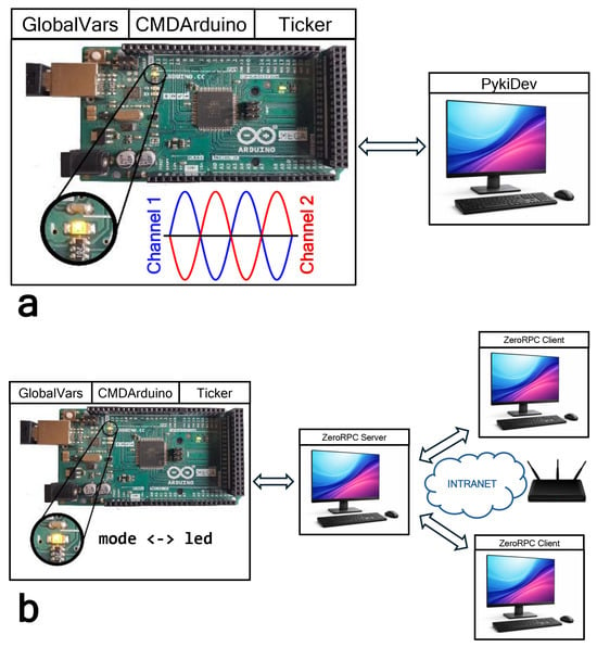
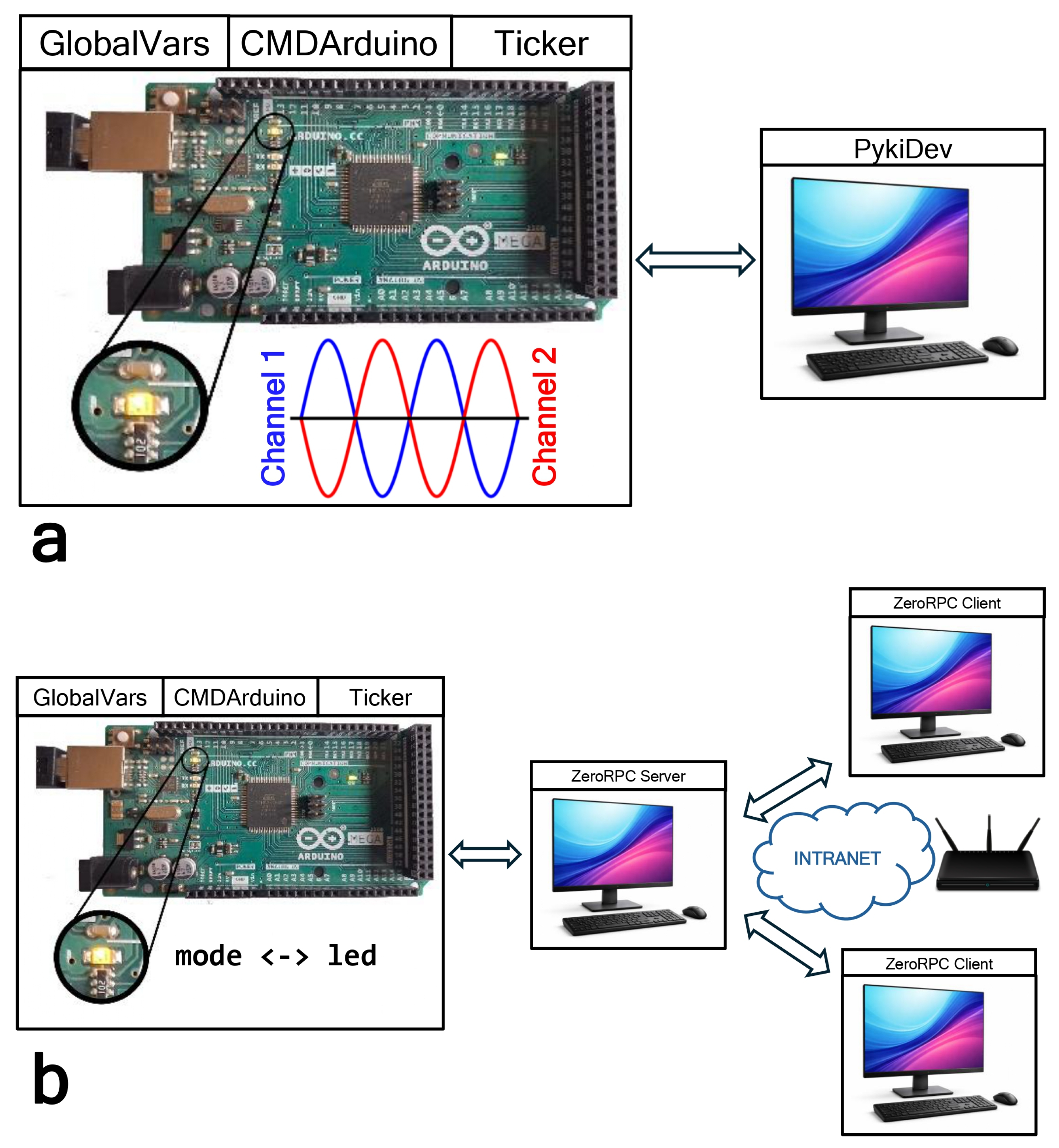
The demonstration project can be operated in two configurations. In the centralized configuration, the Python application communicates directly with the microcontroller through the PykiDev driver. In the distributed configuration, the same device is exposed through a ZeroRPC microserver, allowing remote access over a local network while preserving the same high-level Python interface. The two configurations are illustrated in Figure 1. All command interpreter functions are accessible from the PC through a standard serial terminal, the Pykiba driver, or the higher-level PykiDev interface.
Figure 1.
Conceptual diagram of the SMILE architecture for (a) centralized and (b) distributed laboratory networks.
The correspondence between serial commands and Python calls is illustrated in Table 1.
Table 1.
Examples of automatic mapping between serial commands and Python method calls.
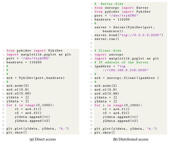
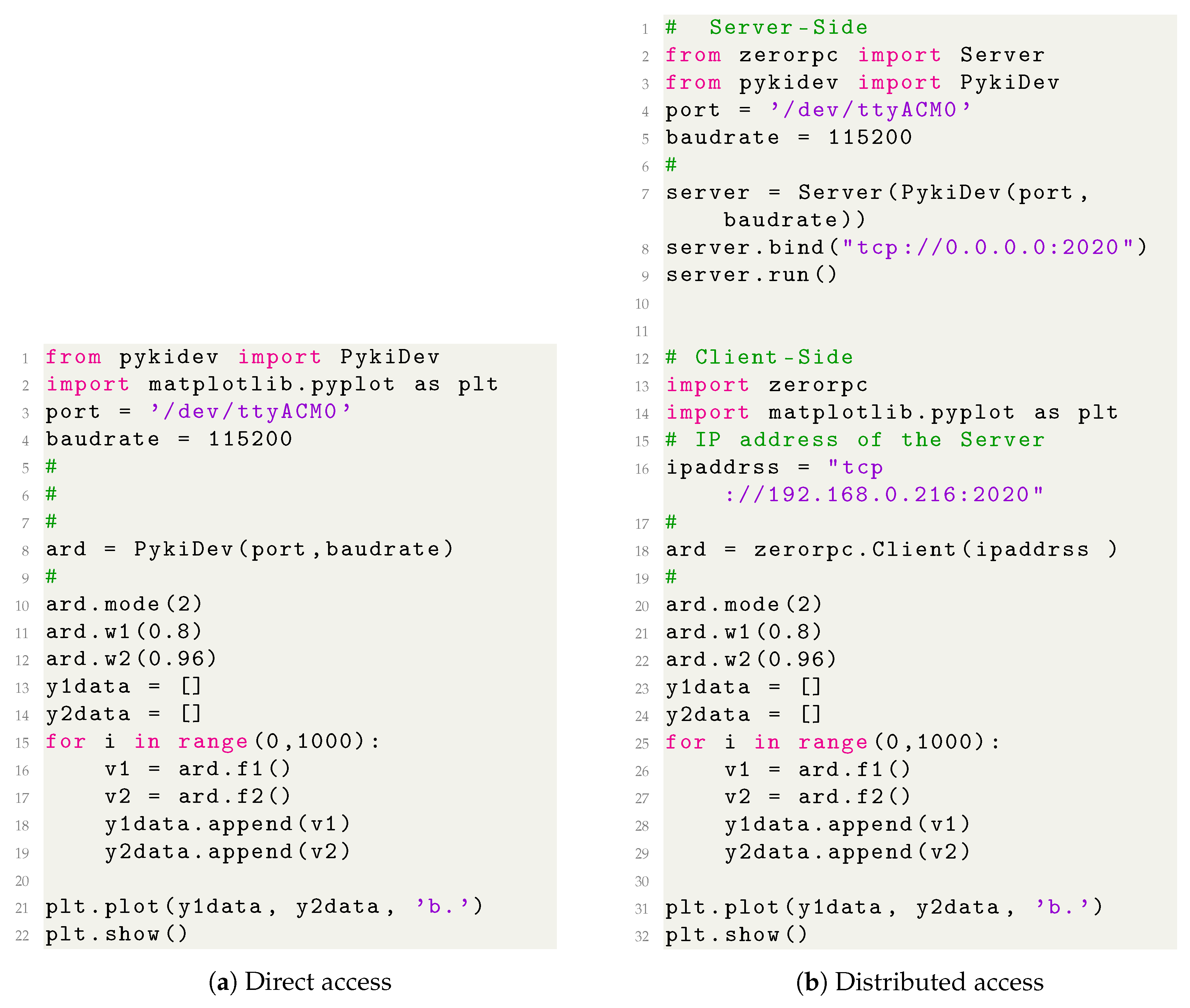
The core Python script presented in Figure 2 demonstrates the main architectural idea of SMILE. Although the communication mechanisms differ, the application code remains almost identical. Once the connection object has been created, the same high-level method calls are used for parameter control and data acquisition in both the centralized and distributed configurations.
Figure 2.
Comparison between direct PykiDev access and ZeroRPC client access. After the connection object is created, the same high-level Python commands are used in both cases.
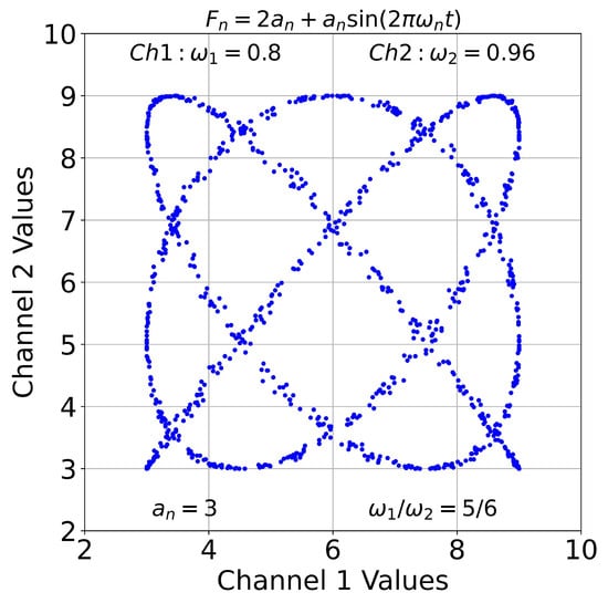
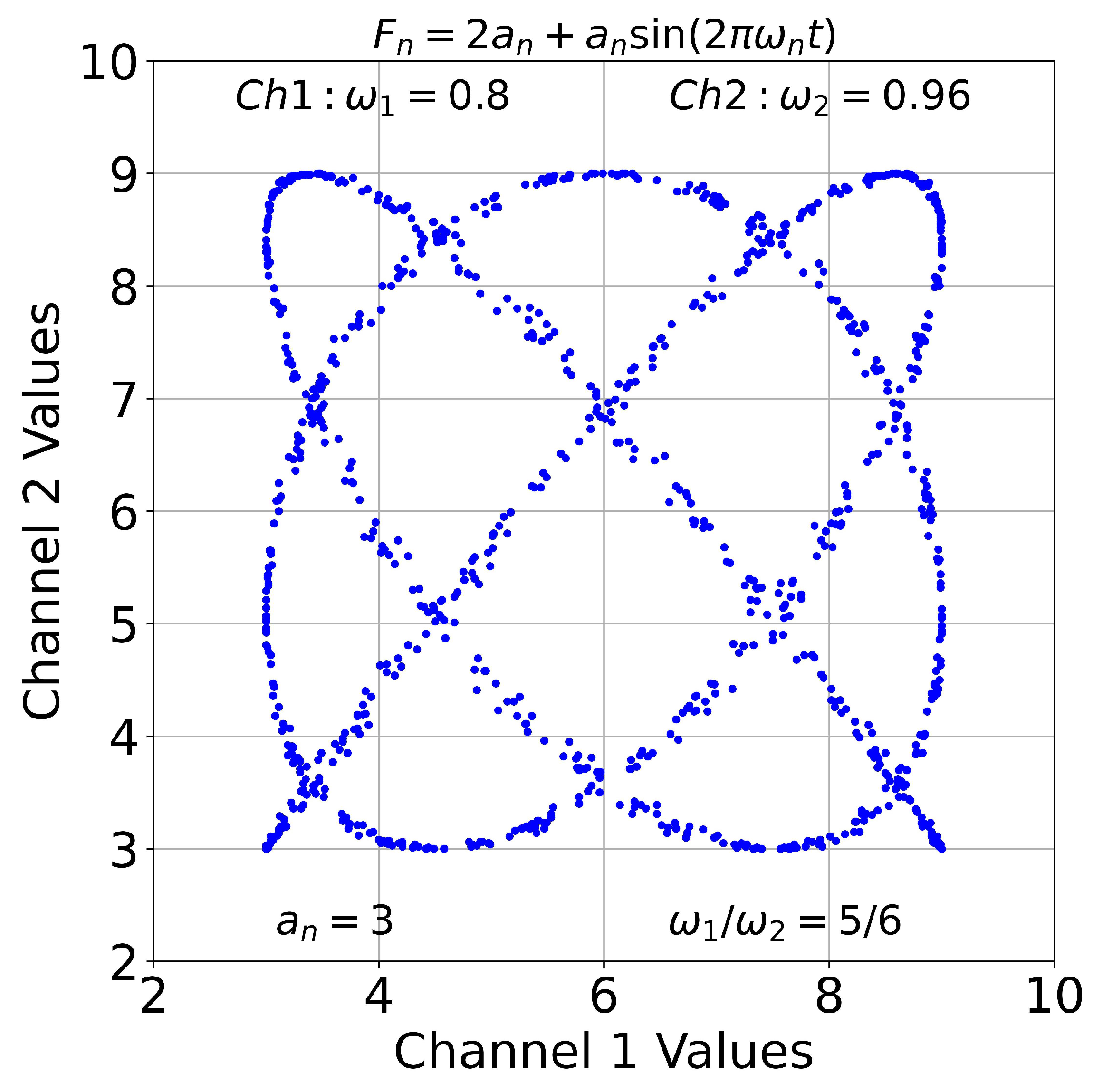
The Python script example shown in Figure 2 acquires samples from the two generated channels and plots them against each other. A typical result is a Lissajous figure, which provides a simple visual verification that the generated signals can be acquired, transmitted, and visualized identically in both operating modes. A representative example is shown in Figure 3. At much higher frequencies the wave-forms are distorted due to data acquisition rate limitations.
Figure 3.
Representative Lissajous figure generated from the two synthetic channels produced by the demonstration firmware.
4. Experimental Methodology
The experimental evaluation of SMILE was based on the demonstration firmware described in the previous section and consisted of two complementary benchmarks. The first benchmark assessed the maximum achievable acquisition rates using synthetic sinusoidal signals generated by the firmware. The second benchmark quantified communication latency under several deployment scenarios representative of centralized and distributed operation.
4.1. Acquisition-Rate Benchmark
The experiments were performed on a Dell Latitude laptop equipped with an Intel Core i5-6300U processor running at 2.40 GHz, Intel HD Graphics 520, and 8 GB RAM, operating under MX Linux 21.3. All measurements were performed using an original Arduino Mega 2560 microcontroller board communicating at a serial baud rate of 115,200 bps.
The benchmark script continuously acquired blocks of 40 samples at the maximum achievable rate.
For each communication configuration, a critical frequency, , was defined as the frequency at which exactly two periods of the sinusoidal signal fit within a buffer of 40 samples, corresponding to 20 samples per period (10 samples per half-period). Two communication configurations were investigated: direct access through the imported PykiDev driver and access through a local ZeroRPC server running on the same computer.
If the effective acquisition rate is R samples/s, the 40-sample buffer spans seconds. Since the critical frequency is defined as the frequency for which two complete periods occupy the entire buffer, , where . Therefore,
Above this frequency, the acquisition rate becomes insufficient for accurate waveform reconstruction, resulting in waveform distortion that may, at some frequencies, resemble another harmonic signal. The same definition was applied to both acquisition modes: fixed-buffer acquisition and sliding-buffer acquisition with animated visualization.
The theoretical upper limit imposed by the serial communication channel can be estimated from the selected baud rate of 115,200 bit/s. Considering the standard serial format (1 start bit, 8 data bits, and 1 stop bit), each transmitted character requires 10 bits, corresponding to approximately 11,520 characters/s. In the benchmark, a typical transaction consists of a three-character command (f1\r) and an eight-character response (1.11\n\n), corresponding to approximately 11 transmitted characters per request–response cycle. This yields an upper limit of approximately 1047 complete transactions per second. Since the benchmark defines the critical sampling condition as 20 samples per signal period (10 samples per half-period), the corresponding theoretical upper frequency limit imposed by the serial channel is approximately Hz.
This value closely matches the practical limit of the demonstration signal generator. With an update period of 1 ms, a 50 Hz sinusoid is represented by approximately 20 samples per period (10 samples per half-period), corresponding to the waveform resolution used throughout this study. The waveform-generation routine requires approximately 800 µs to execute, leaving only a limited timing margin for communication and other firmware activities. Consequently, the generator operates close to both the computational limit of the firmware and the communication limit imposed by the selected serial baud rate.
4.2. Communication Latency Benchmark
To characterize the latency of the SMILE distributed architecture, a dedicated communication benchmark was performed using three computers connected through a local network. The Arduino device and the ZeroRPC server were hosted on the Linux workstation described above. Two additional office-class computers running Windows 11, with identical hardware and software configurations, were used as remote clients.
Communication latency was measured by repeatedly writing and reading back a dummy parameter that performed no computation on the microcontroller. The selected parameter was intentionally chosen to minimize firmware-side processing and thereby isolate the communication overhead. To verify communication integrity, the transmitted values were sequentially incremented from 0 to 10,000, and each returned value was compared with the corresponding transmitted value. Any mismatch was counted as a communication error. As a result, the measured delay primarily reflects the combined effects of serial communication, ZeroRPC processing, network transport, and host-side software execution. Each benchmark consisted of 10,000 consecutive write–read transactions.
The investigated scenarios included: (A) direct access using PykiDev on the Linux workstation; (B) a ZeroRPC client running locally on the same Linux machine as the server; (C) remote access from a Windows 11 client; and (D–F) latency measurements obtained simultaneously from three concurrent clients, namely the local Linux client and two remote Windows 11 clients.
5. Results and Discussion
The two experiments address different aspects of system performance. Table 2 characterizes the maximum acquisition rates achievable during realistic operation, including data handling and visualization. In contrast, the communication benchmark presented in Table 3 isolates the request–response mechanism and quantifies the latency introduced by serial communication, ZeroRPC processing, and network transport.
Table 2.
Maximum achievable critical frequencies measured for the two software architectures and acquisition scenarios. Values are reported as mean ± standard deviation from five independent measurements.
Table 3.
Communication latency measured for different deployment scenarios.
5.1. Acquisition Performance
Table 2 summarizes the maximum critical frequencies obtained from five independent measurements.
The experimentally observed acquisition rates are substantially lower than the theoretical limit imposed by the serial communication channel. Regardless of the exact distribution of the software overhead among the individual host-side components, the measured acquisition rates remain far below the theoretical communication limit. This suggests that the serial communication layer itself is unlikely to be the dominant limiting factor under the tested conditions. This interpretation is based on the observed performance gap and the communication-latency measurements; however, detailed profiling of the Python implementation was beyond the scope of the present work. In the communication-latency benchmark, the host application only verifies the correctness of the transmitted data, whereas the acquisition-rate benchmark additionally performs buffering, data management, and, in one configuration, real-time visualization. Therefore, the acquisition rates reported in Table 2 should be regarded as representative of a realistic laboratory workflow rather than a pure communication benchmark.
The slight difference observed in the animated visualization scenario ( Hz for direct communication and Hz for ZeroRPC) is comparable to the experimental variability and is affected by additional factors (does not entail that the ZeroRPC architecture outperforms the direct communication). In this configuration, the execution time is dominated by real-time graphical rendering and associated host-side processing, while the communication overhead represents only a minor fraction of the total acquisition cycle.
The large difference between the theoretical communication capacity and the experimentally observed acquisition rates suggests that replacing the human-readable ASCII protocol with a more compact binary protocol would provide only limited practical benefit. The communication overhead represents only a fraction of the total execution time, while the ASCII protocol substantially simplifies development, debugging, and interactive use. Therefore, optimization of the communication protocol alone is unlikely to produce a proportional increase in the overall system performance.
5.2. Communication Latency
Table 3 summarizes the communication latency measured for the investigated deployment scenarios.
The latency measurements demonstrate the additional overhead introduced by the distributed architecture. Direct access through PykiDev achieved an average round-trip latency of approximately 7 ms. Introducing the ZeroRPC layer increased the latency to approximately 11 ms for local communication on the same workstation, while remote network access from Windows clients increased the latency to approximately 16 ms. Simultaneous operation of three clients further increased the average latency to approximately 19–22 ms.
No failed transactions were observed in any of the 10,000 communication cycles performed by each client. In the three-client benchmark, all clients were started independently and executed their request–response loops concurrently while sharing the same server-side variable. Each client repeatedly wrote a test value, immediately read it back, and verified that the returned value matched the transmitted one. Because the clients were started manually and executed asynchronously on different computers, their request sequences were naturally offset in time, making simultaneous transmission of identical test values unlikely during the benchmark. Furthermore, the server processes requests sequentially, so concurrent client requests are serialized internally before accessing the shared variable. Consequently, no application-level communication errors or data corruption were observed during the benchmark.
The reliability mechanisms currently implemented in SMILE rely primarily on the timeout and recovery facilities provided by the underlying communication libraries. Serial communication through Pykiba and PykiDev uses the timeout functionality of the PySerial library, while ZeroRPC applies a configurable command-execution timeout. If a timeout condition occurs, the client receives an exception, whereas the server process remains operational and available for subsequent requests. As a result, communication failures are generally detected and reported to the client rather than causing a server-side lock-up. Although the present work does not constitute a formal long-term reliability study, no application-level communication failures were observed during the 10,000 request–response cycles included in the benchmark.
Occasional latency spikes exceeding 200 ms were observed on some Windows clients. These rare events are most likely caused by operating-system scheduling and network-stack behaviour rather than limitations of the SMILE architecture itself.
5.3. Discussion and Practical Limitations
The results indicate that the performance penalty introduced by the ZeroRPC layer remains moderate compared to direct PykiDev access, while providing the additional flexibility of distributed operation and network transparency.
The experimental results presented in Table 2 and Table 3 provide practical guidelines for the expected performance of SMILE under different deployment scenarios. However, no universal upper limit on system complexity or throughput is imposed by the proposed architecture, as the achievable performance strongly depends on the specific experimental design.
The scalability of SMILE is developed primarily at the architectural level. Additional instruments can be added as independent microservers, each exposing its own command interface through ZeroRPC. In this configuration, the workload is naturally distributed among multiple devices and host processes. The practical scaling limit depends on several factors, including the serial latency of individual instruments, network latency, host-computer resources, and the computational overhead associated with data processing and visualization. Consequently, system scalability is determined primarily by the characteristics of the experimental setup rather than by a fixed architectural limitation of SMILE itself.
The results should be interpreted in the context of the intended application domain of SMILE. Neither Linux nor Windows are real-time operating systems and therefore cannot guarantee deterministic execution timing. For this reason, time-critical tasks such as PID regulation, waveform generation, and high-rate data acquisition should preferably be implemented directly on the embedded device.
Within this architecture, the host computer acts primarily as a supervisory layer responsible for parameter configuration, data logging, visualization, and experiment orchestration. The measured communication latencies indicate that the communication subsystem provides sufficient performance for supervisory laboratory control. In practical applications, however, the sustainable parameter-update rate depends not only on the communication latency but also on application-specific processing, data logging, visualization, the number of connected instruments, and the overall experimental workflow. This performance is sufficient for a broad range of laboratory experiments involving slowly varying quantities whose characteristic time scales are on the order of seconds rather than milliseconds.
Therefore, rather than defining strict performance limits, the presented benchmarks allow users to estimate whether a particular experimental setup is compatible with the expected acquisition rates and communication delays.
6. Conclusions
SMILE extends the Arduino fast-prototyping paradigm by enabling the construction of distributed, network-based laboratory systems. Positioned between ad hoc Arduino-based setups and full-scale control frameworks such as TANGO and EPICS, it provides a smooth transition from standalone prototypes to network-accessible experiments without requiring a significant architectural shift.
The system follows the natural workflow of experimental instrumentation. An Arduino device can first be tested through a serial terminal interface, after which the same communication protocol is reused without modification by a Python driver and subsequently exposed as a ZeroRPC server. Through the automatic mapping of serial commands to Python functions, any modification or addition of a command immediately becomes available locally and remotely.
SMILE can be implemented on a wide range of Arduino-compatible platforms while retaining access to device-specific hardware features through either the Arduino abstraction layer or direct C/C++ programming. External instruments using interfaces such as GPIB, RS232/485, USB, or Ethernet can be integrated through lightweight adapter layers written in Python or Node.js, allowing heterogeneous devices to participate in the same distributed architecture.
Experimental evaluation demonstrated practical acquisition rates and communication latencies suitable for many laboratory applications. The proposed architecture supported simultaneous multi-client operation without application-level communication failures during 10,000 request–response cycles. Nevertheless, the flexibility of distributed systems comes with trade-offs, including limited access control and potential concurrency issues when multiple clients interact with the same experiment. These challenges can be mitigated through network isolation and appropriate deployment strategies.
By leveraging lightweight technologies such as Python, ZeroRPC, and low-cost microcontrollers, SMILE aims to provide an accessible entry point into distributed laboratory automation without sacrificing modularity and extensibility.
The realization of distributed laboratory architectures that could be implemented using lightweight technologies, without the complexity typically associated with large-scale frameworks, was very useful and ultimately inspired both the philosophy and the name of the project.
Author Contributions
Conceptualization, K.K.; methodology, K.K. and V.A.; software, K.K. and V.A.; validation, K.K. and V.A.; formal analysis, K.K.; investigation, K.K., V.A., L.K. and K.B.; resources, K.K. and K.B.; data curation, K.K. and V.A.; writing—original draft preparation, K.B. and K.K.; writing—review and editing, K.K.; visualization, V.A. and L.K.; supervision, K.K. and K.B.; project administration, K.B.; funding acquisition, K.K. and K.B. All authors have read and agreed to the published version of the manuscript.
Funding
This research was supported by Chip Centre of Competence Bulgaria C3BG, Project ID 101217573, under Digital Europe Program DIGITAL-Chips-2024-SG-CCC-1.
Data Availability Statement
The source code, examples, and supporting materials used in this work are openly available at https://github.com/kamenov69/SMILE (accessed on 4 May 2026) An archived version corresponding to the software release used in this study is available through Zenodo at https://doi.org/10.5281/zenodo.19853831.
Acknowledgments
K.B. acknowledges the financial support by Chip Centre of Competence Bulgaria C3BG, Project ID 101217573, under Digital Europe Program DIGITAL-Chips-2024-SG-CCC-1. Artificial intelligence tools, specifically ChatGPT 5.5 developed by OpenAI, were used during the preparation of this manuscript for language translation, text editing, LaTeX formatting, and the generation of selected code fragments. All AI-assisted outputs were reviewed, verified, and modified by the authors as necessary. The authors assume full responsibility for the final manuscript, including its accuracy, originality, and scientific conclusions.
Conflicts of Interest
The authors declare no conflicts of interest.
Abbreviations
The following abbreviations are used in this manuscript:
| SMILE | Scalable Modular Instrumentation for Laboratory Experiments |
| GUI | Graphical User Interface |
| IOC | Input/Output Controllers |
| RPC | Remote Procedure Call |
References
- Cardoso, L.G.; Gaspar, C.; Barbosa, J.V.; Alessio, F. Controlling DAQ electronics using a SCADA framework. In Proceedings of the 2016 IEEE-NPSS Real Time Conference (RT), Padua, Italy, 6–10 June 2016; pp. 1–4. [Google Scholar] [CrossRef] [Scilit]
- Daneels, A.; Salter, W. What is SCADA? In Proceedings of the 7th International Conference on Accelerator and Large Experimental Physics Control Systems, Trieste, Italy, 4–8 October 1999; pp. 339–343. [Google Scholar]
- White, G.; Shankar, M.; Cobb, T.; Dalesio, L.; Davidsaver, M.; Hartman, S.; Kasemir, K.U.; Pearson, M.; Vodopivec, K.; Hickin, D.; et al. The EPICS software framework moves from controls to physics. In Proceedings of the International Particle Accelerator Conference (10th), Melbourne, Australia, 19–24 May 2019. [Google Scholar] [CrossRef]
- Leone, D.; Carrubba, V.; Mazzaro, S.; Nobili, M.; Cucè, D.; Hamilton, D. EPICS application for ITER RH supervisory control system. Fusion Eng. Des. 2021, 169, 112429. [Google Scholar] [CrossRef] [Scilit]
- Dalesio, L.R.; Hill, J.O.; Kraimer, M.; Lewis, S.; Murray, D.; Hunt, S.; Watson, W.; Clausen, M.; Dalesio, J. The experimental physics and industrial control system architecture: Past, present, and future. Nucl. Instrum. Methods Phys. Res. Sect. A Accel. Spectrometers Detect. Assoc. Equip. 1994, 352, 179–184. [Google Scholar] [CrossRef] [Scilit]
- Götz, A.; Taurel, E.; Pons, J.; Verdier, P.; Chaize, J.; Meyer, J.; Poncet, F.; Heunen, G.; Götz, E.; Buteau, A. TANGO a CORBA based Control System. In Proceedings of the 9th International Conference on Accelerator and Large Experimental Physics Control Systems (ICALEPCS2003), Gyeongju, Republic of Korea, 13–17 October 2003; pp. 94–98. [Google Scholar]
- Chaize, J.M.; Meyer, J.; Pérez, M.; Götz, A.; Taurel, E.; Klotz, W. TANGO: An Object Oriented Control System Based on CORBA. In Proceedings of the International Conference on Accelerator and Large Experimental Physics Control Systems, Trieste, Italy, 4–8 October 1999. [Google Scholar]
- Meyer, J.; Claustre, L.; Petitdemange, S.; Svensson, O.; Götz, A.; Coutinho, T.; Klora, J.; Picca, F.; Ounsy, M.; Buteau, A. Tango for experiment control. In Proceedings of the PCaPAC 2012—9th International Workshop on Personal Computers and Particle Accelerator Controls, Kolkata, India, 4–7 December 2012; pp. 118–120. [Google Scholar]
- Coutinho, T.; Cuní, G.; Fernández-Carreiras, D.; Klora, J.; Pascual-Izarra, C.; Reszela, Z.; Suñé, R.; Homs, A.; Taurel, E.; Rey, V. SARDANA: The software for building SCADAS in Scientific Environments. In Proceedings of the 13th International Conference on Accelerator and Large Experimental Physics Control Systems, Grenoble, France, 10–14 October 2011. [Google Scholar]
- Pascual-Izarra, C.; Cuní, G.; Falcon-Torres, C.; Fernández-Carreiras, D.; Reszela, Z.; Rosanes, M. Taurus big & small: From particle accelerators to desktop labs. In Proceedings of the 16th International Conference on Accelerator and Large Experimental Physics Control Systems (ICALEPCS’17), Barcelona, Spain, 8–13 October 2017; pp. 166–169. [Google Scholar] [CrossRef]
- Badamasi, Y.A. The working principle of an Arduino. In Proceedings of the 2014 11th International Conference on Electronics, Computer and Computation (ICECCO), Abuja, Nigeria, 29 September–1 October 2014; pp. 1–4. [Google Scholar] [CrossRef] [Scilit]
- Babiuch, M.; Foltỳnek, P.; Smutnỳ, P. Using the ESP32 microcontroller for data processing. In Proceedings of the 2019 20th International Carpathian Control Conference (ICCC), Krakow-Wieliczka, Poland, 25–29 May 2019; pp. 1–6. [Google Scholar]
- Zhao, C.W.; Jegatheesan, J.; Loon, S.C. Exploring iot application using raspberry pi. Int. J. Comput. Netw. Appl. 2015, 2, 27–34. [Google Scholar]
- Bell, C. MicroPython Hardware. In MicroPython for the Internet of Things: A Beginner’s Guide to Programming with Python on Microcontrollers; Apress: Berkeley, CA, USA, 2017; pp. 59–124. [Google Scholar] [CrossRef] [Scilit]
- Gartmann, R.; Krömer, O.; Weller, R.; Karcher, N.; Ardila-Perez, L.E.; Sander, O. Super heterodyne mixer front-end module for qubit readout and manipulation. In Proceedings of the 2024 IEEE International Conference on Quantum Computing and Engineering (QCE), Montreal, QC, Canada, 15–20 September 2024; Volume 2, pp. 567–568. [Google Scholar] [CrossRef] [Scilit]
- van Gend, C.; Lombaard, B.; Sickafoose, A.; Whittal, H. The South African Astronomical Observatory instrumentation software architecture and the SHOC instruments. In Proceedings of the Software and Cyberinfrastructure for Astronomy IV, Edinburgh, UK, 26 June–1 July 2016; International Society for Optics and Photonics: Bellingham, WA, USA; SPIE: Bellingham, WA, USA, 2016; Volume 9913, p. 99130R. [Google Scholar] [CrossRef] [Scilit]
- Wu, C.; Tobar, R.; Vinsen, K.; Wicenec, A.; Pallot, D.; Lao, B.; Wang, R.; An, T.; Boulton, M.; Cooper, I.; et al. DALiuGE: A graph execution framework for harnessing the astronomical data deluge. Astron. Comput. 2017, 20, 1–15. [Google Scholar] [CrossRef] [Scilit]
- Korcyl, G.; Bakalarek, M.; Moskal, P. Hardware-agnostic framework for general-purpose data acquisition systems. Measurement 2026, 257, 118528. [Google Scholar] [CrossRef] [Scilit]
- Yu, F.; Liu, K.; Zhou, H.; Li, M.; Kong, H.; Zhang, K.; Wang, X.; Wang, W.; Xu, Q.; Pan, Q.; et al. Finback: A web-based data collection system at SSRF biological macromolecular crystallography beamlines. Synchrotron Radiat. 2024, 31, 378–384. [Google Scholar] [CrossRef] [Scilit] [PubMed]
- Guijarro, M.; Beteva, A.; Coutinho, T.; Dominguez, M.C.; Guilloud, C.; Homs, A.; Meyer, J.; Michel, V.; Papillon, E.; Perez, M.; et al. Bliss-experiments control for esrf ebs beamlines. In Proceedings of the 16th International Conference on Accelerator and Large Experimental Physics Control Systems (ICALEPCS’17), Barcelona, Spain, 8–13 October 2017; pp. 1060–1066. [Google Scholar] [CrossRef]
- Pedersen, L.; Smith, T.; Lee, S.Y.; Cabrol, N. Planetary LakeLander—A Robotic Sentinel to Monitor Remote Lakes. J. Field Robot. 2015, 32, 860–879. [Google Scholar] [CrossRef] [Scilit]
- Bourlet, F.X. An Easy to Use, Intuitive, and Cross-Language RPC. 2026. Available online: https://www.zerorpc.com (accessed on 4 May 2026).
- Maxwell, J. EPICS for small-scale laboratories with Python soft IOCs. J. Instrum. 2026, 21, P03030. [Google Scholar] [CrossRef] [Scilit]
- Junkes, H. EPICS Also for Small and Medium Sized Experiments. In Proceedings of the 17th International Conference on Accelerator and Large Experimental Physics Control Systems (ICALEPCS’19), New York, NY, USA, 5–11 October 2019; pp. 1269–1272. [Google Scholar] [CrossRef]
- Randall, R.; Majumdar, A. PyOpticon: An Open-Source Python Package for Laboratory Control, Automation, and Visualization. Chem. Mater. 2025, 37, 4585–4592. [Google Scholar] [CrossRef] [Scilit]
- Christopher Wang CmdArduino. 2020. Available online: https://docs.arduino.cc/libraries/cmdarduino (accessed on 4 May 2026).
- Staub, S. Ticker, Arduino Library. 2021. Available online: https://github.com/sstaub/Ticker (accessed on 4 May 2026).
- Wang, C.A. CmdArduino. 2020. Available online: https://github.com/joshmarinacci/CmdArduino (accessed on 4 May 2026).
- Liechti, C. PySerial, Python Library. 2020. Available online: https://pyserial.readthedocs.io/en/latest/pyserial.html (accessed on 4 May 2026).
- Pieter Hintjens, M.S. ZeroMQ. 2026. Available online: https://zeromq.org (accessed on 4 May 2026).
- Furuhashi, S. MessagePack. 2026. Available online: https://msgpack.org (accessed on 4 May 2026).
- Granger, B.E.; Pérez, F. Jupyter: Thinking and storytelling with code and data. Comput. Sci. Eng. 2021, 23, 7–14. [Google Scholar] [CrossRef] [Scilit]
- Qualcomm. Arduino Mega 2560 Rev3. 2026. Available online: https://store.arduino.cc/products/arduino-mega-2560-rev3 (accessed on 4 May 2026).
- Labs, P. PlatformIO. 2026. Available online: https://platformio.org (accessed on 4 May 2026).

Disclaimer/Publisher’s Note: The statements, opinions and data contained in all publications are solely those of the individual author(s) and contributor(s) and not of MDPI and/or the editor(s). MDPI and/or the editor(s) disclaim responsibility for any injury to people or property resulting from any ideas, methods, instructions or products referred to in the content. |
© 2026 by the authors. Licensee MDPI, Basel, Switzerland. This article is an open access article distributed under the terms and conditions of the Creative Commons Attribution (CC BY) license.