


Abstract
This paper presents a semantic approach to support knowledge sharing in the assembly domain. Specifically, it focuses on capturing and sharing assembly design knowledge and on integrating the assembly design domain with the Assembly Process Planning (APP) domain through ontological modeling. A multilayered, heavyweight ontology framework, called the Product-Assembly Planning Ontology (PAPO), is proposed to integrate product assembly and APP. The ontology is based on product assembly features and uses these design features to provide the high-level semantic knowledge necessary to integrate product assembly design with APP. The paper also describes a detailed methodology for ontology design. Additionally, a rule-based engine is developed to reason about the available assembly design and APP knowledge and to infer new knowledge from them. Case study examples are included to illustrate the approach.
1. Introduction
In the Industry 4.0 era, assembly systems need to be highly adaptable to meet evolving production demands, including mass customization and personalized manufacturing, which require managing high product diversity, shorter product life cycles, and customer-specific requirements [1]. This can be achieved by promoting knowledge sharing between product design and manufacturing systems. The Evolvable Production Systems (EPS) paradigm, developed through European projects like EUPASS [2] and IDEAS [3], linking the product design and manufacturing system was a key aspect of EPS, offering significant benefits. Once a dynamic connection between detailed product design and potential production modules was established, the next step involved creating tools to analyze assembly processes from a product perspective, enabling the selection of appropriate equipment (for manufacturing). This article discusses some of the work performed during the development of such a tool, connecting production system development with product design phases.
Knowledge sharing between product design and manufacturing is essential; for example, as reported by True and Izzi [4], product design can account for up to 70% of a product’s lifecycle costs. However, capturing and sharing knowledge between product design and manufacturing remains a challenging task both on the domain and application levels. The challenge stems from the use of different conceptualizations to describe the same objects across domains, as well as heterogeneity among software applications. These challenges can be avoided by supporting semantic interoperability between product design and manufacturing. Semantic interoperability can be achieved when the meaning associated with captured information and knowledge can be shared across different domains/applications without any loss of information and knowledge [5].
Assembly is one of the most complicated tasks in a manufacturing environment [6]. Assembly involves combining components and requires a collaborative work environment across different domains to achieve an assembled or semi-assembled product. Product design and assembly process planning (APP) are critical domains for successful product realization. Both domains represent different perspectives on the same concepts and use different software applications, creating semantic interoperability issues. This research focuses on capturing and sharing assembly design knowledge to enhance the integration between the assembly design and assembly process planning (APP) domains. The research is based, in its first stage, on product features, utilizing product assembly design features to provide high-level assembly semantic knowledge necessary for integrating product assembly design with APP. This stage also includes using feature recognition techniques to extract assembly semantic knowledge from CAD software (SolidWorks © 2024). The second stage involves sharing the recognized assembly semantic knowledge through a layered ontology structure, which serves as a means of communication between assembly design and the APP.
Recently, ontologies and semantic web technologies have been widely applied to achieve semantic integration and to enhance semantic interoperability. An ontology attempts to define concepts, the mutual relations between them, and the constraints governing those relations. Several definitions have been addressed for an ontology [7,8]. One of the most comprehensive definitions is the one reported by [9]: “An ontology is a formal description of the entities within a given domain, the properties they possess, the relationships they participate in, the constraints they are subject to, and the patterns of behaviour they exhibit”. In this definition, formality is mentioned as one of the fundamental requirements for the ontology. Formality is highly related to interpretation by computers; the more formal an ontology is, the more interpretable by computers it becomes [10]. Ontologies are also classified according to the level of rigor and restrictions applied to the terminology conceptualized in the ontology into heavyweight and lightweight ontologies [10]. Heavyweight ontologies use axioms and constraints to restrict the meaning of terms and facilitate the deduction of new knowledge. Lightweight ontologies use textual definitions of concepts and terms, which can lead to ambiguities in defining their semantics [11]. Other classifications are based on the level of generality [12] and on the conceptualization structure [13]. Both classifications distinguish between upper ontologies (generic, top-level ontologies), domain ontologies, and application ontologies. Upper ontologies consist of generic, abstract, and high-level concepts that can be applied to a wide range of domains. Only a very general level of knowledge modeling can be done by using upper ontologies. An example of an upper ontology is a foundation ontology, which provides a knowledge base for more specialized ontologies, such as domain and application ontologies [14]. Domain ontologies consist of domain-specific concepts, whereas application ontologies capture the semantics of a specific application within a domain. The level of generality decreases from the upper to the domain and application ontologies.
In this paper, a formal heavyweight multi-layer ontology structure is proposed to provide a common semantic knowledge base that supports knowledge sharing across product design and assembly process planning (APP) at both the domain and application levels.
Figure 1 illustrates the proposed Product-Assembly Planning Ontology (PAPO) structure, where each layer shares a set of concepts that are specialized from the most generic to the most specialized levels. The foundation ontology is the first upper-layer ontology, which is designed to provide common concepts, such as product, feature, process, and resource, that are inherited by the domain ontology layer. The domain ontology layer represents the second level of the proposed structure, adding domain-specific concepts to a particular domain. The product design domain is further specialized into feature-based and assembly model domains. The feature-based model domain represents the product design’s geometrical knowledge (its form). Concepts such as Form Feature, Singular Feature, Pattern Feature, and Primitive Feature are specified in the product domain ontology’s feature-based model. The assembly model domain represents the behavior of the design unit during assembly.
Figure 1.
Ontology structure and knowledge sharing between product design and APP domains.
Concepts such as Assembly Feature, Mating Feature, Alignment Feature, and Joining Feature are specified in the product domain ontology’s assembly model. The APP domain is further specialized into the process and resource model domains. Concepts such as Assembly Process, Joining Process, Handling Process, and Screwing Process are specified in the process model of the APP domain ontology. In contrast, concepts such as Assembly Resource, Assembly Cell, Assembly Device, and Factory are specified in the resource model of the APP domain ontology. The third layer is the application ontology layer; in this paper, two application ontologies are included: The SolidWorks © 2024 application ontology and the assembly device application ontology. Concepts such as 3–D Feature, Mates, Reference Attributes, and Technology Entity are specified in the SolidWorks application ontology; on the other hand, Concepts such as Vacuum Gripper, Robot, and Finger Gripper are specified in the assembly device application ontology. Those ontologies capture semantics specific to each application. Two applications have been included: SolidWorks, a product design application, and an assembly robotic device (i.e., a high-speed assembly robot, Sony SRX series) as an APP application.
One of the main advantages of ontological modeling over other modeling types is its extensibility—the ability to expand as new knowledge emerges. The proposed multi-layer ontology structure effectively utilizes this advantage by facilitating expansion into new domains or applications. New domains and their related applications could be easily created and plugged into the existing multi-layer ontology structure.
Another main advantage of an ontology model is its reasoning capabilities. Ontology reasoning is based on the formal and logic-based specifications of the knowledge modeled in the ontology. Reasoning mechanisms will help answer cross-domain queries over ontology concepts and instances, infer new knowledge from existing knowledge, integrate and align heterogeneous knowledge resources, and provide decision support to designers and process engineers. In our proposed ontology structure, reasoning mechanisms are used to integrate domain and application ontologies, to infer and query new knowledge, and to design a rule-based decision engine that provides an automated, bidirectional link between assembly design and APP. More specifically, reasoning is used to extract implicit CAD assembly knowledge from the explicit knowledge provided by CAD software. Consequently, this will support the enrichment of recognized CAD assembly semantic knowledge and help determine the required processes and resources in the APP domain. Figure 2 illustrates the architecture for integrating assembly design knowledge and the APP system.
Figure 2.
The architecture of the assembly design knowledge and APP integration system.
In this paper, assembly design and APP knowledge, represented in the ontology structure, are formalized in OWL (Ontology Web Language) [15], a semantic ontology representation language developed by the World Wide Web Consortium [16]. The rule-based decision engine is developed using SWRL (Semantic Web Rule Language) [17], a rule language based on OWL, and Drools [18], a rule engine for the Java platform.
2. Background Literature: Product Design—APP Integration
There are many frameworks proposed for utilizing ontology in manufacturing-related domains such as product design, manufacturing, maintenance, assembly design, process planning, and APP. In this section, representative literature on applying ontologies to integrate product design and manufacturing is reviewed, specifically integrating product assembly design knowledge with APP.
Product features have served as the basis for most integration frameworks between product design and manufacturing. A helpful understanding of a feature is provided by the definition in Wierda [19]: “a feature is a partial form or a product characteristic that is considered as a unit, and that has a semantic meaning in design, process planning, manufacture, cost estimation, or other engineering discipline”. The importance of features as a bridge between product design and manufacturing has been extensively addressed in the published literature [20,21]. Assembly feature-based design [22] has been considered an extension of feature-based design for linking assembly design and APP. Van Holland [23] utilized assembly features in process planning by defining them as “features with significance for assembly processes”. The same author introduced more specific assembly features from a process perspective: connection features “such as final position, insertion path/point, tolerances” and handling features “characteristics that give the locations on an assembly component that a gripper can safely handle during assembly!” The assembly feature integration approach has been further extended by deriving object-oriented representations of assembly features [24] and their semantics [25]. A new integration approach based on assembly feature semantics is known as the Assembly Semantic Model [26]. This approach is primarily used to model assembly design knowledge and to provide sufficient information about the relationships between connected components/parts and the precedence constraints between connections. Since the efficiency of APP depends heavily on how the assembly design is modeled, this approach is considered a critical stage in integrating assembly design with APP.
In the published literature, some ontology-based integration approaches focus on capturing product design details, while others focus on manufacturing details. A few approaches try to balance the captured details between manufacturing and product design. Some other approaches try to integrate assembly design and assembly process planning.
On the manufacturing side, the Manufacturing Semantic Ontology (MASON) is proposed by [27] to support the capture and sharing of manufacturing knowledge. Manufacturing knowledge is captured through three main concepts: entities, operations, and resources. Entities represent both geometrical and non-geometrical knowledge (e.g., materials and costs). Operations represent manufacturing processes (e.g., machining and logistics). Resources represent both manufacturing and other resources (e.g., human resources). A machining ontology is proposed by [28] to represent knowledge in the manufacturing domain. This machining ontology includes geometrical knowledge (form features), machining processes, and machining resources. A metadata-based manufacturing resource ontology for the standardized semantic description of manufacturing resources (MRs) in cloud manufacturing (CMfg) systems is introduced by [29]. The ultimate purpose of the proposed ontology is to facilitate integration, sharing, and reasoning between distributed, autonomous, and heterogeneous MRs in CMfg systems. The proposed framework consists of a manufacturing resource domain ontology (MR_Onto) that semantically represents MRs in a structured manner using six main concepts: MResources, CServices, Owners, Knowledge, Transaction, and Status. MR_Meta, a metadata model for manufacturing resources, is also proposed to provide a formal description of resource attributes. To realize the transformation between MR_Onto and MR_Meta in the proposed framework, metadata-ontology mapping rules are also defined. A modular ontology for manufacturing systems based on the ISA-95 standard [30] (a multi-level framework developed by the International Society of Automation (ISA) for defining manufacturing systems in a hierarchical structure to enhance interoperability and knowledge sharing across these levels), extended with Semantic Web Rule Language (SWRL) rules to enhance knowledge representation and reasoning (KR&R), is proposed by [31]. The proposed work provides a standardized, modular, extendable, and reusable framework for describing manufacturing systems in accordance with the ISA-95 standard. The modular framework consists of sub-ontologies: Hierarchy ontology (representing level one and two of the ISA-95 standard, this ontology defines hierarchy models, object models, and attributes), OperationType ontology (represents level three and four of the ISA-95 standard, this ontology focuses on production management operations, including scheduling, resource dispatching, execution management, and recording operational data), and Resource ontology (represents resources as entities and providing capabilities for enterprise activities and business processes; this ontology serves as an intermediary level between the hierarchy and operation type ontologies and works as an intra- and inter-information exchange layer). These sub-ontologies are imported into a unified Enterprise Control Ontology (ECO), which serves as the framework’s unified ontology. Šormaz and Sarkar [32] introduced an upper-level ontology to address challenges in manufacturing process planning (MPP) in distributed and cloud-based manufacturing environments. These environments require flexible, dynamic process plans because of decentralized resources and varying shop-floor conditions. A semantic structure for manufacturing process planning is proposed that models three fundamental constraints: variety, time, and aggregation. It aims to integrate diverse manufacturing resources and dynamically generate process plans based on real-time shop-floor conditions and product design changes. OWL 2.0 is used to define the SIMPM structure, and SWRL rules match design specifications (e.g., geometry, tolerances) with the capabilities of manufacturing resources (processes, machines, tools) and infer new knowledge based on the defined logic rules. Wan et al. [33] proposed an ontology-based, multi-layer architecture to enhance the resource reconfiguration method for manufacturing cyber-physical systems (MCPS). The proposed method used an OWL ontology to define a knowledge base for manufacturing resources, enabling semantic modeling, knowledge sharing, reasoning, and resource allocation. The proposed architecture comprised four layers: a resource layer for shop-floor physical entities; a knowledge layer consisting of ontologies to model domain resources; an SWRL rule layer for a knowledge-base engine to support reasoning and decision-making; and a data layer where distributed databases store real–time data. The proposed architecture aims to support responsiveness, intelligence, and efficiency in MCPS and to be integrated with the Industry 4.0 environment, which presents challenges such as personalized customization, small-batch production, and efficient resource allocation. CDM-Core, a general manufacturing domain ontology, is presented by [34]. CDM-Core is being developed as a comprehensive manufacturing domain ontology for production and maintenance within the Horizon 2020 CREMA project. The ontology is built using the W3C standard OWL2-DL language [12]. It covers general manufacturing domains and is used in cases such as metal press maintenance and automotive exhaust production. The presented ontology supports the semantic description of process models, services, and sensor data for manufacturing use cases.
On the product design side, a product ontology to integrate production planning systems with product design applications is proposed by [35]. In this ontology, concepts are drawn from product data management [36] and enterprise integration [37] standards. The ontology includes concepts such as Product, Part, Component, and Assembly Component relationships to represent assembly areas within production planning and product design domains. Another product design ontology is proposed by [38] to integrate product design and Design for Manufacture (DFM). Their work also includes ontology, a development methodology for DFM. A product development ontology is proposed by [39] to support the reuse, integration, and sharing of design knowledge for decision-making during the product development process. The Manufacturing System Engineering (MSE) ontology was proposed by [40] to exchange knowledge across multidisciplinary design areas.
On both the product design and manufacturing sides, a product design and manufacturing process ontology is proposed by [41]. This ontology focuses on reusing knowledge from the Design Failure Mode and Effects Analysis (DFMEA) and Process Failure Mode and Effects Analysis (PFMEA) processes in manufacturing. An ontology to support knowledge sharing between the design and manufacturing domains is suggested by [42]. Their ontology enables the capture of manufacturing knowledge to support informed decision-making and knowledge sharing. A semantic manufacturing interoperability framework (SMIF) is proposed by [5] mainly to facilitate interoperability across product design and manufacturing domains. The SMIF consists of a multilayer ontological framework, in which the first layer provides a foundational ontology for modeling the domain. Domain ontologies for product design and manufacturing are provided by the domain ontology layer. The following two layers, Semantic Reconciliation and Semantic Interoperability, are dedicated to supporting interoperability and knowledge sharing across domain ontologies. Ref. [43] developed the ManuService ontology to represent a service-oriented product data model that facilitates make-to-individual production strategies in a cloud manufacturing environment. The proposed semantic framework seamlessly integrates concepts from international standards such as [44], which covers both manufacturing activities (e.g., machining, part handling, process validation) and non-manufacturing activities (e.g., inspection, assembly, packaging, and transit). It also integrates [45,46], both of which focus on data model representation and data exchange. This approach can enhance interoperability and enable cross-domain data exchange between product design and process planning. The proposed semantic model is based on a feature-based representation of product design knowledge, defining a semantic hierarchy composed of classes such as Project, Product, Item, Feature, Drawing, and Workplan. These classes provide a structured, comprehensive representation of product design for integration with manufacturing resources in the cloud environment. The ontology primarily focuses on machining features, including milling, turning, and hole-making features. OWL-DL with SWRL is used to formally construct the ontology and reason about the knowledge. A knowledge-based engineering (KBE) approach proposed by [47] integrates robotic manufacturing resources with user requirements and design perspectives. In this approach, ontological semantic models represent and infer relationships among functional requirements, including common (e.g., displacement, power supply) and specific (e.g., manufacturing tasks such as welding, cutting, engraving) functions of robotic manufacturing systems, and non-functional requirements, including Systems Properties (e.g., safety, cost, maintainability) and Workpiece Properties (e.g., cost, material, and dimensions). Two models are developed: the ontological Knowledge Model, which provides a structured semantic representation of user requirements, the architecture for robotic manufacturing systems, and their interconnections, and the Multi-Attribute Decision-Making (MADM) Model, which supports decision-making to select the most suitable robotic manufacturing architecture from the valid alternatives suggested by the ontological knowledge model. OWL is used to implement the proposed ontology, and SWRL and SQWRL (Semantic Query-Enhanced Web Rule Language) are used to query inferred results and retrieve valid component combinations. An OWL-based ontology to describe the capabilities of manufacturing resources, the Manufacturing Resource Capability Ontology (MaRCO), is addressed by [48] in a neutral, standardized, vendor-independent way. The proposed ontology aims to support the rapid, semi-automatic design, reconfiguration, and auto-configuration of production systems by automatically matching product requirements with resource capabilities represented in a vendor-neutral format, thereby enhancing interoperability and reusability and facilitating the adaptation of manufacturing systems to changing production demands. In the MaRCO ontology, product design is modeled by classes such as Product (which is further inherited by Part and Assembly subclasses). These classes describe product design specifications, which can then be matched to the required processes and capabilities through the Workplan class, which represents the sequence of process steps required to manufacture the product, and the ProcessStep class, which represents individual steps in the manufacturing process. These two classes serve as the link between the product model and the process taxonomy; product model specifications are imported into the process taxonomy via these classes. The other input to the process taxonomy is the capability model, which imports the manufacturing resource model. The MaRCO ontology is implemented in OWL, with reasoning enabled by the SPARQL Inferencing Notation (SPIN), which supports reasoning, inference, and automatic capability matchmaking.
Another multilayer framework, the Interoperable Manufacturing Knowledge System (IMKS), is proposed by [49] to provide seamless computer-based knowledge sharing between the departments of a manufacturing enterprise, specifically between product design and manufacturing. The IMKS supports interoperability by enabling the overcoming of semantic and syntactic differences during computer-based knowledge sharing through the use of foundation and domain ontologies. The IMKS is composed of four layers. The first layer provides a foundation ontology, later developed by [50], to establish common ground between the process specification language (PSL) ontology and the core ontology of product design and manufacturing concepts in the second layer. The third layer represents the domain ontologies (design and manufacture domains). The bottom layer in the proposed framework is the knowledge base layer. The knowledge base is built by using concepts from the domain ontologies in the upper layer. In the proposed approach, the knowledge base is populated by facts through a verification mediator. The verification mediator establishes integration between the product design and manufacturing domains by using queries to retrieve verified facts. The verified facts are sent to the manufacturing knowledge base for verification, ensuring that the manufacturing domain ontology raises no objections. The verification mediator then sends the verified facts back to the design knowledge base.
Ontology-based approaches for integrating product design and APP can be further categorized into two main approaches: the mereotopological design integration approach and the assembly feature-based design integration approach. The assembly design semantics in the first approach are based on mereotopological descriptions for assembly knowledge. In contrast, the second approach is based on geometric and topological descriptions of parts and on assembly knowledge provided by mates.
The first approach, as addressed in the literature, relies on Mereotopology (MT), a branch of logic that provides a qualitative formalization of two fundamental relationships between entities: parthood (i.e., one entity being part of another) and connection [51]. Design mereotopology (DMT) [51] is developed to identify and logically describe regions within geometrical entities and the interrelations between regions within a product. Ontological axioms have been used to restrict DMT to describe only regions of interest in the product design model. In this sense, DMT has been utilized in ontology-based assembly design modeling. A methodology developed by [52] to represent and differentiate assembly joint information in a collaborative product design environment based on a formal mereotopological ontology. In this ontology, assembly joining constraints are explicitly represented using SWRL rules and OWL triples derived from mereotopological definitions. The main contribution of [52] is the development of semantic definitions (e.g., for machine interpretation) for a theoretical mereotopological foundation of the assembly design. A novel approach has been proposed by [53] called PRONOIA (PROduct relatioNships description based On mereotopologIcAl theory) for defining product relationships based on mereotopological theory. This approach uses product relationships described by mereotopological primitives and Assembly Sequence Planning (ASP) to integrate assembly modeling and planning. The final integration stage is implemented using an OWL-DL (Web Ontology Language Description Logic) ontology and SWRL. A hierarchical multi-layer assembly knowledge representation framework (HAKF) and a microdevice assembly ontology (MA-Onto) are proposed by [54] to improve the efficiency and accuracy of microdevice assembly process planning. In their proposed framework, the authors used mereotopology to represent spatial relationships and part-whole relations in assembly knowledge. Spatial relationships between assembly objects have been described in terms of relative direction (spatial direction), proximity (spatial distance), and part–whole relationships between assembly features (spatial topology). The final integration stage is implemented by using OWL-DL ontology and SWRL. Web Ontology Language Description Logic (OWL—DL) is very descriptive in representing mereotopological Primitives.
The second ontology-based approach to support semantic integration between assembly design and APP, based on assembly features, has been adopted by several researchers. An ontology for modeling assembly processes is proposed by [55]. This ontology enables reasoning and querying of assembly knowledge using OWL and SWRL rules. An equipment ontology is proposed by [56] to support reconfigurability in manufacturing/assembly systems by facilitating decision-making for selecting assembly equipment. An ontology to capture product and process-related assembly knowledge and to integrate product design and assembly simulation is proposed by [57]. An assembly design ontology is proposed by [58] to provide a formal description of assembly design knowledge. The primary focus of that ontology was the assembly joint formalism, with a welding joint example provided. An assembly design ontology is proposed by [59] to capture assembly design knowledge for supporting the product development process. This ontology supports inferences and queries but lacks reasoning capability. Fiorentini et al. [60] proposed an ontology for representing assembly design. Their ontology is based on the Open Assembly Model (OAM) [61] and provides reasoning capabilities to support designers’ decisions. To model APP knowledge, Huang et al. [62] proposed an ontological model that covers key aspects of APP knowledge, including assembly requirements, spatial information, assembly operations, and assembly resources. Since no ontological formalism is reported for their work, it represents an incomplete attempt to model APP knowledge. A novel framework, an assembly reference ontology, that provides a common semantic base to support interoperability and knowledge sharing across the assembly design and assembly process planning domains, is proposed by [63]. Their work demonstrates the application of formal ontologies to knowledge sharing in assembly, focusing explicitly on concepts related to tolerance and fit, assembly features, assembly methods, and assembly resources. The ontological formalism used by [63] is the Knowledge Frame Language (KFL)which is based on Common Logic (CL) [64]. According to the authors, CL is more expressive than OWL [15] and better at representing the semantics of complex manufacturing concepts and relationships. Saha et al. [65] developed an ontology framework to support interoperability within and across welding standards. The Core Domain Ontology for Joining Processes (CDOJP) provides a modular, structured, formalized framework for consolidating and reconciling definitions and concepts across standards, ensuring interoperability and consistency. The proposed ontology aligns with major welding standards, including [66,67,68,69]. The ontology serves as a semantic knowledge base that explicitly captures the semantics of concepts and definitions, resolves contradictions within individual standards, and reconciles differences across them. The hierarchy ranges from general foundation concepts to domain and domain-specific concepts. The developed ontology links product design specifications to the required welding processes. It captures the relationships between product design elements, such as mating configurations, joint types, material properties, and the selection of appropriate welding processes. The ontology is more closely related to welding processes and the governing standards than to detailed design specifications. Design specifications are modeled as generic concepts that can be expanded. The CDOJP is formalized using OWL, and SWRL is used to define complex rules and enable advanced reasoning over different welding processes.
As a conclusion of this section, which provides a comprehensive review of ontology-based frameworks for integrating product design and manufacturing, with a focus on assembly design and assembly process planning (APP). Despite significant advances in developing ontologies to capture and integrate knowledge across these two important domains, several research gaps remain, which can be summarized as follows:
- Despite ontologies such as ManuService [43] and CDOJP [65], which are compatible and aligned with international standards, there is still no comprehensive universal framework that integrates diverse standards across the design and manufacturing domains. Some ontologies focus on product design standards, while others focus on manufacturing standards. This limits interoperability across standards in these two vital domains.
- Limited reasoning capabilities: Many of the proposed ontologies include rule-based engines to reason about available knowledge and infer new knowledge; despite this, most of them provide specific logic rules for specific incidents and processes, which limit the reasoning capabilities of these ontologies and, as a result, limit their ability to adapt to changes in manufacturing environments and domains, which is very critical for Industry 4.0 applications.
- Insufficient assembly design and APP modeling: Many ontologies provide concepts for assembly design and APP, but most lack formalism for all aspects of assembly design related to the required assembly processes. This is due to a lack of balanced, comprehensive formalism across all aspects of the design and the APP, including spatial relationships, tolerances, fit, and dynamic resource allocation. This limits the integration capabilities of the proposed ontologies.
- Improper modeling of assembly knowledge: Many proposed ontological frameworks lack modularity in modeling assembly design aspects and APP. Many of the proposed frameworks integrate geometrical, functional, and assembly data to model assembly design. This can complicate the reuse of assembly data in future product design projects, since the assembly data may remain valid across different geometries. It also complicates the extraction of assembly data from the design. On the other hand, there is a lack of modularity in modeling assembly processes and assembly resources, which are modeled as part of all manufacturing processes and resources. The complexity of assembly processes and resources necessitates separate models to formalize them in a rich, comprehensive way. The reusability of data depends heavily on how it is modeled. This improper modeling can affect efficient resource allocation, real-time data integration, and dynamic reconfiguration, especially in distributed environments such as cloud manufacturing. Therefore, the efficient use of ontologies in cloud manufacturing remains an open research gap that warrants further investigation.
- Lack of utilization of Mereotopology in modeling complex assemblies: Despite its use in assembly design modeling, there is a lack of its use in modeling complex assemblies, such as those with complex spatial relationships.
To address these gaps, our proposed ontology will use a balanced modular approach to separate feature-based data from assembly data on the product design side and to separate assembly processes and resources on the APP side. Modularity can enhance reusability and scalability in future design projects. The proposed ontological framework is based on product features to provide a comprehensive representation of all aspects of assembly design, with rich reasoning capabilities.
3. Research Methodology
The objective of this work is to enhance knowledge sharing across multiple design and assembly domains, particularly assembly design (feature-based and assembly design knowledge) and assembly process planning (process and resource knowledge). As detailed in the literature review, knowledge integration comprises two steps: knowledge capture and knowledge sharing. The proposed methodology, illustrated in Figure 3, is based on this. The methodology is mainly divided into five primary stages and follows the general ontology development methodologies reported in the literature [70,71,72,73].
Figure 3.
Ontology development and utilization methodology.
The proposed methodology includes the necessary steps of ontology specification, conceptualization, representation, formulation, and utilization. The first step aims to identify the key concepts and the related terminology in each layer of the ontology structure. This step involves determining the ontology’s purpose and scope. Based on this, the proposed ontology’s layer structure is designed, and the key concepts for each layer are identified. This step was briefly discussed in the introduction, where key concepts and terminology for the different layers of the proposed ontology are illustrated (Figure 1). Conceptualization by determining the tree concept structure (the sub-concepts for the key concepts defined in the first step) for different ontologies is included in the second step.
OWL lightweight representation of the informally defined concepts is performed in the third step. This step involves categorizing the classes, developing the class hierarchy of the ontologies using an ontology editor (Protégé), identifying properties for the class hierarchy, and mapping relations among classes.
The fourth step involves ontology formulation, which entails adding axioms, specifying class properties, and establishing relations between classes and properties. The Semantic Web Rule Language (SWRL) tab and the Drools rule engine in Protégé are used to express mathematical and logical relations among properties in the ontology, thereby enabling automatic reasoning.
The fifth and final stage of the proposed methodology includes three complementary validation approaches that, together, demonstrate the developed ontology’s logical consistency and practical utility. The first validation approach is logical consistency validation, conducted at two levels using the HermiT 1.4.3 description logic reasoner within Protégé 5.5.0. The first level is at the module level; each of the seven developed ontologies—GFO, FBM-DO, AM-DO, PM-DO, RM-DO, SW-AO, and AD-AO—was loaded independently and subjected to a full consistency check before integration. This step, which verifies logical consistency for each module, is critical for identifying structural errors that would otherwise propagate undetected into the integrated ontology. The second level of logical consistency validation is for the complete integrated PAPO, which must undergo a global logical consistency check. The second validation approach is the experimental quantitative validation through Case Study Instantiation. This approach demonstrates the ontology’s capacity to represent real assembly scenarios and to respond correctly to formal queries using the Query tab in Protégé and the Protocol and RDF Query Language (SPARQL) The third validation approach is the Rule-Based Knowledge Inference Validation. This approach assesses the ontology’s ability to infer new knowledge by executing SWRL rules with the Drools rule engine via the SWRLTab plugin in Protégé 5.5.0. The detailed ontology development methodology is presented in the next section.
4. Ontology Development
In the following subsections, the development of the multi-layer ontology structure (Figure 1) will be detailed further using the methodology introduced above. Each ontological layer is developed according to the methodology steps (1–4), while the overall multi-layer ontology structure is used in step 5.
The development of the multi-layer ontology structure PAPO procedure follows a bottom-up architecture, illustrated in Figure 4, starting with ontological knowledge from general foundational concepts and progressing to domain and application representations. The development proceeds from the foundation layer to the overall PAPO integrated ontology.
Figure 4.
PAPO development procedure.
In Figure 4, at the base of the architecture, the foundation and domain ontologies reside, implemented as a single merged ontology designated GFO-OWL. This is constructed by first developing the General Foundation Ontology (GFO) in OWL. Four domain-specific ontologies are then developed independently, each extending one of the GFO root concepts to introduce domain knowledge relevant to assembly planning: the Feature-Based Modeling Domain Ontology (FBM-DO, 13 classes), the Assembly Modeling Domain Ontology (AM-DO, 20 classes), the Process Modeling Domain Ontology (PM-DO, 11 classes), and the Resource Modeling Domain Ontology (RM-DO, 9 classes). These four domain ontologies are imported into GFO using the owl:imports directive, which causes the Protégé ontology editor to merge them automatically into a single unified GFO-OWL ontology. This merging ensures logical consistency, since all domain classes inherit the disjointness axioms and structural constraints of GFO without duplication. Above the foundation and domain ontologies, two application ontologies capture software-tool-specific and device-specific knowledge independently of the foundation. The SolidWorks Application Ontology (SW-AO, 81 classes) and the Assembly Device Application Ontology (AD-AO, 44 classes) are defined. Both SW-AO and AD-AO are developed as standalone ontologies with no owl:imports declarations, to ensure modularity and prevent the GFO and domain classes from appearing in their class panels during standalone editing. At the top of the architecture, the PAPO integrates all three sources of knowledge through three owl:imports statements for GFO-OWL, SW-AO, and AD-AO, respectively. A total of fifteen cross-layer rdfs:subClassOf axioms that establish the semantic connections between the application layer and the foundation-domain layer are declared in the PAPO. Furthermore, 22 SWRL inference rules are defined in PAPO to reason about the required assembly design and the required assembly process plans. The complete integrated PAPO encompasses 202 classes, 146 object properties, and 120 data properties, and can autonomously derive a recommended robotic assembly process plan directly from product design specifications through OWL reasoning and SWRL rule execution.
In the following subsections, the detailed development of the multi-layer ontology, PAPO, composed of three ontological layers, is introduced, with a set of ontologies for each layer. The following illustrates the development of these ontologies.
4.1. Ontology Development: Foundation Ontology Layer
The foundation ontology layer consists of the General Foundation Ontology (GFO). Foundation ontologies consist of generic, abstract, and high-level concepts that can be applied to a wide range of domains. Foundation ontologies also provide a knowledge base for more specialized ontologies. The GFO is the first upper-layer ontology, designed to provide common concepts—such as product, feature, process, and resource—that are subsequently inherited and expanded by the product design and APP domain ontologies provided by the second layer of ontologies. Figure 5 shows concept definitions and attributes for the GFO.
Figure 5.
Class hierarchy concepts and properties of the GFO.
Figure 5 shows the class hierarchy and the properties of different classes in GFO. An ontology consists of classes, properties between classes, and axioms that restrict these classes. A class defines a concept, while a property between classes indicates a relation holding between two instances of these classes. Based on the terms identified in the ontology, classes and properties among them are determined. The main GFO classes shown in Figure 5 are explained below.
In this research, the product class represents an assembled product composed of components and captures knowledge of its structure. The Product class has an attribute Component—the class property has-Component defined between the product class and the Component class. The Component class represents either a subassembly or a part. The Sub-Assembly class represents a collection of parts assembled together. A subassembly must contain at least two assembled parts. The Part class represents the basic structural design entity used to create a product. The Component class is connected to Sub-Assembly class or Part class via the is-Composed-of class property. The Sub-Assembly class is connected to the part class via the has-part class property. The class properties in the GFO reflect the inheritance relations between concepts and the relations between concepts and their attributes.
In this research, feature as a class represents the basic constituent design entity of a component, and is associated with Component class via the has-Feature class property. The feature class is further specialized into a single-piece part feature (Feature-for-Part) and an assembly feature (Feature-For-Assembly). The first represents the geometrical features of each part in the assembly design, while the second represents the assembly features that connect different parts. The Feature class is associated with Feature-for-Part and Feature-For-Assembly via the is-Feature class property. The Feature-for-Part class is expanded and inherited by the Feature-Based Model—Domain Ontology (FBM-DO); in contrast, the Feature-for-Assembly class is expanded and inherited by the Assembly Model—Domain Ontology (AM-DO) in the second domain ontology layer.
A process is considered as a generic concept that can be defined as “an ordered set of activities with a defined goal” [56]. In this research, the process concept is more closely related to the APP domain. Process, as a class, represents the activities required to convert the product design into a manufactured and/or assembled product. The Process class is connected to the Prdouct class via the Requires-Process property. Process is expanded and inherited by the Process Model—Domain Ontology (PM-DO).
A resource, as a generic concept, is defined by ISO 19115 [74] as “assets or means that fulfill a requirement”. Here, the Resource class represents the required means (equipment and tools) for manufacturing or assembling a product. The concept of resource is more closely related to the APP domain. The Resource class is connected to the Process class via the Uses-Resource class property. The resource is expanded and inherited by the Resource Model—Domain Ontology (RM-DO).
4.2. Ontology Development: Domain Ontology (DO) Layer
The DO layer consists of four domain ontologies (DO). Two of those are in the product design domain, namely the Feature-based Model (FBM-DO) and the Assembly Model (AM-DO), and the other two are in the APP domain, namely the Process Model (AM-DO) and the Resource Model (RM-DO). Each DO reuses concepts and properties from the FGO and defines more specified, expanded, and specialized concepts/properties for a particular domain. The FBM-DO is created to capture knowledge about a product’s form. Figure 6 illustrates the class hierarchy and properties between different classes in FBM-DO.
Figure 6.
Class hierarchy concepts and properties of the FBM-DO.
One definition of form feature is “Form features are specific configurations on surfaces, edges, or corners of a part, such as holes, slots, etc., that carry some engineering meaning” [75]. Form feature could be either in singular form or pattern form, where pattern feature (such as hole-pattern) is composed of identical singular form features (such as hole). A singular feature could be either in a primitive elementary form or a compound form, where the compound form is composed of two primitive elementary features in a parent/child relationship. Typical examples of compound form features are stepped holes and a pin with a head. A primitive elementary feature has three forms: volume (cylindrical, cubic, and other shape features), surface, and transition (such as chamfers and fillets).
In the FBM-DO, all kinds of form features have been specified as classes, with properties that connect them. The Pattern-Feature class has several attributes, such as shape and pitch (the distance between centers of successive singular features in a single row in the pattern), as follows:
- Marginal pitch (the distance between the singular feature center and the nearest surface edge);
- Diagonal pitch (the distance between the centers of singular features in adjacent rows of zig-zag singular features);
- Back pitch (the distance between the centers of two successive singular features in the pattern).
Each of the pattern feature parameters is characterized by a value and unit, which are expressed as data type properties, except for the shape parameter, which is characterized by only one data type property: has-Shape-Type.
The Assembly Model Domain Ontology (AM-DO) is designed for assembly modeling within the product design domain. Figure 7 shows the class hierarchy and properties of the AM-DO.
Figure 7.
Class hierarchy concepts and properties of the AM-DO.
AM-DO provides a basis for the design unit’s behavior during assembly. AM-DO includes three major classes: Assembly-Feature, Spatial-Relationship, and Degree-Of-Freedom. The Assembly-Feature class is composed of Handling-Feature, Alignment-Feature, Planar-Mating-Feature, and Joining-Feature subclasses. With these four subclasses, the Assembly-Feature class represents assembly design from an assembly modeling perspective (Alignment-Feature and Planar-Mating-Feature) and from an assembly process perspective (Handling-Feature and Joining-Feature). The Alignment-Feature and Planar-Mating-Feature subclasses represent mating features for cylindrical and planar surfaces, respectively, where a mating feature (or condition) is defined in [76] as “relationships that involve contact between parts, as well as relationships in which two parts do not have contact (e.g., clearance conditions!)”. The Handling feature class represents the parts’ geometrical characteristics needed to determine the required assembly transport resources, such as fixtures, feeders, and grippers.
More specialized forms of handling features are derived, such as gripping features represented by the Gripper-Feature subclass, which represents the geometrical characteristics needed to determine the required gripping resources. The Joining—Feature class, with its further specialization subclasses (Fitting-feature, Screwing-feature, etc.), represents the geometrical and non-geometrical knowledge (dimensional tolerance in the case of Fitting-Feature) needed to determine the required joining processes and resources to assemble a product. The Spatial-Relationship class expresses the relative positions of parts in an assembly in their final state, while the Degree-Of-Freedom class is used to describe the motion (translation and rotation) of parts during assembly.
The following two DOs are the Process Model (PM) and the Resource Model (RM) DOs of the APP domain. The PM-DO is illustrated in Figure 8, where the process class in GFO is expanded and inherited into Assembly-Process and Manufacturing-Process classes. The Assembly-Process class is further expanded into the Joining-Process and Handling-Process classes. The Joining-Process class is composed of subclasses representing different joining processes in APP, such as Welding and Screwing. The Handling-Process class is composed of Gripping, Feeding, and Fixturing subclasses.
Figure 8.
Class hierarchy concepts and properties of the PM-DO.
The RM-DO represents manufacturing and assembly resources in APP (Figure 9). The Assembly-Resource class is further decomposed into several subclasses, including Enterprise, Factory, Area, Line, Cell, Device-Combination, and Individual-Device. The Individual-Device subclass is further inherited by the Assembly Device Application Ontology (AD-AO) in the AO layer, which will be discussed in the next section.
Figure 9.
Class hierarchy concepts and properties of the RM-DO.
4.3. Ontology Development: Application Ontology Layer
The Application Ontology (AO) represents the lowest level of the proposed ontology structure and defines more specific, expanded, and specialized concepts/properties for a particular application. In this paper, two AOs are developed: the SolidWorks-Application Ontology (SW-AO) to model, capture, and share the semantics of the SolidWorks CAD software application, and the Assembly Device (AD-AO) to model, capture, and share the semantics of robotic assembly devices.
Many researchers try to develop an ontological model for CAD knowledge, either for enhancing interoperability between different CAD systems, supporting integration and exchange of knowledge in a collaborative engineering environment [77,78,79], or for enhancing interoperability between different CAD software systems and different applications such as Computer-Aided Manufacturing (CAM) [80]. A third category of researchers seeks to develop ontological model approaches to integrate CAD knowledge with shop-floor devices (such as robotic cells) in manufacturing/assembly systems [81]. The application layer in our proposed ontological structure is under this category, where a more comprehensive approach to developing an ontological model for SolidWorks CAD software and for robotic assembly devices is presented. The SolidWorks Application Ontology (SW-AO) illustrated in Figure 10 comprises six top-level classes that represent the significant components of the SolidWorks CAD software: Simulation, Sketch, Part File, B-rep Entity, Reference Attribute, and Assembly File. The Simulation and Sketch classes are not expanded here, since they are not mainly related to the purpose of integrating assembly design and APP. The other major classes are discussed briefly below.
Figure 10.
Class hierarchy concepts and properties of the SW-AO.
The Part-File class represents the SW-CAD part file, in which the feature tree and DimXpert tree are stored. The feature tree is represented by the Features class, a subclass of the Part-File class. The DimXpert tree is represented by the DimXpert-Manager, which is also a subclass of the Part-File class. The Features class includes all different kinds of features, such as Extrude, Fillet, Hole, and Revolve. The Features class represents the geometrical knowledge component of the CAD knowledge, while the DimXpert-Manager class represents the non-geometrical knowledge components, such as dimensions and tolerances, within the CAD knowledge. All different kinds of dimensions are represented under the Dimension subclass, while the two main types of tolerance, dimensional and geometrical, are represented under the Tolerance subclass.
The Features class is decomposed into the B-rep Entity class, which is further decomposed into the fundamental geometrical and topological entities: Geometry-Entity and Topology-Entity. Geometry-Entity has subclasses: Surface, Curve, and Point. The Surface class encompasses various types of surfaces used in geometric modelers; in this research, we are primarily limited to planar and cylindrical surfaces. Different types of cylindrical surfaces are listed under the Cylindrical-Surface subclass of Topology-Entity, which has the following subclasses: Edge, Shell, Loop, Face, and Co-edge.
The Reference-Attribute class defines various reference types as subclasses, including Existing-Part-Reference, Datum-Reference, and Coord-Sys-Reference, which can be used in a feature definition. The Assembly-File class includes the Mates subclass, which represents various mate relation types, including subclasses Coincident, Concentric, Parallel, Perpendicular, and Tangent.
The Assembly Device Application Ontology (AD-AO) (Figure 11) represents robotic assembly devices and comprises the top-level classes Robot, Tool Exchanger, Handling Tools, and Joining Tools. The Robot class encompasses various robots commonly used in robotic assembly devices, including the Scara-Robot, Mobile-Robot, and Hexapod-Robot subclasses. The Handling Tools class includes all tools used for handling and orienting parts during assembly. The Fixturing Tool, Gripping Tool, and Feeding Tool are subclasses of the Handling Tools Class. The Joining Tools class encompasses all tools used for joining parts during assembly, including subclasses such as Screwing Tool, Welding Tool, and Fitting Tool. Examples of specific tools within the Gripping Tool class include the Vacuum Gripper and the Finger Gripper. Properties for these different types of grippers will be defined as Attributes, such as gripping range, gripping power, and force, with associated values and units.
Figure 11.
Class hierarchy concepts and properties of the AD-AO.
Figure 5, Figure 6, Figure 7, Figure 8, Figure 9, Figure 10 and Figure 11 aim to provide a detailed picture of the ontology’s class hierarchy and the intra-relations (properties) between classes in each ontology in the framework. For all ontologies, all concepts are defined as classes. All classes inherit from the Thing subclass and are declared disjoint to prevent an individual from being an instance of more than one class, thereby avoiding multiple inheritance. Additionally, a reasoner is used to verify whether one class is a subclass of another within the complete ontology structure. Protégé 5.5.0, which was used to build this ontology, offers two reasoners, Pellet and HermiT 1.3.8. All 7 developed ontologies were tested with both reasoners, and no errors were found.
4.4. Ontology Development: PAPO Integrated Ontology
According to the ontology development plan in Figure 3, the PAPO integrated ontology is developed through three import stages. The first imports the four developed domain ontologies into the GFO to generate a single merged ontology designated GFO-OWL. The second and third import stages import the standalone application ontologies SW-AO and AD-AO, respectively. Defining the interrelationships among the ontologies within the PAPO framework is the second step in developing the PAPO. These relations are summarized in Table 1. Figure 12 illustrates the class hierarchy, property relationships across classes, and the ontologies in different layers of the PAPO multi-layer framework. Data properties are also illustrated.
Table 1.
Inter-relations among ontologies in the ontology structure.
Figure 12.
Class hierarchy concepts and properties of the PAPO.
4.5. Ontology Formalism and Utilization
The next step is to add restrictions on the defined OWL classes and properties. OWL classes are defined by their names, properties that can be applied to them, and the types of restrictions placed on those properties. Restrictions on properties are considered necessary for an instance of a class to be valid. OWL can only impose quantifier, cardinality, and hasValue restrictions on properties. The quantifier restrictions that can be used are the existential quantifier (∃), which states that a class must have some values from the restricted property, and the universal quantifier (∀), which states that the class must only have values from the restricted property. The cardinality restrictions are used to specify a minimum (≥), maximum (≤), or exact (=) cardinality, which indicates greater than, less than, or exactly a specific number of instances of a property. However, property restriction does not support variables. The number must be specified explicitly in the restriction definition. The hasValue restriction (∋) allows the restriction of properties that only have a specific individual or data value defined by the property.
The cardinality restriction type has been used extensively in the proposed ontology to restrict properties. For example, the Sub-Assembly class in GFO has been restricted in its property has-Part with cardinality of at least 2 (since any subassembly should at least contain two parts). Other examples of using cardinality in restricting properties in the GFO are listed below:
- has—Component with cardinality of at least 1 (any part is composed of at least a single component);
- is-Composed-of with cardinality of at least 1 (any component is composed of at least a single part or single sub-assembly);
- requires—Process with cardinality of at least 1 (to assemble a product, you need at least one process);
- uses-resource with cardinality of at least 1 (to perform any process, you need at least a single resource);
- has-Form-Feature with cardinality of at least 1 (any part is composed of at least a single form feature).
The restrictions mentioned above, which can define a class in OWL, are limited, as are the types of inferences that can be made with those restrictions. In OWL, it is convenient to describe intra-restrictions, which apply only to a class, such as cardinality restrictions. However, OWL cannot express inter-restrictions, which involve restrictions among or between classes, typically expressed as rule types. This is because OWL cannot describe property chaining [17]. To represent rule knowledge, the W3C (World Wide Web Consortium) developed the SWRL rule language 82, which is tightly integrated with OWL, because SWRL predicates can be OWL classes or properties. Additionally, SWRL enables users to write rules based on OWL concepts, offering more powerful reasoning capabilities than OWL alone. SWRL rules reason about OWL individuals, mainly in terms of OWL classes and properties. They are written as antecedent-consequent pairs, as shown in Figure 13.
Figure 13.
SWRL basic principles.
In the SWRL graph in Figure 13, the interaction between two OWL classes with two individuals connected via an OWL property results in an SWRL property that connects the two individuals. The new SWRL property is considered an inferred relation based on the existing OWL relations. Furthermore, the SWRL Built-Ins Library contains mathematical expressions, called Built-Ins, used to evaluate complex expressions in SWRL rules. The SWRLTab in Protégé allows users to write rules that reason about OWL individuals and infer new knowledge. The SWRLTab supports editing and executing SWRL rules. SWRL rules will be developed for case-study examples in the next section.
5. Case-Study Examples
5.1. Three-Button Panel Assembly
Based on the classes and properties modeled in Protégé-OWL, SWRL rules are developed to reason about the processes and resources required to assemble a product based on assembly design details. In this paper, a case study is used to quantitatively and experimentally verify the proposed ontology framework. The case-study model is a three-button panel assembly; its exploded view is shown in Figure 14. The case study consists of seven parts (the base part, the three buttons, the cover, and the screws). Each part has several specifications (dimensions and tolerances) that are populated with the proposed ontology framework.
Figure 14.
Exploded view of the three-button panel assembly.
The process plan for the case study is illustrated in Figure 15. For each process in the process plan, the related assembly design semantics are loaded into the ontology as individuals, and the rule engine gives options for the required processes and resources to assemble the case study. To develop SWRL rules that connect assembly design specifications with these processes, we first link assembly processes and resources to the assembly model specifications through the use of assembly features.
Figure 15.
Process plan for the three-button panel assembly and the related assembly design semantics.
Each assembly feature will be connected to the related assembly semantics on one side and to the required assembly processes and resources on the other side. The ontological relation models are developed to connect the B-rep modeled surfaces such that the features in SW-AO lead to assembly processes and resources via assembly features. All the features in the assembly design are decomposed into surfaces; in this case, these surfaces are either cylindrical or planar. Handling processes will be performed on the non-mating surfaces under the Part-File in the SW-AO, while joining processes will take place on Mating entities in the Assembly File in SW-AO. Handling processes (fixturing, feeding, and grasping) will take place mainly on the planar surfaces, with handling criteria specified in the process plan.
The handling criteria for the fixturing feature between two surfaces are based on non-mating relations between these two surfaces, as well as non-adjacent and perpendicular or parallel relations between them. Another important issue related to fixturing features is that it occurs only in the base part. Figure 16 illustrates the ontological map of fixturing features and their connections to fixturing processes and resources in the APP domain.
Figure 16.
APP perspective for fixturing feature.
Feeding features are based on the bottom planar surfaces for different parts in the assembly (except for the base part). A planar surface with a minimum Y-position is considered the feeding surface for different parts in the assembly.
Grasping features are mainly concerned with the parallel, non-adjacent, and non-mating surfaces for the finger gripping and with the upper top surfaces (surfaces with maximum Y coordinate) for vacuum gripping (for the middle button in the case-study example). Figure 17 illustrates the ontological map and related APP connections for the feeding and gripping features.
Figure 17.
APP perspectives for grasping and feeding features.
Joining processes such as fitting and screwing occur on cylindrical and concentric surface pairs. Specifically, a fitting assembly typically takes place between an internal simple cylindrical surface and an external simple cylindrical surface, forming a concentric connection. Similarly, a screwing process occurs between an internal threaded cylindrical surface and an external threaded cylindrical surface, which also have a concentric mating relation. These mating surfaces are connected via fitting or screwing features, which involve the respective processes. The relationships among fitting and screwing features, their associated processes, and resources are depicted in Figure 18.
Figure 18.
APP perspectives for fitting and screwing features.
A reasoning procedure for assembly handling is developed and implemented in SWRL rules, as in Table 2:
Table 2.
Reasoning procedure and SWRL rules for handling processes.
A fit is a dimensional relationship between cylindrical mating surfaces. According to the literature:
- A.
- Clearance fit: A hole (internal simple surface) and a shaft (external simple surface) have a clearance fit with each other if the minimum allowable dimension of a hole is larger than the maximum allowable dimension of a shaft. This can be expressed as:
Min. allowable dimension. Hole > Max. allowable dimension. Shaft
- B.
- Transition fit: A hole and a shaft have a transition fit with each other if the minimum allowable dimension of a hole is smaller than the maximum allowable dimension of a shaft, and the maximum allowable dimension of a hole is larger than the minimum allowable dimension of a shaft.
Min. allowable dimension. Hole < Max. allowable dimension. Shaft
Max. allowable dimension. Hole > mix. allowable dimension. Shaft
- C.
- Interference fit: A hole and a shaft have an interference fit with each other if the maximum allowable dimension of a hole is smaller than the minimum allowable dimension of a shaft.
Max. allowable dimension. Hole < mix. allowable dimension. Shaft
A reasoning procedure for assembly fit and assembly screwing is developed and implemented in SWRL rules in Table 3.
Table 3.
Reasoning procedure and SWRL definitions and rules for assembly joining processes (fitting and screwing).
Table 3 lists the SWRL rules required for reasoning about fitting and screwing processes. In this paper, the ISO tolerance standard BS 4500 [82] is used to specify tolerance quantities. Tolerance standards enable designers to specify tolerance quantities that depend on the dimensions of mating entities in the assembly (such as a hole and a shaft). The tolerance types for the hole start with the capital letter (such as H8, H7, etc.), while tolerance types for the shaft start with the small letter (such as f7, k6, p6, etc.). In this research, our approach is to decompose mating entities into their boundary surfaces. For the fitting mating entities, the hole is expressed as a simple internal cylindrical surface, while the shaft is expressed as a simple external cylindrical surface. For screwing mating entities, the hole is represented as a threaded internal cylindrical surface, while the screw is represented as a threaded external cylindrical surface. Both fitting and screwing entities are expressed in SWRL format at the beginning of the table. The first step in fitting reasoning is to capture the Max. Allowable Dimension and Min. Allowable Dimension according to rules 1 and 2. The third and fourth steps involve capturing the standard tolerance quantities in accordance with the ISO tolerance standard BS 4500 [82]. Table 3 shows only two of the standard tolerance quantities, which are captured based on the dimensions of the fitting mating entities (f7, H8) in steps 3 and 4. All other types of fits are captured in the same way, based on the mating-fitting entities’ dimensions. Fitting types are captured in the fifth step according to the definitions (1–4 in the bulleted list above). The next step (6) is to reason about the required fitting processes based on the fit types (whether a shrinking fitting process is used for the clearance and transition fit, or a pressing fitting process is used for the interference fit). The final step (7) for fitting reasoning involves reasoning about the required fitting resources based on the required fitting processes. Steps 8 to 10 are dedicated to reasoning about the screwing process and its resources. Step 8 is for determining the screwing feature between mating threaded entities. Based on this step-screwing process, the screwing process and screwing resource are determined in steps 9 and 10, respectively.
The first stage of quantitative experimental verification for the proposed ontology framework is to instantiate the ontology with case-study facts and then execute the SWRL rule, which requires a rule-based engine. In this paper, Drools is used to implement this. Drools supports the development of rule-based expert systems. It is considered a candidate for integration with the SWRL editor because it integrates seamlessly with Java, is well-documented, and has an extensive user base [18]. The interaction between OWL and the Drools rule-based engine is performed in the SWRLTab. The process involves transferring the OWL-captured knowledge and SWRL rules to Drools. After inference is performed using this knowledge and rules, the resulting Drools facts are transferred back to Protégé-OWL as new OWL knowledge [83]. The overall integration system is illustrated in Figure 19. The ontology structure represents both the assembly design model and the APP model. The modeling software, Protégé, encodes the assembly design and APP knowledge in OWL. Then, in the built-in SWRLTab, restrictions, constraints, and designer requirements are described in SWRL. After mapping the formalized assembly design, APP knowledge, and constraints onto the facts and rules in the Drools inference system, the engine performs the integration. It generates possible process plans and adaptation results for assembly design.
Figure 19.
The overall structure of the Assembly design- APP integration system.
The SWRL rule layer of PAPO comprises 22 rules organized into two groups: 12 handling-process rules (Table 2) and 10 joining-process rules (Table 3). Validation of these rules was conducted by rule Execution via SWRLTab Drools Engine, as illustrated in Figure 20.
Figure 20.
SWRLTab Drools Engine for three-button panel Assembly.
The Drools rule engine bridge was activated via the SWRLTab → Drools tab, and rules were executed by clicking Run Drools. Each rule’s consequent was expected to assert new property facts or class memberships for the case study individuals. For example, Rules T3-1 (rule 1 in Table 3) and T3-2 (rule 2 in Table 3) (Dimensional computation) computed the maximum and minimum allowable dimensions for all cylindrical surface individuals, as shown in Figure 21 and Figure 22.
Figure 21.
Maximum allowable dimension asserted facts to individual instances.
Figure 22.
Minimum allowable dimension asserted facts to individual instances.
Execution of the rules in Table 1 will examine all planar surfaces according to the criteria specified in these rules and assign suitable surfaces to different handling processes. Figure 23 illustrates the planar surfaces asserted facts to the individual instances.
Figure 23.
Planar surfaces asserted facts to the individual instances.
The second level of validation for the PAPO framework uses Description Logic (DL) and SPARQL queries. DL queries are executed in Protégé’s DL Query tab after starting the HermiT reasoner, with the Instances checkbox enabled. An example of DL query validation is the query about the Gripping-Tool; all instances related to gripping tools are generated, as illustrated in Figure 24.
Figure 24.
Gripping—Tool DL query instances.
Another DL query example is illustrated in Figure 25, a query about Handling-Process subclasses and instances. All different handling processes with instances related to the instant case study are available.
Figure 25.
Handling—Process DL query instances.
All DL queries returned the expected instances, demonstrating that the full three-layer class hierarchy, the cross-layer property chains, and all SWRL-inferred individual classifications were logically consistent and correctly integrated into the knowledge base.
Two SPARQL 1.1 queries are formulated and executed in the Protégé SPARQL Query tab to validate instance-level property chains (surface geometry—inferred process types—selected resources). This cannot be done with DL queries, which only verify class membership counts. SPARQL queries verify the existence and correctness of specific property assertion chains for named individuals. The first SPARQL query (Q1) traces the complete three-step inference chain for each of the six operation types—from geometric surface feature through process individual to robotic resource individual—confirming that no operation type was missing or duplicated in the generated assembly plan. The code for Q1 is illustrated in Figure 26, and a part of its output is illustrated in Figure 27.
Figure 26.
SPARQL query (Q1).
Figure 27.
SPARQL query (Q1) output.
Q2 (Figure 28) proved the dimensional reasoning embedded in rules T3 -1 and T3-2, verifying that the computed maximum shaft dimension (7.987 mm) is strictly less than the computed minimum hole dimension (8.0 mm) for all three button peg–hole pairs, correctly classifying each as a clearance fit per ISO standard [82] f7/H8. The output of Q2 is illustrated in Figure 29.
Figure 28.
SPARQL query (Q2).
Figure 29.
SPARQL query (Q2) output.
A complete validation procedure is performed on the PAPO framework. Structural consistency validation is performed for all developed ontologies and for the overall integrated PAPO using the HermiT reasoner, which performs a full consistency check over PAPO and all its imported modules. SWRL rule execution validation is performed using the Drools rule engine. Query validation is performed at two levels: at the instance level for classes using a DL query, and at the instance level for property chains using a SPARQL query. This full validation procedure confirms the structural, taxonomic, and instance-level correctness of the PAPO across all three ontology layers.
5.2. Pneumatic Cylinder Assembly (ISO 15552)
To demonstrate PAPO’s applicability in an industrial context, a standards-compliant pneumatic cylinder was selected as the second industrial case study. The chosen industrial case study is a double-acting cylinder (Figure 30) that complies with ISO 15552 [84], the international standard defining the basic, mounting, and accessory dimensions for the 1000 kPa (10 bar) series of cylinders with bores from 32 mm to 320 mm. This cylinder is representative of a widely deployed class of industrial actuators, such as the Festo DSBC-series—ISO 1552 [85], the Festo DNC series—ISO 15552 [86], and the Festo DSBG series—ISO 15552 [87]. The industrial case study is modeled as an 80 mm bore and a 100 mm stroke, with a shouldered piston-rod thread of M20 × 1.5 (KK) and a tie-rod pattern conforming to the ISO 15552 basic-dimension table [84].
Figure 30.
Pneumatic cylinder (ISO 15552).
The industrial case study, as illustrated in Figure 31, is composed of a well-defined set of parts (cap end, barrel, piston, piston rod, gland, tie rods, and counter nuts). It combines several distinct fit and joining types (clearance fits, threaded connections, and pre-installed elastic seals), and its geometry is fully governed by published dimensional standards. These properties make it an appropriate real-world benchmark for evaluating whether PAPO can infer a complete and physically valid assembly process plan directly from standardized product geometry.
Figure 31.
Pneumatic cylinder (ISO 15552) assembly parts.
The product specifications and standards for the Pneumatic cylinder (ISO 15552) assembly are listed in Table 4, and the parts list and their specifications are listed in Table 5.
Table 4.
General specifications of the pneumatic cylinder (ISO 15552) assembly.
Table 5.
Parts list of the pneumatic cylinder assembly.
The process plan for the pneumatic cylinder (ISO 15552) case study is shown in Figure 32. For each process in the plan, the corresponding assembly design semantics are loaded into the ontology as individuals, and the rule engine then provides options for the required processes and resources to assemble the case study. However, before instantiating the PAPO with the assembly design semantics of the pneumatic cylinder (ISO 15552) case study, the ontology classes and the SWRL inference rules must be extended to support the new case study.
Figure 32.
Process plan for the pneumatic cylinder (ISO 15552) assembly and the related assembly design semantics.
As illustrated in Figure 31, detailed in Table 5, and shown in the APP in Figure 32, P4 consists of the piston and its seals (the blue rings visible on the piston are rubber/elastomeric lip seals and O-rings) and is considered a preassembled subassembly. PAPO’s current rules cannot model the assembly of elastic components. Seals are assembled by stretching them over the piston and compressing them into the grooves—a fundamentally different joining process from fitting or screwing; this can be considered a future extension of PAPO’s rules. Some other rules of PAPO’s ontology will be extended to accommodate cylindrical surfaces for feeding and gripping processes. The required extensions for PAPO’s classes and SWRL engine rules are listed and explained in the following tables. Table 6 documents all additions to the PAPO OWL class hierarchy; Table 7 documents conditions that identify cylindrical part surfaces that require the new handling rules; and Table 8 documents the extended SWRL rule set required for cylindrical part handling for an ISO 15552 pneumatic cylinder. Six new rules extend Table 2 (reasoning procedure and SWRL rules for handling processes for three-button panel assembly) (T2-Rules 1–12). Rules 13–15 are implemented for the ISO 15552 pneumatic cylinder; Rules 16–18 are proposed as future work.
Table 6.
New OWL Classes and Data Properties—ISO 15552 pneumatic cylinder extension.
Table 7.
SWRL Definitions—Cylindrical Part Types—ISO 15552 pneumatic cylinder extension.
Table 8.
SWRL Inference Rules—Cylindrical Part Handling (T2-Rules 13–18)—ISO 15552 pneumatic cylinder extension.
Table 9 and Table 10 extend the SWRL definitions and inference rules from Table 3 to assembly-joining processes (fitting and screwing) required to assemble the ISO 15552 pneumatic cylinder. In Table 9, four new rows (5–8) are added to the SWRL Definitions in Table 3 to cover the M10 and M20 × 1.5 thread pairs present in the ISO 15552 pneumatic cylinder. In Table 10, three new sub-rules are added: Rule 3a extends tolerance capture to d11 at Ø22 mm; Rules 4a–4b extend H7 capture to the Ø22 mm and Ø80 mm diameter ranges; and Rules 8a–8b extend screwing feature detection to the M10 and M20 × 1.5 thread pairs. Rules 1–2, 5–7, and 9–10 from Table 3 are dimension- and thread-size-agnostic; they require no modification and cover all ISO 15552 pneumatic cylinder extensions for fitting and screwing operations without change.
Table 9.
SWRL definitions for assembly joining processes (fitting and screwing)—ISO 15552 pneumatic cylinder extension.
Table 10.
Reasoning procedure for assembly joining processes (fitting and screwing)—ISO 15552 pneumatic cylinder extension.
Quantitative experimental validation of the ISO 15552 pneumatic cylinder is conducted. The first stage of quantitative experimental verification for the proposed ontology framework is to instantiate the ontology with case-study facts and then execute the SWRL rules using the Drools rule-based engine. Rule-based knowledge inference was executed using all 25 SWRL rules—the 22 core rules validated in the first case study, extended by three second case study-specific rules (T2-Rule13 for cylindrical shaft gripping detection, and generalizations of T3-Rules 3a, 4a, and 4b to cover the four new ISO 286-1 [92] tolerance classes)—through the SWRLTab/Drools engine (Protegé 5.5.0, SWRLtab-plugin 2.0.11). The OWL + SWRL transfer stage exported 5073 axioms to the rule engine; Drools successfully inferred 2196 axioms in 273 ms, as shown in Figure 33.
Figure 33.
SWRLTab Drools Engine for ISO 15552 pneumatic cylinder.
The Drools rule engine bridge was activated via the SWRLTab → Drools tab, and rules were executed by clicking Run Drools. Each rule’s consequent was expected to assert new property facts or class memberships for the case study individuals. For example, Rules T3-1 (Rule 1 in Table 3) and T3-2 (Rule 2 in Table 3) (Dimensional computation), which are applied without any change for ISO 15552 pneumatic cylinders, computed the maximum and minimum allowable dimensions for all cylindrical surface individuals, as shown in Figure 34 and Figure 35.
Figure 34.
Maximum allowable dimension asserted facts to individual instances—ISO 15552 pneumatic cylinder.
Figure 35.
Minimum allowable dimension asserted facts to individual instances—ISO 15552 pneumatic cylinder.
Execution of the rules in Table 9 will examine all cylindrical surfaces according to the criteria specified in these rules and assign suitable surfaces to different joining processes. Figure 36 illustrates the cylindrical surfaces asserted facts to the individual instances.
Figure 36.
Cylindrical surfaces asserted facts to the individual instances—ISO 15552 pneumatic cylinder.
The second level of validation for the PAPO framework uses Description Logic (DL) and SPARQL queries. DL queries are executed in Protégé’s DL Query tab after starting the HermiT reasoner with the Instances checkbox enabled. An example of DL query validation is the query about handling processes; all instances related to handling processes are generated, as illustrated in Figure 37. The DL query returned the expected instances.
Figure 37.
Handling—Processes DL query instances—ISO 15552 pneumatic cylinder.
The populated ontology was validated using SPARQL queries (Q1 and Q2) executed against the HermiT-classified knowledge base in Protégé 5.5.0. SPARQL Q1 returned 21 distinct feature-to-tool rows covering all six operation categories: 2 fixturing chains from the cap-end perpendicular side faces, 6 feeding chains (one minimum-Y face per part P2–P7), 6 finger-gripping chains from the parallel non-adjacent non-mating planar surfaces of the gland, barrel, tie rods, and counter nuts, 2 vacuum-gripping chains from the flat top faces of the piston and piston rod, 3 clearance-fit chains from the three shaft individuals (piston rod, barrel OD, and tie rod shaft), and 2 screwing chains from the M20 × 1.5 and M10 threaded surface pairs—confirming that no operation type was missing or duplicated in the generated assembly plan. SPARQL Q1, tracing the complete three-layer feature → process → resource chain, returned an identical 21 rows, independently confirming the property assertion chains for every named surface individual. The code for Q1 is shown in Figure 38, and its output is shown in Figure 39.
Figure 38.
Q1 Code-ISO 15552 pneumatic cylinder.
Figure 39.
Q1 Output-ISO 15552 pneumatic cylinder.
SPARQL Q2 returned 10 clearance-fit rows across three geometrically distinct shaft–hole pairs. The code for Q1 is shown in Figure 40, and its output is shown in Figure 41.
Figure 40.
Q2 Code-ISO 15552 pneumatic cylinder.
Figure 41.
Q2 Output-ISO 15552 pneumatic cylinder.
Query validation is performed at two levels: at the instance level for classes using a DL query, and at the instance level for property chains using a SPARQL query. This full validation procedure confirms the structural, taxonomic, and instance-level correctness of the PAPO across all three ontology layers for ISO 15552 pneumatic cylinder.
6. Discussion
Table 11 presents the complete SWRL/Drools execution profiles for both case studies (CSs), measured directly from the Protégé 5.5.0 SWRLTab console output, alongside the corresponding inference-completeness results from the DL query and SPARQL verification reported in the previous section. Quantitatively, the ontology scales from 73 named individuals and 18 SWRL rules in CS1 (three-button panel) to 200 named individuals and 25 rules in CS2 (ISO 15552 pneumatic cylinder), a 2.7-fold increase in ABox size achieved with only four new TBox tolerance subclasses (Clearance-Fit-Tolerance-d11, -H7, -h6, -h8) and three new rule extensions (T2-Rule13 for cylindrical shaft gripping, and the generalization of the existing screwing-feature rule from a single M4 thread pair to the M10 and M20 × 1.5 threads specified by ISO 15552 Table 2). None of the 22 core SWRL rules validated in CS1 required modification to support CS3, indicating that the inference architecture generalizes across assembly domains without rule re-engineering. This scaling is reflected proportionally in every transfer-stage metric: total OWL axioms exported to the rule engine grew from 1599 (CS1) to 5073 (CS2), individual declarations from 105 to 136, and the feature-to-tool inference chains verified via SPARQL Query 1 for both case studies grew from 13 to 21 rows, while the shared TBox layers (191 classes, 134 object properties, 120 data properties) remained identical across both studies, confirming that the observed growth is attributable entirely to case-study-specific content rather than instability in the underlying ontology.
Table 11.
SWRL/Drools execution metrics: CS1 (Three-Button Panel) vs. CS2 (ISO 15552:2018 Pneumatic Cylinder).
The experimental validation reported in this paper is constrained by the capabilities of the available robotic assembly cell (i.e., a high-speed assembly robot, the Sony SRX series), which provides grasping (finger and vacuum gripping), feeding, fixturing, fitting, and screwing. Assembly processes requiring welding, adhesive bonding, or elastic-seal compression are outside this capability set and, accordingly, fall outside the scope of automatic SWRL inference in both case studies. This boundary is stated explicitly in the second case study (CS2). CS2’s piston-to-barrel insertion involves seal-compression interference that PAPO’s current T3-Rule 5b cannot compute from rigid-body geometry alone. This limitation is documented as an open limitation of the PAPO.
CS2 is chosen specifically because every process it requires—fixturing, feeding, finger and vacuum gripping, clearance fitting, and screwing—falls within the validated robotic cell’s capabilities, which is precisely what allows the SPARQL-verified inference chain to be read as evidence of deployable, not merely theoretical, process planning. CS1 is the standard case-study assembly for the robotic assembly cell (i.e., a high-speed assembly robot, the Sony SRX series) that comes with the robotic cell to demonstrate its assembly capabilities. CS1 demonstrates that the PAPO inference chain functions correctly on a representative assembly. CS2 adds three properties that CS1, by itself, could not establish, to insure industrial applicability of the PAPO. First propriety, ISO standard governess. Every CS2 process maps to a named, citable ISO standard: bore and stroke dimensions to ISO 15552:2018 [84]. Table 2 and ISO 4393:1978’s [88] preferred stroke series, the piston-rod thread to ISO 4395 [89], tie-rod clearance holes to ISO 273 [90], to ISO 3320:2013 [91] for cylinder bores and piston rod diameters and area ratios, and all four fit tolerance classes (d11, H7, h6, h8) to ISO 286-1:2010 [92]. It is easy to check PAPO-Inferred APP against manual process plans reported by ISO 15552-compliant [84].
The second property is multi-feature part interaction. In CS1, each part participates in a single mating relationship. In CS3, the barrel (P3) participates in two independent fitting pairs simultaneously—its OD (Outer Diameter) mates with the cap end bore, while its bore receives the piston—and the gland (P2) requires two concurrent fits that must be resolved together (rod-to-gland clearance and gland-to-barrel locating fit). PAPO correctly derives both fitting features per part, a realistic requirement for industrial components that CS1 alone does not support. The third property is scalable fastener reasoning. CS3 includes eight tie-rod clearance fits and eight nut-tightening processes, each correctly inferred from a single TieRod_Thread_M10 and CounterNut_Thread_M10 surface-individual pair. The cross-pattern torque sequence (1 → 3 → 2 → 4, 35–40 N·m, SW = 17 mm) is captured as queryable ontology metadata rather than hard-coded per fastener. This demonstrates that the rule architecture does not require one rule instance per physical fastener—a property essential for industrial parts with patterned fastener arrays (flanges, bolt circles), which are common in real assemblies but absent from CS1’s button-panel geometry.
The scientific contribution of PAPO is best characterized not as an ontology interoperability framework but as an inference engine for assembly process planning built on an interoperability substrate. PAPO supports interoperability across all layers of the ontology framework. The seven ontology layers—GFO, FBM-DO, AM-DO, PM-DO, RM-DO, SW-AO, and AD-AO—constitute the vocabulary: a consistent, cross-domain representation of product geometry, assembly features, processes, and robotic resources, whose shared class hierarchy is a necessary precondition for reasoning, not the reasoning itself. The 25 SWRL rules constitute the engineering knowledge encoded in that vocabulary: explicit, auditable antecedent–consequent statements that fire when a surface satisfies a geometric condition (e.g., a planar face at the minimum Y-coordinate, a cylindrical shaft whose computed maximum dimension is strictly less than the computed minimum hole dimension of its mating bore) and derive a new, previously unasserted fact about what that surface requires in assembly. The output of the combined system is the three-layer Feature → Process → Tool inference chain: from unannotated SolidWorks B-rep geometry, PAPO automatically identifies the assembly feature class presented by each surface (fixturing, feeding, finger gripping, vacuum gripping, cylindrical shaft gripping, clearance fitting, or screwing), assigns the corresponding process individual from PM-DO, and selects the physical robotic resource from AD-AO—producing, with no manual process-planning step, a complete, tool-specific, ISO-standard-traceable assembly plan. In CS1, this chain produced 13 verified feature-to-tool assignments across a 7-part electronic panel; in CS3, it produced 21 assignments across a structurally unrelated 7-part ISO 15552 pneumatic cylinder spanning four ISO 286-1 [92] tolerance classes, three geometrically distinct fit-pair types, and two threaded fastener specifications (M20 × 1.5 and M10), without modification to any of the 22 core rules. This end-to-end, geometry-to-resource derivation—executed by a rule engine, validated by direct SPARQL query, and measured by Drools console output—is the property that distinguishes PAPO from the ontology-based frameworks reviewed in Section 2. Table 12 maps each of those frameworks against PAPO on five dimensions, making the distinction concrete.
Table 12.
Comparative analysis of PAPO against the ontology-based product-design/manufacturing integration frameworks reviewed in Section 2.
In Table 12 two groups of the proposed frameworks reported in the literature can be distinguished: the first group—SMIF [5], the mereotopological approaches [52,53,54], and the assembly-joint formalisms [58,59,62]—establishes semantic interoperability and spatial or terminological consistency across domains, but does not execute a rule engine that derives new, actionable process-planning facts from that reconciled knowledge. A second group—MASON [27], CDM-Core [34], ManuService [43], and MaRCO [48]—does perform reasoning, but over manufacturing or machining knowledge in which product design is a secondary input, and without the assembly-specific feature taxonomy (fixturing, feeding, finger gripping, vacuum gripping, fitting, screwing) that links CAD geometry directly to robotic assembly operations. PAPO is deliberately positioned outside both groups: it treats OWL2’s interoperability guarantees—shared class hierarchies across the GFO, FBM-DO, AM-DO, PM-DO, RM-DO, SW-AO, and AD-AO layers—as a substrate, not as the contribution itself. The contribution is the 22-rule SWRL/Drools inference chain executing on top of that substrate, which autonomously derives, from unannotated SolidWorks B-rep geometry alone, a complete feature → process → resource assignment with no manual process-planning step. This distinction is not theoretical: SPARQL Query 1 results (13 feature-to-tool chains for CS1, 21 for CS2) are inference outputs, not interoperability mappings—they did not exist as asserted facts anywhere in the source ontology or the CAD file, and were derived purely by rule execution. None of the twenty-seven reviewed frameworks report an equivalent end-to-end, geometry-to-resource inference result validated by direct rule-engine execution.
7. Conclusions
This paper demonstrates the potential of ontologies to support knowledge sharing across assembly design and process planning domains. It shows that heavyweight ontologies can play a key role in defining the semantics of concepts in the assembly domain, providing a foundation for knowledge exchange.
This paper describes the development of the Product-Assembly Planning Ontology (PAPO), a multi-layer ontology framework designed to integrate product design with assembly process planning (APP). By addressing key challenges in semantic interoperability and knowledge sharing, the framework facilitates smooth integration between these fields, supporting efficient decision-making and process improvements.
Heavyweight ontologies formalized in OWL and enhanced with SWRL rules provide robust reasoning capabilities, enabling the inference of new knowledge, cross-domain queries, and automated decision-making. The modular design of PAPO ensures flexibility, scalability, and reusability, making it adaptable to new fields and applications. Case studies of a three-button panel assembly and an ISO 15552 pneumatic cylinder demonstrate the framework’s practical, industrial use, highlighting its ability to link assembly design features to related processes and resources.
By leveraging modularity, the framework provides a comprehensive and balanced depiction of assembly design and process planning. PAPO, unlike previously reported frameworks, offers a fully balanced, equally detailed representation of both the assembly design and APP domains, with dedicated ontological modules for geometric feature data, dimensional tolerance knowledge, assembly constraints, process types, and robotic device specifications. PAPO adopts a feature-based approach that extends beyond spatial relationships to include handling, fitting, and screwing processes, along with associated tool specifications and selection rationale. PAPO formalizes an assembly-specific feature taxonomy covering fixturing, feeding, finger gripping, vacuum gripping, fitting, and screwing. PAPO spans the broader spectrum of robotic assembly processes and, crucially, provides an application-level ontological representation of both a CAD software system and a taxonomy of robotic devices, enabling end-to-end integration from design intent to executable process specification.
The PAPO framework ontology is validated through two independently designed case studies. Case Study 1 (CS1), a 7-part three-button panel, demonstrated that the inference chain correctly derives 13 feature-to-tool assignments—covering fixturing, feeding, finger gripping, vacuum gripping, clearance fitting, and screwing—with precision and recall of 1.000 against expert ground truth, and 100% agreement with the independently validated process plan. Case Study 2 (CS2), a 7-part ISO 15552 pneumatic cylinder (AL = 80 mm, S = 100 mm), extended the validated rule set to a structurally unrelated industrial product class, producing 21 feature-to-tool assignments across four ISO 286-1:2010 [92] tolerance classes, three distinct shaft–hole fit-pair types, and two threaded fastener specifications (M20 × 1.5 per ISO 4395 [89], and M10 per ISO 15552 [84]).
The current framework has acknowledged limitations. The validated robotic cell constrains the scope of automatic inference to fixturing, feeding, finger gripping, vacuum gripping, clearance fitting, cylindrical shaft gripping, and screwing; assembly processes involving elastic-component deformation (seal compression, O-ring insertion) and post-assembly functional testing are explicitly excluded and marked as open limitations in the ontology.
In conclusion, the PAPO framework emphasizes the potential of ontologies to enhance knowledge sharing and semantic integration in manufacturing settings, paving the way for more efficient, intelligent, and responsive production systems. This work advances Industry 4.0 by supporting dynamic resource allocation, real-time data integration, and adaptive assembly process planning in manufacturing environments.
Future research can focus on expanding the framework to cover additional domains and applications and on enhancing reasoning capabilities to support more complex assembly scenarios, such as assemblies incorporating elastic joining operations, requiring new rules that compute seal-compression forces from material properties rather than rigid-body geometry alone. Another future research work is expanding the feeding rule set to cover cylindrical parts (T2-Rules 16–18—Table 8, identified in this paper as proposed future extensions) through a VibratoryBowlFeedingProcess subclass and associated Drools rules, removing the current restriction on purely round parts.
Author Contributions
Conceptualization, B.M.H., J.W. and M.O.; methodology, B.M.H.; software, B.M.H.; validation, B.M.H.; formal analysis, B.M.H.; investigation, B.M.H.; resources, J.W. and M.O.; data curation, B.M.H.; writing—original draft preparation, B.M.H.; writing—review and editing, B.M.H., J.W. and M.O.; visualization, B.M.H.; supervision, J.W. and M.O.; project administration, J.W.; funding acquisition, J.W. All authors have read and agreed to the published version of the manuscript.
Funding
This research received no external funding.
Data Availability Statement
Data is unavailable due to privacy concerns, corresponding author is willing to provide some supporting data for researchers upon request.
Conflicts of Interest
The authors declare no conflict of interest.
References
- Bortolini, M.; Ferrari, E.; Gamberi, M.; Pilati, F.; Faccio, M. Assembly system design in the Industry 4.0 era: A general framework. IFAC-PapersOnLine 2017, 50, 5700–5705. [Google Scholar] [CrossRef] [Scilit]
- Semere, D.; Onori, M.; Maffei, A.; Adamietz, R. Evolvable assembly systems: Coping with variations through evolution. Assem. Autom. 2008, 28, 126–133. [Google Scholar] [CrossRef] [Scilit]
- Onori, M.; Lohse, N.; Barata, J.; Hanisch, C. The IDEAS project: Plug & produce at shop-floor level. Assem. Autom. 2012, 32, 124–134. [Google Scholar] [CrossRef] [Scilit]
- True, M.; Izzi, C. Collaborative Product Commerce: Creating Value Across the Enterprise; White Paper; Accenture: New York, NY, USA, 2001. [Google Scholar]
- Chungoora, N.; Young, R. A Framework to Support Semantic Interoperability in Product Design and Manufacturing. In Global Product Development, 1st ed.; Bernard, A., Ed.; Springer-Verlag: Berlin, Germany, 2011; pp. 435–443. [Google Scholar]
- Delchambre, A. Computer-Aided Assembly Planning, 1st ed.; Chapman & Hall: London, UK, 1992. [Google Scholar]
- Studer, R.; Benjamins, V.R.; Fensel, D. Knowledge engineering: Principles and methods. Data Knowl. Eng. 1998, 25, 161–197. [Google Scholar] [CrossRef] [Scilit]
- Gruber, T.R. A translation approach to portable ontology specifications. Knowl. Acquis. 1993, 5, 199–220. [Google Scholar] [CrossRef] [Scilit]
- Uschold, M.; Gruninger, M. Ontologies: Principles, Methods, and Applications. Knowl. Eng. Rev. 1996, 11, 93–155. [Google Scholar] [CrossRef] [Scilit]
- Gomez-Perez, A.; Fernandez-Lopez, M.; Corcho, O. Ontological Engineering with Examples From Knowledge Management, E-Commerce, and the Semantic Web, 1st ed.; Springer: London, UK, 2004. [Google Scholar]
- Young, R.; Gunendran, A.G.; Cutting-Decelle, A.F.; Gruninger, M. Manufacturing knowledge sharing in PLM: A progression towards the use of heavyweight ontologies. Int. J. Prod. Res. 2007, 45, 1505–1519. [Google Scholar] [CrossRef] [Scilit]
- Guarino, N. Some ontological principles for designing upper-level lexical resources. In Proceedings of the First International Conference on Lexical Resources and Evaluation, Las Palmas, Spain, 28–30 May 1998; pp. 527–534. [Google Scholar]
- Van Heijst, G.; Schreiber, A.T.; Wielinga, B.J. Using explicit ontologies in KBS development. Int. J. Hum.-Comput. Stud. 1997, 46, 183–292. [Google Scholar] [CrossRef] [Scilit]
- Sanchez-Alonso, S.; Garcia-Barriocanal, E. Making use of upper ontologies to foster interoperability between SKOS concept schemes. Online Inf. Rev. 2006, 30, 253–277. [Google Scholar] [CrossRef] [Scilit]
- McGuinness, D.L.; van Harmelen, F. OWL Web Ontology Language Overview. Available online: http://www.w3.org/TR/owl-features/ (accessed on 16 March 2026).
- W3C. OWL 2 Web Ontology Language Document Overview. Available online: https://www.w3.org/TR/owl2-overview/ (accessed on 16 March 2026).
- Horrocks, I.; Patel-Schneider, P.F.; Bechhofer, S.; Tsarkov, D. OWL rules: A proposal and prototype implementation. J. Web Semant. 2005, 3, 23–40. [Google Scholar] [CrossRef] [Scilit]
- JBoss Drools Team. Drools Documentation, version 7.47.0.Final. Available online: https://docs.drools.org/7.47.0.Final/drools-docs/html_single/ (accessed on 8 May 2026).
- Wierda, L.S. Linking design, process planning and cost information by feature based modelling. J. Eng. Des. 1991, 2, 3–19. [Google Scholar] [CrossRef] [Scilit]
- Salomons, O.W.; Houten, F.J.; Van, A.; Kals, H.J. Review of research in feature-based design. J. Manuf. Syst. 1993, 12, 113–132. [Google Scholar] [CrossRef] [Scilit]
- Shah, J.; Rogers, M. Functional requirements and conceptual design of the feature-based modelling system. Comput. Aided Eng. J. 1988, 5, 9–15. [Google Scholar] [CrossRef] [Scilit]
- Shah, J.; Rogers, M. Assembly modeling as an extension of feature-based design. Res. Eng. Des. 1993, 5, 218–237. [Google Scholar] [CrossRef] [Scilit]
- Van Holland, W. Assembly Features in Modelling and Planning. Ph.D. Thesis, Delft University of Technology, Delft, Netherlands, 1997. [Google Scholar]
- Case, K.; Wan Harun, W.A. Feature-based representation for manufacturing planning. Int. J. Prod. Res. 2000, 38, 4285–4300. [Google Scholar] [CrossRef] [Scilit]
- Bidarra, R.; Bronsvoort, W.F. Semantic feature modelling. Comput. Aided Des. 2000, 32, 201–225. [Google Scholar] [CrossRef] [Scilit]
- Rachuri, S.; Han, Y.; Foufou, S.; Feng, S.; Roy, U.; Wang, F.; Sriram, R.; Lyons, K. A model for capturing product assembly information. J. Comput. Inf. Sci. Eng. 2006, 6, 11. [Google Scholar]
- Lemaignan, S.; Siadat, A.; Dantan, J.; Semenenko, A. MASON: A proposal for an ontology of manufacturing domain. In Proceedings of the IEEE Workshop on Distributed Intelligent Systems, Prague, Czech Republic, 15–16 June 2006; pp. 193–198. [Google Scholar]
- Semere, D.T.; Dilshad, S.; Lindberg, B. Machining Ontology and Knowledge Modelling, 1st ed.; Royal Institute of Technology: Stockholm, Sweden, 2007. [Google Scholar]
- Li, X.; Zhuang, P.; Yin, C. A metadata-based manufacturing resource ontology modeling in cloud manufacturing systems. J. Ambient Intell. Humaniz. Comput. 2019, 10, 1039–1047. [Google Scholar]
- ANSI/ISA-95.00.01-2025 (IEC 62264-1 Mod); Enterprise-Control System Integration–Part 1: Models and Terminology. ISA (International Society of Automation): Research Triangle Park, NC, USA, 2025.
- Seyedamir, A.; Ramis Ferrer, B.; Martinez Lastra, J. An ISA-95 Based Ontology for Manufacturing Systems Knowledge Description Extended with Semantic Rules. In Proceedings of the 2018 IEEE 16th International Conference on Industrial Informatics (INDIN), Porto, Portugal, 18–20 July 2018; pp. 374–380. [Google Scholar]
- Šormaz, D.; Sarkar, A. SIMPM—Upper-level ontology for manufacturing process plan network generation. Robot. Comput.-Integr. Manuf. 2019, 55, 183–198. [Google Scholar] [CrossRef] [Scilit]
- Wan, J.; Yin, B.; Li, D.; Celesti, A.; Tao, F.; Hua, Q. An ontology-based resource reconfiguration method for manufacturing cyber-physical systems. IEEE/ASME Trans. Mechatron. 2018, 23, 2537–2547. [Google Scholar] [CrossRef] [Scilit]
- Mazzola, L.; Kapahnke, P.; Vujic, M.; Klusch, M. CDM-Core: A Manufacturing Domain Ontology in OWL2 for Production and Maintenance. In Proceedings of the 8th International Joint Conference on Knowledge Discovery, Knowledge Engineering and Knowledge Management (IC3K 2016) —Volume 2: KEOD, Porto, Portugal, 9–11 November 2016; pp. 136–143. [Google Scholar]
- Tursi, A.; Panetto, H.; Morel, G.; Dassisti, M. Ontological approach for product-centric information system interoperability in networked manufacturing enterprises. Annu. Rev. Control 2009, 33, 238–245. [Google Scholar] [CrossRef] [Scilit]
- ISO/TS-10303-1022Industrial Automation Systems and Integration—Part 1022: Application Module: Part and Version Identification, 1st ed.; ISO: Geneva, Switzerland, 2004.
- ISO IEC 62264Enterprise-Control System Integration, Part 1: Models and Terminology, 1st ed.; ISO/IEC: Geneva, Switzerland, 2002.
- Chang, X.; Rai, R.; Terpenny, J. Development and utilization of ontologies in design for manufacturing. J. Mech. Des. 2010, 132, 021009. [Google Scholar] [CrossRef] [Scilit]
- Sun, W.; Ma, Q.Y.; Gao, T.Y. An ontology-based manufacturing design system. Inf. Technol. J. 2009, 8, 643–656. [Google Scholar] [CrossRef] [Scilit]
- Lin, H.K.; Harding, J.A. A manufacturing system engineering ontology model on the semantic web for inter-enterprise collaboration. Comput. Ind. 2007, 58, 428–437. [Google Scholar] [CrossRef] [Scilit]
- Chhim, P.; Chinnam, R.B.; Sadawi, N. Product design and manufacturing process-based ontology for manufacturing knowledge reuse. J. Intell. Manuf. 2017, 28, 2013–2030. [Google Scholar]
- Wang, K.; Tong, S. An ontology of manufacturing knowledge for design decision support. In Proceedings of the 2008 4th International Conference on Wireless Communications, Dalian, China, 12–17 October 2008; pp. 1–4. [Google Scholar]
- Lu, Y.; Wang, H.; Xu, X. ManuService ontology: A product data model for service-oriented business interactions in a cloud manufacturing environment. J. Intell. Manuf. 2019, 30, 317–334. [Google Scholar]
- ISO 10303-240; Product Data Representation and Exchange—Part 240: Application Protocol, 1st ed. ISO: Geneva, Switzerland, 2005.
- ISO 10303; Industrial Automation Systems and Integration—Product Data Representation and Exchange, 1st ed. ISO: Geneva, Switzerland, 1994.
- ISO 14649; Physical Device Control—Data Model for Computerized Numerical Controllers, 1st ed. ISO: Geneva, Switzerland, 2003.
- Zheng, C.; An, Y.; Wang, Z.; Qin, X.; Eynard, B.; Bricogne, M.; Le Duigou, J.; Zhang, Y. Knowledge-based engineering approach for defining robotic manufacturing system architectures. Int. J. Prod. Res. 2022, 60, 5448–5465. [Google Scholar]
- Järvenpää, E.; Siltala, N.; Hylli, O.; Lanz, M. The development of an ontology for describing the capabilities of manufacturing resources. J. Intell. Manuf. 2018, 30, 959–978. [Google Scholar] [CrossRef] [Scilit]
- Anjum, N.; Harding, J.; Young, R.; Case, K.; Usman, Z.; Changoora, T. Verification of knowledge shared across design and manufacturing using a foundation ontology. Int. J. Prod. Res. 2013, 51, 6534–6552. [Google Scholar] [CrossRef] [Scilit]
- Usman, Z.; Young, R.; Chungoora, N.; Palmer, C.; Case, K.; Harding, J. Towards a formal manufacturing reference ontology. Int. J. Prod. Res. 2013, 51, 6563–6580. [Google Scholar] [CrossRef] [Scilit]
- Salustri, F.A. Mereotopology for product modeling: A new framework for product modeling based on logic. J. Des. Res. 2002, 2, 22. [Google Scholar] [CrossRef] [Scilit]
- Kim, K.Y.; Yang, H.J.; Kim, D.W. Mereotopological Assembly Joint Information Representation for Collaborative Product Design. Robot. Comput.-Integr. Manuf. 2008, 24, 744–754. [Google Scholar] [CrossRef] [Scilit]
- Demoly, F.; Matsokis, A.; Kiritsis, D. A mereotopological product relationship description approach for assembly-oriented design. Robot. Comput.-Integr. Manuf. 2012, 28, 681–693. [Google Scholar] [CrossRef] [Scilit]
- Zhu, D.; Zhang, Z.; Shi, L.; Qian, J.; Qimuge, S.; Song, D. A hierarchical assembly knowledge representation framework and microdevice assembly ontology. Adv. Eng. Inform. 2022, 53, 101705. [Google Scholar] [CrossRef] [Scilit]
- Delamer, I.M.; Lastra, J.L. Ontology modeling of assembly processes and systems using semantic web services. In Proceedings of the International Conference on Industrial Informatics, Singapore, 16–18 August 2006; pp. 611–617. [Google Scholar]
- Lohse, N.; Hirani, H.; Ratchev, S. Equipment ontology for modular reconfigurable assembly systems. Int. J. Flex. Manuf. Syst. 2006, 17, 301–314. [Google Scholar]
- Lanz, M.; Garcia, F.; Kallela, T.; Tuokko, R. Product-Process Ontology. In Micro-Assembly Technologies and Applications, 1st ed.; Ratchev, S., Ed.; Springer: Boston, MA, USA, 2008; pp. 99–108. [Google Scholar]
- Kim, K.Y.; Manley, D.G.; Yang, H.J. Ontology-based Assembly Design and Information Sharing for Collaborative Product Development. Comput. Aided Des. 2006, 38, 1233–1250. [Google Scholar] [CrossRef] [Scilit]
- Mostefai, S.; Bouras, A.; Batouche, M. Effective Collaboration in Product Development via a Common Shareable Ontology. Int. J. Comput. Intell. 2008, 2, 206–212. [Google Scholar]
- Fiorentini, X.; Gambino, I.; Liang, V.-C.; Rachuri, S.; Mani, M.; Bock, C. An Ontology for Assembly Representation; NISTIR 7436; National Institute of Standards and Technology (NIST), U.S. Department of Commerce: Gaithersburg, MD, USA, 2007. [Google Scholar]
- Baysal, M.; Roy, U.; Sudarsan, R.; Sriram, R.; Lyons, K. The Open Assembly Model for the Exchange of Assembly and Tolerance Information. In Proceedings of the 24th CIE Conference, Salt Lake City, UT, USA, 28 September–3 October 2004; pp. 759–770. [Google Scholar]
- Huang, Z.; Qiao, L.; Anwer, N.; Mo, Y. Ontology Model for Assembly Process Planning Knowledge. In Proceedings of the 21st IEEM Conference, Zhuhai, China, 1–2 November 2014. [Google Scholar]
- Imran, M.; Young, B. The application of common logic-based formal ontologies to assembly knowledge sharing. J. Intell. Manuf. 2015, 26, 139. [Google Scholar]
- ISO/IEC 24707; Information Technology—Common Logic (CL), 1st ed. ISO/IEC: Geneva, Switzerland, 2007.
- Saha, S.; Usman, Z.; Li, W.D.; Jones, S.; Shah, N. Core domain ontology for joining processes to consolidate welding standards. Robot. Comput.-Integr. Manuf. 2019, 59, 417–430. [Google Scholar] [CrossRef] [Scilit]
- ISO/TR 25901; Welding and Allied Processes—Vocabulary, 1st ed. ISO: Geneva, Switzerland, 2007.
- AWS A3.0M/A3.0; Standard Welding Terms and Definitions, 14th ed. American Welding Society: Miami, FL, USA, 2025.
- CEN/TR 14599; Terms and Definitions for Welding Purposes in Relation to EN 1792, 1st ed. CEN: Brussels, Belgium, 2005.
- BS 499-1; Welding Terms and Symbols—Part 1: Glossary, 1st ed. BSI: London, UK, 2009.
- Uschold, M.; King, M. Towards a methodology for building ontologies. In Proceedings of the Workshop on Basic Ontological Issues in Knowledge Sharing, Santa Barbara, CA, USA, 19–20 August 1995. [Google Scholar]
- Pinto, H.; Martins, J. Ontologies: How can they be built? Knowl. Inf. Syst. 2004, 6, 441–464. [Google Scholar] [CrossRef] [Scilit]
- Noy, N.F.; McGuinness, D.L. Ontology Development 101: A Guide to Creating Your First Ontology; Stanford Knowledge Systems Laboratory Technical Report KSL-01-05; Stanford University: Stanford, CA, USA, 2001. [Google Scholar]
- Fernández, M.; Gomez-Pérez, A.; Juristo, N. METHONTOLOGY: From Ontological Art Towards Ontological Engineering. In Proceedings of the AAAI-97 Spring Symposium, Stanford, CA, USA, 24–26 March 1997. [Google Scholar]
- ISO 19115; Geographic Information—Metadata, 1st ed. ISO: Geneva, Switzerland, 2003.
- Wingard, L. Introducing Form Features in Product Models. Licentiate Thesis, KTH: Royal Institute of Technology, Stockholm, Sweden, 1991. [Google Scholar]
- Mullins, S.H.; Anderson, D.C. Automatic identification of geometric constraints in mechanical assemblies. Comput. Aided Des. 1998, 30, 715–726. [Google Scholar] [CrossRef] [Scilit]
- Tessier, S.; Wang, Y. Ontology-based feature mapping and verification between CAD systems. Adv. Eng. Inform. 2013, 27, 76–92. [Google Scholar] [CrossRef] [Scilit]
- Patil, L.; Dutta, D.; Sriram, R. Ontology-based exchange of product data semantics. IEEE Trans. Autom. Sci. Eng. 2005, 2, 213–225. [Google Scholar] [CrossRef]
- Abdul-Ghafour, S.; Ghodous, P.; Shariat, B.; Perna, E. Ontology development for the integration of CAD models in a collaborative environment. In Improving Complex Systems Today, 1st ed.; Springer: London, UK, 2011; pp. 543–552. [Google Scholar]
- Ahmed, F.; Soonhung, H. Interoperability of product and manufacturing information using ontolog. J. Concurr. Eng. 2015, 23, 265–278. [Google Scholar] [CrossRef] [Scilit]
- Perzylo, A.; Somani, N.; Rickert, M.; Knoll, A. An ontology for CAD data and geometric constraints. In Proceedings of the IEEE/RSJ IROS, Hamburg, Germany, 28 September–2 October 2015; pp. 4197–4203. [Google Scholar]
- BS 4500; Specification for ISO Limits and Fits, 1st ed. BSI: London, UK, 1969.
- Connor, M.O.; Knublauch, H.; Tu, S.; Dean, M.; Grosso, W.; Musen, M. Supporting rule system interoperability on the semantic web with SWRL. In Proceedings of the 4th ISWC, Galway, Ireland, 6–10 November 2005. [Google Scholar]
- ISO 15552:2018; Pneumatic Fluid Power—Cylinders with Detachable Mountings, 1 000 KPa (10 Bar) Series, Bores From 32 Mm to 320 Mm—Basic, Mounting and Accessories Dimensions, 1st ed. ISO: Geneva, Switzerland, 2018.
- Festo, S.E.; Co, K.G. Standards-Based Cylinders DSBC, to ISO 15552 [Datasheet]. Festo. 2026. Available online: https://www.festo.com/media/catalog/202904_documentation.pdf (accessed on 2 July 2026).
- Festo, S.E.; Co, K.G. Standards-Based Cylinders DNC, ISO 15552 [Datasheet]. Festo. 2026. Available online: https://www.festo.com/media/catalog/202856_documentation.pdf (accessed on 2 July 2026).
- Festo, S.E.; Co, K.G. Standards-Based Cylinders DSBG, to ISO 15552 [Datasheet]. Festo. 2026. Available online: https://www.festo.com/media/catalog/202907_documentation.pdf (accessed on 2 July 2026).
- ISO 4393:1978; Fluid Power Systems and Components—Cylinders—Basic Series of Piston Strokes, 1st ed. ISO: Geneva, Switzerland, 1978.
- ISO 4395:2009; Fluid Power Systems and Components—Cylinder Piston Rod End Types and Dimensions, 2nd ed. ISO: Geneva, Switzerland, 2009.
- ISO 273:1979; Fasteners—Clearance Holes for Bolts and Screws, 1st ed. ISO: Geneva, Switzerland, 1979.
- ISO 3320:2013; Fluid Power Systems and Components—Cylinder Bores and Piston Rod Diameters and Area Ratios—Metric Series, 3rd ed. ISO: Geneva, Switzerland, 2013.
- ISO 286-1:2010; Geometrical Product Specifications (GPS)—ISO Code System for Tolerances on Linear Sizes—Part 1: Basis of Tolerances, Deviations and Fits, 2nd ed. ISO: Geneva, Switzerland, 2010.
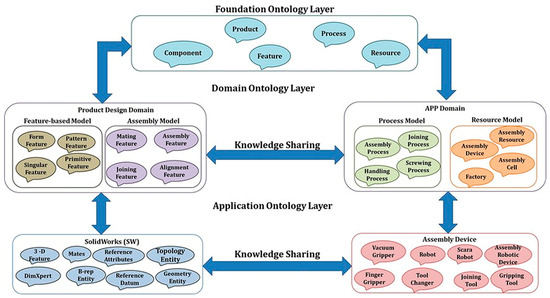
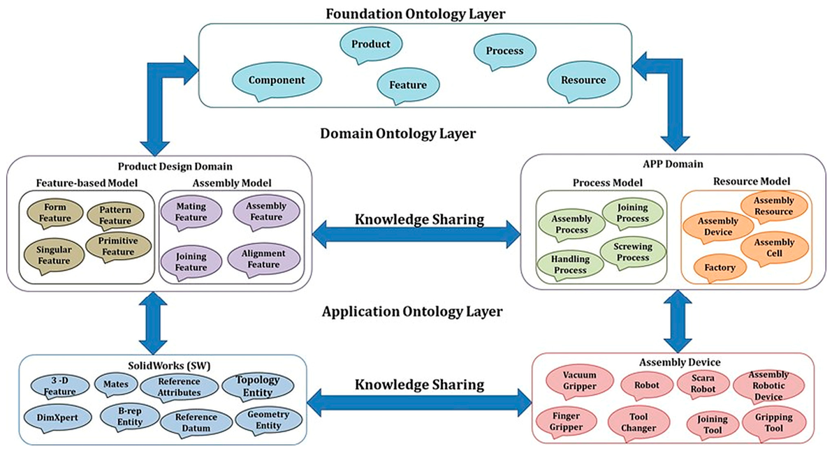
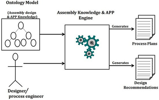
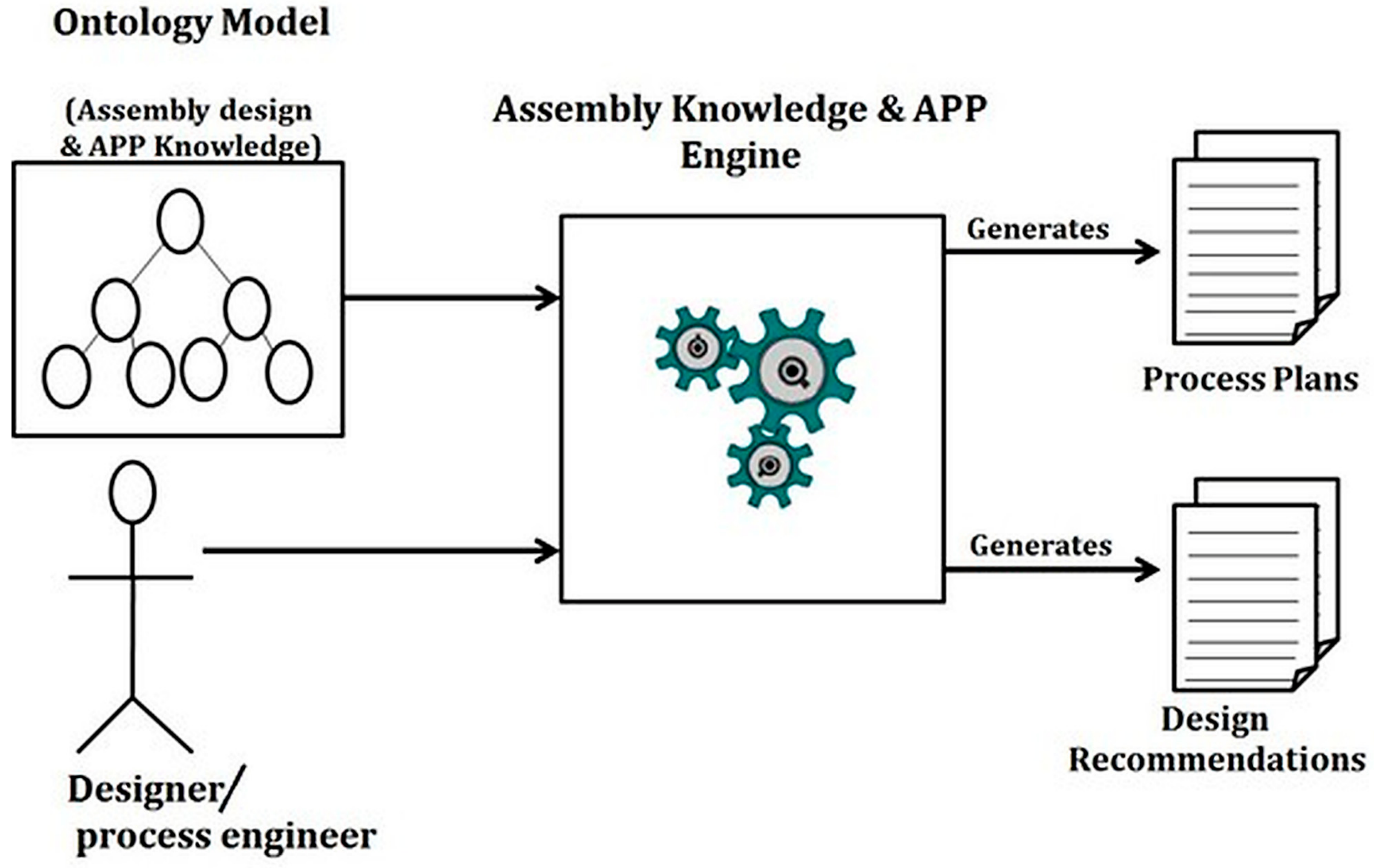
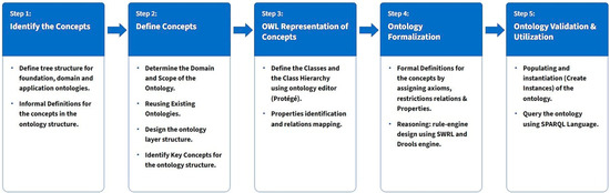
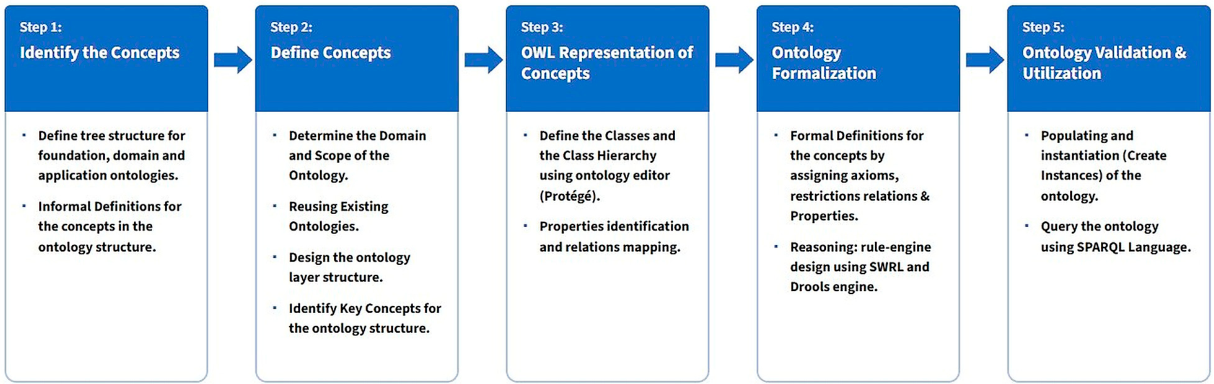
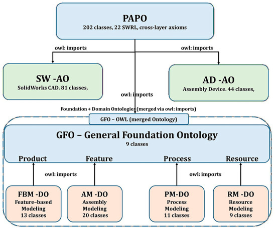
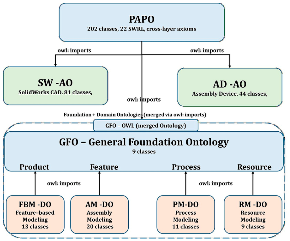
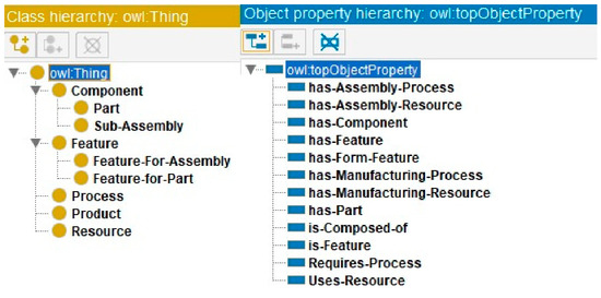
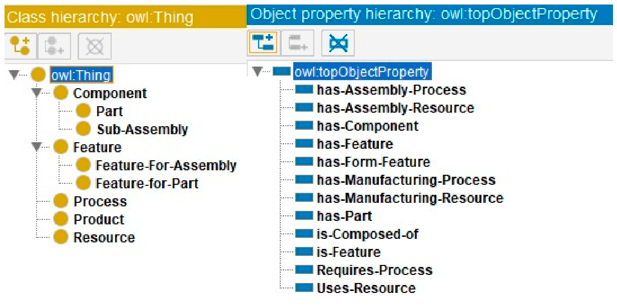
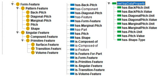
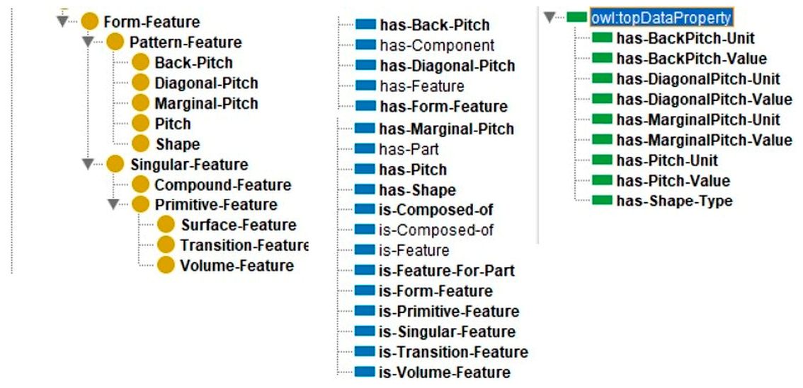
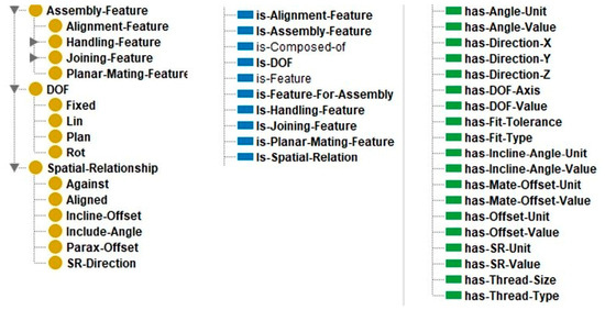
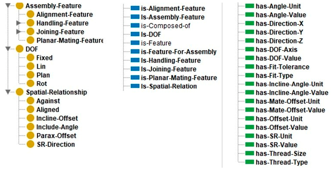
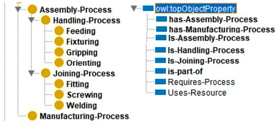
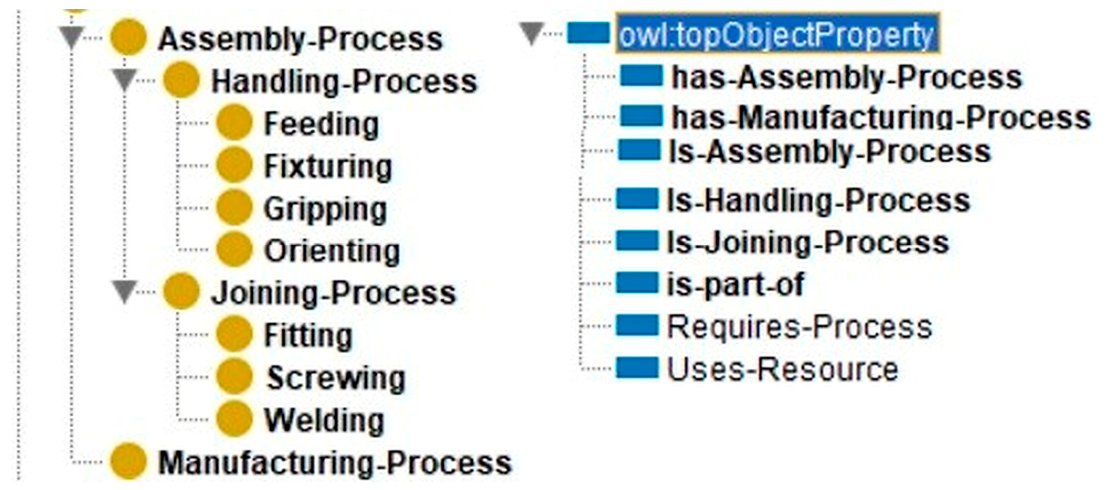
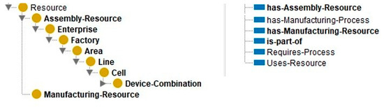
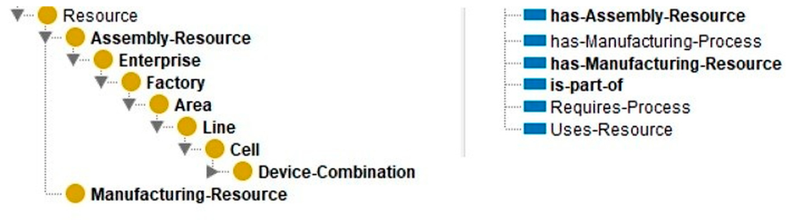
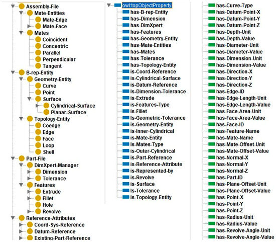
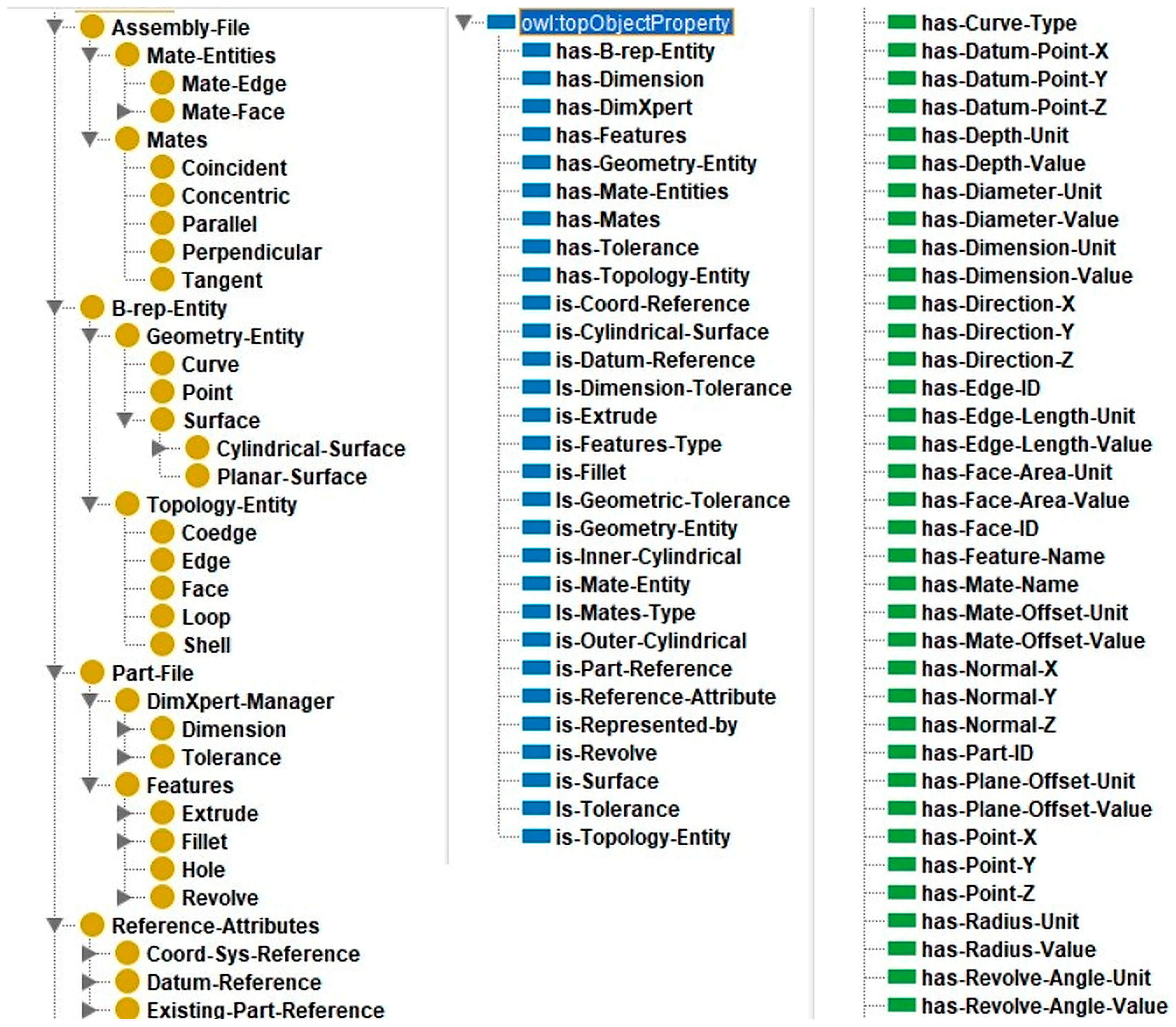
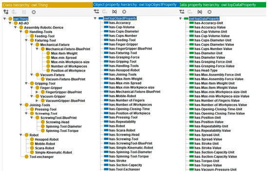
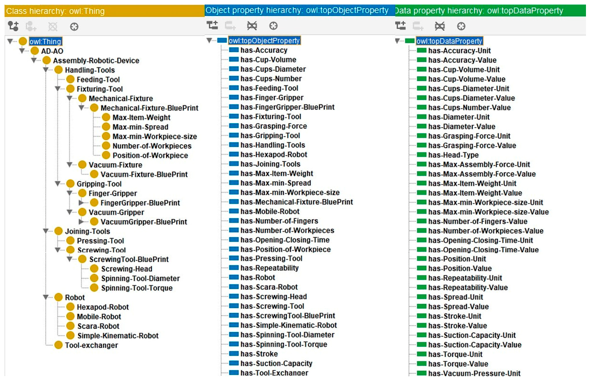
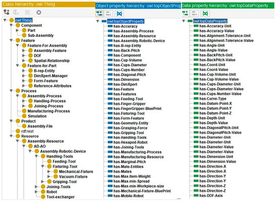
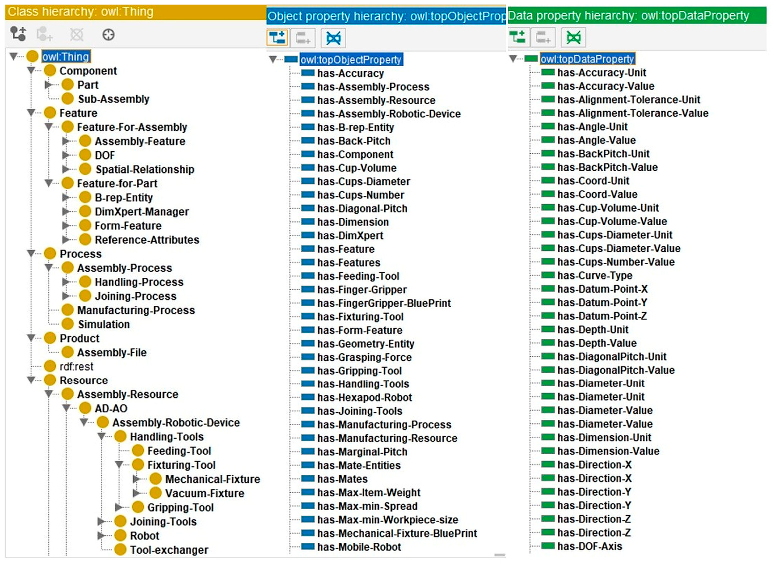
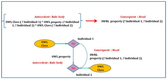
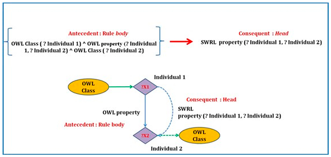
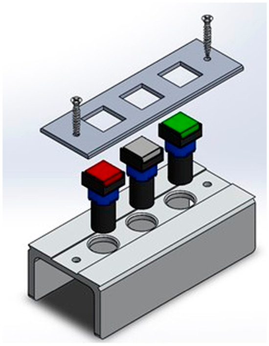
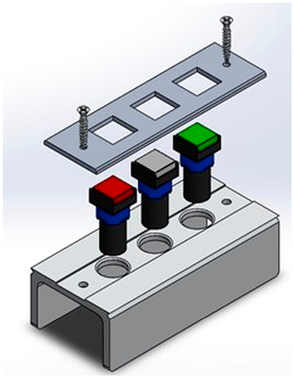
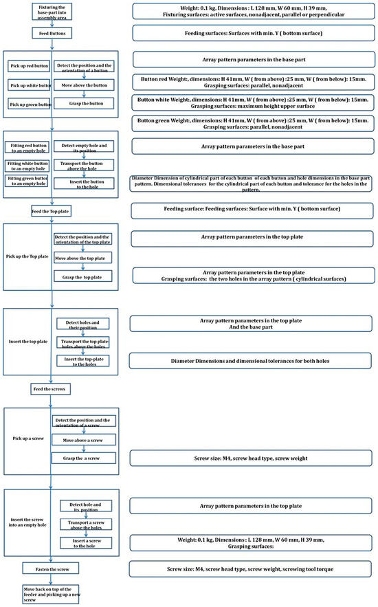
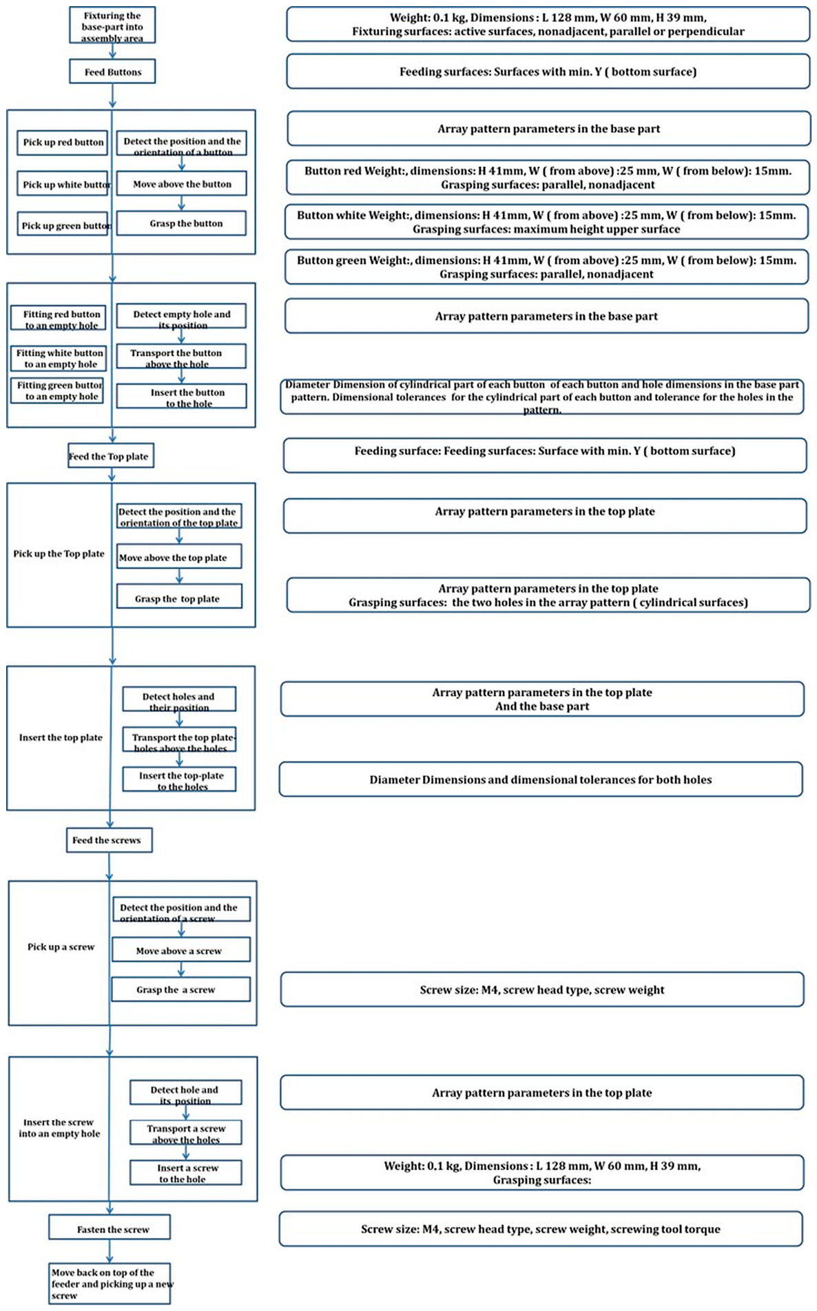
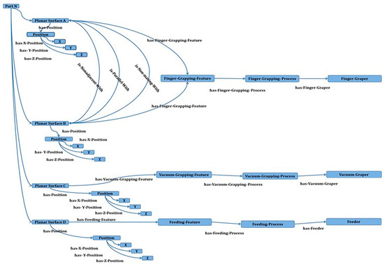
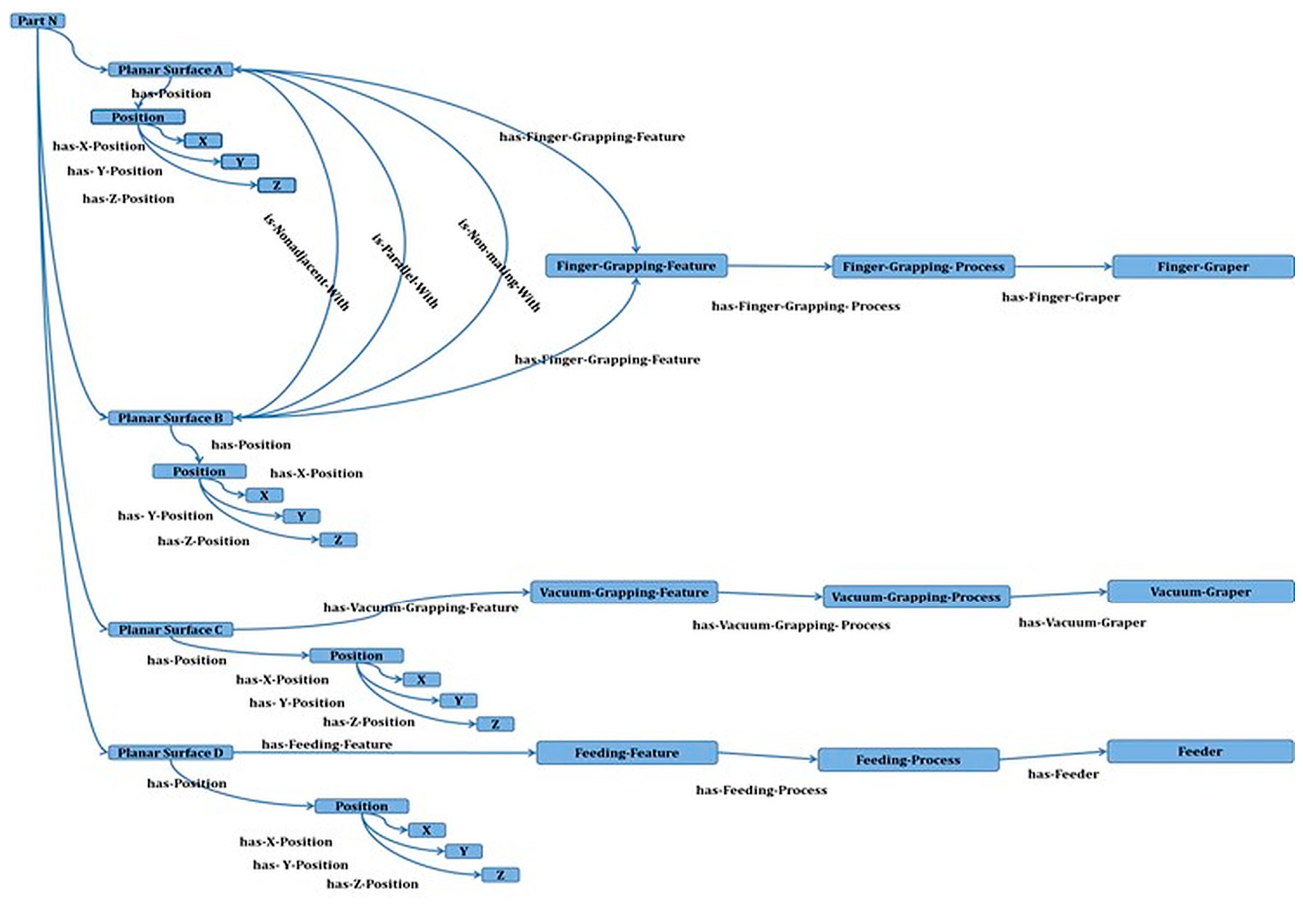
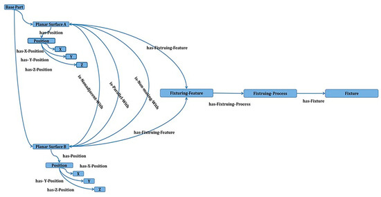
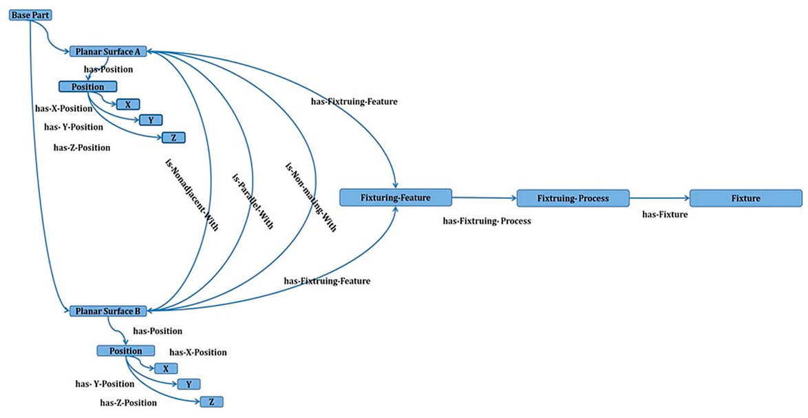
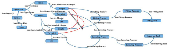
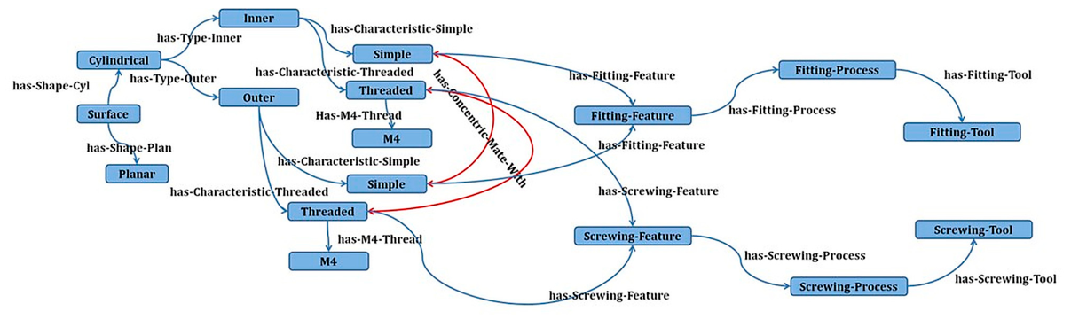
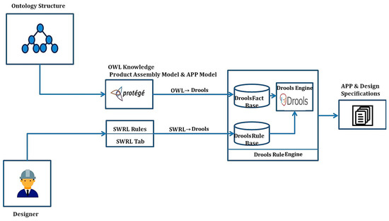
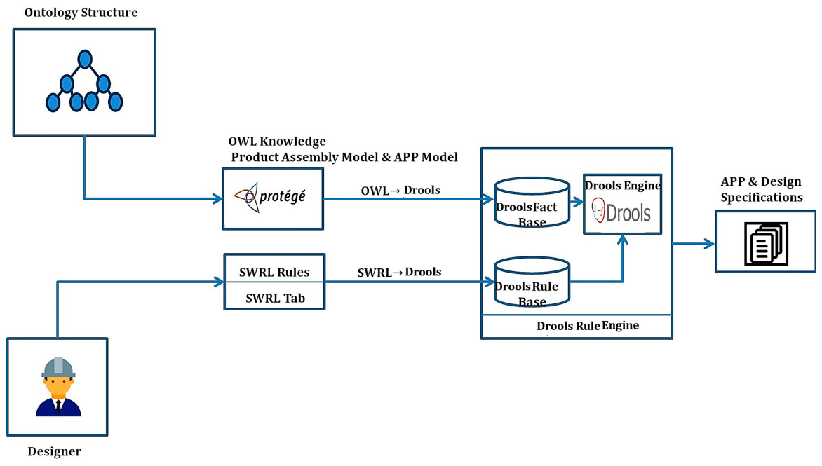
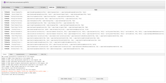
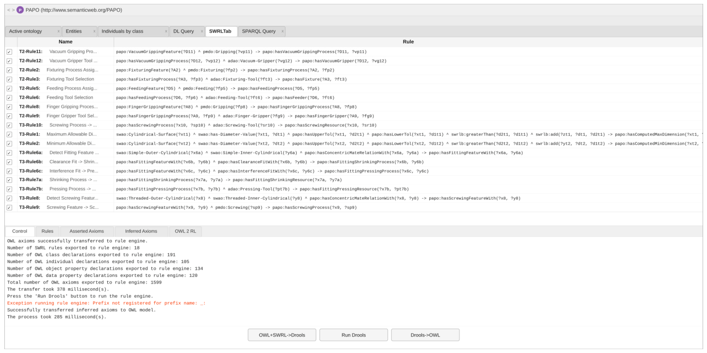
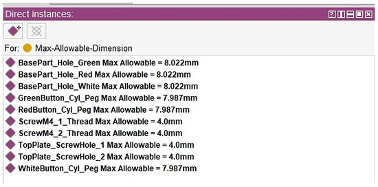
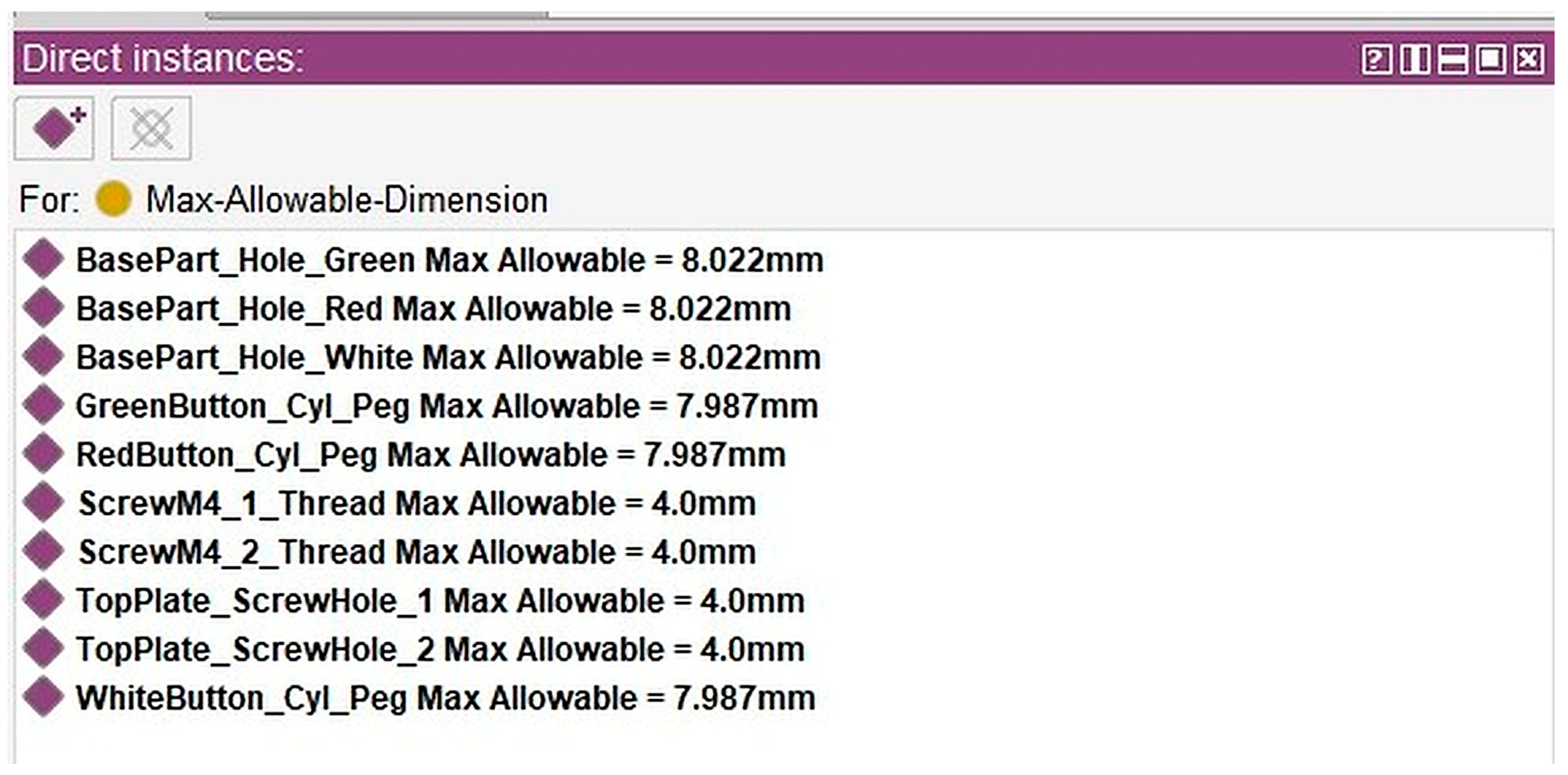
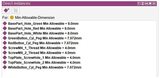
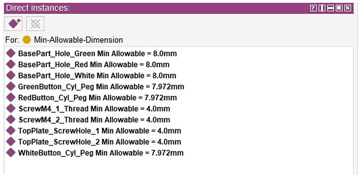
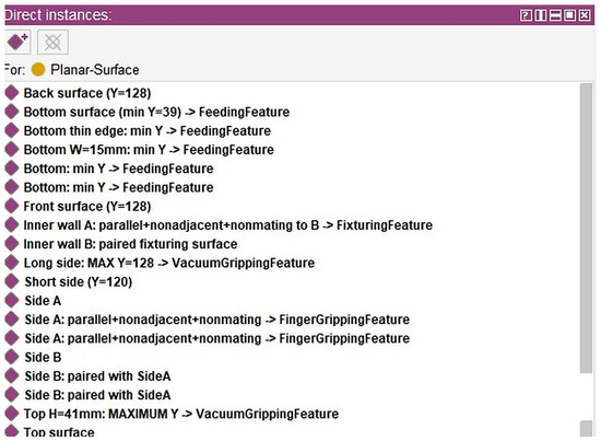
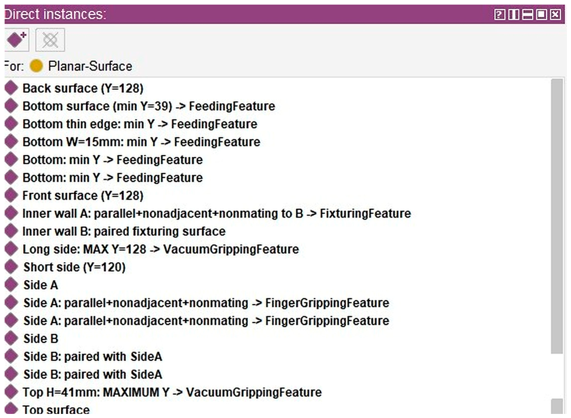
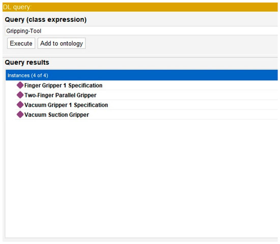
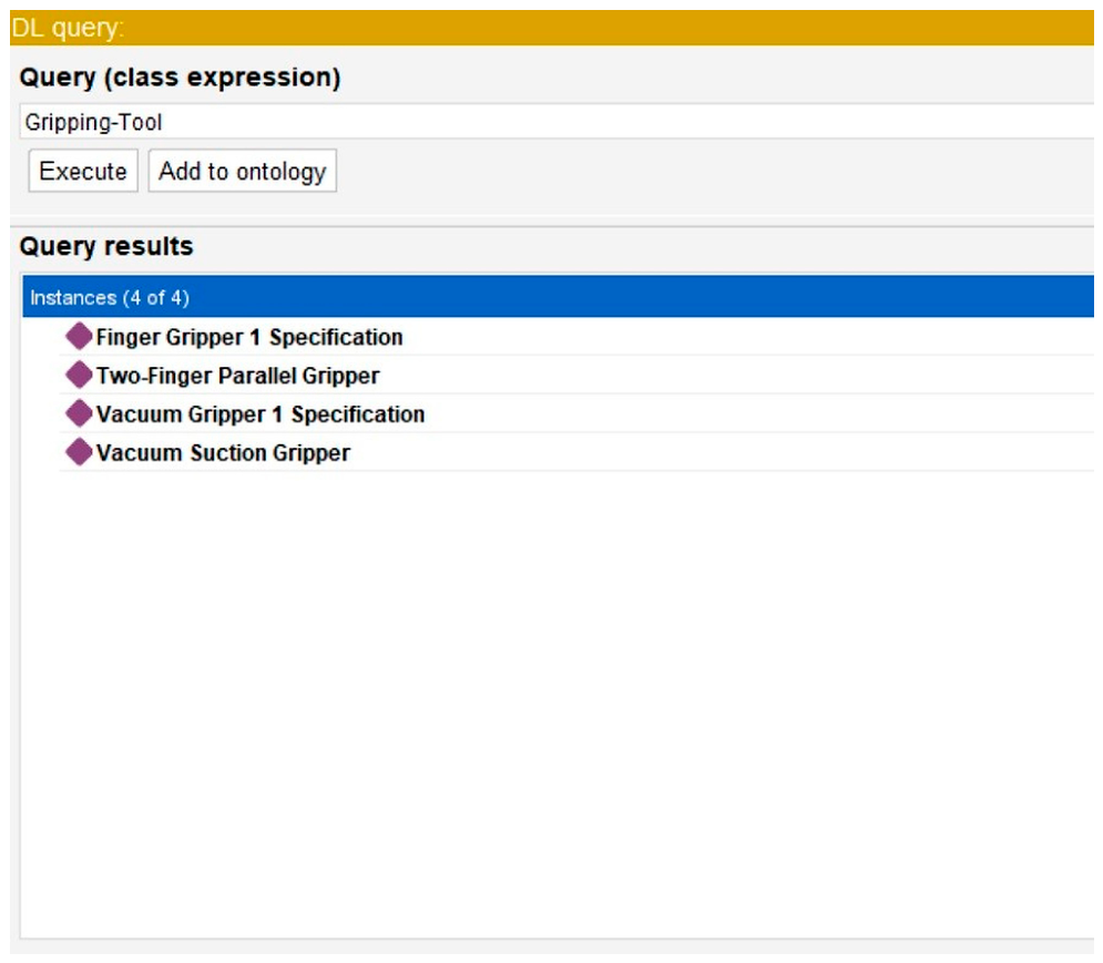
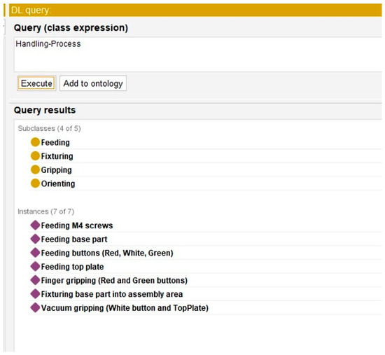
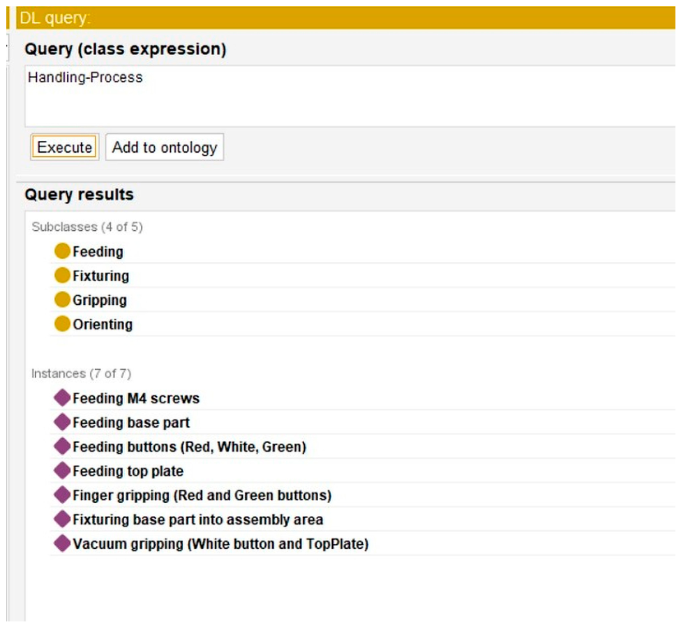
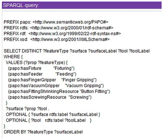
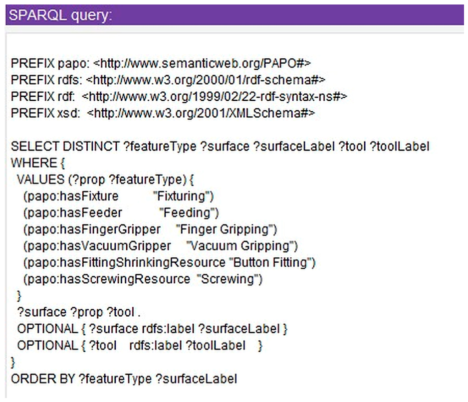
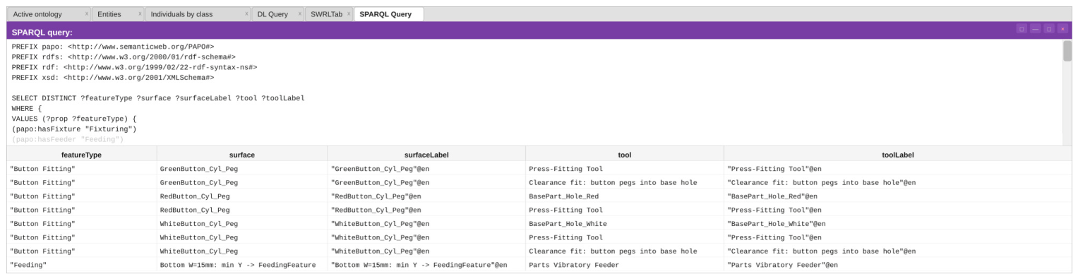
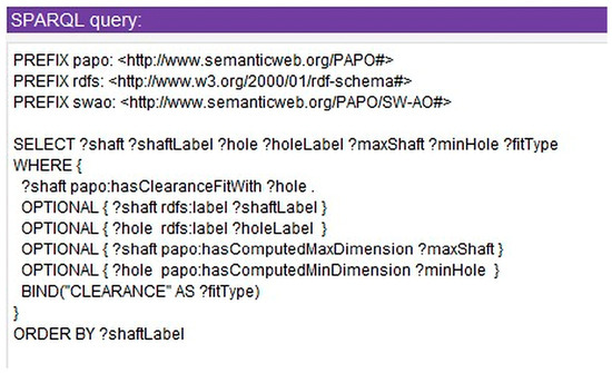

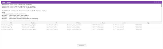
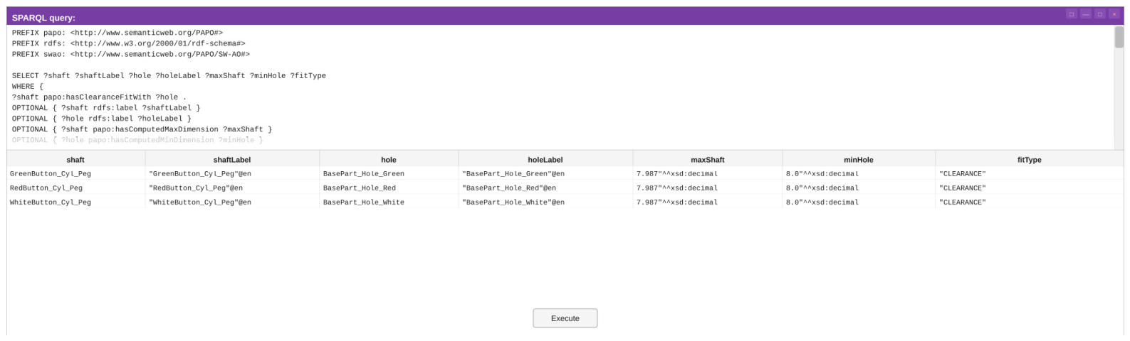
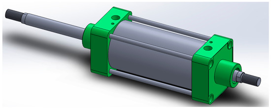
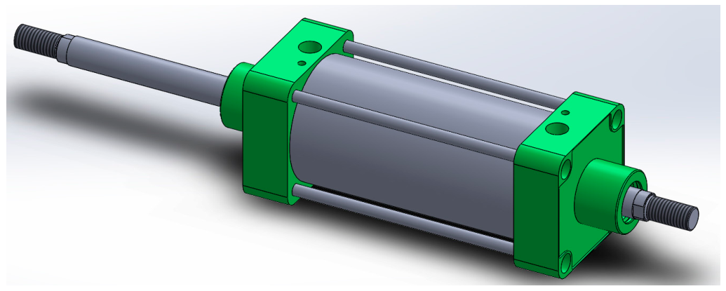
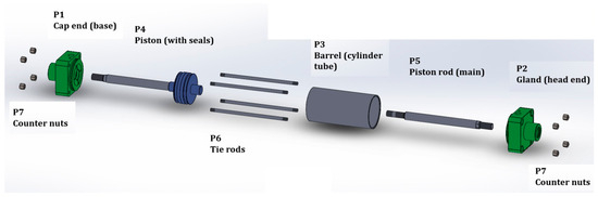
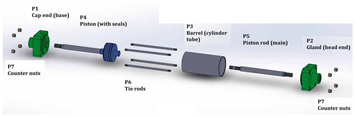
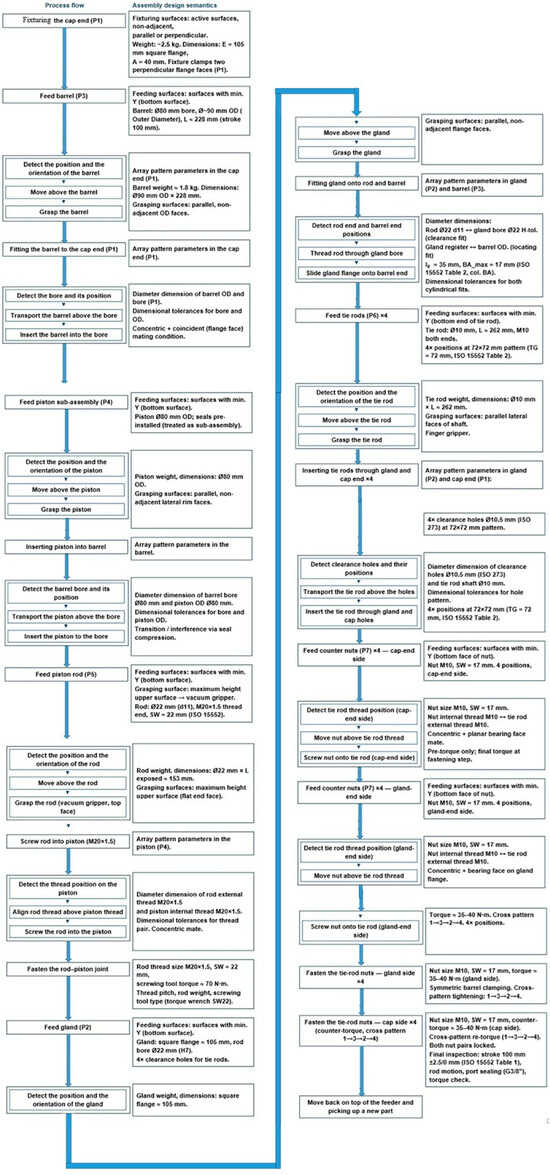
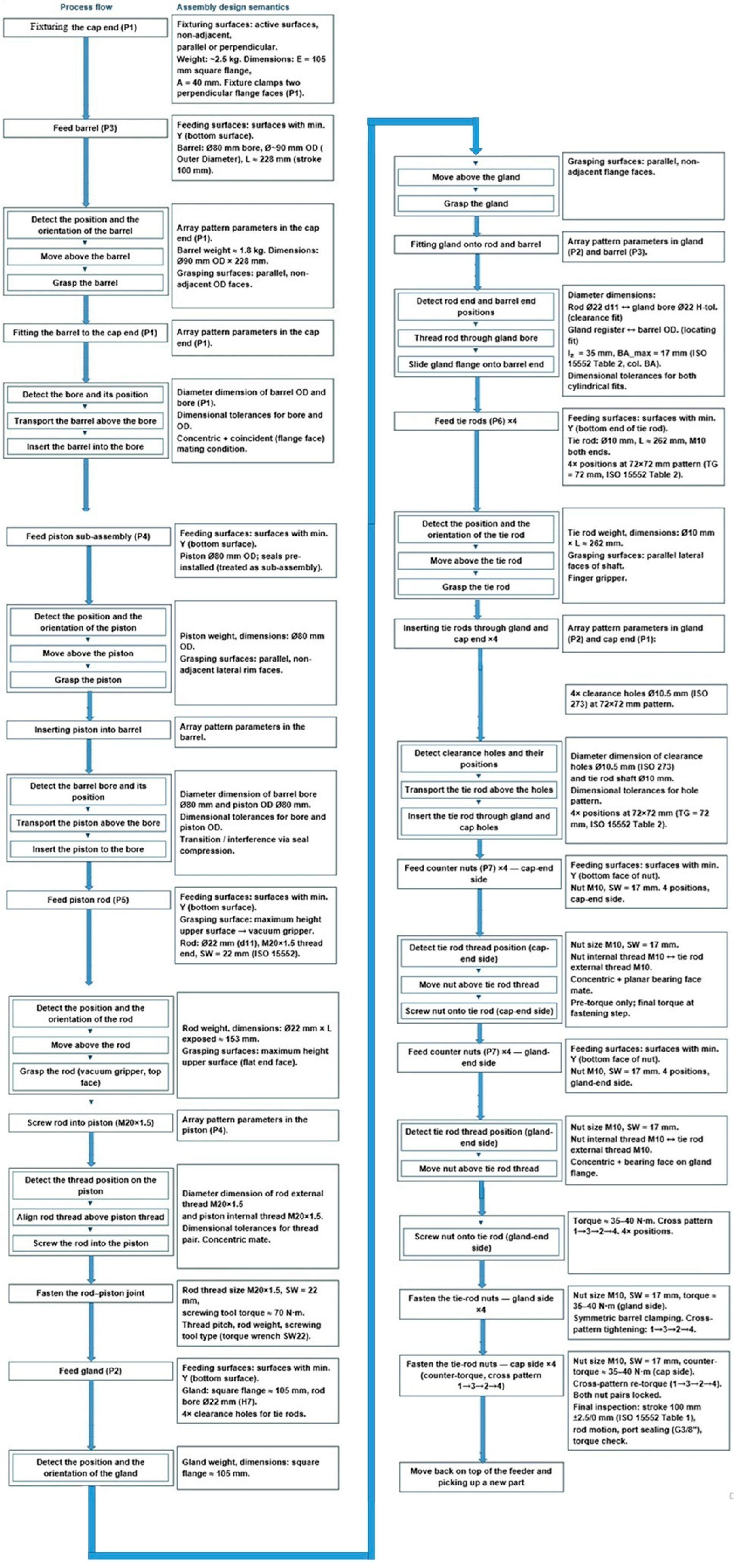
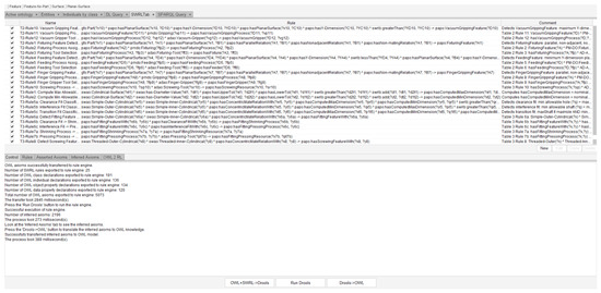
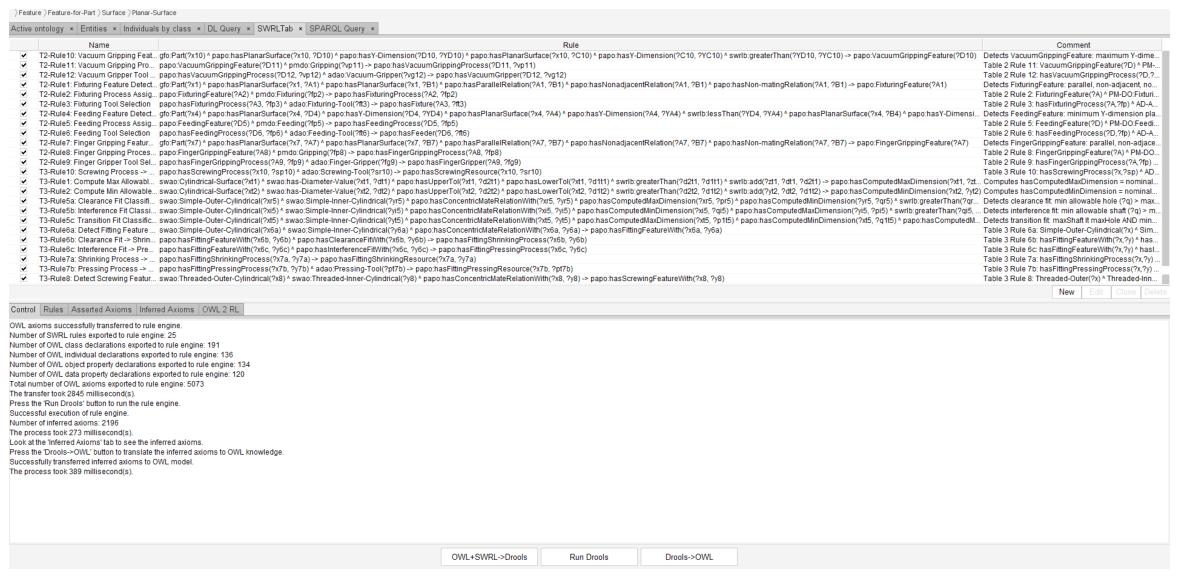
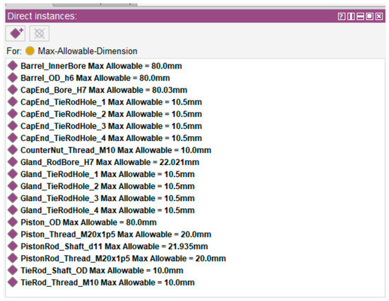
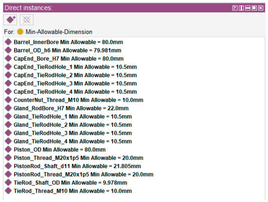
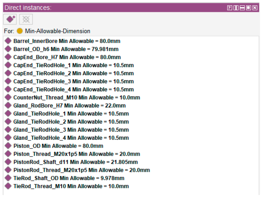
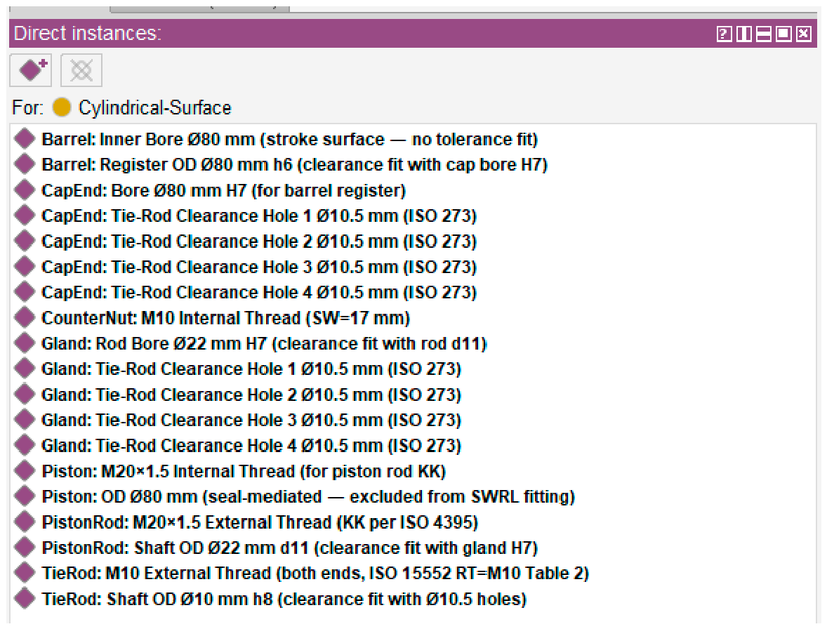
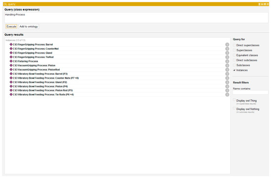
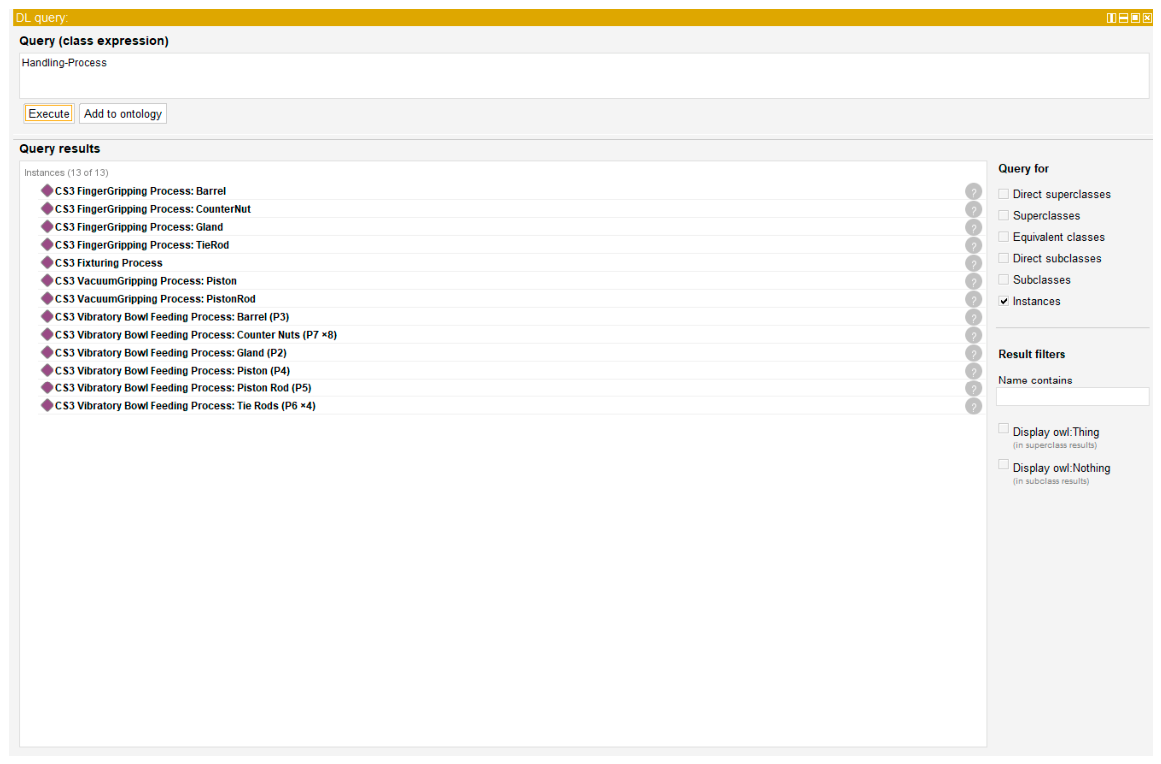
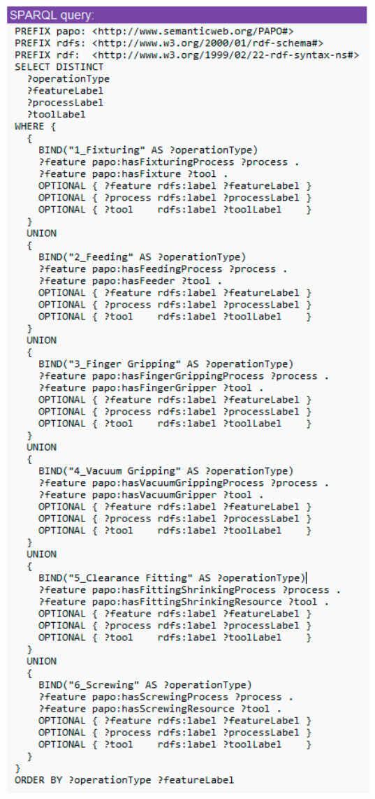
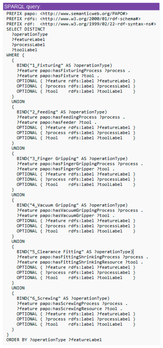
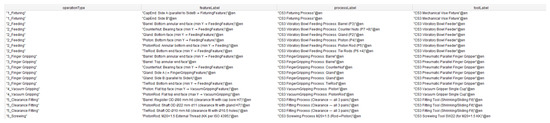
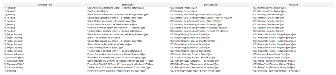
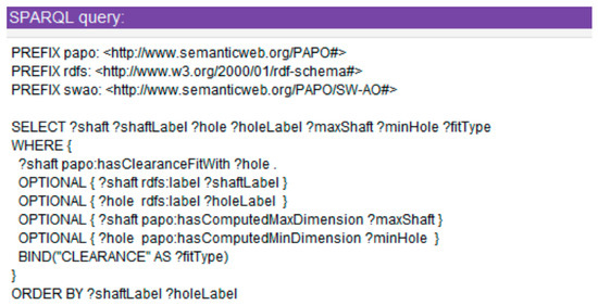
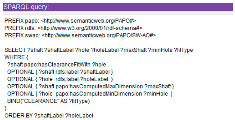



Disclaimer/Publisher’s Note: The statements, opinions and data contained in all publications are solely those of the individual author(s) and contributor(s) and not of MDPI and/or the editor(s). MDPI and/or the editor(s) disclaim responsibility for any injury to people or property resulting from any ideas, methods, instructions or products referred to in the content. |
© 2026 by the authors. Licensee MDPI, Basel, Switzerland. This article is an open access article distributed under the terms and conditions of the Creative Commons Attribution (CC BY) license.