


Abstract
Accurate prediction of store trajectories at the point of release from an unmanned/manned aircraft is an essential requirement for safety and precision. Captive Trajectory System (CTS) is a well-known feature of wind-tunnel testing to simulate the dynamics of store separation. To accurately replicate real-world aerodynamic conditions based on measured forces and moments, it utilizes a six-degree-of-freedom (6-DOF) robotic arm controlled by a closed-loop control system that solves the store’s equations of motion. In this study, a wing–pylon–store configuration is used as a sample case, and published experimental trajectories are used as input. A 6-DOF robotic arm named ROBO-S is designed to follow these trajectories in a CTS setup. The kinematic analysis of ROBO-S is performed in this study. The Denavit–Hartenberg (DH) method is used for the calculation of forward kinematics, whereas geometric techniques are used for inverse kinematics calculations. A simulation of kinematic analysis is performed in MATLAB R2021a. The mechanical design of ROBO-S is carried out in PTC CREO 9.0. MATLAB simulations confirm that the robotic arm can follow the trajectory obtained from published experimental results. To demonstrate the feasibility of the design, the robotic arm is fabricated using 3D printing. The results demonstrate the potential of the developed system in accurately following trajectories for wind-tunnel testing applications.
1. Introduction
The accurate prediction of store separation trajectories is crucial for ensuring the safety and precision of air-launched stores. With the increase in the operational flight speed of military aircrafts and combat UAVs, the challenges associated with store separation have increased. The flow field around aircraft and store is intricate because of the various factors such as downwash, side wash, and high dynamic pressure. In transonic and supersonic flow, the aircraft starts to encounter shock waves which interact with the surrounding flow field affecting the loads acting on the store. Full-scale flight testing to ensure compatibility of aircraft/store for a large number of flight conditions is not practical due to high costs, time constraints, and safety risks.
Wind-tunnel testing provides an efficient method for evaluating store separation dynamics. Captive Trajectory System (CTS) is used in wind tunnels for the prediction and analysis of store separation trajectories. CTS was introduced in the 1960s for wind tunnel testing of store separation. This system is primarily used for the trajectory analysis of stores launched in air and acts as a separation simulator that utilizes the wind tunnel as an analog function generator for forces on store when the store is in the flow field of the parent aircraft.
The CTS hardware comprise a 6-DOF support system for store which is basically a 6-DOF robotic arm. A closed-loop digital computer system is used to control the motion of the robotic manipulator. This system can solve the equations of motion by using mass and inertia of the store and aerodynamic forces measured during the wind-tunnel test. The -6-DOF robotic arm is a critical component of CTS that moves the store on the trajectory obtained from aerodynamic load conditions during wind-tunnel tests. Designing a robotic manipulator for CTS requires careful consideration of kinematic modeling, structural design, and control accuracy to ensure precise trajectory tracking. This study aims to design, simulate, and implement a 6-DOF robotic manipulator specifically for CTS applications in wind-tunnel testing.
1.1. Problem Statement and Motivation
The designing of a robotic manipulator for CTS applications presents various technical challenges. The robotic arm must be capable of accurately executing coupled 6-DOF motions dictated by experimentally determined store separation trajectories. In addition to position tracking, precise control of orientation is also essential as small angular deviations can greatly influence the aerodynamic loading environment. Also, the manipulator must operate within strict workspace constraints which are imposed by the wind tunnel and test model geometry.
Despite being the essential component of CTS operations, very limited publicly available information exists about the systematic kinematic design, modeling, and experimental validation of robotic manipulators developed for CTS applications. This motivates the need for a dedicated and transparent robotic framework that can track the separation trajectories and serve as a foundation for future CTS developments.
1.2. Research Gap
Existing studies about store separation mainly focuses on aerodynamic modeling, force measurement techniques, and trajectory prediction. The robotic manipulators used in CTS setups are generally treated as proprietary systems with very minimal technical details unveiled in the open literature. This results in a lack of openly available studies that give a complete kinematic formulation, workspace analysis, and experimental validation of a 6-DOF robotic manipulator specifically designed for CTS applications.
The available literature mainly addresses forward and inverse kinematics, trajectory tracking, and simulation of generic 6-DOF manipulators [1,2,3,4,5,6]. However, these studies are mostly about the industrial or service robotics applications and do not explicitly correspond to the unique operational requirements of CTS. As a result, an evident gap exists in the literature for a reproducible and CTS application-specific kinematic framework.
1.3. Purpose of the Experiment
The purpose of this study is to develop and validate the kinematic design of the 6-DOF robotic manipulator specifically designed for CTS applications and to demonstrate its ability to track published store separation trajectories obtained from wind-tunnel testing. To address this purpose, the following research questions are investigated in this study:
- RQ1: Can a 6-DOF robotic manipulator be kinematically designed by using closed-form forward and inverse kinematics in order to satisfy the workspace and motion related requirements of CTS?
- RQ2: Can the derived kinematic model accurately track experimentally obtained 6-DOF store separation trajectories in a simulation environment?
- RQ3: Can the same kinematic framework be implemented on a physical prototype and reasonable trajectory tracking performance is demonstrated under practical hardware constraints?
2. Related Work and Background
Captive Trajectory Systems have been in use for several decades as an experimental technique for investigating store separation in wind tunnels. Since their introduction in the 1960s, CTS has been widely used to predict and analyze store separation trajectories by measuring aerodynamic forces and moments acting on the store when it is in the flow field of the parent aircraft. The wind tunnel is effectively used as an analog function generator, where measured aerodynamic loads are utilized to compute the store motion. The majority of CTS-related studies reported in the literature primarily focus on aerodynamic measurements, trajectory prediction, and experimental validation of store separation behavior [7,8]. Very limited attention is given to the detailed design and modeling of the robotic manipulator responsible for moving the store along the experimentally determined trajectory. CTS hardware concepts and support system developed initially are reported in [9,10]. Extensive operational experience related to store separation testing, gathered over several decades, was summarized in [11]. Research studies have also addressed store trajectory prediction and optimization from an aerodynamic point of view such as guided store separation trajectory optimization, reported in [12].
Various wind-tunnel facilities have documented the development of CTS hardware and experimental setups. The CTS framework for a 1.2 m transonic wind tunnel and the FL-24 wind tunnel were presented in [13,14]. CTS testing techniques utilized in the FL-2 wind tunnel were discussed in [15]. More recent studies have investigated the use of robotic manipulators for CTS applications. A 3-DOF robotic arm designed for captive trajectory simulation was reported in [16] to show the feasibility trajectory execution by the manipulator; however, the studied manipulator had limited motion capability. A system-level CTS design including kinematic modeling and controller design was proposed in [17], but the manipulator subsystem was validated through simulation. A 3-DOF aircraft manipulator system was proposed for virtual flight testing in a wind tunnel [18]. This study demonstrated inverse kinematics-based trajectory tracking but with restricted degrees of freedom and a focus on longitudinal flight dynamics only. So, CTS hardware and experimental methodologies have been reported in the literature, but openly available detailed kinematic formulations of robotic manipulators specifically designed for CTS applications is very limited.
In contrast, the kinematic modeling of robotic manipulators for various general applications has been studied extensively and is well-established in the literature. Kinematic analysis is the basis of analyzing, controlling, and predicting the manipulator’s trajectory tracking performance with accuracy [19]. Forward and inverse kinematics, workspace analysis, and analytical solution methodologies have been widely addressed in classical robotics textbooks. The inverse kinematics problem is inherently complex and often holds multiple solutions [20,21]. Inverse kinematics is studied extensively using geometric methods, matrix-based approaches [22], screw theory and other analytical techniques and is considered as one of the most challenging problems in robotics research [23,24]. Kinematic modeling and simulation of serial manipulators using MATLAB R2021a and CAD-integrated environments for generic industrial and service robotics applications have been established in numerous studies [25,26,27,28]. These studies included closed-form and numerical inverse kinematics solutions for multi-DOF systems [29]. Despite the maturity of robotic kinematic theory, these studies are mostly for general purpose manipulators. Also, these studies do not explicitly address the unique requirements and constraints that are associated with CTS operation in wind tunnels, which includes trajectory tracking driven by aerodynamic loads measured experimentally and have strict workspace limitations.
Recently, artificial intelligence and data-driven methodologies have been applied increasingly in robotics. These methodologies are primarily used for condition monitoring, fault diagnosis, and reliability enhancement of robotic components. Deep learning-based attention guided feature aggregation networks are proposed for servo motor bearing fault diagnosis, and machine learning-based electrical current signature analysis is used for fault detection in robotic RV reducers and data-driven prognostic health management approaches are developed for strain wave gear reducers operating under variable speed conditions [30,31,32,33]. Review studies have also discussed recent developments and challenges in AI-enabled health assessment for smart factory and intelligent robotic systems. In this context, the present work focuses on the kinematic modeling and trajectory execution aspects required for CTS operation, which represent a fundamental layer upon which advanced monitoring or AI-based strategies could be incorporated in future developments.
Despite the extensive work on store separation aerodynamics, experimental CTS hardware, general robotic kinematic modeling, and AI-based health monitoring of robotic systems, openly available studies that present a complete and experimentally validated kinematic framework specifically developed for 6-DOF robotic manipulators in Captive Trajectory Systems are very limited. Particularly, detailed description of forward and inverse kinematics, workspace considerations, and prototype-level validation tailored to CTS applications are rarely reported in the open literature. The present work seeks to address this gap by focusing on the kinematic design, analysis, simulation, and prototype validation of the 6-DOF robotic manipulator intended for CTS use.
3. Materials and Methods
This study follows a well-structured methodology to design and develop a robotic manipulator for CTS applications in wind-tunnel testing. The sample store separation trajectory is taken from published experimental results and serves as the input for trajectory planning for the subject robotic arm [34]. During the conceptual design phase, the initial workspace, degrees of freedom and payload capacity are estimated to guide the overall configuration. The mechanical design (CAD modeling) of the manipulator is performed in PTC CREO 9.0. Kinematics analysis is performed using MATLAB, where Denavit–Hartenberg (DH) methodology is utilized for the calculation of forward kinematics and geometric techniques are used for inverse kinematics to achieve precise trajectory tracking. The workspace of the final design is determined based on the kinematic analysis. The motion of the manipulator is then simulated in MATLAB R2021a to evaluate its ability to follow the desired trajectory. After validation, a prototype of the 6-DOF robotic arm is fabricated using 3D printing for demonstration purposes. Figure 1 illustrates the overall workflow of the study while details of these steps are described in the subsequent sections.
Figure 1.
Sequential workflow of the study.
3.1. Sample Trajectory
The sample trajectory used in this study is obtained from published experimental data in which testing was conducted on a wing–pylon–store configuration in the Aerodynamic Wind Tunnel (4T) at the Arnold Engineering Development Center (AEDC) at Mach 0.95. This trajectory, defined in terms of three displacements and three orientations, will serve as the input for the robotic manipulator developed in this research. The AEDC (4T) transonic wind tunnel is a closed-loop, continuous-flow, variable-density tunnel where Mach numbers can be varied from 0.1 to 1.1 continuously and from 1.1 to 2.0 in intervals of 0.1 using a flexible nozzle [34].
3.2. Kinematics Modeling of 6-DOF Manipulator
The kinematics analysis lays the foundation for the development of a 6-DOF robotic manipulator named ROBO-S, specifically designed to precisely navigate along the store trajectory. For manipulators, the position/orientation of the end effector is determined by the joint variables. Physical constraints of the joints limit the motion of the end effector. The relationship between the joint variables and the motion of the end effector is critical for designing and controlling robotic systems. Kinematic analysis involves understanding the relative motions between various links of a robot manipulator [35].
In robotics, a serial manipulator having n degrees of freedom comprises a base link and n moving links, which are connected in sequence by n joints to create an open kinematic chain. Each joint enables relative motion that is controlled by an actuator, allowing the end effector to be positioned anywhere in the workspace of manipulator.
3.2.1. Forward Kinematics Analysis Using Denavit–Hartenberg (DH) Convention
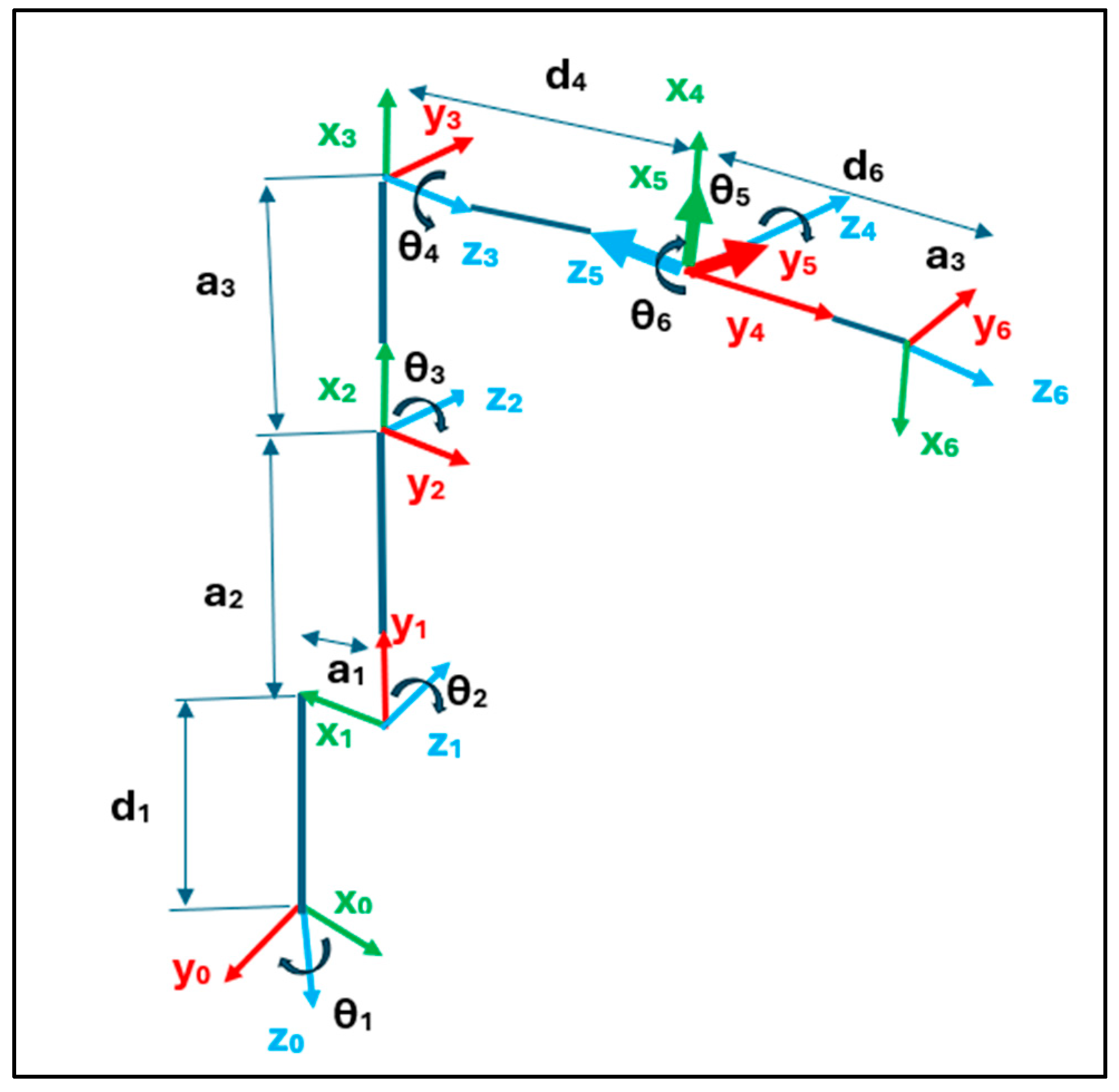
To systematically describe the position and orientation of the links, the DH convention is adopted. This convention attaches a Cartesian coordinate system to all links, ensuring consistent and standardized kinematic representation as shown in Figure 2. The standard procedure for establishing DH coordinate system was applied and DH parameters were identified for ROBO-S. The DH parameters for ROBO-S are summarized in Table 1.
Figure 2.
DH parameter representation of ROBO-S.
Table 1.
DH parameters for ROBO-S.
After defining a coordinate system for all links, a homogeneous transformation matrix can be derived to relate two successive coordinate systems. Forward kinematics analysis determines the position and orientation of the end effector by substituting the joint angles into the homogeneous transformation matrix connecting joints 1 and . Homogenous transformation matrix relating two successive coordinate references can be expressed in standard form as
where represents the joint angle of the i-th revolute joint, and define the link length and offset, respectively, and represents the twist angle between successive joint axes. These parameters collectively define the geometry and motion capability of the robotic manipulator and directly influence its reachable workspace and orientation envelope.
The overall transformation from the base frame to the end-effector frame can be determined by multiplying the transformation matrices successively:
where represent the elements of the rotation matrix defining the orientation of the store model and denote its Cartesian position, which together specify the six-degree-of-freedom pose used to accurately position the store model within the wind tunnel.
3.2.2. Inverse Kinematics Analysis
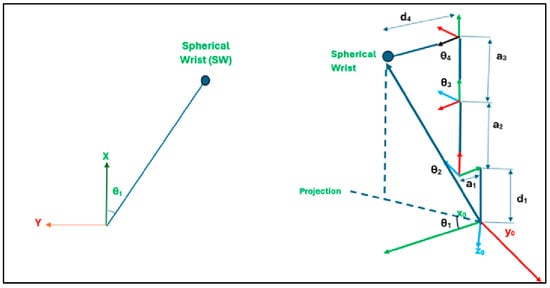
This section provides a detailed geometric approach to solve the inverse kinematics for a 6-DOF robotic manipulator, ROBO-S. The method incorporates geometric principles and vector mathematics to determine the joint angles required for a given robot configuration in space. The inverse kinematics calculations assume the robot is initially in an “L-shaped” configuration, with all joint angles set to zero, as shown in Figure 2. The calculations are simplified due to the wrist mechanism having three intersecting axes (axes 4, 5, and 6). These axes converge at a point, forming the spherical wrist (the intersection of joints J4, J5, and J6). The spherical wrist determines the orientation of the robot’s end-effector, while joints J1, J2, and J3 govern its position. To address the inverse kinematics problem, the spherical wrist’s position and orientation are calculated first. From this, the angle for joint 1 is determined. If a tool is attached, the calculations proceed from the tool back to the end-effector and then from the end-effector to the spherical wrist. As shown in Figure 3, the first four links of the robot consistently lie in the same plane, which is perpendicular to the horizontal plane. Consequently, the angle of the first joint can be determined by projecting the plane containing these four links.
Figure 3.
Calculation for joint angle 1.
Two solutions for :
This formulation provide two feasible solutions for the base joint, allowing for selecting the configuration that best satisfies the CTS workspace constraints and avoids mechanical interference with the wind-tunnel test section.
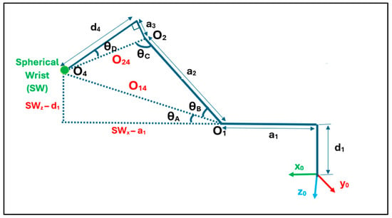
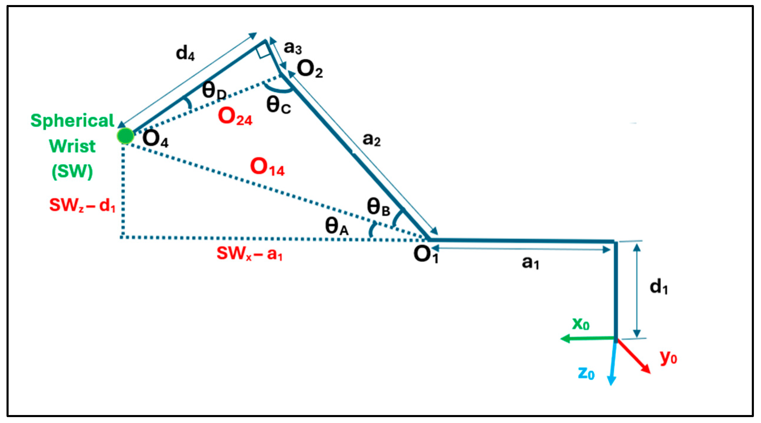
To determine the angle of joint 3, the distance between the origins of axis 1, i.e., , and axis 4, i.e., , is calculated. This distance is represented by as shown in Figure 4.
Figure 4.
Calculation for joint angles 2 and 3.
is calculated using the law of cosines
Whereas
The geometric construction of distances and angles enables a closed-form solution for joints 2 and 3 to ensure computationally efficient and numerically stable determination of the store position under CTS operation.
The configurations of the spherical wrist relative to joint 2 yield different cases for :
If the spherical is behind joint 2:
If the spherical wrist is forward and below of joint 2:
Similarly, angle of joint 3 is given by
Explicit consideration of different spherical wrist positions relative to joint 2 allows for the systematic handling of multiple manipulator configurations, which is essential to maintain continuous and collision-free motion during CTS trajectory execution.
Joints 4, 5, and 6 represent the yaw, pitch, and roll of the spherical wrist. The orientation of these joints depends on joint 3, which must be calculated first. Subsequently, the wrist frame orientation is determined. By combining this with the overall wrist rotation relative to the global frame, the individual angles of joints 4, 5, and 6 can be extracted. The transformation matrix for joint 3 is calculated using the DH parameters:
By isolating the rotational component of the transformation matrix, the inverse kinematics solution is decoupled into position and orientation subproblems. This simplifies the computation and improves robustness for 6-DOF store positioning.
From this matrix, only the rotational component is used for further calculations. The inverse of the rotational matrix () is then computed. The overall wrist rotation matrix is then calculated using the rotation matrix, , from forward kinematics. By multiplying the inverse of rotation matrix with , we get the orientation of the spherical wrist, i.e., . From the rotation matrix , the joint angles are extracted using Euler angles. To avoid singularities (arising due to the spherical wrist’s ability to reach the same point from different orientations), the following formulation is employed:
First is calculated as the following:
For
Extracting the wrist joint angles from the relative rotation matrix yields a closed-form solution for the end-effector orientation while explicitly accounting for singular configurations. This is particularly important for CTS operation, where even small orientation errors can have a noticeable impact on the aerodynamic loading of the store model.
3.3. Workspace Analysis
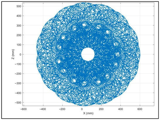
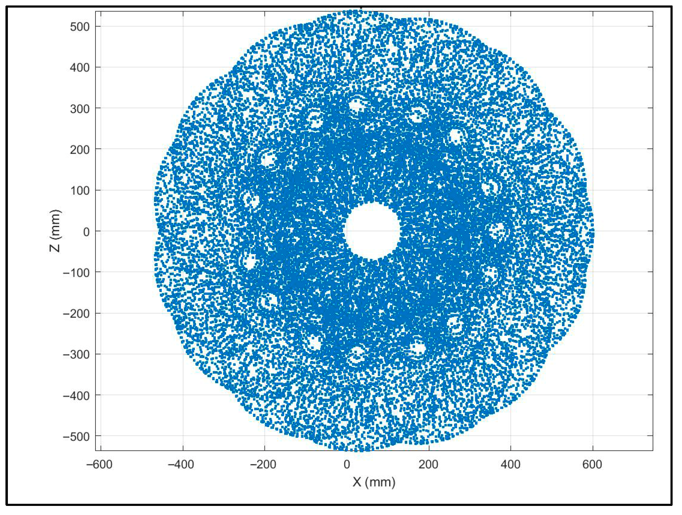
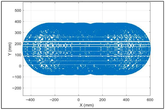
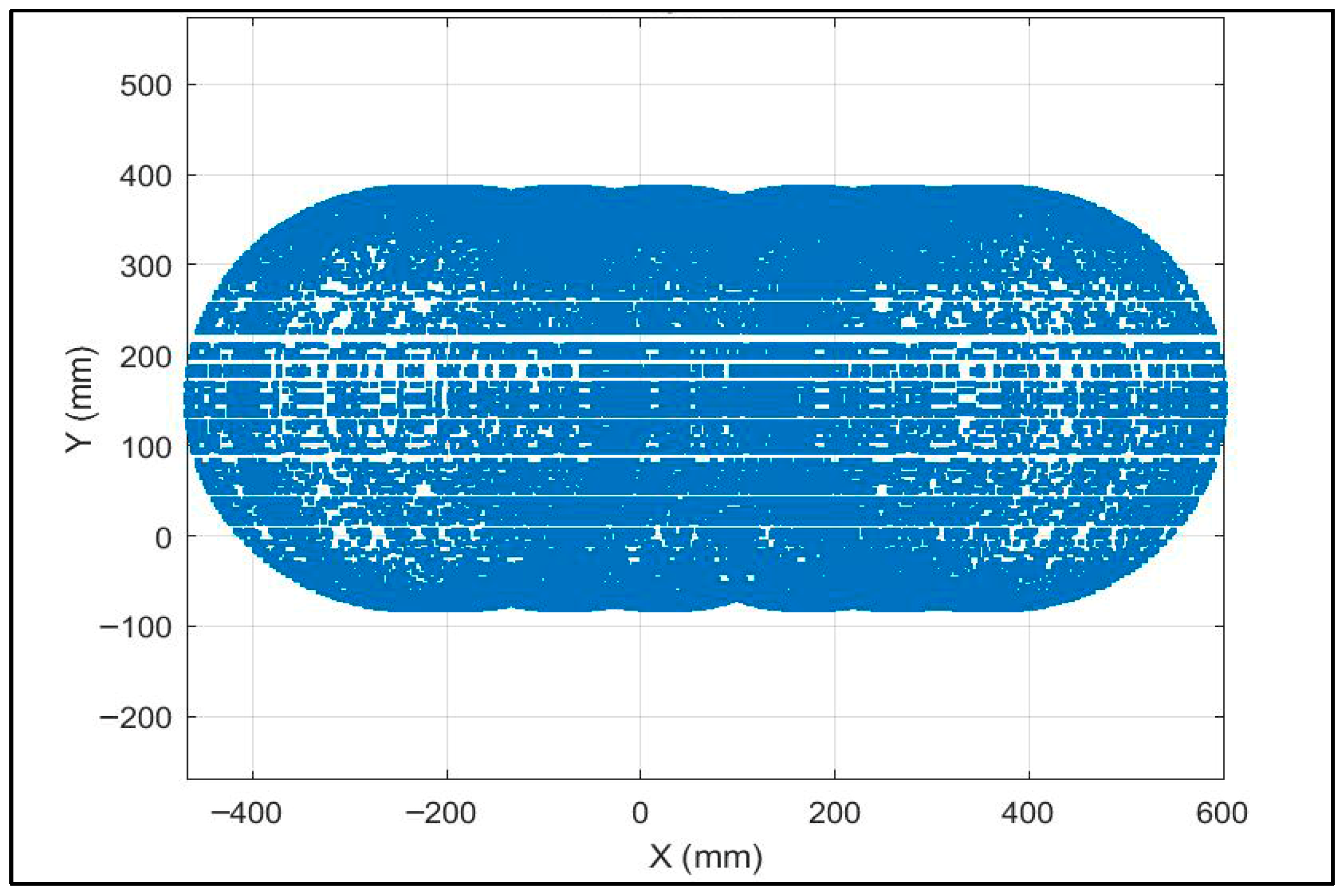
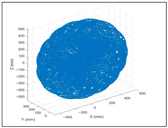
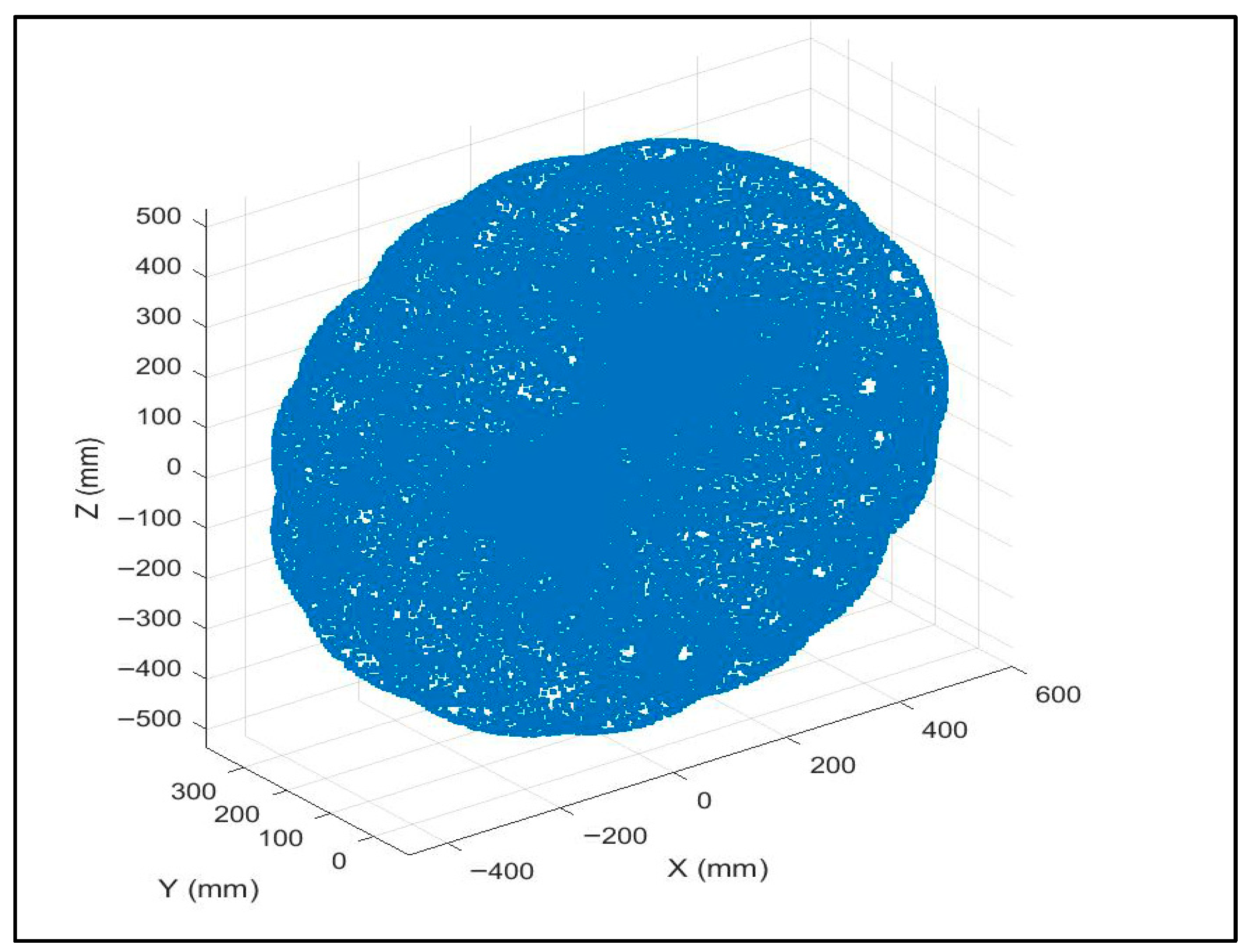
With advancement in robotics technology and an increase in the inclination towards incorporating robots in multiple applications, the robot’s workspace has become a primary performance parameter. The workspace of the robot expresses its ability to reach a specific area. If the joints’ Range of Motion (ROM) and links’ length are known, the workspace of the robotic manipulator can be determined. Workspace analysis of ROBO-S shows that the reach of the robot is approximately 600 mm. ROM and joint lengths for ROBO-S are given in Table 2. Workspace is graphically shown in Figure 5, Figure 6 and Figure 7.
Table 2.
Range of motion and joint lengths of ROBO-S.
Figure 5.
Workspace of ROBO-S in X-Z plane.
Figure 6.
Workspace of ROBO-S in X-Y plane.
Figure 7.
3D reachable workspace of ROBO-S.
3.4. Prototype Development
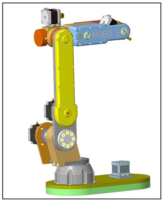
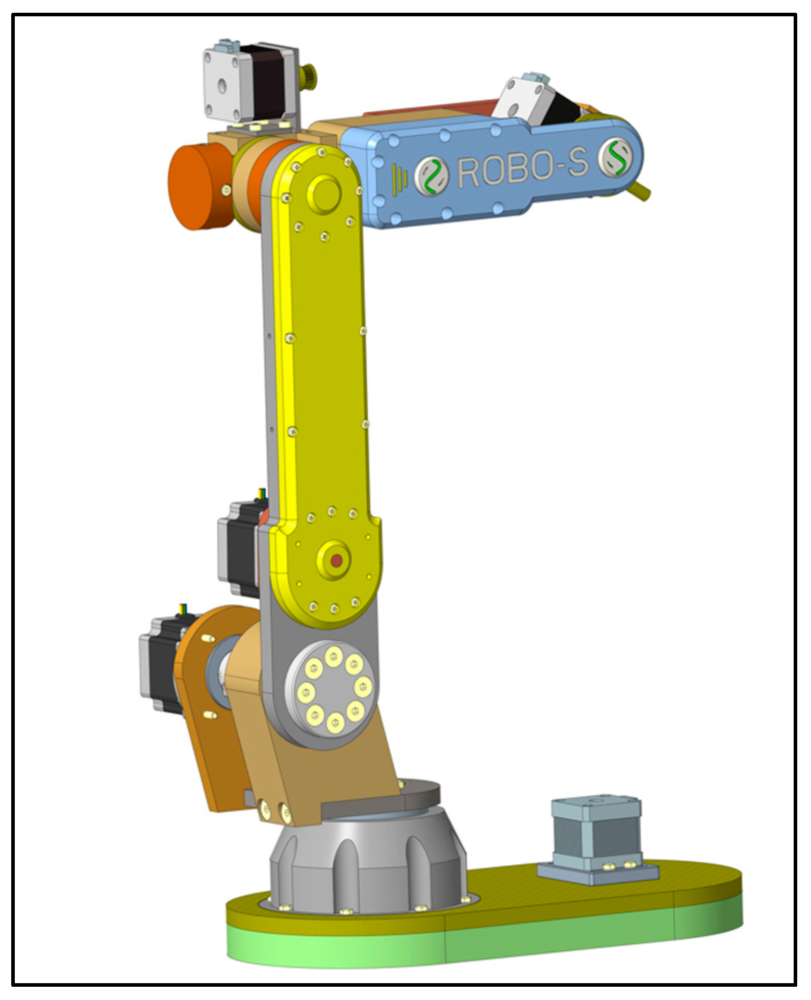
For the design of the ROBO-S robotic arm, PTC CREO 9.0 was utilized as the primary software for CAD modeling. Robust parametric design capabilities and advanced features of CREO enabled the creation of a detailed and precise 3D model of ROBO-S. Structural components of ROBO-S, including the base frame, links and joints are designed with careful consideration for functionality, structural integrity, and motion constraints. The CAD model serves as the blueprint for 3D printing and hardware integration (Figure 8).
Figure 8.
ROBO-S assembly.
Table 3 lists the hardware selected for each joint and other critical elements used:
Table 3.
Hardware description of ROBO-S.
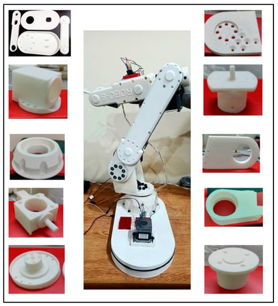
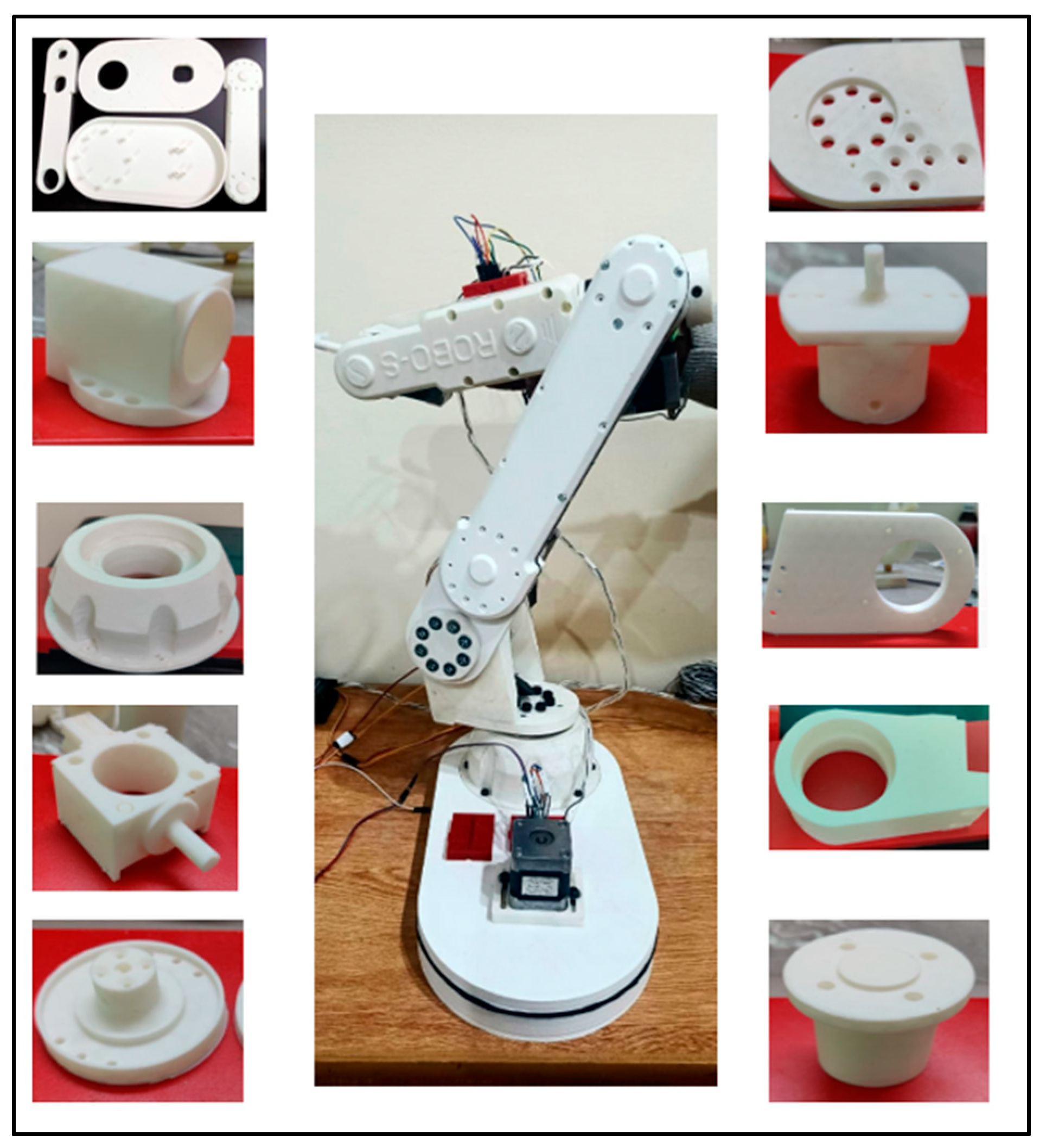
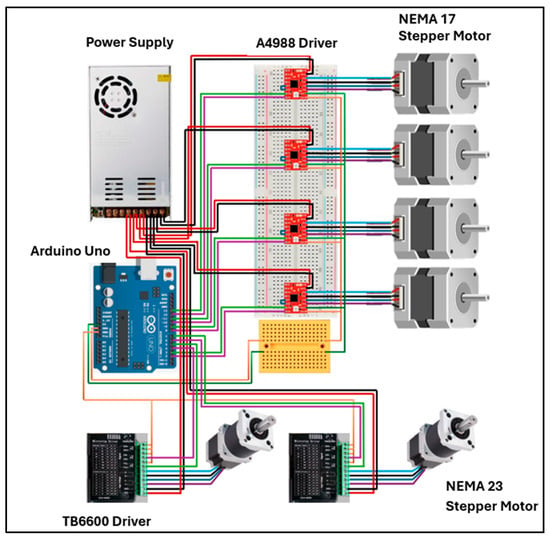
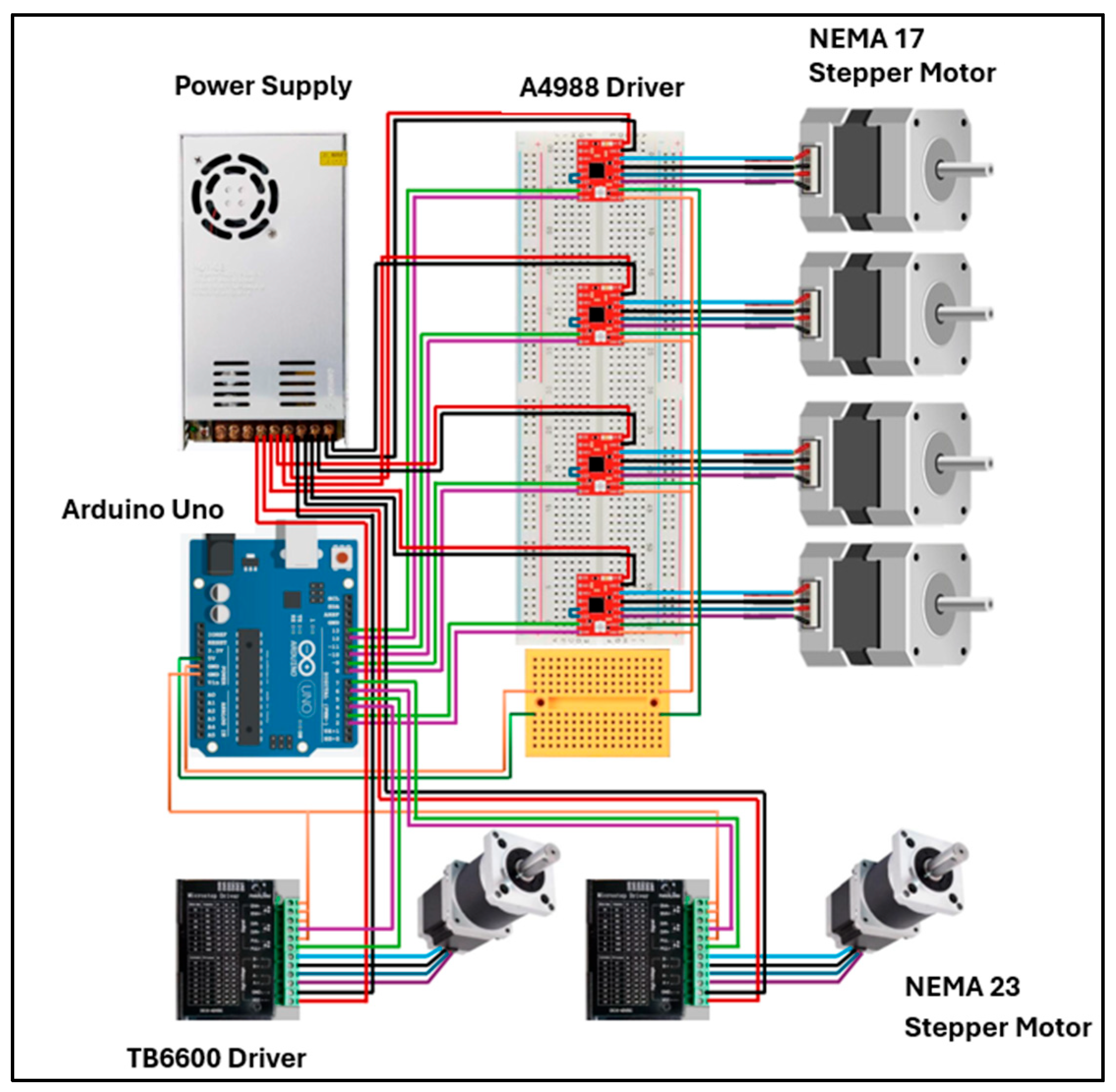
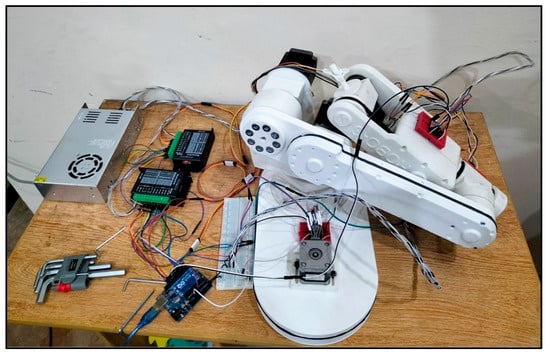
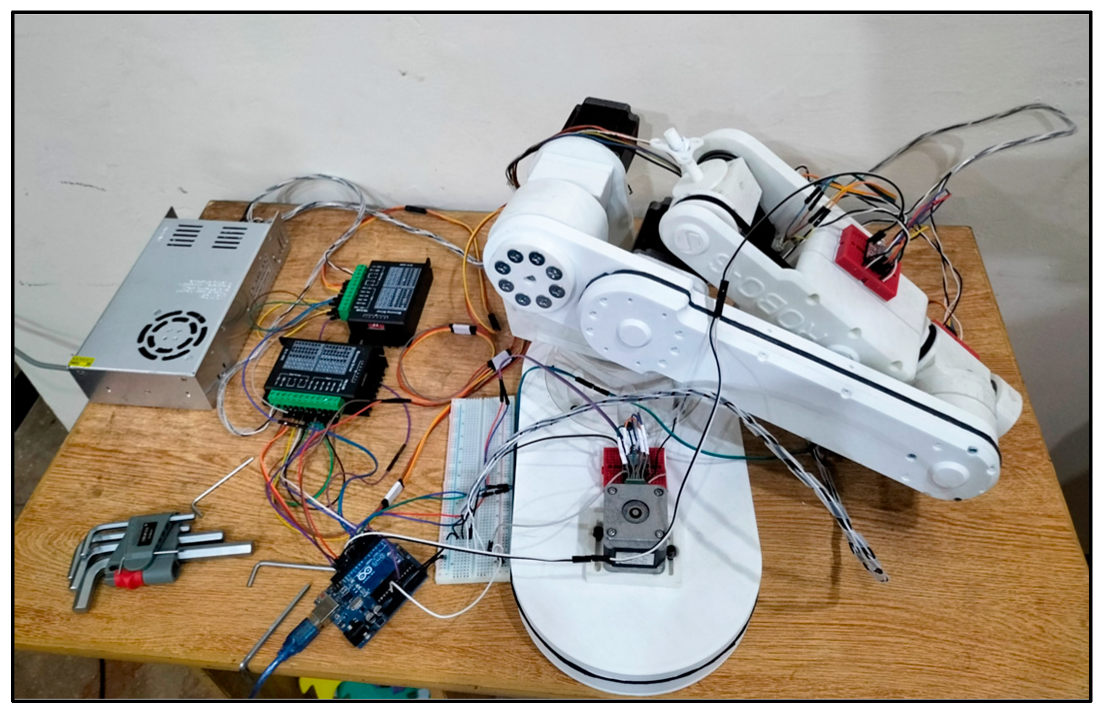
After completing the CAD model, the next step was fabrication of a prototype using 3D printing. Additive manufacturing was selected due to its ease of producing prototypes, intricate geometries, and pieces with high accuracy in short periods. The structural components of ROBO-S were printed using Polylactic Acid (PLA) with an infill density of 20% to ensure the balance between strength, weight, and durability. The printed parts were assembled with all necessary drive components such as motors, bearings, and pulleys, etc. Figure 9 illustrates the 3D-printed components of ROBO-S, showcasing individual parts before assembly and the fully assembled prototype. The schematic and physical layout of the electronic components used in ROBO-S are illustrated in Figure 10 and Figure 11, respectively.
Figure 9.
3D-printed 6-DOF robotic manipulator ROBO-S.
Figure 10.
Hardware schematic of ROBO-S.
Figure 11.
Physical prototype of ROBO-S with integrated electronic components.
4. Results
The performance of the proposed 6-DOF robotic manipulator was evaluated through both MATLAB simulations and hardware implementation. This section discusses the simulation setup, development of the physical prototype, and trajectory tracking results.
4.1. Simulation Workflow
The simulation of the 6-DOF robotic arm, ROBO-S, is carried out in MATLAB Simulink R2021a, integrated with Simscape Multibody for kinematic analysis and mechanical modeling. All simulations are performed on a system equipped with an Intel Xeon quad-core processor and 32 GB of RAM.
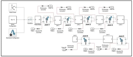
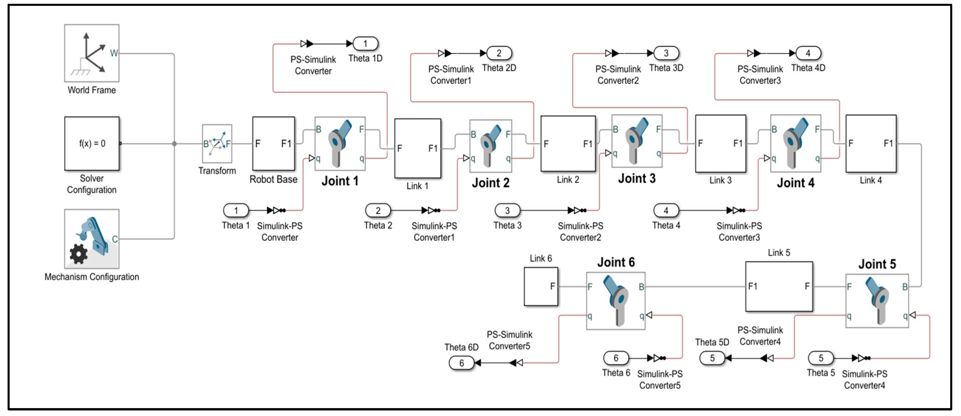
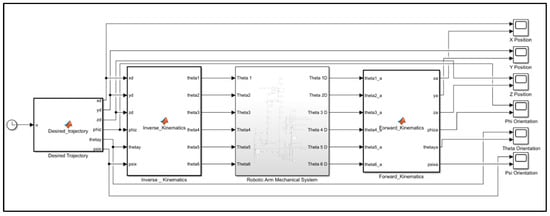
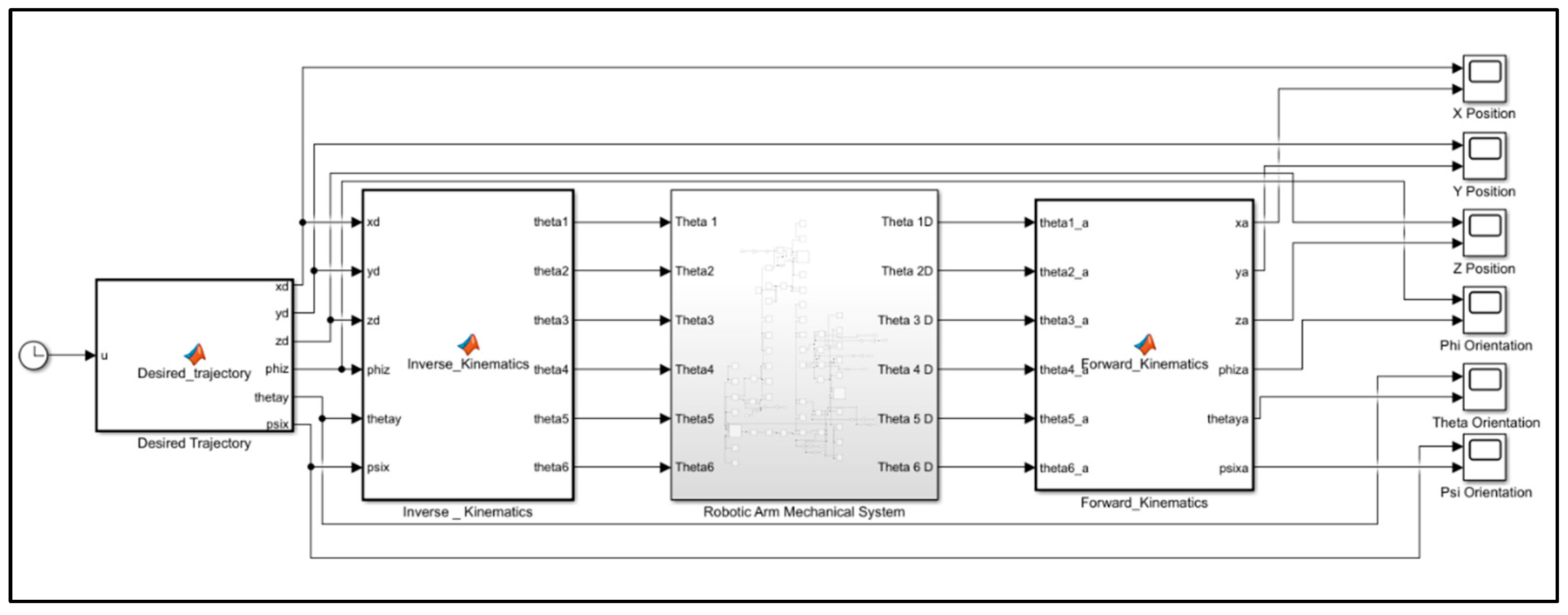
Workflow of the simulation setup of 6-DOF ROBO-S robotic arm in Simulink is described in this section. It begins with a desired trajectory block where predefined equations define the desired 6-DOF trajectory for the robotic arm. The trajectory is then fed into a MATLAB code block for calculating the joint angles required to achieve the desired motion based on inverse kinematics. The calculated joint angles are fed into a Simscape Multibody block that simulates the kinematic behavior of the robotic arm. Finally, the forward kinematics block, also implemented in MATLAB, verifies the final position and orientation of the manipulator’s end effector corresponding to the calculated joint angles. Simscape multibody model and Simulation setup of ROBO-S are shown in Figure 12 and Figure 13, respectively.
Figure 12.
Simscape multibody model of ROBO-S.
Figure 13.
Simulation setup of ROBO-S in MATLAB Simulink.
4.2. Implementation of Inverse Kinematics Model on Prototype
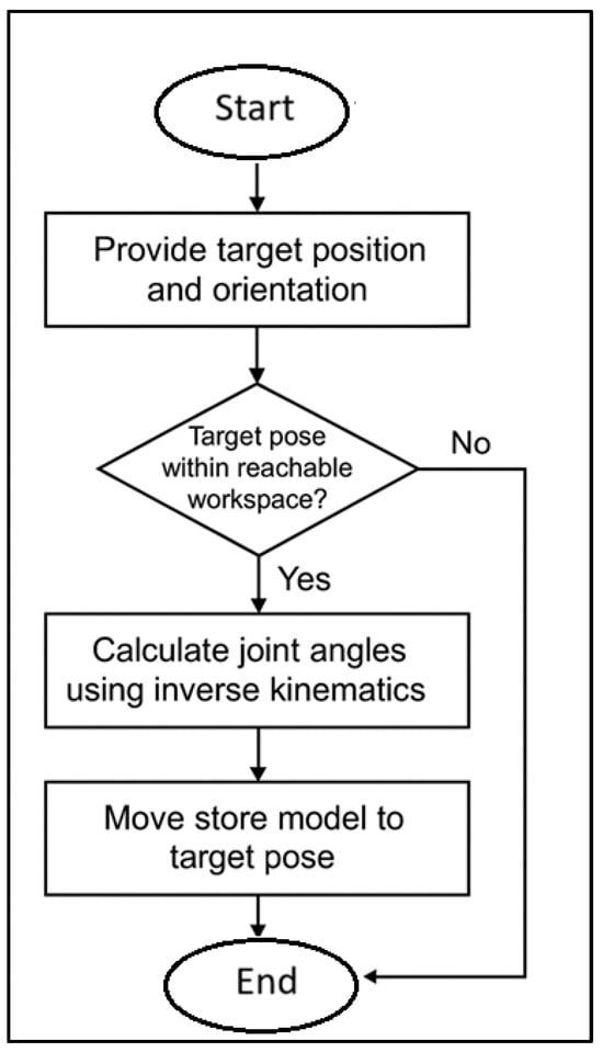
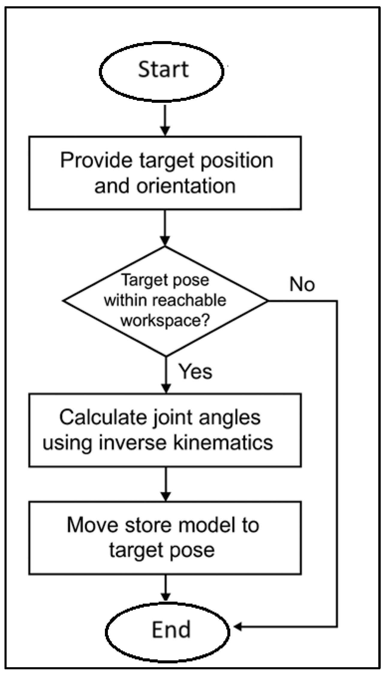
The inverse kinematics (IK) model has been successfully implemented on the ROBO-S robotic arm, where the end-effector is a store model representing the payload. To simulate a store separation trajectory, a target position and orientation based on experimental data was provided by the user. The trajectory planning logic based on inverse kinematics first checks whether the target pose lies within the reachable workspace of the robot. If the target is outside the defined range, the system alerts the user and stops the operation. If it is within reach, the IK model calculates the joint angles needed to position the store model accordingly. These joint angles are then converted into encoder tick values that the motors can interpret. Finally, low-level control logic running on the microcontroller executes these commands, guiding the robotic arm to move the store model smoothly along the desired path. The flowchart for implementing inverse kinematics is given in Figure 14.
Figure 14.
Implementation flowchart of inverse kinematics on ROBO-S robotic arm.
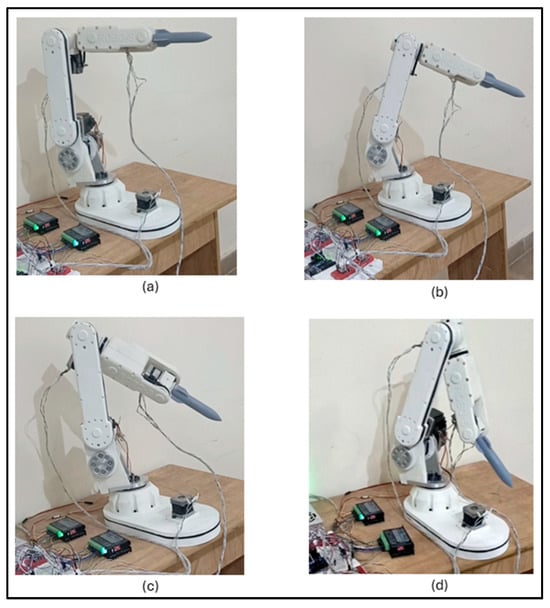
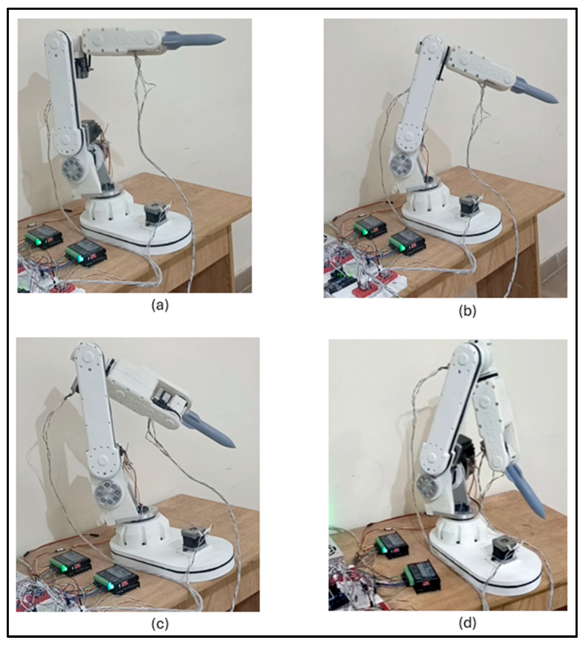
To visualize the implementation of the IK model, the motion of the ROBO-S arm has been broken down into key stages along with the reference store separation trajectory. At each stage, the store model (serving as the end-effector) exhibits a distinct change in position or orientation, such as roll, pitch, or yaw. For instance, Figure 15a shows the initial state of the robotic arm at its home position. Figure 15b,c illustrates the store model undergoing a rolling motion, yawing and pitching actions as given in the input trajectory. The final stage, shown in Figure 15d, demonstrates the store model reaching the terminal point of the trajectory. This sequence effectively demonstrates the robot’s ability to follow a 6-DOF trajectory using the developed IK algorithm.
Figure 15.
Visualization of ROBO-S tracking the reference trajectory over time (a) 0 sec; (b) 0.1 sec; (c) 0.2 sec; (d) 0.3 sec.
4.3. Trajectory Tracking Results
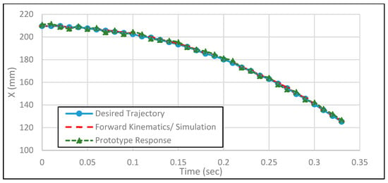
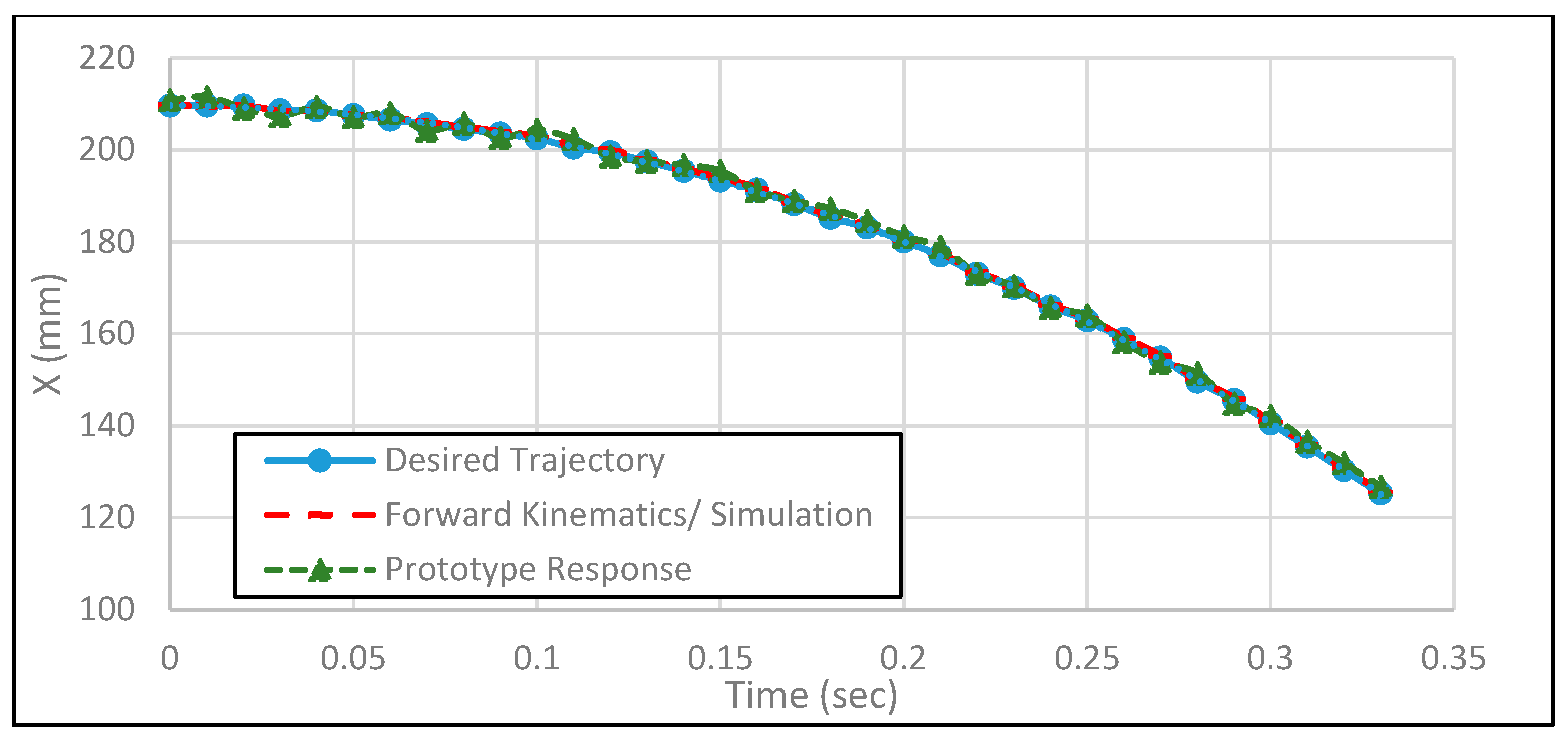
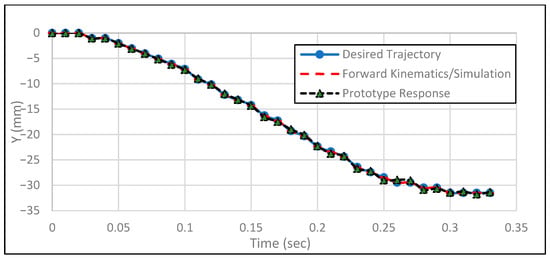
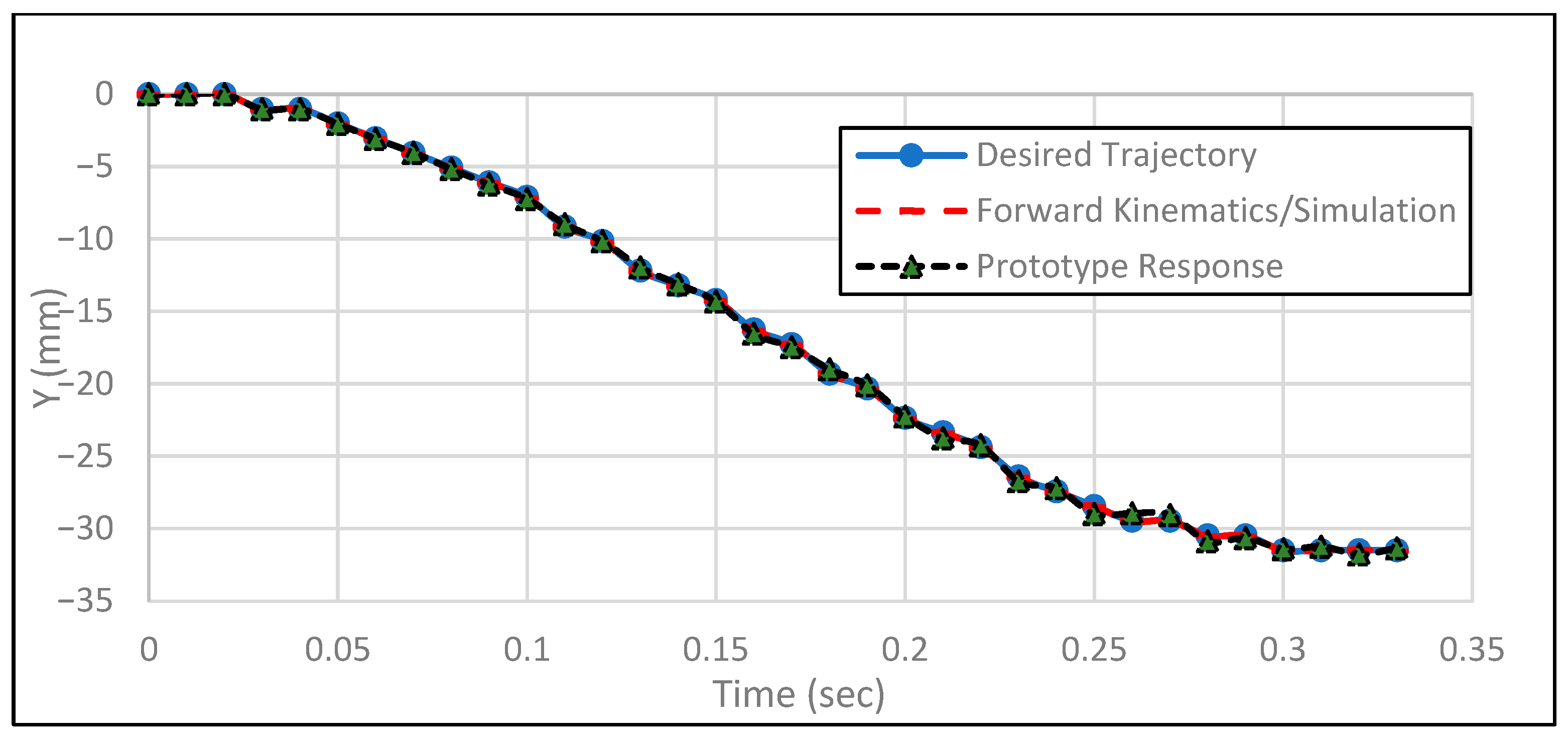
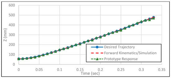
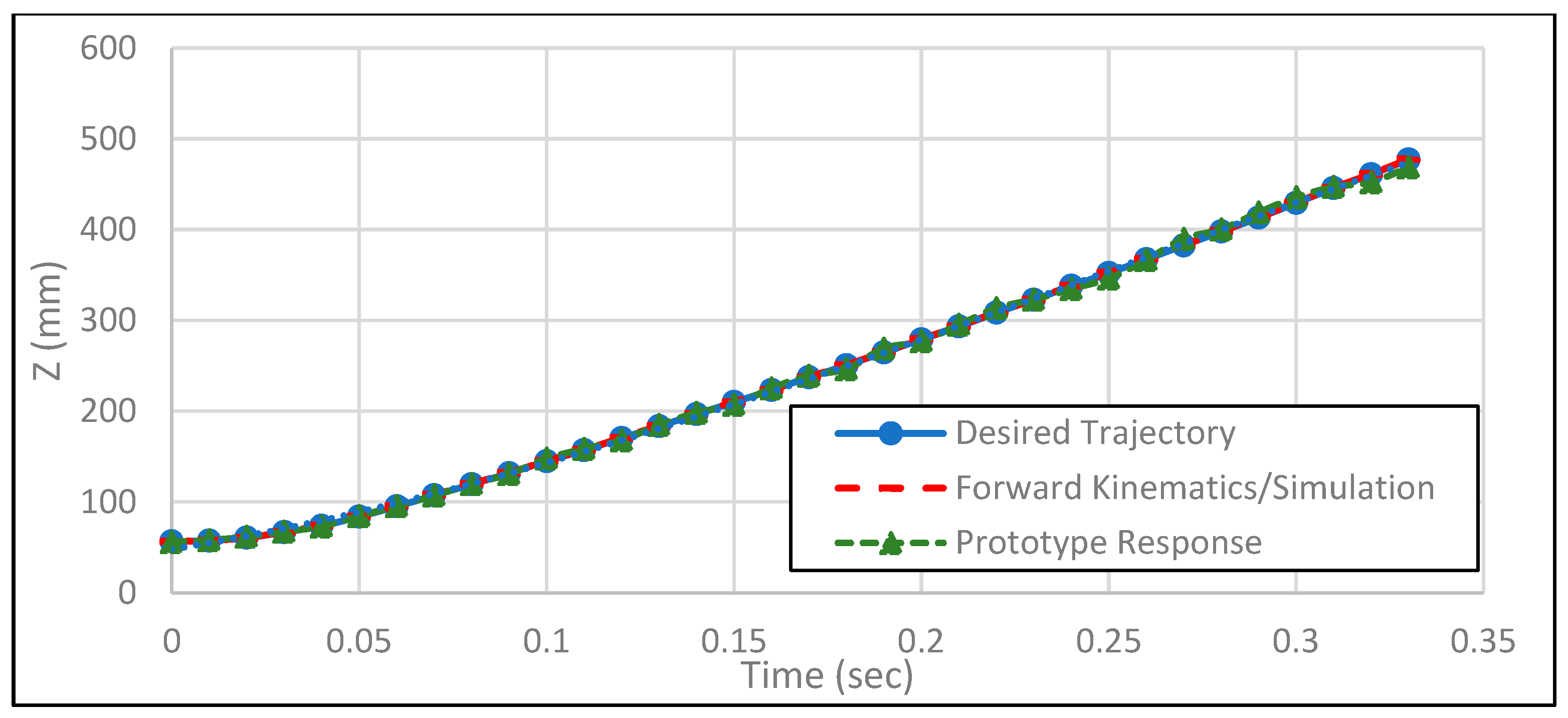
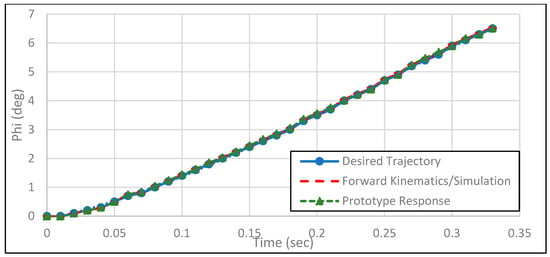
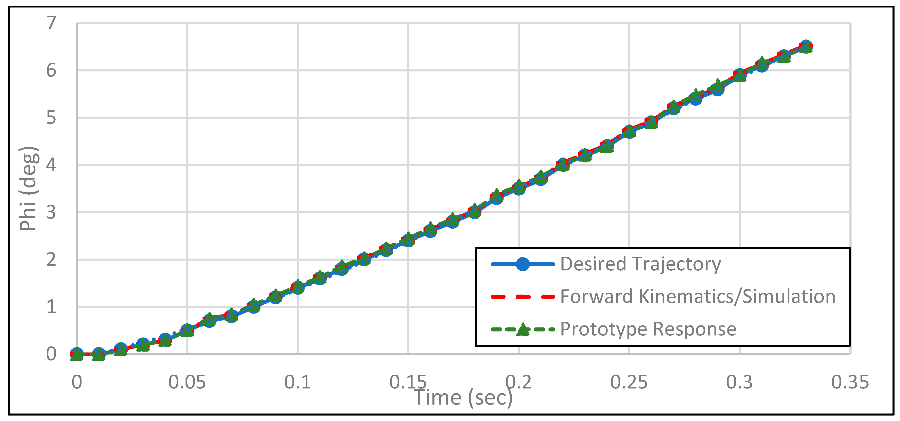
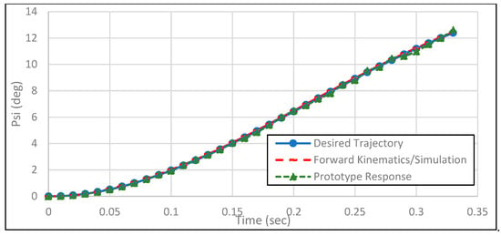
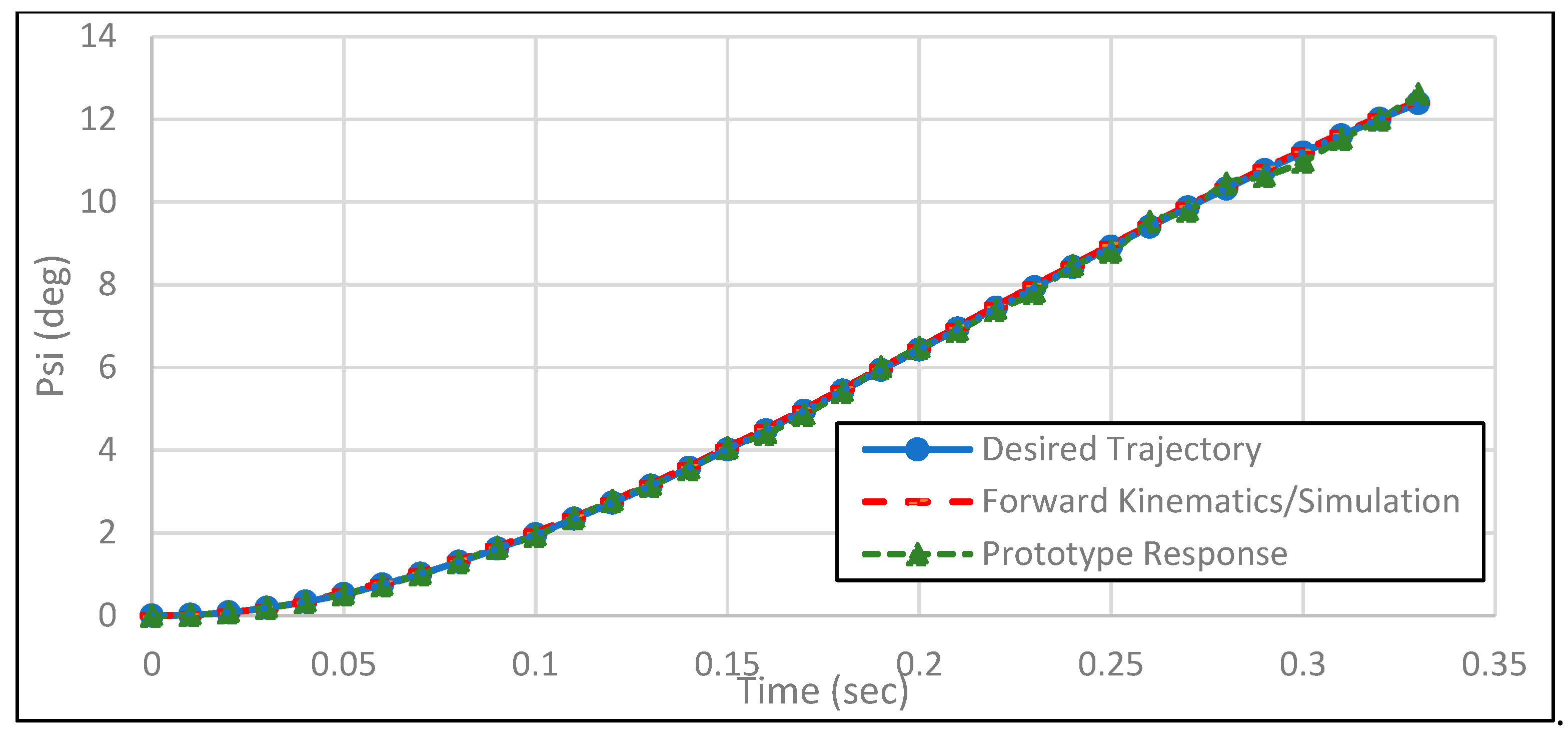
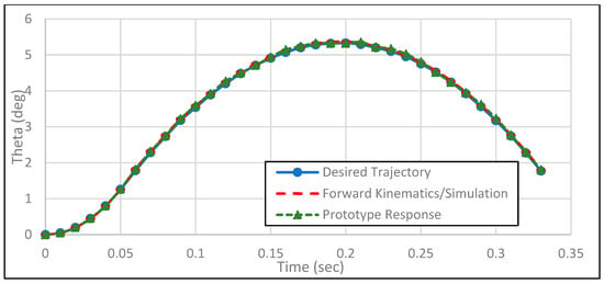
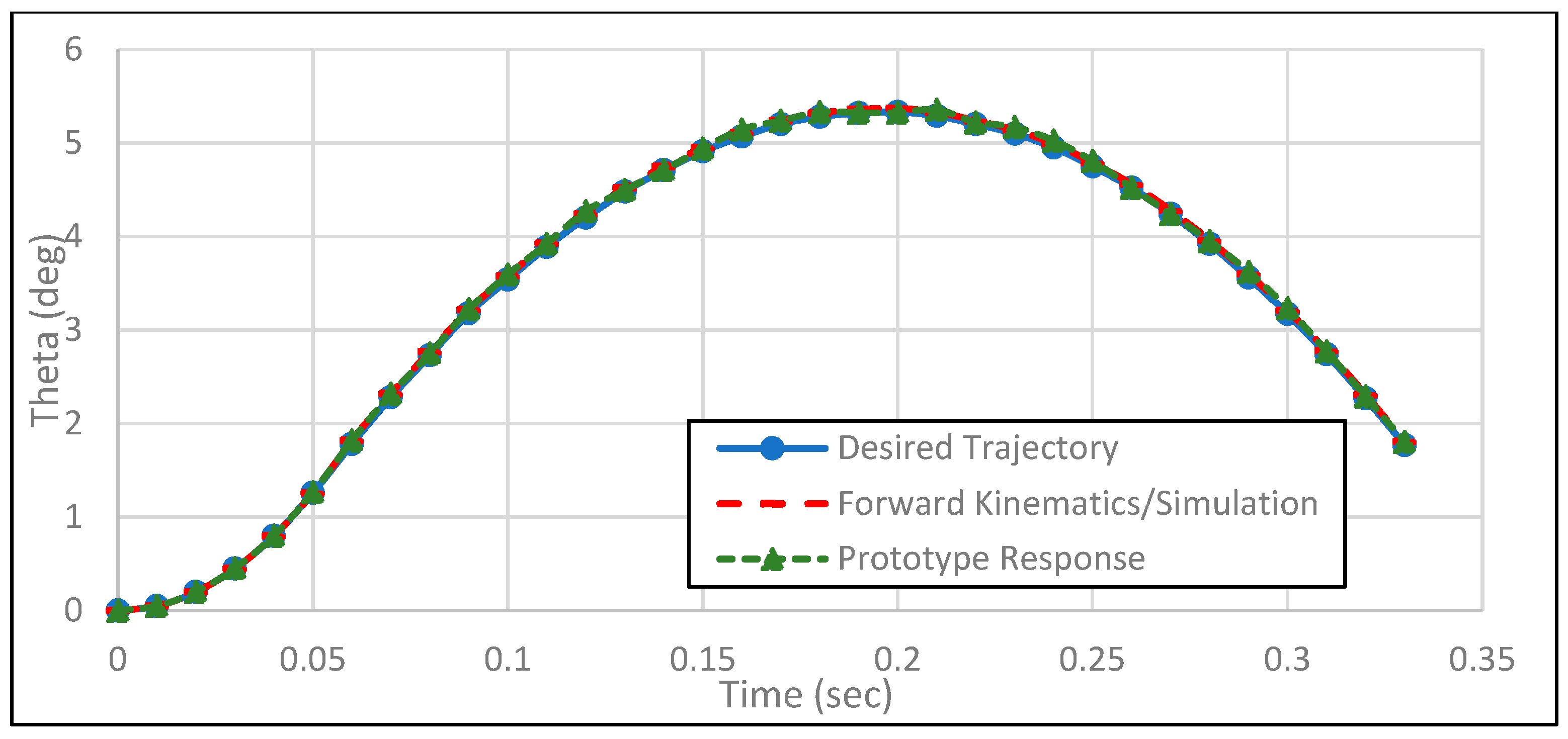
The comparison of results between the desired trajectory, the simulation output (based on forward kinematics), and the actual prototype response is depicted in Figure 16, Figure 17, Figure 18, Figure 19, Figure 20 and Figure 21. Figure 16, Figure 17 and Figure 18 show the position components (x, y, z), while Figure 19, Figure 20 and Figure 21 represent orientation angles (roll, yaw, pitch) which define the rotational part of the 6-DOF trajectory. It is evident that the simulation closely follows the desired trajectory, validating the accuracy of the inverse and forward kinematics algorithms. The prototype response also tracks the desired path with reasonable accuracy, though minor deviations are observed. These discrepancies can be attributed to practical implementation factors such as encoder resolution limits, mechanical tolerances, and nonlinearities in the mapping between joint angles and low-level motor commands.
Figure 16.
Comparison of desired vs. actual horizontal trajectory followed by the robotic arm.
Figure 17.
Comparison of desired vs. actual sideways trajectory followed by the robotic arm.
Figure 18.
Comparison of desired vs. actual vertical trajectory followed by the robotic arm.
Figure 19.
Comparison of desired trajectory and path followed by the robotic arm (roll).
Figure 20.
Comparison of desired trajectory and path followed by the robotic arm (yaw).
Figure 21.
Comparison of desired trajectory and path followed by the robotic arm (pitch).
4.4. Quantitative Performance Evaluation and Repeatability Analysis
To compliment the qualitative trajectory comparisons presented in Figure 16, Figure 17, Figure 18, Figure 19, Figure 20 and Figure 21, a quantitative analysis of the manipulator was carried out. Ten independent runs of the given store separation trajectory were performed with identical operating conditions. Before each run, the robotic arm was returned to its home configuration in order to eliminate bias due to previous motion. During execution, joint encoder readings were recorded and converted to Cartesian position and orientation using the forward kinematics described in Section 3. The reference trajectory was sampled at the controller rate (approximately 100 Hz) and aligned with the measured data before calculating the tracking errors.
4.4.1. Repeatability Analysis
Repeatability was performed using the mean absolute tracking error (μ), standard deviation (σ), and coefficient of variation (CV):
The statistical results obtained from ten independent runs are summarized in Table 4.
Table 4.
Summary of statistical results obtained from 10 runs.
The obtained coefficient of variation was below 0.75% for position components and below 1% for orientation components.
4.4.2. Tracking Performance Metrics
Root Mean Square Error (RMSE), Integral Absolute Error (IAE), Integral Square Error (ISE), and Integral Time Absolute Error (ITAE) were used as tracking performance metrics and given in Table 5.
where is the difference between desired and measured trajectory states.
Table 5.
Trajectory tracking performance indices.
4.4.3. Motion Smoothness
Motion smoothness indicators evaluated using velocity variation and jerk magnitude are shown in Table 6.
Table 6.
Motion Smoothness Indicators.
5. Discussion
The results presented in Section 4 explicitly addresses the research questions defined in the introduction section. As for RQ1, the close agreement between the desired trajectory and the simulation results demonstrates that a serial 6-DOF robotic manipulator can be kinematically designed by using closed-form forward and inverse kinematics and the kinematics formulation is able to satisfy the workspace and motion requirements of CTS based store separation trajectory tracking. Addressing RQ2, the simulation results show that the derived kinematic model can accurately track experimentally obtained 6-DOF store separation trajectories in a simulation environment. Both translational and rotational components follow the given reference. In response to RQ3, the physical prototype implementation demonstrate that the derived kinematic framework can be implemented on real hardware successfully and can achieve consistent trajectory tracking performance under practical constraints. Although minor deviations are observed in the desired and actual prototype trajectories, these differences are attributed to encoder resolution limits, mechanical tolerances, and nonlinearities in the mapping between joint angles and low-level motor commands which are inherent in experimental robotic systems. It is important to note that these deviations do not indicate a limitation of the kinematic formulation but rather confirm that the proposed method remains robust under realistic operating conditions. In addition, a quantitative evaluation was performed through multiple independent executions of the same motion. The repeatability statistics and tracking error metrics show that the deviations are small and consistent across runs. The smoothness indicators also suggests continuous motion without sudden disturbances.
To further contextualize the proposed framework within the current research landscape, a comparison with representative CTSs is presented in Table 7.
Table 7.
Comparison of the proposed framework with state-of-the-art CTS and robotic wind-tunnel trajectory execution approaches.
Table 7 presents a comparison between the proposed robotic framework and various representative CTS approaches presented in the recent literature. The CTS reported in [16] involves a 3-DOF manipulator and determines the required motion by using numerical inverse kinematics. However, the work mainly focuses on mechanical feasibility and provides only limited evaluation of trajectory tracking accuracy. In contrast, this study involves a full 6-DOF serial manipulator and derives an explicit analytical formulation for forward and inverse kinematics which allows direct computation of the required trajectory.
The CTS design framework described in [17] focuses on the development of system-level methodologies for designing CTS mechanisms used in wind-tunnel testing. In those systems the motion of the store model is generally reproduced using mechanical rigs integrated within the facility. Although such arrangements are suitable for aerodynamic experiments, they do not provide a generalized robotic modeling methodology for trajectory generation. The present work provides a clearly defined kinematic formulation allowing the trajectory to be computed and executed in a systematic manner.
An aircraft manipulator system presented in [18] applies numerical inverse kinematics combined with PID control in a simulation environment and studies simplified aircraft motion dynamics. On the other hand, the current study includes prototype development and experimental implementation to evaluate trajectory tracking performance using quantitative metrics and repeatability statistics.
Similarly, the semi-CTSs reported in [36] reproduce store trajectories through mechanical actuation of facility-specific rigs. Although these systems are effective for aerodynamic investigations, they lack a generalized robotic trajectory execution framework. Another alternative architecture is the wire driven parallel robot proposed in [37], which focuses on cable-driven kinematic modeling and workspace analysis for wind-tunnel positioning tasks. These systems can offer large workspaces but their actuation and control principles are different from the serial manipulator configuration presented in current work. The proposed ROBO-S framework differs from previous approaches by combining a full 6-DOF robotic manipulator with an analytical kinematic formulation and prototype-level experimental validation. This provides a transparent and reproducible framework for accurate execution of CTS store separation trajectories in wind-tunnel testing.
6. Conclusions
This study presented the design, modeling, and experimental implementation of the ROBO-S robotic framework for executing Captive Trajectory System (CTS) store separation trajectories. The work mainly focused on developing a systematic kinematic formulation for a 6-DOF serial manipulator capable of tracking store separation trajectories. Forward and inverse kinematic relations were derived using the DH representation and geometric analysis respectively. The proposed framework was first examined in simulation and then implemented on a laboratory-scale robotic prototype to demonstrate practical trajectory execution.
The obtained results show that the manipulator is able to track the desired 6-DOF store motion in a stable and consistent manner. The simulated and experimental trajectories follow the prescribed reference with small deviations. In addition, quantitative indicators such as RMSE, tracking error indices, and repeatability statistics were used to evaluate the motion tracking behavior. These metrics indicate that the proposed framework provides reliable trajectory reproduction for CTS store separation applications. Some limitations should also be noted. The present work mainly addresses kinematic modeling and trajectory tracking and does not explicitly include dynamic effects such as inertia, actuator dynamics, or aerodynamic loading. Also, the experimental validation was performed on a laboratory prototype. Practical factors like encoder resolution, mechanical tolerances, and actuator nonlinearities can introduce small differences between desired and measured trajectories. Future work will focus on incorporating dynamic modeling and more advanced control strategies. Real-time load aware control and force feedback can also be considered. Additional validation under actual wind-tunnel operating conditions will be important to further examine the applicability of the proposed system for practical CTS-based aerodynamic testing.
Author Contributions
Conceptualization, S.S. and M.U.S.; methodology, S.S.; software, S.S.; validation, S.S., M.U.S. and F.K.U.; formal analysis, S.S.; investigation, S.S.; resources, S.S. and F.K.U.; data curation, S.S.; writing—original draft preparation, S.S., M.W. and Z.K., writing—review and editing, S.S., M.W. and Z.K., visualization, S.S. and M.W.; supervision, M.U.S. and F.K.U.; project administration, M.U.S. and Z.K. All authors have read and agreed to the published version of the manuscript.
Funding
This research received no external funding.
Data Availability Statement
The data presented in this study are available on request from the corresponding author.
Conflicts of Interest
The authors declare no conflict of interest.
Abbreviations
The following abbreviations are used in this manuscript:
| CTS | Captive Trajectory System |
| DH | Denavit–Hartenberg |
| DOF | Degrees of Freedom |
| ai | The offset distance between adjacent joint axes |
| di | The translational distance between incident normals |
| Joint Angle | |
| Twist Angle | |
| Psi | Yaw Angle |
| Theta | Pitch Angle |
| Phi | Roll Angle |
References
- Craig, J.J. Introduction to Robotics: Mechanics and Control, 3rd ed.; Pearson Prentice Hall: Upper Saddle River, NJ, USA, 2005. [Google Scholar]
- Spong, M.W.; Hutchinson, S.; Vidyasagar, M. Robot Modeling and Control, 1st ed.; John Wiley & Sons: New York, NY, USA, 2005. [Google Scholar]
- Iqbal, J.; Islam, M.R.U.; Khan, H. Modeling and analysis of a 6 DOF robotic arm manipulator. Can. J. Electr. Electron. Eng. 2012, 3, 300–306. [Google Scholar]
- Kumar, K.K.; Srinath, A.; Jugalanvesh, G.; Premsai, R.; Suresh, M. Kinematic analysis and simulation of 6 DOF Kuka KR5 robot for welding application. Int. J. Eng. Res. Appl. 2013, 3, 820–827. [Google Scholar]
- Singh, E.H.; Dhillon, N.; Ansari, E.I. Forward and inverse kinematics solution for six DOF with the help of robotics toolbox in MATLAB. Int. J. Appl. Innov. Eng. Manag. 2015, 4, 17–22. [Google Scholar]
- Alwardat, M.Y.; Alwan, H.M. Forward and Inverse Kinematics of a 6-DOF Robotic Manipulator with a Prismatic Joint Using MATLAB Robotics Toolbox. Int. J. Adv. Technol. Eng. Explor. 2024, 11, 1096–1110. [Google Scholar] [CrossRef] [Scilit]
- Stahl, W. Experimental Investigation of Store Separation Using CTS; AGARD Report No. AGARD-AR-330; NATO Science and Technology Organization: Neuilly-sur-Seine, France, 1995. [Google Scholar]
- Tomaro, R.F.; Smith, T.R.; Johnson, W.R. A Solution on the F/A-18C for Store Separation Using Wind Tunnel Testing. In Proceedings of the AIAA Aerospace Sciences Meeting and Exhibit, Reno, NV, USA, 11–14 January 1999. AIAA Paper 99-0122. [Google Scholar]
- Andrew, G.; Jay, N.; Roman, P. Design & Development of a New Captive Trajectory Simulation Model Support System. In Proceedings of the 35th Joint Propulsion Conference and Exhibit, Los Angeles, CA, USA, 20–24 June 1999. [Google Scholar]
- Garçon, F.; Taravel, P.; Raffin, J.-C. Recent Developments in Captive Trajectory Systems of the ONERA Modane Wind Tunnels. In Proceedings of the 39th Aerospace Sciences Meeting and Exhibit, Reno, NV, USA, 8–11 January 2001. [Google Scholar]
- Navair, A.C.; Md, P.R. Lessons Learned in 30 Years of Store Separation Testing. In Proceedings of the 47th AIAA Aerospace Sciences Meeting including The New Horizons Forum and Aerospace Exposition, Orlando, FL, USA, 5–8 January 2009. [Google Scholar]
- Carter, R.; Lind, R. Trajectory Optimization for Guided Store Separation. In Proceedings of the AIAA Guidance, Navigation, and Control Conference, Minneapolis, MN, USA, 13–16 August 2012. [Google Scholar]
- Huang, X.H.; Pang, X.D. Development of a New CTS System in a 1.2 m Transonic Wind Tunnel. J. Exp. Fluid Mech. 2008, 22, 95–98. [Google Scholar]
- Huang, X.H.; Luo, X.F. Design & Development of CTS System in FL-24 Wind Tunnel. Acta Aerodyn. Sin. 2008, 26, 145–149. [Google Scholar]
- Zhou, R.; Huang, X.; Zhang, Z.; Li, P. A captive trajectory system using double closed-loop velocity control. Acta Aeronaut. Astronaut. Sin. 2014, 35, 1522–1529. [Google Scholar] [CrossRef]
- Ran, W.; Binghui, C.; Jun, Z.; Chuanbao, S.; Xinlin, W. The design of a 3-DOF robot arm used for captive trajectory simulation in wind tunnel test. J. Exp. Fluid Mech. 2016, 30, 91–97. [Google Scholar]
- He, Y.; Zhang, F.L.; Xu, Z.G.; Liu, Z. Design Method of CTS for Wind Tunnel Experiment. Acta Armamentarii 2018, 39, 2480–2487. [Google Scholar] [CrossRef]
- Ishola, A.A.; Whidborne, J.F.; Tang, G. An Aircraft-Manipulator System for Virtual Flight Testing of Longitudinal Flight Dynamics. Robotics 2024, 13, 179. [Google Scholar] [CrossRef] [Scilit]
- Liu, C.K.; Negrut, D. The role of physics-based simulators in robotics. Annu. Rev. Control Robot. Auton. Syst. 2021, 4, 35–58. [Google Scholar] [CrossRef] [Scilit]
- Parhi, D.R.; Deepak, B.B.; Nayak, D.; Amrit, A. Forward and inverse kinematic models for an articulated robotic manipulator. Int. J. Artif. Intell. Comput. Res. 2012, 4, 103–109. [Google Scholar]
- Kucuk, S.; Bingul, Z. Robot Kinematics: Forward and Inverse Kinematics; IntechOpen: London, UK, 2006. [Google Scholar]
- Denavit, J.; Hartenberg, R.S. A kinematic notation for lower-pair mechanisms based on matrices. J. Appl. Mech. 1955, 22, 215–221. [Google Scholar] [CrossRef] [Scilit]
- Pieper, D.L. The Kinematics of Manipulators Under Computer Control. Ph.D. Dissertation, Stanford University, Stanford, CA, USA, 1968. [Google Scholar]
- Freudenstein, F. Design of mechanisms. Annu. Rev. Fluid Mech. 1973, 5, 457–486. [Google Scholar]
- Chen, P.; Liu, L.; Yu, F.; Li, H.; Yang, F.; Wang, X. A geometrical method for inverse kinematics of a kind of humanoid manipulator. Robot 2012, 34, 211. [Google Scholar] [CrossRef] [Scilit]
- Qassem, M.A.; Abuhadrous, I.; Elaydi, H. Modeling and simulation of 5 DOF educational robot arm. In Proceedings of the 2010 2nd International Conference on Advanced Computer Control, Shenyang, China, 27–29 March 2010; pp. 569–574. [Google Scholar]
- Wen, S.; Qin, G.; Zhang, B.; Lam, H.K.; Zhao, Y.; Wang, H. The study of model predictive control algorithm based on the force/position control scheme of the 5-DOF redundant actuation parallel robot. Robot. Auton. Syst. 2016, 79, 12–25. [Google Scholar] [CrossRef] [Scilit]
- Filiposka, M.; Djuric, A.M.; Elmaraghy, W. Kinematic analysis of a 6 DOF gantry machine. In SAE 2015 World Congress & Exhibition; SAE International: Warrendale, PA, USA, 2015; pp. 1–7. [Google Scholar]
- Chen, Q.; Zhu, S.; Zhang, X. Improved inverse kinematics algorithm using screw theory for a six-DOF robot manipulator. Int. J. Adv. Robot. Syst. 2015, 12, 140. [Google Scholar] [CrossRef] [Scilit]
- Raouf, I.; Lee, H.; Kim, H.S. Deep learning-based fault diagnosis of servo motor bearing using the attention-guided feature aggregation network. Expert Syst. Appl. 2024, 258, 125137. [Google Scholar] [CrossRef] [Scilit]
- Raouf, I.; Lee, H.; Kim, H.S. Mechanical fault detection based on machine learning for robotic RV reducer using electrical current signature analysis: A data-driven approach. J. Comput. Des. Eng. 2022, 9, 417–433. [Google Scholar] [CrossRef] [Scilit]
- Izaz, R.; Hyewon, L.; Yeong Rim, N.; Byeng, D.Y.; Heung Soo, K. Prognostic Health Management of the robotic Strain-Wave Gear Reducers based on variable speed of operation. J. Comput. Des. Eng. 2022, 9, 1775–1788. [Google Scholar]
- Izaz, R.; Prashant, K.; Salman, K.; Kim, H.S. Comprehensive Analysis of Current Developments, Challenges and Opportunities for Health Assessment of Smart Factory. Int. J. Precis. Eng. Manuf.-Green Tech. 2025, 12, 1321–1338. [Google Scholar]
- Fox, J.H. Generic Wing, Pylon, and Moving Finned Store; Technical Report No. TN 37389-6001; Arnold Engineering Development Center (AEDC): Tullahoma, TN, USA, 2000; pp. 535–554.
- Erdman, A.G. Mechanism Design and Synthesis, 2nd ed.; Prentice Hall: Englewood Cliffs, NJ, USA, 1991; Volume 1. [Google Scholar]
- Robertson, G.; Kumar, R. A Semi-Captive Trajectory System for the FSU Polysonic Wind Tunnel. In Proceedings of the 2018 AIAA Aerospace Sciences Meeting, AIAA 2018-0330, Kissimmee, FL, USA, 8–12 January 2018. [Google Scholar]
- Ji, Y.; Peng, M.; Lin, Q. Design of a wire-driven parallel robot for wind tunnel test based on the analysis of stiffness and workspace. Robotica 2024, 42, 3380–3397. [Google Scholar] [CrossRef] [Scilit]





Disclaimer/Publisher’s Note: The statements, opinions and data contained in all publications are solely those of the individual author(s) and contributor(s) and not of MDPI and/or the editor(s). MDPI and/or the editor(s) disclaim responsibility for any injury to people or property resulting from any ideas, methods, instructions or products referred to in the content. |
© 2026 by the authors. Licensee MDPI, Basel, Switzerland. This article is an open access article distributed under the terms and conditions of the Creative Commons Attribution (CC BY) license.