


Abstract
Cooperative cognitive radio networks (CCRANs) not only improve spectrum utilization efficiency by sharing spectrum resources between primary and secondary systems but also expand wireless coverage by relay cooperative communications, while UAV communication is a crucial supporting technology for the low-altitude economy. Conventional single-antenna rate-splitting multiple access (RSMA)-enabled CCRAN can only benefit from the power resource allocation and the associated system performance is limited. Against this background, a multi-antenna RSMA and UAV-enabled CCRAN is examined to improve the network transmission capability, and a two-phase communication protocol with scalable transmission duration is established to coordinate the information transmission between the primary and secondary systems. Consequently, two additional degrees of freedom (DoFs) of space and time resources are utilized in the proposed system as compared with conventional single-antenna CCRANs. To accomplish the system design, we formulate a non-convex optimization problem and derive the associated iterative algorithm based on successive convex approximation. Simulation results show that the proposed scheme can significantly enhance the system’s transmission capability.
1. Introduction
Relay cooperative communication is an effective technology for eliminating coverage blind spots or enhancing radio communication links in modern wireless networks. Traditionally, relays are implemented by communication users or dedicated devices that do not have their own data to transmit [1,2,3,4,5]. The cooperative cognitive radio network (CCRAN) is another form of cooperative communication system for extending wireless coverage or enhancing wireless transmission links, where the cooperative relay is undertaken by the cognitive transceivers. Compared with traditional relay cooperative communications, cognitive relays of the CCRANs not only need to forward primary data but also have their own data to transmit [6,7,8]. In the CCRANs, the primary systems extend the transmission range or enhance the remote transmission links, while the cognitive system gains spectrum access authorization, therefore achieving a win–win situation.
Most existing CCRANs are terrestrial networks, and the wireless coverage capability of the terrestrial relays is usually limited, which restricts the application of the cooperative cognitive wireless networks. As compared with terrestrial relay communications, unmanned aerial vehicle (UAV) communications are less limited by geographical conditions [9,10,11], and therefore can benefit from the line-of-sight (LOS) transmissions as well as the flexible deployments that make them particularly suitable for air–ground cooperative cognitive wireless networks [12,13] and the maritime cognitive radio network [14].
The air–ground CCRAN in [12] includes a ground base station, a ground unmanned vehicle, and cognitive UAV swarms. The base station aims to send authorized data to the ground unmanned vehicle and cognitive common data to the UAV swarms. The system considers the situation where the transmission between the base station and the ground unmanned vehicle is blocked and some unmanned aerial vehicles cannot correctly demodulate the common data. In order to accomplish information transmission, the authors proposed a two-phase transmission protocol. In the first phase, the ground base station sends the authorized data and the cognitive common data to the UAV swarms at the same time. In the second stage, one of the UAVs forwards the received (in amplify and forward mode) or demodulated (in decode and forward mode) authorized data and the cognitive common data to the ground unmanned vehicle and the remaining UAVs that cannot correctly demodulate the common data, respectively.
The authors of [13] considered another air–ground cooperative cognitive wireless network, where the primary system includes a ground PT and a ground PR, and the cognitive system consists of a UAV and a ground secondary user (SU). Similar to the air–ground CCRAN [12], the transmission link between the PT and PR is blocked. The authors designed a two-phase transmission protocol to achieve cooperative cognitive communications. In the first phase, the PT sends the primary data to the UAV, and in the second phase, the UAV superimposes the demodulated primary data and its own data and sends them to the PR and SU, respectively. Since the CCRANs of [12,13] are both single-antenna networks, the systems therein use power domain non-orthogonal multiple access (P-NOMA) to achieve the multiplexed transmissions of the primary and secondary data.
In addition to the NOMA, rate-splitting multiple access (RSMA), a more powerful multiple access technique [15], was also used to facilitate the realization of the CCRAN. In the same network setup and an identical transmission protocol to [13], ref. [16] used the RSMA to replace the P-NOMA in the second transmission phase to further improve the access capability. In a similar network setup and transmission protocol as [13,16] with the exception that the direct communication link between the PT and PR exists, [17] used the RSMA to enhance the primary transmission rather than to accomplish the primary transmission. Note that both RSMA-enabled CCRANs [16,17] are single-antenna systems and only the power resource can be utilized. Consequently, both the network access capability and the system performance are severely limited. In addition, the two transmission phases therein are equal in length and the associated transmission protocol cannot adapt to the possible different transmission requirements between the primary and secondary systems.
In multi-user wireless communications, when the transmitter is equipped with multiple antennas, spatial division multiple access (SDMA) is usually used to facilitate the system’s implementation [18,19,20]. In the SDMA-enabled multiple-antenna communication systems, inter-user interference is treated as noise, thereby limiting the system performance improvement to a certain extent. As one of the key technologies of 6G, the RSMA has better interference management capabilities than the SDMA. It divides the transmission data of each user into public and private streams, encoding and beamforming them separately, and therefore, the receivers can use interference cancellation to enable the private streams to avoid interference from the public streams [21,22,23].
Given these advantages, RSMA has also been widely applied in traditional relay cooperative communication systems to enhance the remote transmission links [24,25,26,27]. These relay cooperation systems are based on the same working principles where the systems divide users into near-end and far-end users and divide the transmissions into two time slots. The first time slot is the direct transmission phase, where all users, including the near-end and far-end users, receive the public and private data transmitted by the base station (BS). The second time slot is the relay forwarding phase, where the near-end user forwards the decoded public data to the far-end user. Therefore, the far-end user can combine the public data received in the first and second phases to enhance the received signal. In these relay cooperative systems, each system has its own particular characteristic. For example, [24] added cooperative jamming to improve the security of the information transmission, while [25,26,27] adopted coordinated multi-point, intelligent reflecting surface, and relay selection to further enhance the system’s transmission capability, respectively.
According to the previous description, UAV-assisted air–ground CCRANs possess unique advantages in improving spectrum efficiency and expanding radio coverage, especially in achieving blind spot coverage. However, existing air–ground CCRANs are all single-antenna-based and cannot utilize the spatial degrees of freedom provided by multiple antennas to enhance the transmission capabilities. In view of this, this article considers a multi-antenna air–ground CCRAN and proposes an RSMA-enhanced cooperative scheme to achieve the direct transmission of the near-end PRs, the cooperative transmission of the far-end PR in the blind spot, and the direct transmission of the SR. In order to implement this scheme, a two-phase transmission protocol is designed. In the first phase, the PT uses RSMA to send the near-end user data and the far-end user data to the near-end PRs and the cognitive UAV, respectively. The near-end PRs demodulate the data sent to them, while the cognitive UAV demodulates the data sent to the far-end PR. In the second phase, the cognitive UAV first employs RSMA to superimpose the demodulated far-end user data in the first stage and the cognitive data, and then send them to the far-end PR and the CR, respectively.
In order to further improve the transmission performance, time allocation between the two transmission phases is included in the system design to meet the different transmission requirements of the primary and secondary systems. To ensure the system operates in its optimal state, the design variables including the transmitted beamforming vectors, the time allocation variable, and the data rate allocation variables in the two transmission phases should be optimized. To this end, we formulate a power minimization problem subject to the PT and SR transmission rate constraints. The optimization problem is shown to be non-linear and non-convex, and to solve it, an iterative solution algorithm is derived based on successive convex approximation (SCA).
It should be emphasized that the proposed RSMA-enhanced air–ground CCRAN scheme differs from the RSMA-enhanced ground cooperative communication systems [24,25,26,27] in three aspects. (1) The traditional relay cooperation networks are homogeneous and only involve a single system, and in the cooperative forwarding phase, the near-end user does not have its own data to transmit and only acts as a relay, so RSMA is not needed again; meanwhile, the proposed air–ground CCRAN consists of both the primary and secondary systems, so in the cooperative forwarding phase, the UAV not only needs to forward the remote PR’s data but also needs to send their own data. (2) In traditional relay cooperative networks, the transmission link between the transmitter and the remote user exists, and the near-end user only forwards the decoded public data to the remote user to enhance the remote user’s data transmission capability, whereas in the proposed air–ground CCRAN, the transmission link between the PT and the remote PR is blocked, and the information transmission between them can only rely on the UAV’s cooperative forwarding. (3) Most traditional relay cooperation networks do not consider the time allocation between the two transmission phases. This article further considers the time allocation issue, and the introduction of RSMA and rate allocation variables in the forwarding phase makes the optimization problem more involved than the conventional one.
Due to the multi-antenna RSMA and the scalable transmission duration between the two phases, the proposed scheme is also different from the single-antenna RSMA and equal-length transmission phase schemes [16,17]. In [16,17], only the power resource can be utilized and optimized, while in our work, two additional degrees of freedom (DoFs) of space and time resources are used and optimized. For this very reason, not only the network transmission capabilities but also the optimization modeling and the associated solving methods between [16,17] and our work are fundamentally different. Our work greatly improves the network transmission capability at the expense of more involved optimization problem modeling and solving methods.
Notations: is the set of complex matrices of order ; is the positive semidefinite matrix; , , and are the conjugate transpose, the trace, and rank of matrix , respectively; is the circularly symmetric complex gaussian stochastic variable with zero mean and covariance . is the modulo 2 operation.
2. System Model
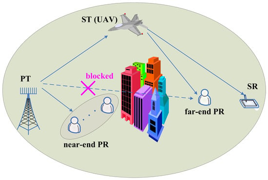
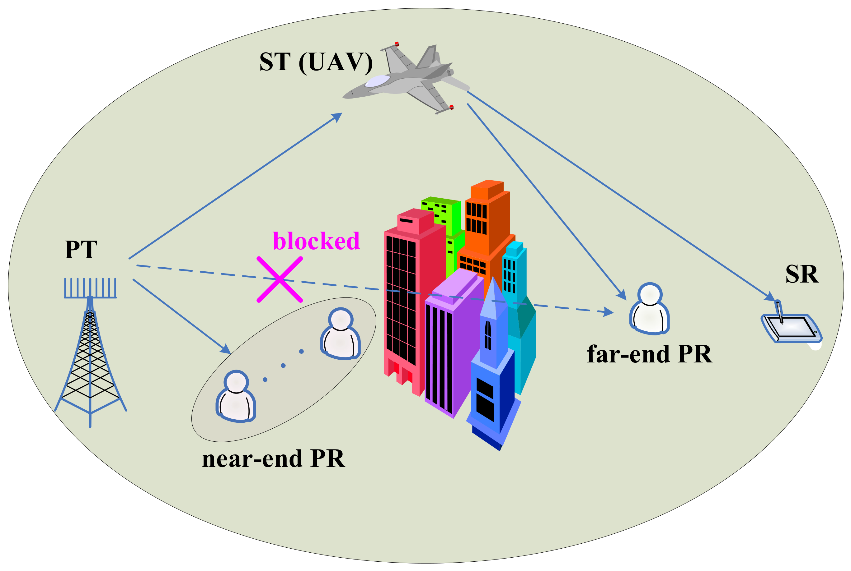
As shown in Figure 1, the considered CCRAN consists of a terrestrial primary system and an aerial cognitive system. The primary system includes a PT and K PRs, among which are the near-end PRs and one is the far-end PR. The cognitive system comprises a UAV transmitter and an SR on the ground, and the UAV transmits the sensed data via cameras or other sensors to the ground secondary receiver. Without loss of generality, the near-end PRs are indexed from 1 to , while the far-end PR is indexed with K. The PT can communicate with the near-end PRs directly, but due to obstacles such as buildings and hills, the transmission link between the PT and the far-end PR is blocked and the associated transmission data can only be forwarded by the UAV. The PT and UAV are equipped with and transmit antennas, respectively, while all the receivers are equipped with a single antenna. Since the full-duplex transceiver involves complex self-interference cancellation in both analog and digital domains and requires strict synchronization, we consider the transceiver mounted on the UAV as half-duplexed.
Figure 1.
Setup of the proposed air–ground CCRN.
In order to coordinate the data transmissions between the primary and secondary systems, we propose a two-phase transmission protocol based on RSMA. In the first phase, the PT employs RSMA to send near-end user data and far-end user data to the near-end PR and UAV, respectively. In the second phase, the UAV uses RSMA to transmit the sensed cognitive data and decoded far-end primary data to the SR and the far-end PR, respectively. To facilitate mathematical derivation, let denote the transmission time proportion allocated to the first phase.
Under the RSMA framework, the message intended for the PR k is divided into a public part and a private part . The public messages of K PRs, , , are subsequently combined into a public message , which is then encoded into a common data stream using the same codebook. In order to make the receivers correctly decode the common data, the encoded codebook is shared among the near-end PRs and UAV. At the same time, the private messages of K PRs, , , are independently encoded into private data streams , respectively. It is worth noting that under the RSMA framework, the transmission rate of each user is determined by both the public data rate and the private data rate.
Let be the transmission channel vector from the PT to the near-end PR k, , and be the transmission channel vector from the PR to the UAV. In the first phase, the received signals at the near-end PR k and the UAV are given by
where and are the associated beamforming vectors corresponding to the private and public data, respectively. is the received additive white Gaussian noise (AWGN). It is assumed that both the common data and the private data are unit-energy. According to the decoding rules of RSMA, the near-end PRs and the UAV first decode the common data, and the decoding SINR is given by
where , , . After canceling the public data interference, the SINR for decoding the private data is given by
The transmission rates of the public and private data achieved by the near-end PR k and the UAV are given by
respectively. The public data rate depends on the minimum public data transmission rate achieved by the UAV and near-end PRs, that is
Denoting by the allocated data rate to the near-end PR k and the UAV from the public data transmission, the user data rate obtained by the near-end PR k and the UAV is given by
In the second phase, the UAV exploits RSMA to send the decoded remote primary data and its own cognitive data to the remote PR and SR, respectively. The common messages of the SR and the remote PR are encoded into a common data stream , and the private messages of the SR and the remote PR are encoded into private data streams and , respectively. Let and be the transmission channel vectors from the UAV to the SR and the remote PR, respectively. The received signals of the SR and the remote PR in the second phase can be expressed as
where and are the transmit beamforming vectors corresponding to the private data and common data , respectively. is the AWGN.
According to the RSMA decoding principles, the common data is first decoded, and the associated decoding SINRs are given by
where , , . After canceling the decoded public data interference, the SR and the far-end PR decode their respective private data, with the corresponding decoding SINR being
where .
The public and private data transmission rates achieved by the SR and the remote PR are given by
respectively.
The achievable transmission rate of the public data depends on the minimum common data transmission rate of the SR and the remote PR, i.e.,
Denoting by and the allocated data rates to the SR and the remote PR from the public data transmission, respectively, the achieved data rates by the SR and the remote PR can be expressed as
respectively.
Since the remote user data undergoes two transmission phases, the associated transmission rate is determined by the minimal transmission rates of the two phases, which can be mathematically expressed as
According to the two-phase transmission protocol, the system power can be expressed as
We formulate an optimization problem aimed to minimize the system power subject to the constraints on the primary and secondary transmission rates. The optimization design of the system is achieved by jointly optimizing the transmit beamforming vectors at the PT and UAV, common data rate vectors at the two phases, and the time allocation variable. The optimization problem can be formulated as P1.
where is the set of optimization variables. C1, C2, and C3 ensure that the transmission rates of the near-end PR k, the SR, and the far-end PR are not lower than the given rate requirements , , and , respectively. C4 and C5 ensure that the public data rates allocated in the first and second phases do not exceed the actual public data transmission rates. C8 and C9 are the semidefinite and rank-1 constraints, respectively. It is not difficult to see that due to the multiplicative coupling of variables, both the objective function and the constraints C1 to C5 are non-convex, hindering development of a numerically efficient solution to the problem P1.
3. Problem Solving
SCA is an effective method for transforming non-convex problems into convex ones [28]. In this section, we apply SCA to the optimization problem P1 and transform the non-convex problem P1 into a convex one through formula transformation and the first-order Taylor approximation. Based on this, an iterative algorithm is developed to achieve the numerical efficient solution to the problem.
By adding auxiliary variables and , and extra constraints
the objective function can be replaced by its upper bound . The constraints C1 to C5 can be equivalently represented as the following set of constraints.
Further adding auxiliary variables , and extra constraints
the constraints (20)–(25) can be constricted to (31)–(36), respectively.
Obviously, the newly added non-convex constraints (18), (19) and (26)–(30) are in difference of convex form, while the transformed non-convex constraints (31)–(36) are in difference of concave form. Therefore, they can be transformed into convex constraints through the first-order Taylor expansion. After convex transformation, the constricted versions of the constraints (18), (19) and (26)–(36) are given by
respectively, where is the first-order Taylor expansion point of function . Abandoning the rank-1 constraint C9, the transformed convex optimization problem can be expressed as P2.
where is the set of optimized variables. It should be emphasized that the convex optimization problem P2 is derived under the known . Therefore, in order to obtain the optimal solution to the system, an iterative routine starting from a set of initial values is requisite. The overall iterative algorithm is given by Algorithm 1.
Note that we have dropped the rank-1 constraints in the problem transformations, and therefore the optimized solution of the semidefinite matrices may not be rank-1. Once the high-rank semidefinite matrices occur, the Gaussian random technique can be used to recover the rank-1 solutions [29]. Fortunately, simulations show that under the assumed system parameters the considered problem can always yield rank-1 solutions.
| Algorithm 1 Iterative procedures for solving the non-convex problem P1 |
|
4. Numerical Results
The simulation parameters are set as follows. The number of PRs is 2, with one being a near-end user and the other a far-end user. The distances from the PT to the near-end PR and UAV are 80 and 200 m, respectively, while the distances from the UAV to the SR and far-end PR are 120 and 180 m, respectively. The small-scale fading of the ground transmission links follow a Rayleigh distribution, and that of the air–ground transmission links follow a Rician distribution with a Rician factor of 6 dB. The path loss is defined as , where d and represent the transmission distance and the reference distance, respectively, is the path loss at the reference distance, and a is the path loss exponent. In the simulation, m, dB, and and 3 for the air–ground and ground transmission links, respectively. The number of transmit antennas for the PR and UAV are 4 and 2, respectively. The channel noise power is −90 dBm. Unless otherwise specified, the transmission rate thresholds are chosen to be bits/s/Hz for the near-end PR, bits/s/Hz for the far-end PR, and bits/s/Hz for the SR.
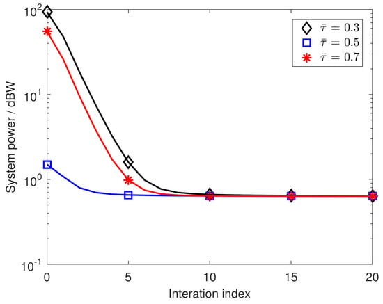
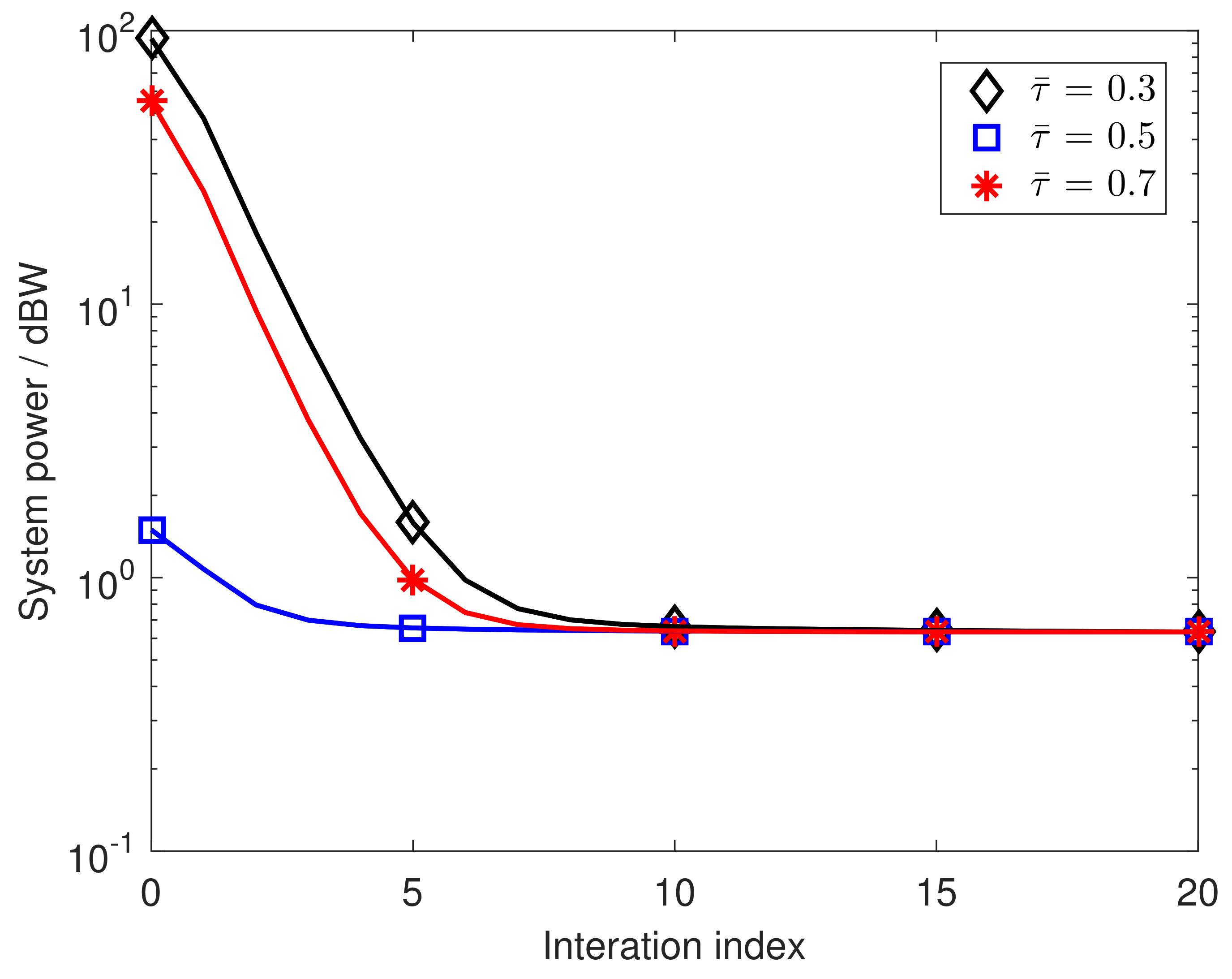
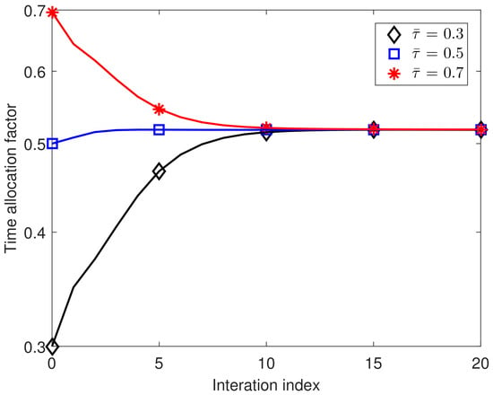
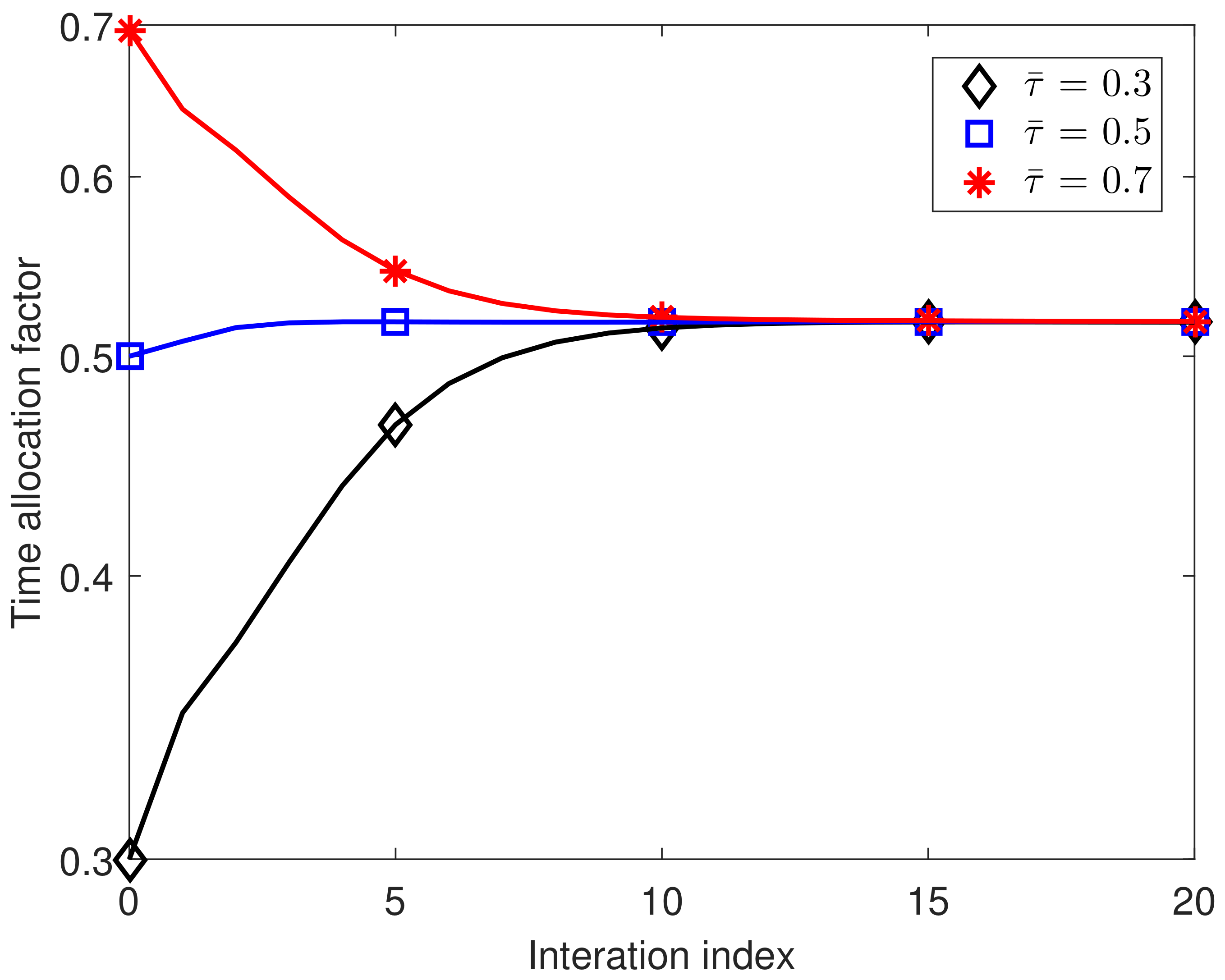
We first investigate the convergence performance of the iterative algorithm. Under the transmission rate requirements of bits/s/Hz and the conditions of three different initial time allocation factors, Figure 2 plots the variant curves of the system power versus the number of iterations. The simulation curves indicate that as the number of iterations increases, the system power obtained under the three initial time allocation factors gradually decreases and converges to the same constant value, demonstrating that the objective function of the iterative algorithm is convergent. Under the same QoS requirements and initial conditions, Figure 3 displays variant curves of the time allocation factor versus the number of iterations. The plots reveal that the variation in the time allocation factor with the number of iterations follows a trajectory similar to that of the system power, indicating that the optimization variable of the algorithm is also convergent.
Figure 2.
Convergence performance of the system power.
Figure 3.
Convergence performance of the time allocation factor.
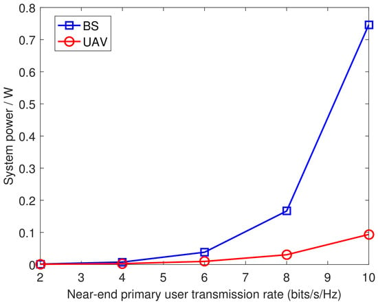
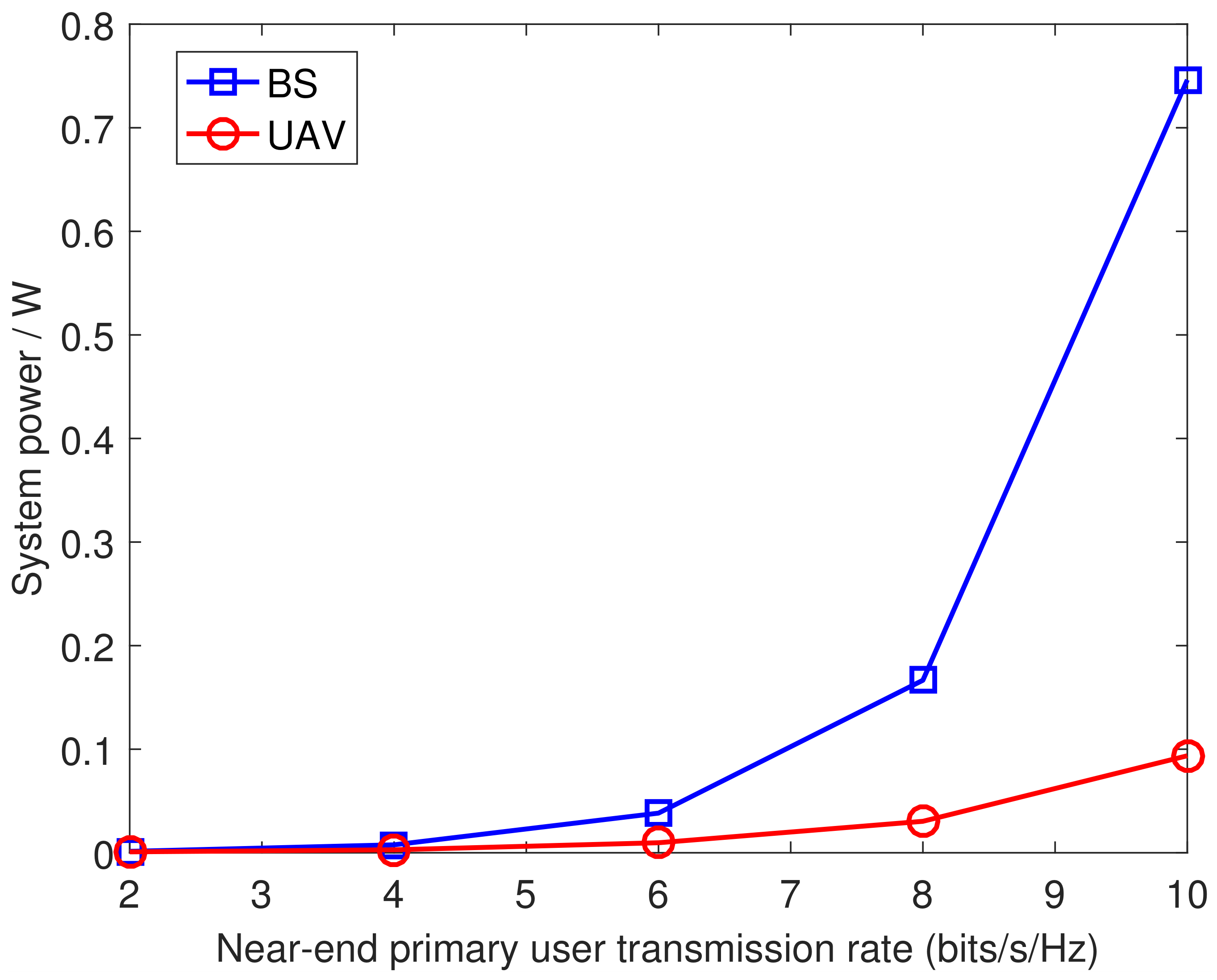
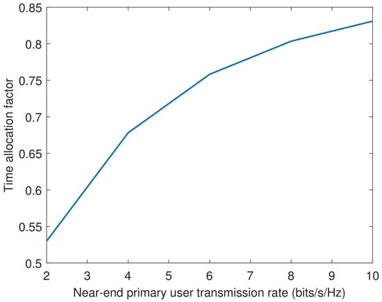
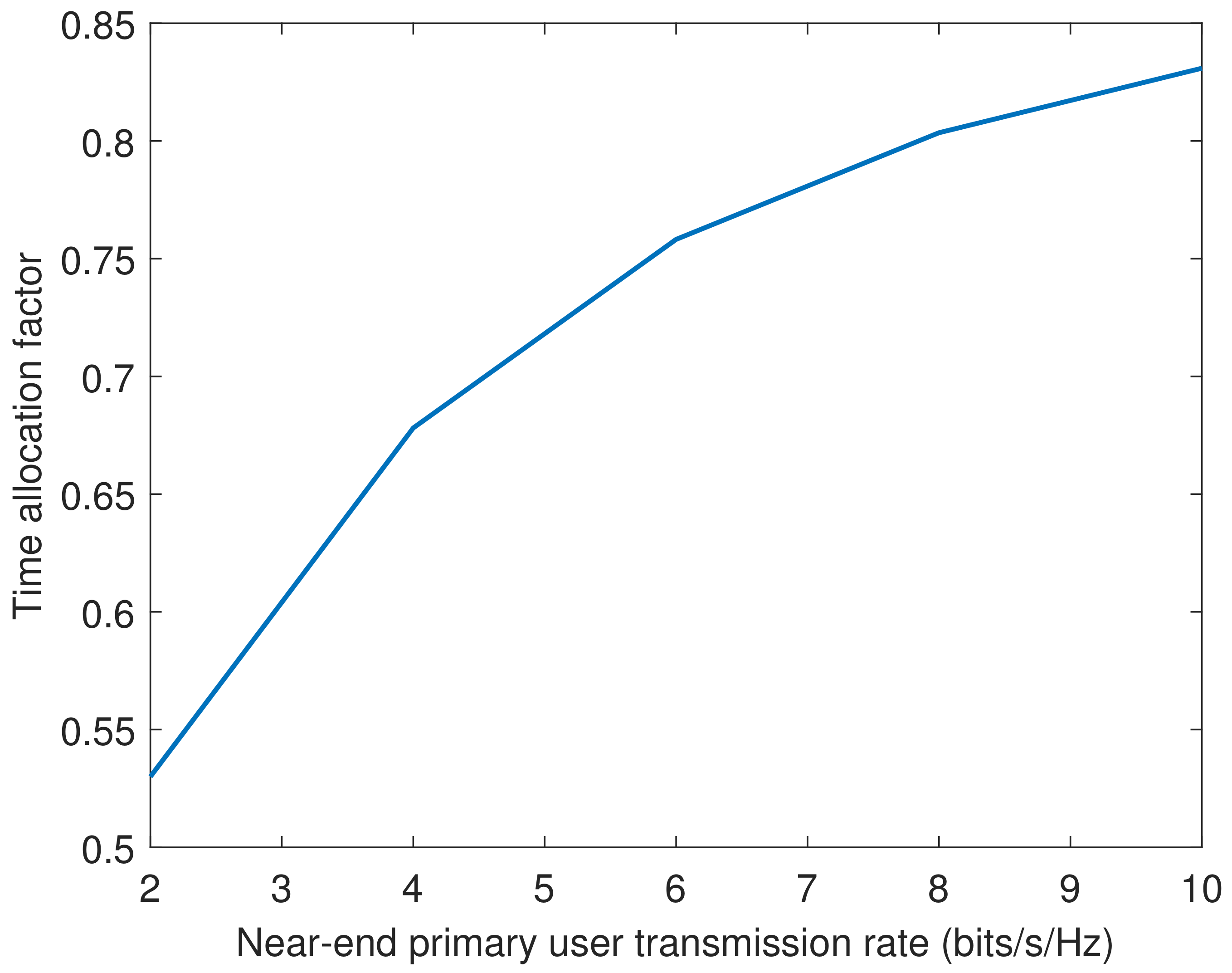
Next, we evaluate the system performance under various transmission QoSs. Under the condition that both the remote primary user transmission rate and the cognitive user transmission rate are set to the default value of 2 bits/s/Hz, Figure 4 and Figure 5 present the performance curves of the system power and the time allocation factors as functions of the near-end primary user transmission rate, respectively. To reveal the power consumption of the PT and UAV, the power consumed by the ground PT and the aerial UAV is shown separately in Figure 4, labeled as ‘BS’ and ‘UAV’ respectively. The simulation curves show that both the transmit power at the PT and the transmission time of the first phase increase quickly with the increase in the near-end primary user transmission rate. This result aligns well with the actual value, as higher QoS demands more transmission resources of power and time. On the other hand, the increase in the transmission time in the first phase implies a reduction in the transmission time in the second phase. With the transmission time being reduced, the UAV must boost its transmit power to maintain a constant transmission rate. Consequently, we observe that the power consumed by the UAV also gradually increases with the increase in the near-end primary user transmission rate.
Figure 4.
System power versus different transmission rates of the near-end primary user.
Figure 5.
Time allocation factor versus different transmission rates of the near-end primary user.
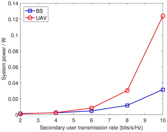
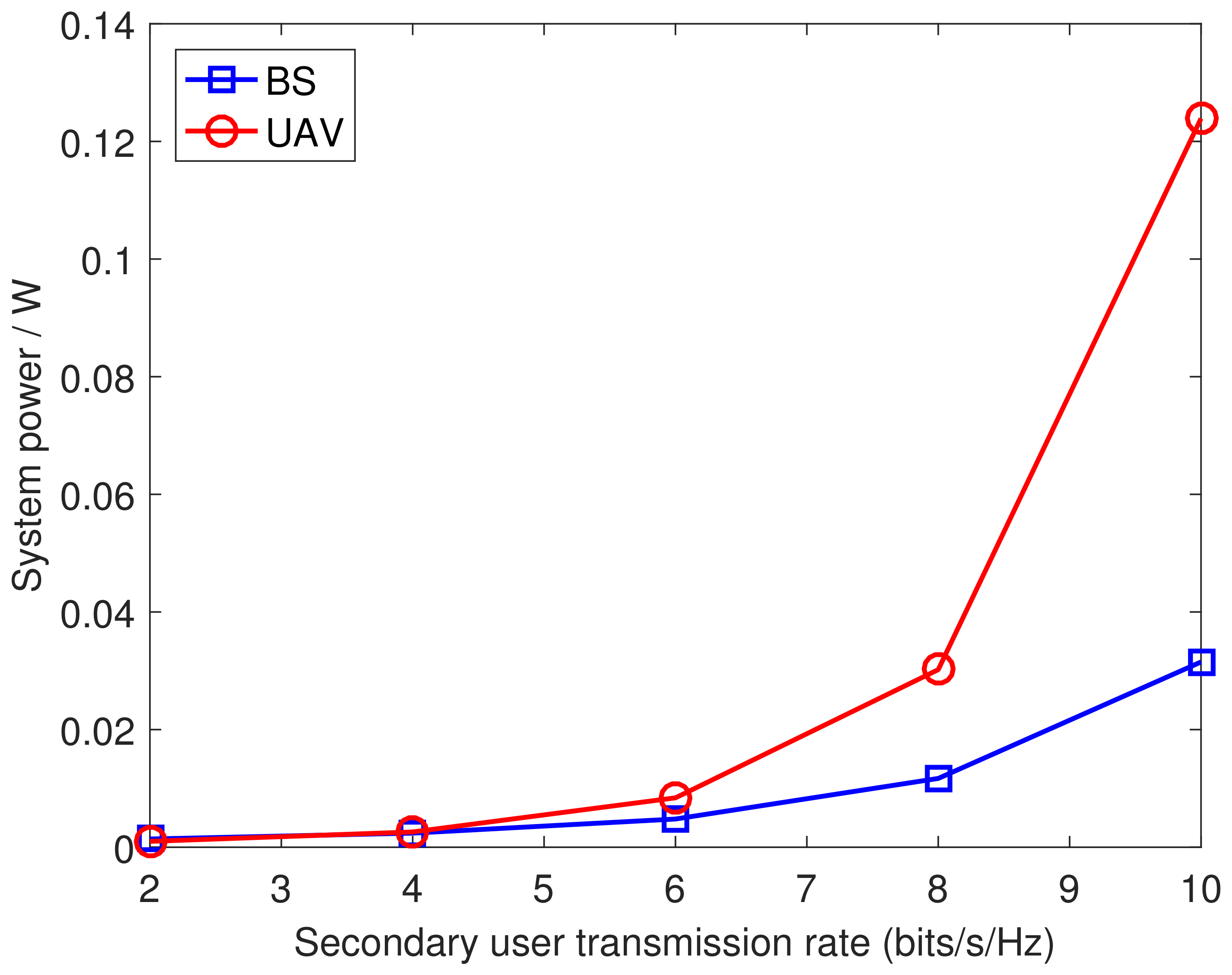
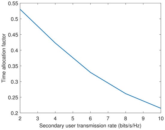
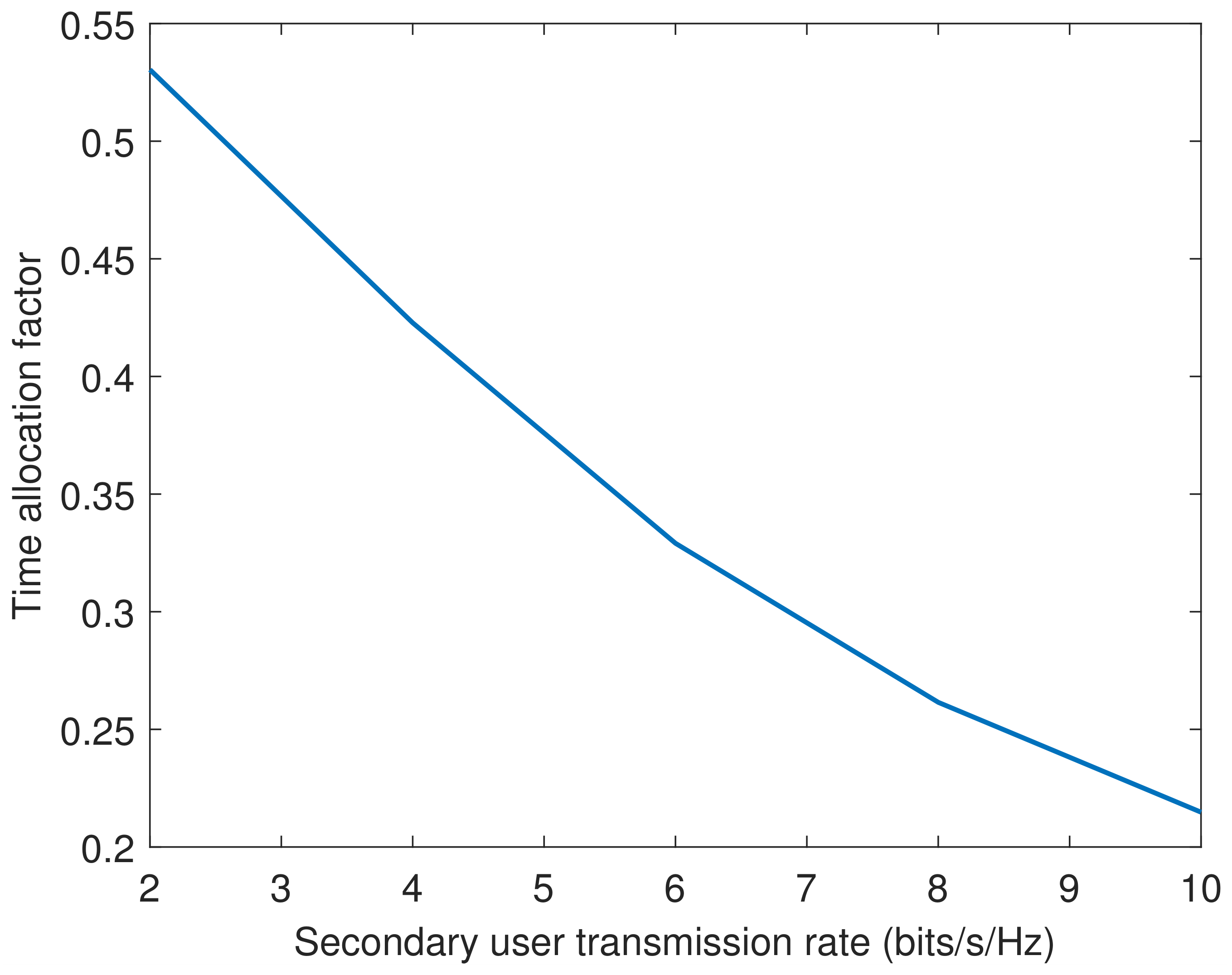
Under the condition of the default primary user transmission rate of 2 bits/s/Hz, Figure 6 and Figure 7 show the performance variation curves of the system power and the time allocation factor with the cognitive user transmission rate, respectively. The higher the cognitive user transmission rate, the more transmission resources of power and time are required. Therefore, we see that the transmit power and transmission time of the UAV increase significantly with the increase in the cognitive user transmission rate. On the other hand, an increase in the UAV transmission time means a decrease in the near-end PT transmission time. In order to maintain a constant near-end primary user transmission rate, it is necessary to increase the PT transmit power. Therefore, we see that the PT transmit power slowly increases with the increase in the cognitive user transmission rate.
Figure 6.
System power versus different transmission rates of the secondary user.
Figure 7.
Time allocation factor versus different transmission rates of the secondary user.
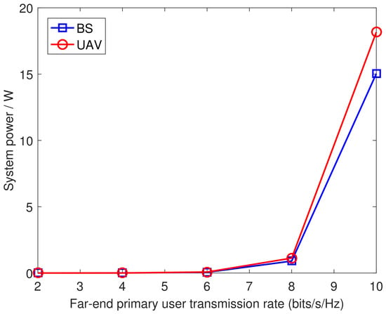
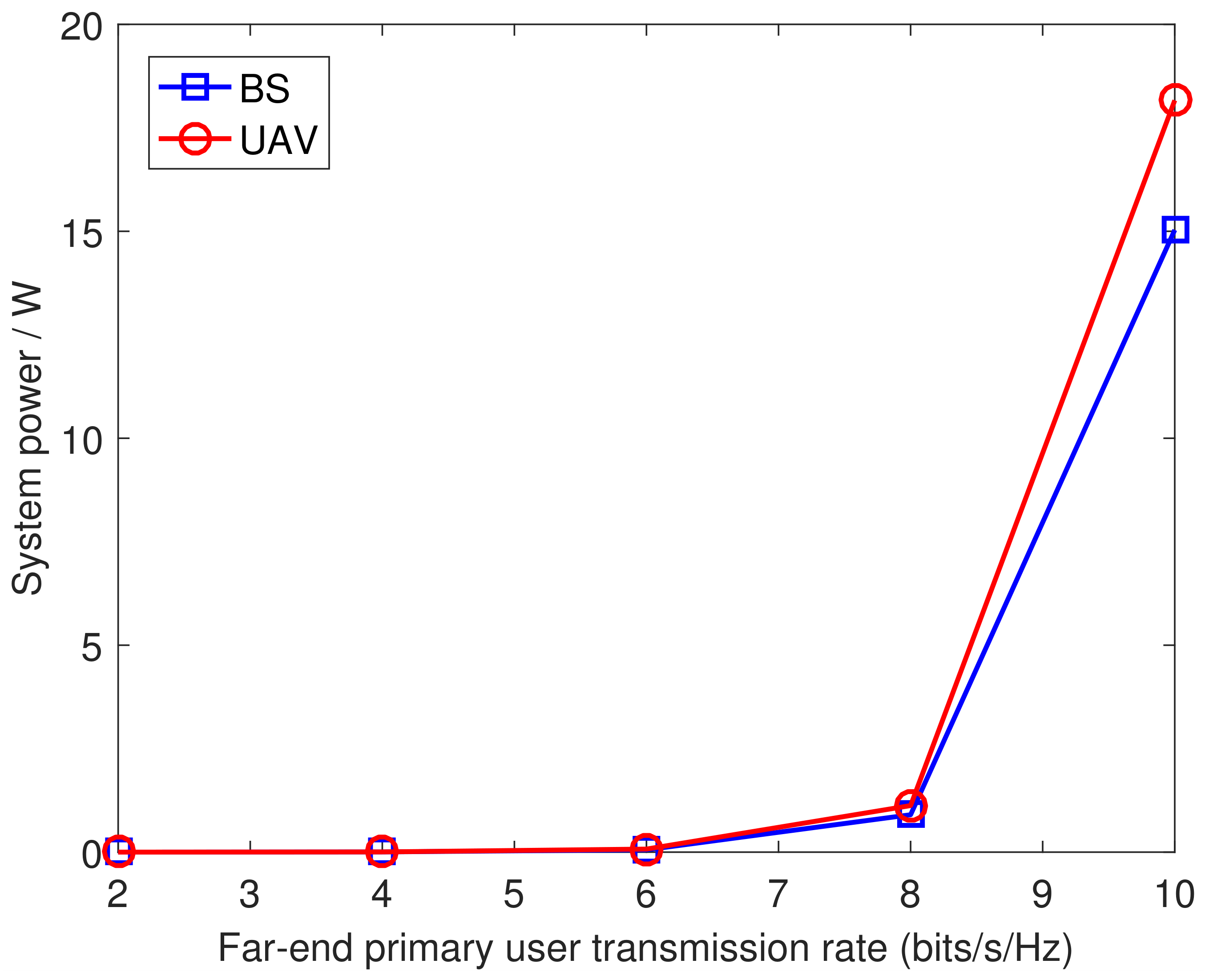
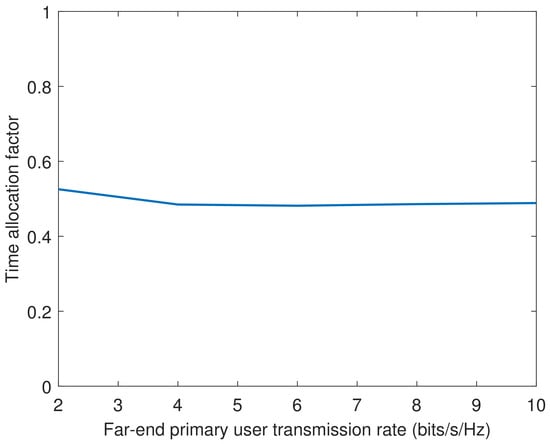
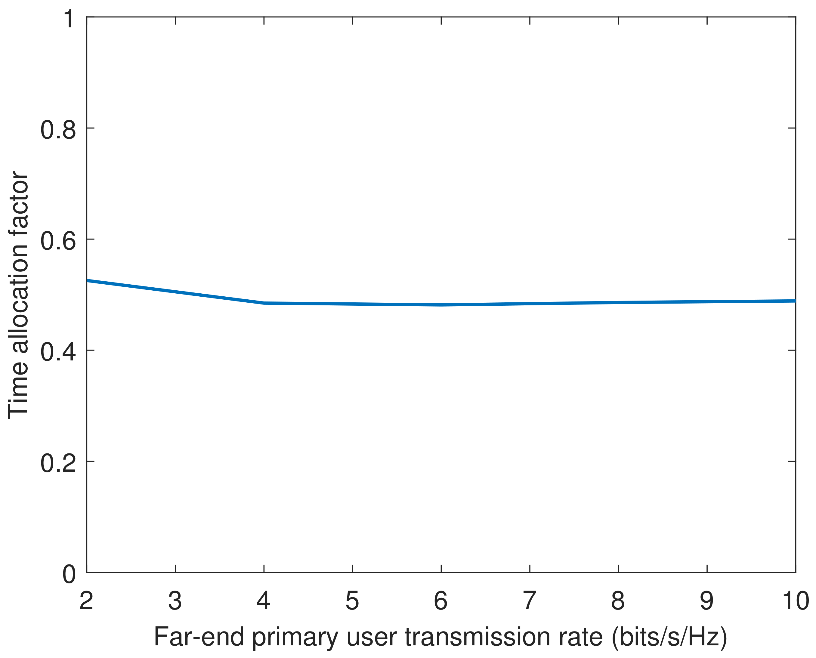
Under the condition that both the near-end primary user transmission rate and the cognitive user transmission rate are 2 bits/s/Hz, Figure 8 and Figure 9 show the performance variation curves of the system power and the time allocation factor with the remote primary user transmission rate, respectively. Due to the fact that the information transmission of the remote primary user goes through the first and second transmission phases successively, and both transmission phases need to afford the same transmission rate, the transmit power of the PT and UAV increases synchronously with the increase in the remote primary user transmission rate, and the transmission time is almost equally allocated between the two transmission phases.
Figure 8.
System power versus different transmission rates of the far-end primary user.
Figure 9.
Time allocation factor versus different transmission rates of the far-end primary user.
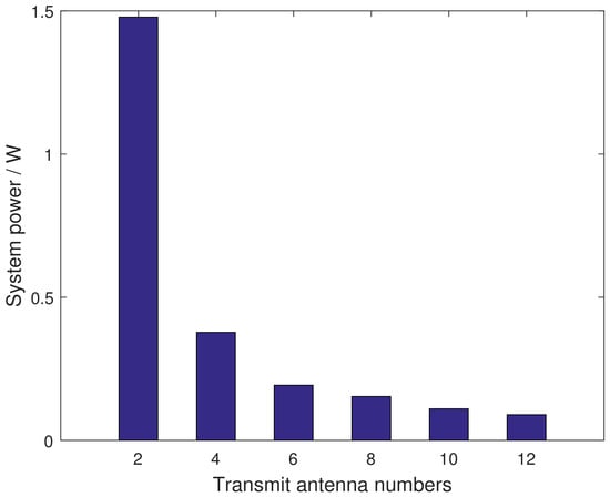
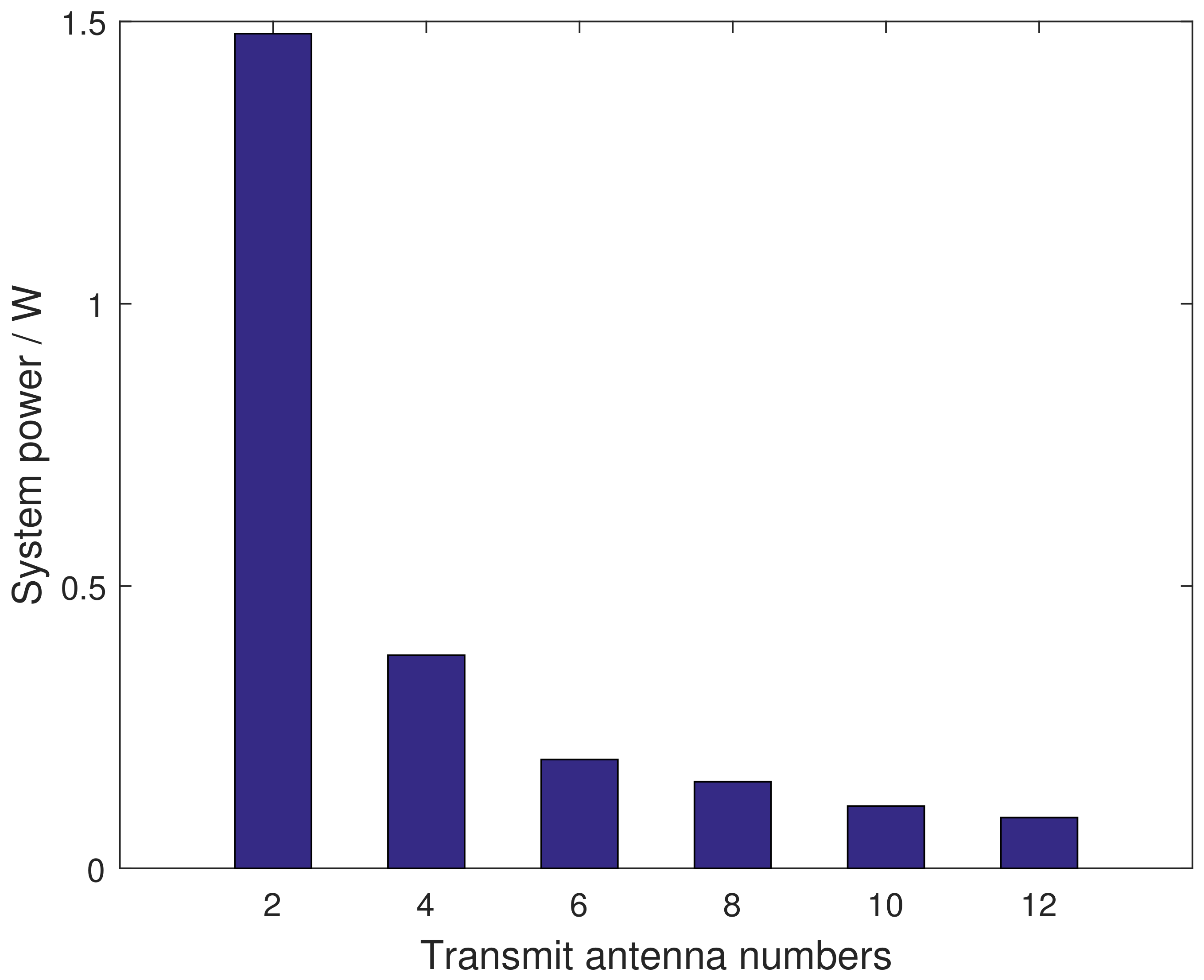
Under the transmission rate thresholds of bits/s/Hz, Figure 10 illustrates the histogram of the system power versus the number of transmit antennas where . The plots show that the system power decreases sharply with the increase in the number of transmit antennas. In Figure 10, we do not give the results for the single-antenna case in that the associated optimization problem is feasible, implying that the single-antenna system cannot afford the considered network setup and the given transmission requirement. These observations corroborate the effectiveness of the proposed scheme in the transmission capability enhancement.
Figure 10.
System power versus different numbers of transmit antennas.
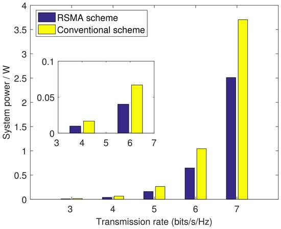
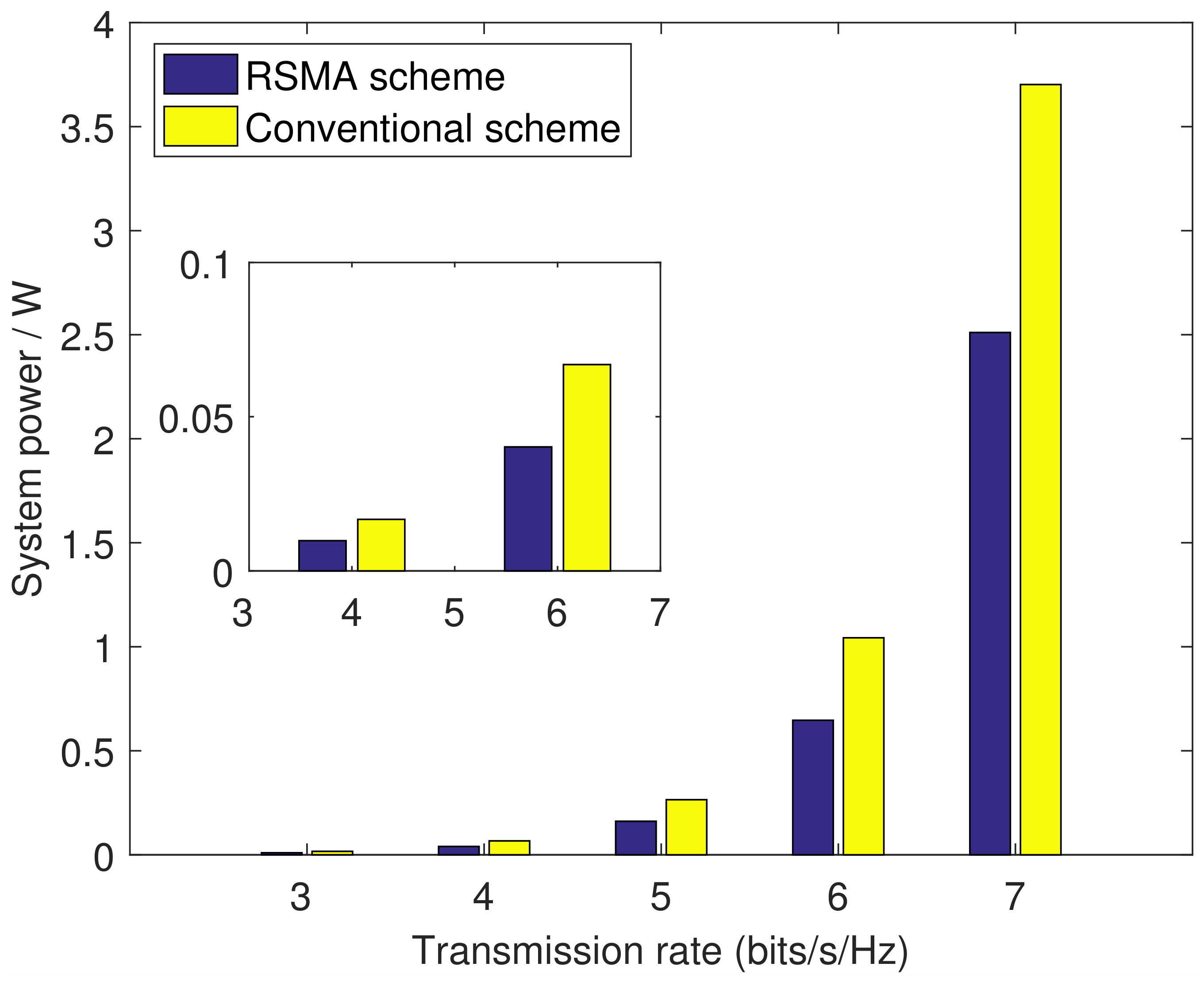
Finally, we compare the performance of our scheme with that of the traditional SDMA scheme. For the SDMA scheme, the transmit data is not split and an identical two-phase transmission protocol is used. In the first phase, the data intended for each PR is transmitted by the PT using an independent beamforming vector. Similarly, in the second phase, the data intended for the remote PR and for the SR are transmitted by the UAV using two independent beamforming vectors, respectively. For fair comparison, the time allocation variable between the two phases is also optimized in the SDMA scheme. In the case where the transmission rates of all users are the same and variable, Figure 11 shows the bar chart of the system power of these two schemes as a function of the user transmission rate. The results in the figure show that as the user transmission rate increases, the system power of both schemes increases exponentially. On the other hand, at the same user transmission rate, the system power required by the RSMA scheme is lower than that of the SDMA scheme, implying that RSMA can enhance the overall performance of the CCRANs.
Figure 11.
Performance comparison between the proposed air–ground CCRAN with RSMA and SDMA.
5. Conclusions
We have examined a multi-antenna RSMA and UAV-based air–ground CCRAN and considered the scenarios where the PT and the far-end PR cannot communicate directly and must rely on the UAV for cooperative information forwarding. A two-phase communication protocol with scalable transmission duration was established to coordinate information transmission between the two systems. A non-convex PM problem together with the iterative routine was formulated for the system design.
The following results can be obtained from the numerical simulations. (1) The established iterative routine for the non-convex optimization problem is guaranteed to converge. (2) The two-phase communication protocol with scalable transmission duration can well adapt to the possible different transmission requirements between the primary and secondary systems. (3) The multi-antenna RSMA-enabled CCRAN significantly enhanced the system transmission capability. (4) The multi-antenna RSMA-enabled CCRAN exhibits excellent performance advantages as compared with the multi-antenna RSMA-enabled one and the multi-antenna SDMA-enabled one.
Author Contributions
Conceptualization, D.-H.C.; methodology, D.-H.C.; software, Y.G.; validation, Y.G.; formal analysis, Y.G.; investigation, Y.G.; resources, Y.G.; data curation, Y.G.; writing—original draft preparation, Y.G.; writing—review and editing, D.-H.C.; visualization, Y.G.; supervision, D.-H.C.; project administration, D.-H.C.; funding acquisition, D.-H.C. All authors have read and agreed to the published version of the manuscript.
Funding
This research received no external funding.
Institutional Review Board Statement
Not applicable.
Informed Consent Statement
Not applicable.
Data Availability Statement
The data that support the findings of this study have been included in the manuscript. The codes that produce the associated data are available from the corresponding author on reasonable request.
Conflicts of Interest
The authors declare no conflicts of interest.
References
- Upadhya, A.; Saxena, V.N.; Dwivedi, V.K.; Singh, G. On the Evaluation of Fluid Antenna System-Assisted Cooperative Relaying with Diversity Combining. IEEE Open J. Commun. Soc. 2026, 7, 6703–6722. [Google Scholar] [CrossRef] [Scilit]
- Ammar, A.; Oun, A.; Martell, W.; Ajmal Khan, M. Deep Learning-Based Relay Selection in a Decode-and-Forward Cooperative System with Energy Harvesting and Signal Space Diversity. In Proceedings of the 2024 IEEE 67th International Midwest Symposium on Circuits and Systems (MWSCAS), Springfield, MA, USA, 11–14 August 2024. [Google Scholar]
- Denno, S.; Nishimura, H.; Hou, Y. Filter-and-Forward Cooperative Relaying in Double Selective Fading Channels. IEICE Trans. Commun. 2026, E109-B, 808–816. [Google Scholar] [CrossRef] [Scilit]
- Yahya, K.; Aldababsa, M.; Arashloo, B.A.; Al Dawsari, S.; Khan, S.A. Performance Analysis of Energy-Harvesting Amplify-and-Forward Relaying with Fluid Antenna Systems. Energies 2026, 19, 3502. [Google Scholar] [CrossRef] [Scilit]
- Song, S.; Hu, F.; Ling, Z.; Li, Z.; Jin, C. Max–Min Fairness of CR-RSMA-Based UAV Relay-Assisted Emergency Communication Network With Limited User Energy. IEEE Internet Things J. 2024, 11, 23998–24012. [Google Scholar] [CrossRef] [Scilit]
- Khan, M.; Mirza, J.; Ali, B.; Javed, M.A.; Dev, K.; Nkenyereye, L.; Bellavista, P. Joint Optimization of Semi-Passive IRS Phase Shifts and NOMA Power Coefficients for Cooperative CRNs. IEEE Trans. Green Commun. Netw. 2025, 9, 380–391. [Google Scholar] [CrossRef] [Scilit]
- Singh, C.K.; Upadhyay, P.K.; Lehtomäki, J.J. Performance Analysis and Deep Learning Assessment of Full-Duplex Overlay Cognitive Radio NOMA Networks Under Non-Ideal System Imperfections. IEEE Trans. Cogn. Commun. Netw. 2023, 9, 664–682. [Google Scholar] [CrossRef] [Scilit]
- Chen, D.-H.; Ruan, K. NOMA-Enabled Cooperative Two-Way Communications for Both Primary and Secondary Systems. Electronics 2026, 15, 389. [Google Scholar] [CrossRef] [Scilit]
- He, D.; Yuan, W.; Wu, J.; Liu, R. Ubiquitous UAV Communication Enabled Low-Altitude Economy: Applications, Techniques, and 3GPP’s Efforts. IEEE Netw. 2026, 40, 115–122. [Google Scholar] [CrossRef] [Scilit]
- Zhang, R.; Li, B.; Zhang, L.; Xie, J.; Wang, M. Learning with Dynamics: Autonomous Regulation of UAV Based Communication Networks with Dynamic UAV Crew. IEEE Commun. Mag. 2026, 64, 72–78. [Google Scholar] [CrossRef] [Scilit]
- Fan, R.; Huang, S. UAV Communications and Signal Processing for 6G: Opportunities, Challenges, and Emerging Directions. Drones 2026, 10, 577. [Google Scholar] [CrossRef] [Scilit]
- Hao, Y.; Li, M.; Xue, P.; Faissal El Bouanani, F.E.; Chen, W.; Han, Z. Outage Analysis of UAV-Assisted Cooperative Cognitive NOMA in IoT-Enabled Air–Ground Networks with Imperfect SIC and CSI. IEEE Internet Things J. 2025, 12, 26984–27002. [Google Scholar] [CrossRef] [Scilit]
- Wang, Q.; Xing, C.; Zhao, N.; Niyato, D. UAV-Assisted Covert Transmission for Cooperative Cognitive Radio Networks. IEEE Trans. Wirel. Commun. 2026, 25, 1594–1608. [Google Scholar] [CrossRef] [Scilit]
- Min, L.; Li, J.; He, Y.; Wang, W. Secure Rate-Splitting Multiple Access for Maritime Cognitive Radio Network: Power Allocation and UAV’s Location Optimization. J. Mar. Sci. Eng. 2023, 11, 1012. [Google Scholar] [CrossRef] [Scilit]
- Swetlana; Das, S. Enhancing Aerial Network Performance with RSMA and Stackelberg Game Theory. In Proceedings of the IEEE 6th India Council International Subsections Conference, Rourkela, India, 21–23 August 2025. [Google Scholar]
- Wang, D.; He, J.; He, Y.; Men, S.; Xu, Q.; Yang, X.; Liang, W. Cooperative Rate Splitting Multiple Access in Cognitive Radio Networks: Power Allocation and Location Optimization. In Proceedings of the International Conference on Communications Workshops, Rome, Italy, 28 May–1 June 2023. [Google Scholar]
- Liang, L.; Tian, Z.; Huang, H.; Zhang, N.; Zhang, D.; Li, Y. Performance Analysis of Overlay Cognitive Cooperative Communication Based on RSMA. In Proceedings of the International Conference on Ubiquitous Communication, Xi’an, China, 5–7 July 2024. [Google Scholar]
- Chen, D.-H. Integrated Cooperative Sensing and Bidirectional MIMO Communications Enabled by Devices Cooperation and NOMA. IEEE Internet Things J. 2026, 13, 17080–17095. [Google Scholar] [CrossRef] [Scilit]
- Ren, Q.; Li, Y.; Zhang, Z.; Lu, S. OTFS-SDMA for Massive Grant-Free Random Access in LEO Satellite Internet of Things. IEEE Trans. Wirel. Commun. 2025, 24, 6902–6916. [Google Scholar] [CrossRef] [Scilit]
- Gamal, S.; Rihan, M.; Hussin, S.; Zaghloul, A.; Salem, A.A. Multiple Access in Cognitive Radio Networks: From Orthogonal and Non-Orthogonal to Rate-Splitting. IEEE Access 2021, 9, 95569–95584. [Google Scholar] [CrossRef] [Scilit]
- Huang, L.; Qu, D.; Zhou, J.; Zhang, J. The Optimization of UAV-Assisted Downlink Transmission Based on RSMA. Mathematics 2025, 13, 13. [Google Scholar] [CrossRef] [Scilit]
- Lyu, X.; Aditya, S.; Clerckx, B. Rate-Splitting Multiple Access for Integrated Sensing and Communications: A First Experimental Study. IEEE Trans. Wirel. Commun. 2026, 25, 10498–10513. [Google Scholar] [CrossRef] [Scilit]
- Soleymani, M.; Clerckx, B.; Schober, R.; Hanzo, L. RIS-Aided RSMA Improves the Latency vs. Energy Trade-Off in the Finite Block Length MIMO Downlink. IEEE Open J. Veh. Techn. 2026, 7, 1036–1048. [Google Scholar] [CrossRef] [Scilit]
- Pang, H.; Ji, F.; Wen, M.; Xu, L.; Zhao, J.; Ning, Z.; Panayirci, E. Safeguarding RSMA Networks with Cooperative Jamming and Relaying. IEEE Trans. Veh. Technol. 2026, 75, 10468–10482. [Google Scholar] [CrossRef] [Scilit]
- Khisa, S.; Elhattab, M.; Assi, C.; Ghrayeb, A.; Qaraqe, M.; Kaddoum, G. Coordinated Full-Duplex Cooperative Transmission with RSMA in Multi-Cell Networks. IEEE Commun. Lett. 2025, 29, 2959–2963. [Google Scholar] [CrossRef] [Scilit]
- Maghrebi, Y.; Elhattab, M.; Assi, C.; Ghrayeb, A.; Kaddoum, G. Cooperative Rate Splitting Multiple Access for Active STAR-RIS Assisted Downlink Communications. IEEE Wirel. Commun. Lett. 2024, 13, 2827–2831. [Google Scholar] [CrossRef] [Scilit]
- Lu, J.; Li, X.; Zhang, H.; Leung, V.C.M. Semantic Information Assignment and Relay Selection for Green Cooperative RSMA Networks. IEEE Internet Things J. 2026, 13, 13183–13197. [Google Scholar] [CrossRef] [Scilit]
- Zhang, M.; Cheng, H.; Su, R.; Lu, Y.; Wang, S.; Zhang, L. A Cognitive Transmission and Deployment Strategy for UAV-Assisted Hybrid RIS Relay Network. EURASIP J. Adv. Signal Process. 2025, 33, 2025. [Google Scholar] [CrossRef] [Scilit]
- Ma, S.; Shen, B.; Zhang, C.; Li, H.; Li, N.; Chai, J.; Huang, C.; Li, S.; Shi, G. Optimal and Robust Beamforming Design for Multiuser Semantic Interference Networks. IEEE Internet Things J. 2025, 12, 54845–54858. [Google Scholar] [CrossRef] [Scilit]
Disclaimer/Publisher’s Note: The statements, opinions and data contained in all publications are solely those of the individual author(s) and contributor(s) and not of MDPI and/or the editor(s). MDPI and/or the editor(s) disclaim responsibility for any injury to people or property resulting from any ideas, methods, instructions or products referred to in the content. |
© 2026 by the authors. Licensee MDPI, Basel, Switzerland. This article is an open access article distributed under the terms and conditions of the Creative Commons Attribution (CC BY) license.