


Abstract
This paper investigates millimeter-wave cluster characteristics for intra-vehicle access links in a passenger vehicle cabin. Double-directional measurements at 61.5 GHz were conducted for two selected receiver locations near the door switches. High-resolution multipath components were extracted from the measured channel transfer functions and subsequently grouped into clusters. Based on the identified clusters, the intra-cluster delay and angular characteristics were characterized and parameterized for the measured scenarios. The results indicate that the dominant clusters are primarily formed by single reflections with relatively small excess delays, while higher-order reflections contribute only weak power. The resulting scenario-specific cluster parameters provide a physically interpretable basis for evaluating future high-data-rate intra-vehicle wireless links.
1. Introduction
5G evolution and 6G systems are envisioned as communication infrastructures supporting diverse service requirements, broader vertical integration, and high-capacity, low-latency wireless connectivity [1,2]. In particular, intelligent transportation and connected mobility are expected to rely on advanced wireless links, and automotive white papers have highlighted both off-board and on-board communications as important enablers of future vehicle services [1,3]. At the same time, the number of onboard sensors, cameras, displays, and electronic control units continues to increase, making conventional cable-based vehicle architectures heavier and less flexible. Accordingly, intra-vehicle wireless links are attracting attention for reducing wiring complexity, lowering vehicle weight, and relaxing device-placement constraints.
While existing in-vehicle wireless connectivity can be supported by technologies such as Bluetooth, WiFi, and sub-6-GHz cellular systems, future cable-replacement applications, including high-resolution displays, cameras, and sensor networks, may require multi-Gbit/s data rates. Millimeter-wave bands are attractive for such applications because of their large available bandwidth and the short communication distances within vehicle cabins. However, the passenger cabin is a compact and geometrically complex environment in which seats, windows, pillars, and other interior components cause blockage, reflection, and scattering. Accurate channel characterization is therefore essential for assessing the feasibility of high-frequency intra-vehicle systems and for developing practical channel models.
Recent studies have characterized intra-vehicle channels over multiple frequency bands and scenarios. Path loss, delay spread, and transmission loss through vehicle components vary significantly across FR1/FR2/FR3 and sub-THz bands, particularly under obstructed conditions near seats and under-seat structures [4]. Channel comparisons below 7 GHz, in the mm-wave band, and in the sub-THz band have further shown that major multipath components can be observed across bands, whereas higher-frequency channels become increasingly sparse, highlighting the importance of spatial channel profiling for high-frequency intra-vehicle systems [5]. In addition, intra-vehicle measurements in the 290–310 GHz band have reported delay- and angle-domain channel characteristics, including the power angular delay profile (PADP) and angular power spectrum (APS), together with geometry-based interpretation of major multipath components (MPCs) [6].
A preliminary experimental study on mm-wave multipath propagation in passenger vehicles was reported in [7]. Although that work clarified the basic propagation characteristics in the vehicle cabin based on the measured APS, the measurements in [7] were conducted for selected antenna directions corresponding to expected dominant propagation paths. In contrast, the present study employs angle-domain scanning measurements, enabling double-directional (d-d) MPC extraction, clustering, and intra-cluster characterization that jointly consider the delay and angular domains. Existing studies have mainly focused on path loss, delay spread, penetration loss, spatial consistency, or dominant-path identification [4,5,6,8,9], whereas beamforming-oriented link design and performance evaluation can benefit from a description of both inter- and intra-cluster characteristics. In this paper, d-d mm-wave channel measurements are conducted inside a passenger vehicle, and the intra-cluster characteristics are investigated for two selected receiver locations by jointly considering the delay and angular domains. Multipath parameter extraction and clustering are applied to identify the dominant propagation mechanisms and to derive scenario-specific intra-cluster parameters, thereby providing a measurement-based characterization of the cluster behavior in the two investigated intra-vehicle links.
2. Measurement Campaign
2.1. Measurement Setup
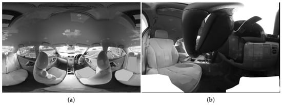
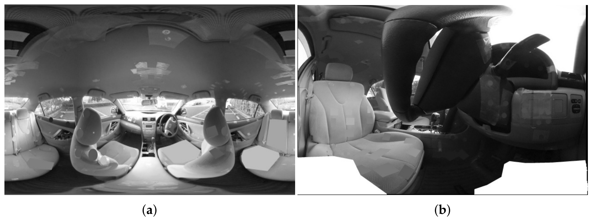
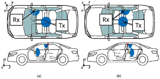
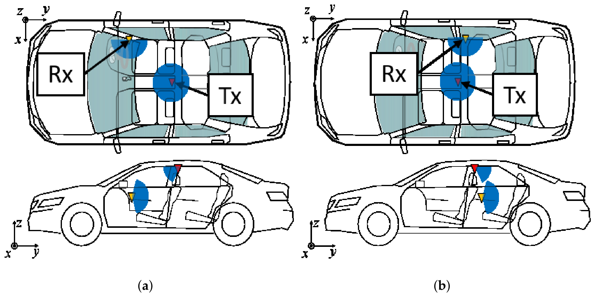
Measurements were conducted inside a standard passenger vehicle. Photographs of the vehicle interior are shown in Figure 1a,b, while the transmitter (Tx) and receiver (Rx) positions are illustrated in Figure 2a,b. The ceiling-mounted Tx was selected to emulate a centralized intra-vehicle access point, while the Rx positions emulate in-vehicle devices located near door-control interfaces. The Rxs were positioned adjacent to the front-door switch in Scenario 1 and the rear-door switch in Scenario 2. The corresponding Tx–Rx distances were approximately 126 cm and 84 cm.
Figure 1.
Photographs of the vehicle interior. (a) View from the Tx position (on the roof). (b) View from the Rx position (adjacent to the door switch).
Figure 2.
Tx and Rx antenna positions. The blue sector indicates the antenna scanning coverage, and the light-blue region indicates the glass window. (a) Scenario 1; (b) Scenario 2.
Measurements were performed using a vector network analyzer (VNA) (N5247B, Keysight, Tokyo, Japan). Table 1 summarizes the measurement parameters. Before the measurements, the VNA was calibrated at the antenna cable ends, and the calibrated was used as the measured channel transfer function. The measurement bandwidth was 9 GHz, resulting in a delay resolution of approximately ns. The total number of frequency points was 301. On the transmitter side, a horn antenna with a half-power beamwidth (HPBW) and a gain of 15 dBi was used, while on the receiver side, a horn antenna with a HPBW and a gain of 22 dBi was employed. For the angle-domain measurements, both the Tx and Rx antennas were mounted on rotation platforms, and the angles listed in Table 1 were scanned. Due to the long acquisition time required for the full angular scan, each scenario was measured once under static cabin conditions.
Table 1.
Measurement parameters.
2.2. Power Spectra
The channel transfer function (CTF) measured by the VNA is converted into the channel impulse response (CIR) by applying the inverse Fourier transform. The resulting angle-resolved CIR is a multidimensional function characterized by the Tx angle, Rx angle, and delay. To facilitate its interpretation, dimensionality reduction is applied to represent the data as power spectra. In this study, the power delay profile (PDP) and APS are used for this purpose. The squared magnitude of the d-d CIR is defined as the d-d angular-delay power spectrum (DDADPS):
where denotes the propagation delay, and denote the elevation angles at the Rx and Tx, respectively, and and denote the corresponding azimuth angles.
By integrating the DDADPS over the dimensions that are not of interest, the PDP and APS are obtained as
where and denote the compensation factors for the power increase caused by the overlap of Tx and Rx antenna beams, respectively [10]. Equation (2) defines the PDP, while (3) and (4) define the APS at the Tx and Rx, respectively. These representations facilitate visualization and interpretation of the measurement results.
Furthermore, the measured DDADPS contains additive noise, which is accumulated when the power is synthesized over the angular dimensions. To suppress this effect, a noise threshold was applied to the DDADPS before calculating the PDP and APS. Assuming that the complex noise samples follow a zero-mean complex Gaussian distribution, the noise power follows an exponential distribution. Accordingly, the noise threshold is given by
where denotes the mean noise power and is the probability that the noise power is below the threshold. In this study, was used. The noise statistics were estimated from a delay region in which no significant propagation components were observed. Components below were removed before the power synthesis.
3. Scattering Processes
3.1. MPC Extraction and Clustering
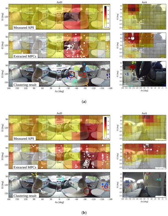
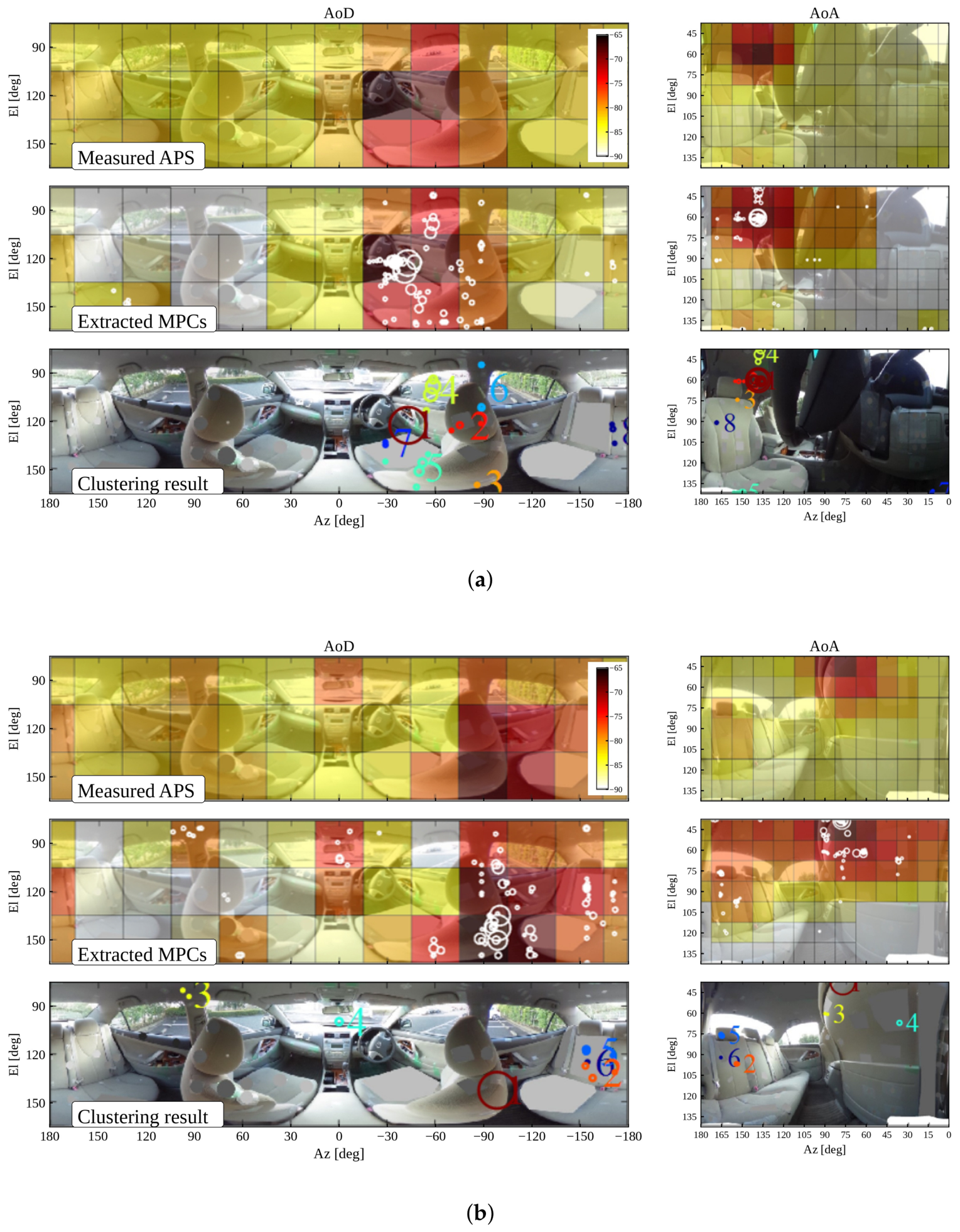
The Sub-grid CLEAN algorithm [11] was employed to extract the MPCs with super-resolution. The algorithm enables MPC parameter estimation beyond the physical angular sampling intervals through sub-grid parameter optimization. In this work, MPC extraction was performed using a angular search step in the sub-grid optimization, which does not represent the physical angular resolution of the antenna system. The extraction was terminated when the number of extracted MPCs reached the predefined number of paths. As a result, 65 and 50 paths were extracted for Scenario 1 and Scenario 2, respectively. The d-d channel analysis results for both scenarios are shown in Figure 3. The upper and middle panels of Figure 3 compare the measured APSs and the APSs reconstructed from the extracted MPCs. The close agreement between the measured and reconstructed APSs indicates that the extracted MPC set sufficiently reproduces the measured angular channel characteristics. In the mm-wave band, diffuse scattering around specular reflections generates multiple MPCs that form clusters with spatiotemporal spread. The strongest component in each cluster is referred to as the cursor, whereas the remaining pre-cursor and post-cursor components are regarded as intra-cluster components [12,13,14,15]. To classify the extracted MPCs into clusters with similar propagation characteristics, the K-PowerMeans algorithm [16] was applied. The cluster identification results for both scenarios are shown in the lower panels of Figure 3, and the corresponding cluster parameters are summarized in Table 2.
Figure 3.
D-d channel analysis results: measured APS (top), extracted MPCs on reconstructed APS (middle), and clustered MPCs (bottom). The numbers in the bottom panels denote cluster indices. (a) Scenario 1; (b) Scenario 2.
Table 2.
Characteristics of identified clusters. Excess loss (EL) is defined relative to the free-space path gain (FSPG). The symbol “#” denotes the cluster index.
3.2. Propagation Path Identification
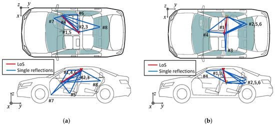
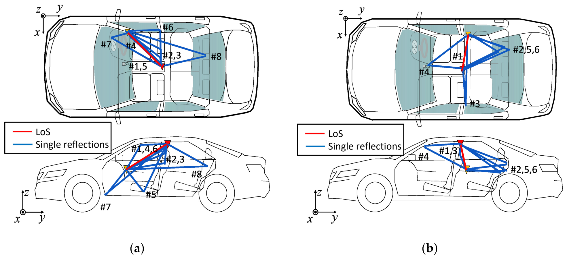
To investigate the physical propagation mechanisms, the extracted clusters were identified based on their delay and angular characteristics. The identification results are shown in Figure 4a,b. The propagation paths were identified based on the delay and angle information of each cluster, together with a consistency check against the vehicle geometry and previously reported measurement results in [7]. From these results, the corresponding propagation mechanisms were inferred. In both scenarios, the first Fresnel zone, with a diameter of approximately 6–8 cm, was partially obstructed by interior components such as the steering wheel and seat cushions. As a result, attenuations of dB and dB were observed for Scenario 1 (#1) and Scenario 2 (#1), respectively. In addition, multiple clusters corresponding to reflections from the seat surfaces were observed in Scenario 1 (#2, #3, #5, and #8) and Scenario 2 (#2, #5, and #6). These reflections are presumed to originate from metallic structures within the seats or from the metal partition separating the rear seats from the trunk.
Figure 4.
Propagation path identification results. (a) Scenario 1; (b) Scenario 2.
In practice, however, the seats are likely to be occupied by passengers, and the driver’s seat is always occupied during vehicle operation. Therefore, human-body effects should be considered for a more realistic characterization of the propagation paths. The parameters obtained in this study should be regarded as baseline characteristics of an unoccupied passenger cabin. Since the proposed model is MPC-based, human-body effects can in principle be incorporated in transmission simulations by introducing additional blockage, absorption, and scattering effects on the relevant propagation paths. Such effects may modify the K-factor and intra-cluster angular spreads. Dedicated measurements under occupied conditions are nevertheless required to calibrate and validate these extensions.
4. Cluster Channel Model
Following the parameter-based channel-modeling framework adopted in IEEE 802.11ad/ay [12,13] and related studies [14,15], the propagation channel is characterized by a set of parameters describing the cluster structure and the associated intra-cluster statistics of a given scenario. In this work, a scenario-specific stored channel representation is constructed from the measured cluster structure, while the intra-cluster delay and angular characteristics are parameterized using the stochastic framework adopted in IEEE 802.11ad/ay. Throughout Section 2 and Section 3, the extracted propagation components are referred to as MPCs. In this section, for stochastic channel generation, the intra-cluster constituents are represented as rays following the conventional cluster-based modeling framework.
4.1. Stochastic Channel Parameter Extraction
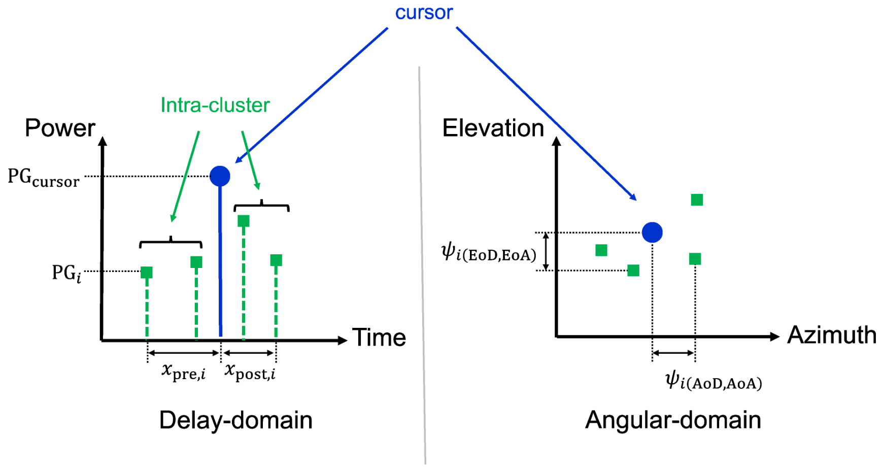
As discussed earlier, each cluster contains intra-cluster components that exhibit spatiotemporal dispersion. The extent of this dispersion is referred to as the intra-cluster characteristics. Figure 5 illustrates the concept of intra-cluster parameter extraction in the delay and angular domains. The strongest component within a cluster is defined as the cursor, while the remaining components are regarded as intra-cluster rays. Delay-domain parameters are extracted from the temporal distribution of rays around the cursor, whereas angular-domain parameters are characterized by the RMS angular spread around the cluster centroid. In this work, the intra-cluster statistics were extracted only from NLoS clusters. The LoS component was treated separately because it represents a direct propagation path without the spatiotemporal dispersion associated with scattering-generated clusters. In the delay domain, the pre-cursor and post-cursor components are modeled separately. In particular, three parameters are defined for both the pre-cursor and post-cursor components: the power ratio , the power decay constant , and the arrival rate of rays . Here, and are defined as follows:
Here, denotes the path gain, denotes the number of pre-cursor or post-cursor rays, and is the total received power of the cursor, obtained by summing the powers of its constituent rays, while represents the received power of the ith ray. The term denotes the time difference between adjacent rays in the delay domain, and is defined as the reciprocal of the mean inter-arrival time.
Figure 5.
Illustration of intra-cluster parameter extraction.
Let the cursor arrival time be the reference delay, i.e., . Then, pre-cursor components are defined for , whereas post-cursor components are defined for . Under this definition, the mean amplitudes are modeled as exponentially decaying functions away from the cursor:
The parameters are estimated from least-squares fits to the available pre-cursor and post-cursor components, respectively. However, owing to the very small intra-cluster delay spread in the vehicle cabin, the measured components are concentrated at only a few distinct delay offsets. Therefore, the available samples are insufficient for a meaningful formal goodness-of-fit assessment of the exponential decay assumption. The resulting values should thus be regarded as scenario-specific descriptive reference parameters following the IEEE 802.11ad/ay framework, rather than statistically validated decay constants.
In the angular domain, the intra-cluster distribution is modeled by a Gaussian distribution characterized by the RMS angle spread. Let represent the angular parameters for any of the domains: azimuth-of-departure (AoD), elevation-of-departure (EoD), azimuth-of-arrival (AoA), or elevation-of-arrival (EoA). The RMS angle spread and the mean angle are then given by:
where N is the number of rays in the cluster, and and denote the angle and the path gain of the i-th ray, respectively. Based on these procedures, the intra-cluster stochastic parameters were derived from all non-line-of-sight (NLoS) clusters in Scenario 1 and Scenario 2. The resulting parameter values are summarized in Table 3.
Table 3.
Intra-cluster parameters.
4.2. Discussion
By examining the cursor delays for both scenarios, the delay difference between the line-of-sight (LoS) component and the latest arriving cluster is ns in Scenario 1 and ns in Scenario 2, corresponding to excess path lengths of approximately m and m, respectively. This suggests that clusters produced by multiple reflections incur large excess path lengths relative to the LoS path and contribute only weak power; therefore, they are unlikely to constitute dominant propagation paths. Accordingly, the dominant propagation mechanisms are mainly associated with clusters generated by single reflections with relatively small excess delays from the LoS path. This observation is also supported by the EL statistics summarized in Table 2. The average EL of single-reflection clusters was 26.4 dB and 24.3 dB in Scenarios 1 and 2, respectively, whereas the corresponding values for multi-reflection clusters were 34.2 dB and 31.2 dB. Thus, multi-reflection clusters exhibited approximately 7–8 dB larger EL than single-reflection clusters.
Furthermore, the intra-cluster delay and angular spreads were found to be smaller than those typically reported for indoor wall-scattering clusters [14]. This may be attributed to the relatively smooth surfaces of scatterers within the vehicle cabin. In the measured scenarios, the 9-GHz bandwidth provided sufficient resolution to characterize these small spreading characteristics. Accordingly, the parameters in Table 3 represent baseline values for the measured unoccupied cabin and should not be directly applied to occupied conditions without accounting for human-body effects. The reported cluster parameters are specific to the investigated receiver locations, and their spatial consistency should be evaluated through measurements at additional locations. Furthermore, the reported parameters were obtained for a specific passenger vehicle at 61.5 GHz. Their applicability to other vehicles and frequency bands should be investigated through additional measurements.
Recent studies have highlighted the importance of channel-model-driven optimization for future 6G aerial-terrestrial integrated networks [17]. The scenario-specific cluster parameters obtained in this study may serve as local channel descriptions within such broader optimization frameworks, although their extension to dynamic environments requires further investigation.
5. Conclusions
This paper investigated mm-wave propagation inside a passenger vehicle using d-d channel measurements and cluster analysis. High-resolution multipath extraction facilitated detailed characterization of the channel parameters and clustering based on multidimensional similarity, clarifying the underlying propagation mechanisms in the vehicle cabin. The results showed that the dominant propagation mechanisms are mainly associated with the LoS path and single reflections with relatively small excess delays, whereas higher-order reflections contribute only weak power. These findings indicate that mm-wave intra-vehicle system design should prioritize robust utilization of the LoS and major single-reflection paths. Moreover, the small intra-cluster delay and angular spreads support beamforming-oriented link design and channel emulation based on a compact cluster representation. The reported parameters represent baseline characteristics of an unoccupied cabin, and human-body effects under occupied conditions remain to be evaluated. The proposed model therefore provides a practical basis for performance evaluation and channel modeling of future high-data-rate intra-vehicle wireless links.
Author Contributions
Conceptualization, M.K.; Methodology, S.Y. and K.M. (Kensuke Matsui); Validation, K.M. (Kenji Matsushita); Formal analysis, S.Y.; Investigation, S.Y.; Resources, K.M. (Kensuke Matsui); Data curation, K.M. (Kensuke Matsui); Writing—original draft, S.Y.; Writing—review and editing, M.K. and K.M. (Kenji Matsushita); Visualization, S.Y.; Supervision, M.K.; Project administration, K.M. (Kenji Matsushita); Funding acquisition, M.K. All authors have read and agreed to the published version of the manuscript.
Funding
This research was funded by Yazaki Corporation under a collaborative research agreement with Niigata University.
Data Availability Statement
The original contributions presented in this study are included in the article. Further inquiries can be directed to the corresponding author.
Conflicts of Interest
Author Authors Satoshi Yamakawa, Kenji Matsushita, and Kensuke Matsui are employed by the company Yazaki Corporation. The remaining author declares that the research was conducted in the absence of any commercial or financial relationships that could be construed as a potential conflict of interest.
References
- ITU-R. IMT Vision–Framework and Overall Objectives of the Future Development of IMT for 2020 and Beyond. Recommendation ITU-R M.2083-0. September 2015. Available online: https://www.itu.int/dms_pubrec/itu-r/rec/m/r-rec-m.2083-0-201509-i!!pdf-e.pdf (accessed on 11 August 2026).
- ITU-R. Framework and Overall Objectives of the Future Development of IMT for 2030 and Beyond. Recommendation ITU-RM.2160-0. November 2023. Available online: https://www.itu.int/rec/R-REC-M.2160/en (accessed on 11 August 2026).
- 5G Automotive Association. Accelerating 5G Adoption for Connected and Autonomous Mobility Services; White Paper; 5G Automotive Association: Munich, Germany, 2023. [Google Scholar]
- Bernardi, E.; Li, M.; Cenni, N.; Degli-Esposti, V.; Zhang, F.; Vitucci, E.M. Empirical Characterization of In-Vehicle Propagation at Different Frequency Bands. In Proceedings of the 2025 19th European Conference on Antennas and Propagation (EuCAP), Stockholm, Sweden, 30 March–4 April 2025; IEEE: Piscataway, NJ, USA, 2025. [Google Scholar]
- Li, M.; Li, Y.; Zeng, Q.; Olesen, K.; Zhang, F.; Fan, W. Multiple-Frequency-Band Channel Characterization for In-Vehicle Wireless Networks. IEEE Trans. Antennas Propag. 2025, 73, 3191–3203. [Google Scholar] [CrossRef] [Scilit]
- Fang, Z.; Lyu, Y.; Han, C. Dual-Time-Frequency In-Vehicle Channel Measurement and Modeling in the Terahertz Band. In Proceedings of the 2025 IEEE 36th International Symposium on Personal, Indoor and Mobile Radio Communications (PIMRC), Istanbul, Türkiye, 1–4 September 2025; IEEE: Piscataway, NJ, USA, 2025. [Google Scholar] [CrossRef] [Scilit]
- Yamakawa, S.; Kim, M.; Matsui, K.; Kaneko, Y.; Kunitachi, T. Experimental Investigation of Millimeter-Wave Multi-Path Propagation in Passenger Vehicles. In Proceedings of the 2020 International Symposium on Antennas and Propagation (ISAP) (ISAP 2020), Virtual, 25–28 January 2021; IEEE: Piscataway, NJ, USA, 2021. [Google Scholar]
- Sawada, H.; Nakase, H.; Sato, K.; Harada, H. A Sixty GHz Vehicle Area Network for Multimedia Communications. IEEE J. Sel. Areas Commun. 2009, 27, 1500–1506. [Google Scholar] [CrossRef] [Scilit]
- Blumenstein, J.; Prokes, A.; Chandra, A.; Mikulasek, T.; Marsalek, R.; Zemen, T.; Mecklenbrauker, C. In-Vehicle Channel Measurement, Characterization and Spatial Consistency Comparison of 3–11 GHz and 55–65 GHz Frequency Bands. IEEE Trans. Veh. Technol. 2017, 66, 3526–3537. [Google Scholar] [CrossRef] [Scilit]
- Kim, M.; Yomoda, H. Synthesized-Isotropic Narrowband Channel Parameter Extraction from Angle-ResolvedWideband Channel Measurements. arXiv 2026, arXiv:2602.01646. [Google Scholar]
- Kim, M.; Iwata, T.; Sasaki, S.; Takada, J. Millimeter-Wave Radio Channel Characterization Using Multi-Dimensional Sub-Grid CLEAN Algorithm. IEICE Trans. Commun. 2020, 103, 767–779. [Google Scholar] [CrossRef] [Scilit]
- Document 802.11-15/1150r2; Channel Models for IEEE 802.11ay. IEEE: Piscataway, NJ, USA, 2015.
- Document 802.11-09/0334r8; Channel Models for 60 GHz WLAN Systems. IEEE: Piscataway, NJ, USA, 2010.
- Kim, M.; Kishimoto, S.; Yamakawa, S.; Guan, K. Millimeter-Wave Intra-Cluster Channel Model for In-Room Access Scenarios. IEEE Access 2020, 8, 82042–82053. [Google Scholar] [CrossRef] [Scilit]
- Gustafson, C.; Haneda, K.; Wyne, S.; Tufvesson, F. On mm-wave multipath clustering and channel modeling. IEEE Trans. Antennas Propag. 2014, 62, 1445–1455. [Google Scholar] [CrossRef] [Scilit]
- Czink, N.; Cera, P.; Salo, J.; Bonek, E.; Nuutinen, J.P.; Ylitalo, J. A Framework for Automatic Clustering of Parametric MIMO Channel Data Including Path Powers. In Proceedings of the IEEE Vehicular Technology Conference (VTC-Fall), Montreal, QC, Canada, 25–28 September 2006; IEEE: Piscataway, NJ, USA, 2006. [Google Scholar]
- Ma, Z.; Lin, Y.; Hua, B.; Mao, K.; Zeng, L.; Lian, Z.; Zhu, Q.; Wu, Q. SIM-Empowered LAINs: A Unified Channel Model-Driven Optimization Framework. IEEE Wirel. Commun. 2026, 33, 73–81. [Google Scholar] [CrossRef] [Scilit]

Disclaimer/Publisher’s Note: The statements, opinions and data contained in all publications are solely those of the individual author(s) and contributor(s) and not of MDPI and/or the editor(s). MDPI and/or the editor(s) disclaim responsibility for any injury to people or property resulting from any ideas, methods, instructions or products referred to in the content. |
© 2026 by the authors. Licensee MDPI, Basel, Switzerland. This article is an open access article distributed under the terms and conditions of the Creative Commons Attribution (CC BY) license.