


Abstract
5G electromagnetic field (EMF) measurement is more challenging than measurement in previous cellular generations because 5G New Radio uses time-division duplexing, flexible bandwidths, beam sweeping, massive MIMO, and user-specific traffic beams. As a result, the measured synchronisation signal block (SSB) or PBCH-DMRS level may not directly represent the maximum exposure produced by data transmission. This motivates a combined tutorial and structured survey of existing 5G EMF measurement studies and procedures. This paper reviews the literature on 5G EMF measurement by classifying existing methods into frequency-selective measurement, code-selective measurement, actual exposure assessment, maximum-exposure extrapolation, and network-counter-based assessment. Representative field studies, public measurement reports, and network-data-based studies are compared according to their measurement scenarios, exposure objectives, and limitations. The paper further discusses key uncertainty sources, including beam/gain offset, TDD duty cycle, bandwidth extrapolation, traffic variation, spatial sampling, and equipment-related uncertainty. Finally, open challenges related to FR2 millimetre-wave measurements and reconfigurable propagation environments are discussed. By combining tutorial background with a structured survey, this paper clarifies 5G EMF measurement procedures, maximum-exposure extrapolation, uncertainty sources, and FR2 millimetre-wave measurement challenges.
1. Introduction
The rapid deployment of fifth-generation (5G) mobile networks has increased the demand for reliable electromagnetic field (EMF) measurement and exposure assessment. According to the GSMA Intelligence Mobile Economy 2026 report, the global mobile ecosystem supports approximately 8.8 billion wireless connections and 5.8 billion unique mobile subscribers, corresponding to around 70% of the world population [1]. As 5G networks continue to expand, base station (BS) deployments are becoming denser and more heterogeneous, supporting enhanced mobile broadband, massive machine-type communications, and ultra-reliable low-latency services. These developments improve communication capacity and service flexibility, but they also make EMF compliance assessment more technically demanding because BS emissions vary with traffic load, user distribution, antenna configuration, and time-varying network operation [2,3,4].
In the context of EMF compliance, these architectural changes introduce new measurement challenges: the downlink radiated power is highly dynamic due to beamforming/beam sweeping, traffic-dependent scheduling, and duplexing configuration, so worst-case exposure cannot be inferred reliably from a single static broadcast measurement without appropriate extrapolation. This new generation takes advantage of variable numerology, the Time Division Duplex (TDD) operation mode, flexible bandwidth and high flexibility in the implementation of multi-antenna technology to maximise the utilisation of geographical and temporal resources provided by the communication channel [5]. To ensure ubiquitous coverage, a large-scale deployment of BSs is needed, which will co-exist with current mobile systems [6]. So, the background EMF exposure to the general public will also be raised. Although there is no direct connection between exposure to EMF from mobile communication systems and health hazards, WHO has called for more research to better understand the interaction between EMF and the human body [7].
Public exposure to EMF from mobile communication systems is regulated through international and national exposure guidelines. The International Commission on Non-Ionizing Radiation Protection (ICNIRP) guidelines provide basic restrictions and reference levels for limiting exposure to EMF from 100 kHz to 300 GHz [8], while several countries apply additional or stricter national requirements [9]. Although EMF exposure from mobile communication networks is generally reported to be below regulatory limits [10], reliable measurement remains necessary for compliance demonstration, network auditing, and public communication. In practical BS assessment, it is important to distinguish between actual exposure, which represents the field level under actual network loading conditions, and maximum or extrapolated exposure, which estimates the field level that could occur under defined worst-case or near-worst-case transmission conditions.
In previous cellular generations, maximum-exposure assessment was comparatively straightforward because stable broadcast or reference signals could be used as measurement anchors [11,12,13]. For example, GSM BSs used the Broadcast Control Channel (BCCH) [11], UMTS systems used the Common Pilot Channel (CPICH) [12], and LTE systems used Cell-specific Reference Signals (CRS) [13]. These reference signals were continuously transmitted with known relationships to the maximum sector power, allowing measured field levels to be extrapolated using relatively simple and deterministic factors [11,12,13]. Therefore, frequency-selective or code-selective measurements could often provide a direct basis for estimating the maximum field level around GSM, UMTS, and LTE BSs.
In 5G New Radio (NR), the measurement problem becomes more complex because the reference signal measured at a given location does not necessarily represent the maximum field level that may be produced by traffic channels. 5G NR introduces flexible numerology, wide carrier bandwidths, Time Division Duplex (TDD) operation, massive multiple-input multiple-output (MIMO), active antenna systems, beam sweeping, and user-specific traffic beams [14,15,16,17]. The Synchronisation Signal Block (SSB), including the Primary Synchronisation Signal (PSS), Secondary Synchronisation Signal (SSS), Physical Broadcast Channel (PBCH), and PBCH Demodulation Reference Signal (PBCH-DMRS), is commonly used as a practical measurement anchor for 5G NR [18,19]. However, SSB- or PBCH-DMRS-based measurements require additional extrapolation to account for full-carrier bandwidth occupation, TDD downlink duty cycle, and beam/gain differences between SSB beams and user-specific data beams [19,20,21,22].
Existing studies have proposed several approaches for assessing EMF exposure from 5G BSs, including theoretical extrapolation procedures, in situ measurement methods for massive MIMO BSs, experimental analysis of duplexing and beamforming effects, network-counter-based exposure assessment, and public field-measurement campaigns [19,20,21,22,23,24,25,26,27,28]. These studies generally report exposure levels below international limits, but they differ in measurement scenario, frequency range, exposure quantity, traffic condition, extrapolation strategy, equipment configuration, and access to operator-specific information. Therefore, this survey and tutorial focuses on how 5G EMF measurements are performed, as well as how different measurement approaches are interpreted, compared, and associated with uncertainty in maximum-exposure assessment.
The distinction between Frequency Range 1 (FR1) and Frequency Range 2 (FR2) further increases the need for a structured review of 5G EMF measurement methods. FR1 deployments are closer to previous cellular frequency bands and have received most attention in early 5G measurement studies. In contrast, FR2 deployments operate in the millimetre-wave frequency range, where higher path loss, narrower beams, stronger spatial variability, and power-density-based exposure quantities introduce additional measurement challenges [14,15,29,30,31,32,33,34]. Therefore, FR2 measurement cannot be treated simply as a higher-frequency extension of FR1 assessment; it requires careful consideration of beam alignment, spatial averaging, near-field/far-field conditions, and measurement-antenna selection.
To clarify the scope of the paper, this work is structured as both a tutorial and a survey. The tutorial introduces the exposure quantities, regulatory limits, and 5G NR features that are necessary for understanding EMF measurement. These sections explain concepts such as SAR, incident and absorbed power density, SSB, PBCH-DMRS, TDD operation, massive MIMO, and beamforming. The paper also surveys 5G EMF measurement studies and procedures are classified, compared, and discussed in terms of measurement objective, extrapolation method, uncertainty source, FR1/FR2 applicability, and practical limitations. Therefore, the tutorial sections provide the technical background needed to understand the measurement problem, while the survey sections critically organise and compare the existing literature on 5G EMF exposure assessment. The main contributions and organisation of this paper are as follows:
- Section 2 provides an overview of the exposure quantities, interaction mechanisms, and regulatory limits relevant to EMF assessment in mobile communication systems. It summarises near-field and far-field quantities, including Specific Absorption Rate (SAR), power density, electric field strength, and incident power density, and explains their roles in public and occupational exposure assessment.
- Section 3 introduces the 5G NR features that directly affect EMF measurement, including flexible numerology, SSB transmission, PBCH-DMRS, TDD operation, massive MIMO, beamforming, and beam sweeping. This section explains why 5G exposure assessment is more complex than measurement procedures used for GSM, UMTS, and LTE.
- Section 4 surveys existing 5G EMF measurement methods and organises them into a taxonomy covering frequency-selective measurement, code-selective measurement, actual exposure assessment, maximum-exposure extrapolation, and network-counter-based assessment. It also compares representative studies and reports according to their scenarios, exposure objectives, methods, and limitations.
- Section 5 analyses the main uncertainty sources in 5G EMF measurement, including SSB-to-data-beam gain offset, TDD duty cycle, bandwidth extrapolation, traffic-load variation, spatial sampling, and equipment-related uncertainty.
- Section 6 discusses practical limitations and future challenges, including operator-independent measurement, conservative extrapolation assumptions, FR2 millimetre-wave measurement, and RIS-assisted reconfigurable propagation environments.
- Finally, Section 7 concludes the paper and summarises future research directions for reliable, transparent, and uncertainty-aware 5G EMF measurement.
2. EMF Exposure Guidlines and Limits
This section presents the regulatory framework for limiting exposure to EMF in mobile communication systems. It introduces the main exposure quantities used in compliance assessment, the distinction between occupational and general-public exposure limits, and the frequency-dependent transition from SAR-based restrictions to power-density-based restrictions.
2.1. Purpose and Scope
The purpose of the ICNIRP guidelines is to limit human exposure to EMFs in order to protect against established adverse health effects. The guidelines cover the frequency range from 100 kHz to 300 GHz and provide the main international basis for evaluating public and occupational exposure from radio communication systems, including mobile network BSs [8]. In this framework, exposure limits are derived from scientific evidence on biological and physiological effects of EMF exposure. For each established effect, ICNIRP identifies an adverse health effect threshold and then applies conservative reduction factors to define exposure restrictions suitable for practical compliance assessment.
The ICNIRP first published guidelines for human exposure to time-varying EMF in 1998 [35], and the radiofrequency part was updated in 2020 [8]. The updated guidelines consider acute and long-term exposures, as well as continuous and discontinuous EMF signals. Based on the evidence reviewed by ICNIRP, exposure below the prescribed restriction levels is not expected to produce adverse health effects. Nevertheless, the International Agency for Research on Cancer classifies RF EMF as Group 2B, indicating that possible risks continue to require scientific monitoring [36]. Other reviews have also discussed reported adverse effects associated with wireless radiation [37], while Karipidis et al. [34] specifically reviewed biological and physiological studies of EMF above 6 GHz at exposure levels below the ICNIRP occupational limits.
A key frequency dependent consideration is that the penetration depth of EMF into the body decreases as frequency increases. Therefore, higher-frequency fields are absorbed more superficially than fields used by earlier mobile communication technologies [38]. This frequency dependence is important for 5G exposure assessment because 5G systems operate across both sub-6 GHz (FR1) and millimetre-wave bands (FR2). As a result, the relevant compliance quantities change with frequency, moving from internal quantities such as SAR at lower radiofrequencies to surface-related quantities such as absorbed power density at higher frequencies.
The guidelines distinguish between occupationally exposed people and the general public. Those who are classified as occupationally exposed, as part of their employment, are exposed in a controlled environment, have received training on possible hazards from EMFs and how to mitigate them, and have the cognitive and behavioural capacity to do so. The term “general public” refers to anyone of any age or state of health, including foetuses, as well as particularly susceptible groups or individuals who may have little awareness of or control over their exposure to EMF.
2.2. Quantities, Units, and Interaction Mechanisms
EMFs are composed of oscillating electric and magnetic fields, where the term “frequency” refers to the number of oscillations per second and is measured in hertz (Hz). The field transmits power from the source as it travels away from it, and this power is measured in watts (W), equivalent to one joule (J) of energy per unit time. When exposed to EMFs, a biological body reflects some of the energy away from it while absorbing the remainder. Consequently, EMF characteristics, as well as the physical features and dimensions of the body, have a significant effect on the complex patterns of EMF that develop within the body. The electric field is the principal EMF component that has an effect on an organism [39]. Induced electric fields (, measured in volts per metre; V m−1) are electric fields that are present inside the body and may have a multitude of effects that may negatively affect health [40].
From a health-risk standpoint, the amount of absorbed EMF power in biological tissue is generally of concern, as this is mostly responsible for heating effects [8]. At frequencies below about 6 GHz, the term ‘specific absorption rate’ (SAR) is used to describe the power absorbed per unit mass. Above 6 GHz, exposure should be described in terms of absorbed power density () over area (), where EMF is absorbed more superficially. To better match specific detrimental health impacts, SAR is defined over multiple masses; is the power absorbed per kilogram over a mass of 10 g, whereas whole-body average SAR is the power absorbed per kilogram over the entire body [28].
Accordingly, throughout this review we distinguish between (i) basic restrictions related to SAR or absorbed power density, which are directly tied to established thermal effects, and (ii) measurable reference quantities, such as electric field strength or incident power density, used in practical on-site compliance measurements, where extrapolation is applied to estimate worst-case exposure.
The two key elements that influence the direction and range of EM radiation from an antenna are transmit power and directivity. Omnidirectional antennas emit power uniformly in all directions, whereas directional antennas direct the bulk of their energy in one direction, depending on the antenna gain. Compared to an omnidirectional antenna, a directional antenna with higher gain produces a stronger signal in the intended direction [41].
In all transmitting antennas, the electric and magnetic fields form two zones based on distance from the antenna: the near-field and the far-field. Since the near-field and far-field regions have different radiation patterns and decay rates, EM radiation in these two regions is analysed using different exposure quantities. In practical exposure assessment, SAR is commonly used at lower frequencies and in near-field device assessments, whereas power-density-based quantities become more relevant at higher frequencies and in far-field exposure assessment. In this review, denotes incident power density used as a measurable reference quantity, while denotes absorbed power density used as a basic-restriction quantity. The near-field EM radiation mainly influences the mobile communication systems’ uplink, whereas the downlink is mainly associated with far-field exposure because mobile devices transmit at relatively low power but close to users, while BSs transmit over greater distances with moderate to high power [42,43].
2.2.1. Near-Field and Specific Absorption Rate ()
The near-field region, which is subdivided into the reactive near field and the radiative near field, refers to regions that are closer to the antenna. The wavelength also affects the reactive and radiative near-field designations [44]. From the antenna out to a certain distance, the reactive nearfield zone begins at . In the reactive near field, the connection between the intensities of the electric fields (E) and magnetic fields (H) is often too complicated to analyse and hard to measure. As a result, these two quantities are frequently evaluated independently [45]. In the reactive near-field zone, the energy lost is readily absorbed by the human body, constituting the majority of the exposure to near-field radiation [46]. Since the observation point is sufficiently far from the transmitting antenna, the exposure condition can be approximated as far-field, and near-field effects can be neglected. Even though its magnetic and electric components differ from those in the far field, the energy in the radiative near field is fully radiant. The strength of the electric field is proportional to the inverse cube of the distance (), whereas the strength of the magnetic field component that is in phase quadrature with the electric field is proportional to the inverse square of the distance () [47].
Exposure to electromagnetic radiation in the near-field region during a time interval (t) is often evaluated using the specific absorption rate (), which may be written mathematically as:
where is a time derivative of the incremental heat energy consumption absorbed by an incremental mass () contained in a volume element () of a particular mass density of the tissue (kg m−3, ) [48].
For different body sections have different SAR absorption rate, the SAR metric is divided further into the following.
(1) Whole-body averaged (): This is the ratio of the total power absorbed by the body to its entire mass. It has been selected as the standard for electromagnetic radiation monitoring [8]. For regulatory compliance under the ICNIRP 2020 guidelines, whole-body averaged SAR is averaged over 30 min, whereas local SAR and absorbed power density are averaged over 6 min. The is composed as follows:
where M represents the overall mass of the body, R indicates the body’s region, and V is the total tissue volume model for the body [48].
(2) Organ-specific averaged (): This illustrates how specific body parts absorb EMF by calculating the mass average SAR in a given organ or tissue:
where represents the mass of the organ or tissue being evaluated [48].
(3) Peak-spatial averaged SAR (): This is the greatest local averaged over a given amount of tissue, typically 10 g, within a six-minute time period [48].
Prior to licencing or usage of electronic devices, the compliance of all mobile devices is evaluated. measurement requires electrolytes, mannequins, specialised laboratory equipment, and the device being assessed transmitting at maximum power while a robot probe looks for . The calculated amount is then compared to the legal limitations [41].
2.2.2. Far-Field, Incident Power Density (), and Absorbed Power Density ()
The far field is the region where electromagnetic radiation behaves approximately as a propagating plane wave [49]. In this region, the electric and magnetic field components are closely related, so one field quantity can be used to derive the corresponding power density. As shown in Figure 1, the far-field zone begins at a distance greater than from the transmitting antenna, where D is the largest dimension of the antenna and is the wavelength. Due to the scarcity of usable frequencies below 6 GHz, the millimeter-wave (mmWave) band has been identified as a possible spectrum for 5G mobile communication [50]. SAR is commonly used to assess exposure below 6 GHz, whereas above 6 GHz the relevant exposure quantities shift toward power-density-based metrics because of the shallower penetration depth of EMF into the body [8,33].
Figure 1.
EM radiation fields.
It is important to distinguish between incident power density and absorbed power density. The incident power density, , is a measurable reference quantity outside the body and can be derived from the unperturbed RMS electric field in air as:
where is the intrinsic impedance of free space [8]. Equivalently, if denotes the peak amplitude of a sinusoidal electric field, the time-averaged incident power density is:
The factor therefore appears when peak field amplitude is used, whereas it is already included when RMS field strength is used.
By contrast, absorbed power density, , is a dosimetric basic-restriction quantity used in the ICNIRP 2020 guidelines for frequencies above 6 GHz. It represents the power absorbed per unit area at the body surface and is therefore more directly related to tissue heating than incident power density. In ICNIRP 2020, local is averaged over a square body-surface area, with an additional restriction above 30 GHz. This distinction is important because the later exposure-limit table reports as a basic restriction, while practical field measurements often use or electric field strength as reference quantities.
2.3. Guidelines for Limiting EMF Exposure
Basic restrictions refers to these exposure constraints levels, which are related to physical quantities that are connected to health issues brought on by radiofrequency. Body heat caused from EMFs must be kept under control and at a safe level. It is essential to note that current EMF exposure regulations are based on limiting the temperature rise induced by electromagnetic-field absorption, rather than controlling absolute tissue temperature directly. The implication is that compliance assessment focuses on exposure quantities that are linked to RF-induced heating, such as SAR and absorbed power density, rather than on the final tissue temperature, which also depends on factors such as ambient temperature, metabolism, blood perfusion, and thermoregulation [8]. Adult humans require exposures resulting in a whole-body average of about 6 W kg−1 throughout the frequency range of 100 kHz to 6 GHz for at least one hour under thermoneutral conditions (28 °C, nude, at rest) in order to experience a 1 °C rise in core body temperature. For children, their ability to dissipate heat is usually greater than that of adults, thus they require a larger to achieve this temperature rise [51]. However, due to the scarcity of measurement data, ICNIRP has taken a cautious approach and set the EMF exposure level at 4 W kg−1 averaged over 30 min, which corresponds to a 1 °C rise in core body temperature. The ICNIRP and power density exposure restrictions are shown in Table 1.
Table 1.
Basic restrictions for electromagnetic field exposure from 100 kHz to 300 GHz according to ICNIRP 2020. Averaging intervals depend on the exposure quantity: whole-body averaged SAR is averaged over 30 min, whereas local SAR and absorbed power density are averaged over 6 min [8]. Here, “NA” denotes not applicable; absorbed power density is specified as the basic restriction only for frequencies above 6 GHz, whereas SAR is used at frequencies up to 6 GHz.
The study suggested a wbaSAR limit of 0.4 W kg−1 for occupational exposures and 0.08 W kg−1 for public exposures in the 10 MHz–300 GHz frequency spectrum (where mobile communication devices mianly fall). For occupational and public exposures, the local head/torso SAR in the set with 10 MHz–6 GHz of 10 W kg−1 and 2 W kg−1, and the local limb SAR in the set with 10 MHz–6 GHz of 20 W kg−1 and 4 W kg−1, respectively, and the power density limitations were determined at 100 W m−2 and 20 W m−2, respectively. The word “not applicable” (abbreviated “NA”) means this quantity is not considered for evaluating compliance. Local SAR should be averaged over a 10 g cubic mass. Local absorbed power density, , should be averaged over a square body-surface area. Above 30 GHz, an additional local restriction applies such that the exposure averaged over a square body-surface area must not exceed twice the corresponding limit.
The ICNIRP EM exposure guidelines are broadly acknowledged globally. In addition to the ICNIRP Guidelines, a number of organisations specify the restrictions for global (e.g., IEEE) and particular geographic areas (e.g., European Council). The USA and Japan similarly regulate the reference levels, who adopted the FCC Guidelines [52]. Switzerland utilises ICNIRP as the first cap on total exposure restrictions before adding further layers like Installation Limit Values (ILVs). Paper [53] has introduced different regulations in different countries.
3. 5G Technology Features Relevant to EMF Measurement
Three applications have been particularly significant for 5G: Enhanced Mobile Broadband, Massive Machine Type Communication (mMTC) and Ultra-Reliable Low Latency Communication (URLLC) [54]. 5G has made further development and utilisation of the millimeter-wave (mmW) regime with carrier frequencies ranging from 30 to 300 GHz [30,31,32,55,56]. Spectrum congestion, a significant impediment at lower/cellular carrier frequencies, is less of an issue at higher carrier frequencies because of the availability of vast (either unlicensed or poorly licenced) bandwidths. Substantial frequency-dependent propagation and shadowing losses make it challenging to utilise these large bandwidths (which can significantly offset the connection margin). By confining coverage to constrained areas and taking advantage of short wavelengths, which enable the use of numerous antennas in a fixed array aperture utilising beam technology, these losses can be reduced. By using these applications, real-time video playback and low-latency operation control provide more possibilities for games, industry and many other sectors [21]. In this section, characteristics related to 5G EMF measurement will be introduced including 5G New spectrum, Massive MIMO, beamforming, Multi-connectivity and Network Flexibility.
3.1. 5G New Radio (NR) Grid Structure
This section outlines the fundamental 5G NR physical layer concepts that are essential for RF exposure evaluation [21]. The technical requirements for the 3rd Generation Partnership Project (3GPP) define two frequency ranges (FRs) for 5G [14,15,29]:
FR1: 450 MHz to GHz, commonly referred to as sub-6 GHz;
FR2: 24.25 GHz to 52.6 GHz, commonly referred to as millimeter waves.
Multiple orthogonal frequency division multiplexing (OFDM) numerologies have been proposed for 5G and may function in sub-1 GHz to millimeter-wave bands, with a configurable numerology parameter established [14]. Due to its flexible numerology, 5G NR can supply a variety of services with different latency and capacity levels, enabling the management of low-latency services as well as high-data-transmission applications. one of the early investigations on a framework that provides several services within a single framework using the multi-numerology paradigm and concurrent multi-numerology usage was undertaken in paper [57], and paper [4] looked into the 5G NR multi-numerology structures.
Each subframe in the 5G NR frame structure includes time slots in order to accommodate a wide variety of applications and a vast spectrum availability. 14 OFDM symbols are included in each slot of ms (12 OFDM symbols in case of extended cyclic prefix). As a result, the value of determines the amount of symbols in each subframe, with larger values allowing for more symbols in a given subframe with the duration of each symbol is ms [16].
Different lengths between OFDM subcarriers correspond to distinct numerologies. In particular, the subcarrier spacing is kHz, with . Subcarrier spacing of 15 kHz, 30 kHz, and 60 kHz is utilised in the sub-6 GHz band (FR1), while millimeterwave band uses 60 kHz and 120 kHz (FR2). Non-data (signalling) channels are given a 240 kHz spacing instead. Notably, 5G NR supports a 15 kHz subcarrier spacing, which is the same as that used in LTE. This common numerology facilitates LTE–NR coexistence and spectrum sharing in overlapping frequency bands, although the two systems remain different radio access technologies with distinct physical-channel structures. An NR carrier is composed by up to 3276 subcarriers. Each NR carrier has a 100 MHz maximum bandwidth in the sub-6 GHz frequency (FR1) and a 400 MHz maximum bandwidth in the millimeter-wave region (FR2). Both of these figures are significantly greater than the LTE bandwidth limit of 20 MHz. 5G NR includes the Bandwidth Part (BWP), which consists of a series of contiguous Physical Resource Blocks (PRBs) representing a specified percentage of the frequency range throughout which communication with a given numerology occurs, in order to handle many numerologies concurrently [15]. The numerology of each BWP dictates the length of the cyclic prefix and the distance between subcarriers. User Equipments (UEs) in 5G only need to monitor the allocated BWPs, which reduces the UE’s power consumption compared to LTE, where UEs must scan the full bandwidth. The Resource Grid (RG) is a representation of the available radio transmission resources in time and frequency, consisting of one subframe in the time domain and the complete carrier bandwidth in the frequency domain [57]. Due to the fact that 5G NR supports multiple numerologies, each of which has its own Resource Group (RG) extension, the Resource Element (RE), the smallest RG unit, is introduced to clarify the structure of RG, which is represented by one subcarrier in the frequency domain and one OFDM symbol in the time domain. REs are grouped into PRBs, which are comprised of 12 consecutive subcarriers, in the frequency domain [14].
In 5G NR, UE is synchronised through the Synchronisation Signal Block (SSB) broadcasted by the BS, whereas detecting and decoding the Control and Synchronisation signals is very useful and fascinating for assessing EMF exposure. Primary Synchronisation Signal (PSS), Secondary Synchronisation Signal (SSS), PBCH, and PBCH Demodulation Reference Signal (PBCH-DMRS) are the four types of signals that make up the synchronisation block, which occupies 240 subcarriers and four contiguous OFDM symbols and always travels together. In 5G NR, the PSS, SSS, PBCH, and PBCH-DMRS are transmitted together as SS/PBCH blocks. For a half-frame containing SS/PBCH blocks, 3GPP defines the candidate SS/PBCH block locations according to the SS/PBCH subcarrier spacing. These transmitted blocks form an SS-burst set within a 5 ms half-frame, and the SSB periodicity can be configured as 5, 10, 20, 40, 80, or 160 ms [14,15,58].
The 3GPP technical specification defines several SS/PBCH block pattern cases, denoted as Cases A–E, which specify the subcarrier spacing and candidate time-domain locations of SS/PBCH blocks within a half-frame [15]. For example, Case A corresponds to 15 kHz SSB subcarrier spacing, and Cases B and C correspond to 30 kHz SSB subcarrier spacing, while Cases D and E correspond to 120 kHz and 240 kHz SSB subcarrier spacing, respectively. The applicable case depends on the operating frequency band and duplexing configuration. This is relevant to EMF measurement because the SSB pattern determines when reference signals are transmitted and therefore affects SSB detection, time-domain averaging, and SSB-based exposure extrapolation [59].
Beamforming is used in 5G NR to get over path loss for SSBs and data transmissions. To concentrate the energy on a specific region to boost SINR and received power, intelligent antenna arrays are used to produce extremely narrow but high-gain beams. The extremely narrow beams may develop hotspots of field intensity as a result. Depending on frequency, SSBs are grouped into SSB burst sets where L denotes the number of SSBs. In examples A, B, and C (FR1), is either 4, 8 or 64 SSBs; in cases D and E, it is 64 SSBs (FR2) [18]. The SSBs are gathered and sent out as an SSB burst to implement the first UE radio access. Through beamforming, each SSB corresponds to a distinct beam that points in a different direction in space. The UE locks to the beam that gives the strongest received signal during this initial process.
For the maximum EMF emission measurements, there are three requirements for finding a target signal: the signal should be always-on, the sequence of the signal should be known, and the signal should be beamformed. SSB fulfills the requirement, and this signal is mainly chosen for EMF measurement. Depending on the subcarrier spacing, the bandwidth of synchronisation signal blocks ranges between 3.6 and 7.2 MHz. The 5G NR carrier’s overall bandwidth may reach 400 MHz. This necessitates the introduction of an additional extrapolation factor, which may either be obtained from operator configuration data or estimated using a mobile device actively connected to the relevant 5G NR network.
3.2. Massive MIMO
In 5G, one core component is Massive MIMO technology, which is considered as a multi-carrier cellular network with multi-cells using Time Division Duplex (TDD) mode [17]. To accomplish channel hardening, a significant quantity of antennas are installed at the BS. It requires more antennas than the User Equipment (UE). The BS uses SDMA to simultaneously communicate with different UEs on each sample using linear receive combining and linear transmit precoding, which is used to handle co-user interference in a cell by spatially rejecting interference utilising several antennas at the BS [20]. It can greatly reduce the transmission power by equipping more antennas, resulting in a huge reduction of EMF exposure level. At cellular frequencies, mmW signalling differs dramatically from standard MIMO designs. Multiple radio-frequency (RF) chains are required for higher rank signalling, which are easier to implement at lower carrier frequencies than in the mmW domain. As a result, there has been an increasing interest in learning more about the potential of low-complexity techniques in mmW, such as beamforming (which only requires a single RF chain) [60,61,62]. The enhanced resolvability of the multipath at mmW frequencies is due to the higher antenna dimensionalities and the significantly larger bandwidths. The MIMO channel is hence by nature more sparse in the mmW regime than at cellular frequencies [63,64].
While conventional massive MIMO assumes a co-located antenna array at a single BS site, emerging ultra-dense architectures such as distributed/cell-free massive MIMO rely on many geographically separated access points (APs) jointly serving user equipment through coordinated precoding and dynamic AP–UE association [65]. This evolution has direct implications for EMF assessment. In particular, exposure at a given location may no longer be dominated by a single sector, but can include aggregated contributions from multiple coordinated transmitters. Consequently, measurement campaigns and extrapolation-based compliance evaluation may need to account for (i) the spatial superposition of fields from multiple APs and (ii) time-varying association/precoding decisions that reshape the instantaneous exposure distribution [65].
Time division multiplexing synchronises full duplex transmission over a half-duplex communication link to separate uplink and downlink signals. If the uplink and downlink data rates are not equal, this strategy is very favourable. TDD separates a data stream into frames and gives forward and reverse transmissions alternative time slots, enabling them to share the same transmission medium [66]. When using TDD, the relationship between the uplink and downlink has a big impact on how much power the gNodeB radiates. The radiated power reduces if more slots are set aside for uplink. The network configuration, which must be sought from the network operators, determines the relation factor. NSA networks are an exception, where the 5G NR carrier may only be utilised for the downlink.
3.3. Beamforming
Due to the nature of RF waves, when low- and mid-range frequencies are used, the signal can be transmitted in all direction or relatively wide angles over long distances. However, when very high frequencies are applied, there is not much choice except with beam technologies using a huge antenna array. The huge advancements from 4G to 5G are also made possible by active antennas, which allow operators to maximise the efficiency of their priceless spectrum resources to enhance network capacity. This provides an efficient antenna technology, beam forming. This technique can generate multiple radiation elements transmitting the same signal using the same wavelength and phase [67]. Thus, the transmitted signal can form a longer, more targeted stream in a specific direction, where the interference received by the target signal is significantly reduced compared to other signals. Then, through beamforming gain, the substantial signal attenuation in the mmW bands can be compensated to support ultra-data efficiency [56]. This technique can greatly impact the extrapolation technique. As traffic data can be delivered using a specific pattern with a greater gain than SSB beams, the received power can no longer be used as a benchmark for the highest level of power that can be received [22].
This kind of massive antenna array would produce a beam of radiation, which makes it very challenging to cover multiple UEs in a single transmission unless those multiple UEs are situated very close together. In order to solve this issue, a very sophisticated beam management or control strategy is required to cover the numerous devices spread in all directions. The management/control strategy should vary based on the circumstances, and one such strategy is beam sweeping [68].
These active antennas can alter in shape and beam direction over time and are no longer restricted to a particular radiation pattern. Therefore, 5G BSs are able to synthesise and dynamically reconfigure multiple beam sources pointing in different directions based on the electromagnetic environment [47]. In order to establish connection with the surrounding UEs, synchronisation signal blocks (SSBs), each consisting of four OFDM symbols, are sent in different directions at different times. This directional search adds a large amount of latency to the network, lowering throughput and spectral efficiency [69].
Each beam in 5G is coupled to an SSB transmission (in the example ranging from SSB1 to SSB6). While the radiation pattern is static, the Cell-Specific Reference Signal (CRS) received power level is nearly consistent over time, making the broadcast signal a useful reference for measuring EMF exposure level [70]—while in 5G, due to beamsweeping, the received power of the reference signal will not stay constant over time. Also, in comparison to SSB beams, data-specific beams have a significantly lower beamwidth and more power to boost the SINR. The necessary information must be obtained from network administrators or providers of infrastructure. The extrapolation method for 5G signals need further consideration by addressing a new proper factor. The detection will be carried out through a Vector Signal Analyser that can provide an accurate identification of the SSBs also when information is sent by REs that are situated in the same temporal slots as the SSBs.
4. 5G EMF Measurement Methods
This section reviews the main methods used for 5G EMF measurement and exposure assessment. Existing methods can be classified according to two related criteria: first, the type of signal or information used for measurement, and second, the exposure condition that the method aims to estimate. From the signal perspective, 5G EMF assessment commonly relies on frequency-selective measurements, code-selective or reference-signal-based measurements, and network-information-assisted approaches. From the exposure-assessment perspective, these methods can be used either to evaluate actual exposure under actual network loading conditions or to extrapolate maximum exposure under defined worst-case conditions.
This taxonomy is useful because different measurement methods do not provide the same type of exposure information. Frequency-selective measurements provide broadband or channel-level field levels but cannot always separate individual cells or beams. Code-selective and reference-signal-based methods can identify specific 5G synchronisation signals, such as SSB or PBCH-DMRS, but require extrapolation factors to estimate maximum exposure. Network-counter-based approaches can provide information about realistic traffic loading and time variability, but they usually require operator-side information and are less easily reproduced by independent measurement campaigns.
To organise the different approaches used in the literature, Table 2 classifies 5G EMF measurement methods into five categories: frequency-selective measurement, code-selective measurement, actual exposure measurement, maximum exposure extrapolation, and network-counter-based assessment. This classification separates methods according to what is directly measured, what type of exposure quantity is obtained, and what uncertainty or practical limitation remains. In this way, the table provides the structure for the following subsections and clarifies the difference between methods that measure actual field levels and methods that estimate maximum exposure through extrapolation.
Table 2.
Measurement techniques and exposure-assessment objectives in 5G EMF assessment.
According to Figure 2, EM radiation is divided into ionising and non-ionizing radiation [71]. Ionizing radiation is electromagnetic (EM) radiation with sufficient energy to displace securely connected electrons from an atom’s orbit, leaving the atom charged or ionised and capable of generating chemical changes by breaking chemical bonds. Living tissue may be physically harmed as a result of this impact. Atoms cannot be ionised by non-ionizing radiation due to its insufficient energy. Static fields, magnetic fields created by electric power lines and appliances, radio waves, microwaves, infrared radiation, and visible light are examples of low- to mid-frequency EMF. In the electromagnetic spectrum, this EMF is categorised as non-ionizing radiation, and there is no evidence that it directly harms DNA or cells [8,72]. Nevertheless, it possesses sufficient energy to excite electrons, causing them to reach a higher energy state. This research focuses on non-ionizing radiation, which includes radio frequency (RF) waves.
Figure 2.
Electromagnetic Spectrum.
4.1. On-Site Measurements Procedures
On-site EMF measurements are commonly divided into frequency-selective and code-selective procedures, each with different advantages and limitations [73]. Frequency-selective measurements evaluate the field level within a selected frequency band or channel and are useful for assessing total or channel-level exposure. Code-selective measurements, in contrast, decode or identify signal-specific components and can therefore associate measured emissions with particular cells, sectors, or reference signals. This distinction is especially important in 5G, where SSB- or PBCH-DMRS-based measurements are often used as the basis for maximum-exposure extrapolation.
4.1.1. Frequency-Selective Measurements
In frequency-selective measurement procedures, power spectrum measurements are used to evaluate the received field level within a selected frequency band or channel [74]. In contrast to the code-selective approach, received signals are neither decoded nor assigned to any particular technology, operator, or cell. Therefore, signal-specific components, such as individual cells, beams, or reference signals, are not separately identified. The frequency-selective technique comes the closest to determining total received power at a given location [73,74]. Furthermore, for current exposure measurements, this type of measurement is particularly useful. Nonetheless, the following practical considerations make the method less suitable for determining maximum exposure than code-selective measurements.
Wideband carriers’ power spectra can change rapidly over time. Although envelope-based spectrum measurements can be used, practical implementation becomes more difficult when an isotropic antenna is required [75]. The omnidirectional isotropic antenna can collect electromagnetic energy in all polarisations. The measurement system may control the antenna or receiver to measure different polarisations sequentially. However, switching or sequentially measuring different polarisations introduces a time delay. Depending on the cell load and other circumstances, the power spectrum may vary by 5 or 10 dB during this time.
The measurement receivers themselves are another factor. In most cases, receivers are able to capture only a limited bandwidth, typically 20 or 40 MHz [75], in a single measurement. If the signal bandwidth exceeds this range, the receiver must retune its front-end and measure different frequency segments sequentially. Since the power spectrum changes continuously over time as a result of traffic variations, fading, and other channel effects, these segments are not acquired simultaneously. Consequently, the reconstructed received power spectrum may fail to capture the true instantaneous maximum over the full bandwidth.
4.1.2. Code-Selective Measurements
For code-selective EMF measurements, the measurement receiver analyses the SSB and decodes cell-specific synchronisation and reference signals, and in some cases operator-related information. Thus, a particular cell, carrier, and band may be associated with the received power. Synchronisation and reference signals are also important measurement anchors because they allow the received field level to be associated with specific cells, physical cell identities (PCIs), and SSBs [13].
During a code-selective measurement to determine the maximum received power inside a particular zone or room, the antenna is often rotated [75]. This rotation is used to search for the direction, polarisation, or antenna orientation that produces the highest received level. However, in 5G systems with beam sweeping and time-varying traffic beams, the measured maximum may still depend on the measurement duration and the timing of the transmitted SSB beams.
The centre frequency of the carrier is frequently identified automatically by code-selective measurement receivers, which measure predefined signal components and are able to distinguish the wanted reference signal from noise and other emissions. These receivers provide a single measurement value, such as SS-RSRP, per PCI or SSB, which is more manageable and consistent when aiming for the maximum. The carriers, PCIs, and SSBs that contribute to the total received power and field strength may also be observed.
Compared with frequency-selective measurement, the main advantage of code-selective measurement is that it provides cell-specific or SSB-specific information. This makes it more suitable as the starting point for maximum-exposure extrapolation in 5G NR. However, the measured SSB or PBCH-DMRS level does not directly represent the maximum exposure from user-specific traffic beams. Additional extrapolation is still required to account for full carrier bandwidth, TDD downlink duty cycle, and beam/gain differences between SSB beams and data beams.
4.2. Actual Exposure Assessment
Actual exposure assessment refers to the measurement of EMF levels under the real operating conditions of the network at the time of measurement. In this context, “actual” exposure may include either instantaneous field-strength readings or time-averaged measurements over a specified observation interval. The measured field level reflects the contribution of real network activity, including traffic load, scheduling decisions, TDD downlink activity, beam direction, and propagation conditions [19,20]. Therefore, actual exposure measurements are useful for evaluating realistic exposure levels in publicly accessible areas and for comparing measured values with regulatory reference levels under normal operating conditions [8].
The assessment is performed by directly measuring the electric field strength at selected observation points while the 5G network is operating normally. In a typical procedure, the measurement location is first selected, the relevant 5G carrier or frequency band is identified, and a calibrated broadband or frequency-selective measurement system is used to record the root-mean-square (RMS) electric field strength. Broadband measurements provide the total field level over a wide frequency range, whereas frequency-selective measurements allow the contribution of a specific 5G carrier or band to be separated from other radio sources. The measured RMS field strength is then averaged over the required measurement interval and compared with the applicable exposure reference level. Under far-field conditions, the measured electric field strength may also be expressed as incident power density using the relation introduced in Section 2.
However, actual exposure measurements do not necessarily represent the maximum exposure that could occur under full-load or worst-case transmission conditions. This limitation is particularly important for 5G NR because the transmitted field level can vary significantly with user distribution, beamforming, traffic demand, and network configuration [20,21]. As a result, actual exposure assessment is generally appropriate for characterising real-time or typical exposure, but it must be distinguished from maximum exposure extrapolation, which aims to estimate the highest field level that may occur under defined conservative assumptions [19,20,21].
4.3. Maximum Exposure Extrapolation
Maximum exposure extrapolation aims to estimate the EMF level that could occur under defined worst-case or conservative transmission conditions, rather than under the actual network loading condition at the time of measurement. In 5G NR, this is commonly performed by measuring a reference signal, such as the SSB or PBCH-DMRS, and then applying extrapolation factors to estimate the maximum field level associated with full-bandwidth transmission, TDD downlink activity, and beamforming configuration [19,20,21].
Beamforming is a key reason why extrapolation is more complex in 5G than in previous cellular systems. UE-specific traffic beams may have a different gain, beamwidth, or power allocation from the broadcast SSB beams measured by a passive calibrated receiver. Therefore, the measured SSB level cannot be assumed to represent the maximum exposure produced by data transmission. A beam/gain offset between SSB beams and data beams must be considered, and the relevant information may need to be obtained from network operators or infrastructure providers [20,21].
Another important factor is the TDD uplink–downlink configuration. In TDD systems, the gNodeB does not transmit continuously in all time slots, and the radiated power depends on the fraction of time allocated to downlink transmission. When more uplink slots are configured, the time-averaged downlink exposure from the BS is reduced. Therefore, a TDD duty-cycle factor is required when extrapolating from a measured reference-signal level to maximum exposure. This factor depends on the network configuration and may differ between deployments, operators, and operating scenarios [19,20].
A further extrapolation factor is required to project the measured SSB or PBCH-DMRS level to the full 5G NR carrier bandwidth. The SSB occupies only a limited bandwidth, which depends on the SSB subcarrier spacing, whereas the total 5G NR carrier bandwidth can be substantially larger. Consequently, the measured reference-signal level must be scaled to account for the bandwidth that could be occupied under maximum-transmission conditions. This bandwidth extrapolation may be obtained from network configuration information or estimated using suitable measurement equipment and an active 5G NR subscription [14,19,20].
The maximum field level is represented as in [V/m] at the measurement point. In practice, it is the exposure level from a signal transmitted at its maximum power from a 5G BS and concentrated as a single beam lasting for a continuous period of time. However, this situation is not realistic that the BS only servers one UE for 6 min continuously with other users standing by. This quantity is mainly used as a reference compared with the estimation. The maximum EMF level at given position is determined as:
For each given signal, the total number of subcarriers, denoted by , is equal to 12 times the number of Resource Blocks (RBs). In addition to the signal bandwidth B, the numerology is also a factor in determining this parameter. When TDD multiplexing is employed, the deterministic scaling factor represents the signal’s duty cycle, and represents maximum EMF level ever recorded for a single Resource Element [20].
The deterministic scaling factor () that reflects the duty cycle of the signal may be used to evaluate the effect of TDD technology on the total transmitted (and detected) power. The regulatory authorities place a premium on the on-site evaluation of the value for a generic 5G signal, which is defined as:
is the number of pixels that are ‘on,’ and is the total number of pixels that the analyzer provides. In order to differentiate between downlink and uplink symbols, a pixel might be labelled as “on” if its power exceeds a particular threshold. You may find a more thorough configuration to acquire in [21]. As noted earlier, beam sweeping causes the EMF level to change for each SSB depending on the relative direction of the SSB beam and the reception antenna.
The PBCH Demodulation Reference Signal (PBCH-DMRS) is a broadcast channel to synchronise 4G and 5G extrapolation methodologies. Modern vector spectrum analyzers (VSAs) with demodulation software or network scanners may be used to directly measure the PBCH-DMRS signal, which is one of the most critical aspects in NR. Where the can be determined as:
represents the average received level for the PBCH-DMRS in each RE; is a parameter that takes into consideration the effect of the traffic beams boosting in proportion to the maximum EMF level received from the pilot channel as a consequence of beamforming and beam sweeping. R is the ratio between the power of the strongest SSB in a burst and the average detected strength of all SSBs in the burst. This parameter allows for an accurate estimation of the maximum received EMF level for a single RE in PBCH-DMRS, which takes into consideration a direct measurement of the effect beam sweeping has on the EMF level received for all SSB in a burst, starting from the direct evaluation of .
can be obtained form which is the maximum received level for the PBCH-DMRS in each RE. can be calculated using conventional formulas based on the highest PBCH-DBRS power associated with the strongest SSB and understanding of the power losses introduced by the connection between the antenna and the measuring gear (the Antenna Factor, or AF), is essential for accurate field testing. A more detailed setting to acquire can be found in [21].
is the most critical factor which is the ratio between the PDSCHs’ maximum power per RE and the SSBs’ maximum power per RE. Numerical simulations are one method for estimating . The “envelope pattern,” or the bounds of the collection of patterns that a beam-steering antenna may send, is a typical way to define antenna characteristics. In 5G technology, multibeam and beam guiding antennas are utilised. As a result, can be calculated as the ratio of the field level radiated in the measuring position by the data pattern and the signal pattern. Despite its apparent simplicity, this technique has major flaws that lead to significant uncertainty. Through further simulation, the ratio between the values of the fields and the position of the receiver during free space propagation for might change dramatically. A much more complex simulation will happen when take the actual factors into account. While user-data transmission for scattering-object radio links uses a field configuration that is environment-dependent and difficult to predict, Multiple fixed-shape beam patterns are utilised to transmit SSBs. Additional issues exist with MIMO communications, where antenna gain is not even properly defined. Approximations in the propagation model is also uncertain, due to incomplete knowledge of the environmental parameters. Applying the value from numerical simulations affects the final uncertainty of the anticipated field level, producing the same degree of confidence as a direct field level estimation using computer simulations [20].
To avoid the aforementioned issues, it is necessary to direct the data beam toward the measurement position and use a zero span measurement with a 1 MHz RBW centred on the SSB’s centre frequency to determine the dB difference between the highest SSB peak and the PDSCH associated with the UE located at the measurement position level [19]. The ratio is equal to if PDSCH and SSBs have the same numerology; otherwise, a scaling factor must be used. When taking Massive MIIMO into account, antennas with a huge number of elements are known as massive MIMO. As a result, the only difference between ‘standard’ antennas from a ‘physical’ standpoint is a tremendous expansion of the set of fields that can be emitted. This increased flexibility offers up additional signal processing possibilities, but it makes little difference to the general observations made about SU-MIMO and MU-MIMO.
4.4. Network-Counter and Monitoring-Based Approaches
Network-counter and monitoring-based approaches estimate EMF exposure by combining measurement data with information obtained from the mobile network, such as traffic counters, downlink resource utilisation, transmit-power indicators, antenna configuration, and time-dependent load statistics. Unlike short-term spot measurements, these approaches can characterise temporal exposure variation over longer periods and can provide a more realistic description of how BS emissions change with user demand, scheduling, and network operation [23,24].
The main advantage of network-counter-based assessment is that it can link exposure estimates to actual network activity. This is particularly relevant for 5G NR because the radiated field level depends on dynamic factors such as TDD downlink activity, traffic load, beamforming, and resource allocation. Therefore, counter-assisted approaches can complement on-site measurements by providing information about whether the measured condition corresponds to low-load, typical-load, or high-load operation. They can also support statistical exposure assessment, where exposure is evaluated over time rather than at a single measurement instant [23,27].
However, these methods have important practical limitations. Network counters and configuration parameters are usually available only to operators or infrastructure vendors, which makes independent verification more difficult. In addition, the conversion from network-side indicators to exposure quantities may depend on proprietary implementation details, antenna patterns, beam-management strategies, and site-specific propagation conditions. As a result, network-counter-based approaches are useful for long-term and realistic exposure assessment, but they should be interpreted together with transparent measurement procedures and uncertainty analysis.
4.5. Comparative Review of Representative 5G EMF Measurement Studies
The measurement methods discussed above have been applied in different types of 5G EMF studies, including controlled measurement procedures, commercial-network field campaigns, network-counter-based assessments, and public compliance surveys. However, these studies are not directly comparable unless their measurement scenario, exposure objective, traffic condition, and extrapolation strategy are considered together.
Overall, the field-measurement studies and public measurement reports reviewed in Table 3 generally report 5G EMF exposure levels below the relevant international exposure limits in the investigated scenarios. For example, Ofcom measured EMF levels at 22 locations near 5G-enabled mobile phone BSs in the UK and reported that the highest all-band average exposure level was approximately 1.5% of the relevant ICNIRP reference level, while the highest value observed in the 5G frequency band was only 0.039% of the reference level [25]. However, the methodological focus of the reviewed studies differs. Public field surveys such as Ofcom and operator reports such as Telstra mainly characterise actual exposure under selected real deployment conditions, whereas studies such as Franci et al. focus on maximum-exposure extrapolation from 5G reference signals. Network-counter-based studies provide a more realistic description of temporal exposure variation, but they are less reproducible without operator-side information. Therefore, a meaningful comparison of 5G EMF studies should consider not only the reported exposure level, but also whether the study measures actual exposure, estimates maximum exposure, or combines measurement with network-side information.
Table 3.
Comparison of representative 5G EMF measurement studies and reports.
4.6. FR2 and Millimetre-Wave EMF Measurement Approaches
Although fewer EMF measurement studies have been conducted for FR2 than for FR1, existing work shows that FR2 exposure assessment is not avoided, but is performed using adapted versions of the measurement approaches discussed earlier in this paper [80,81,82,83]. In FR2, actual exposure can be assessed using broadband or frequency-selective measurements over the millimetre-wave carrier of interest, usually with a spectrum analyser, horn antenna, isotropic probe, or power-density measurement system [80,82,83]. However, because FR2 signals are highly directional, the measurement procedure must pay particular attention to antenna orientation, spatial scanning, line-of-sight and non-line-of-sight conditions, and whether the measurement point is aligned with the serving beam [80,83].
For maximum-exposure assessment, several studies apply reference-signal-based or traffic-forcing methods [80,81,83]. In reference-signal-based approaches, the SSB or another detectable signal component is measured and then extrapolated to estimate the maximum exposure level [80,81]. In traffic-forcing approaches, a UE or customer-premises equipment is used to generate downlink traffic so that the BS forms a beam towards the measurement location [82,83]. The measured field or power-density level is then used to estimate realistic or maximum exposure under controlled traffic conditions. These approaches are similar in principle to the FR1 methods discussed earlier, but FR2 requires additional attention to beam alignment, antenna aperture, angular response, and spatial averaging of incident power density [80,83]. The FR2 EMF measurement studies and public measurement reports are reviewed in Table 4.
Table 4.
Representative FR2 and millimetre-wave EMF measurement studies.
5. Uncertainty Sources in 5G EMF Measurement
Although the measurement methods reviewed in Section 4 provide practical procedures for assessing 5G EMF exposure, the resulting values are affected by several uncertainty sources. These uncertainties are more significant in 5G NR than in previous cellular generations because the measured field level depends not only on transmitted power, but also on traffic load, TDD configuration, bandwidth allocation, beam sweeping, massive MIMO operation, and the relationship between broadcast SSB beams and user-specific traffic beams [19,20,21]. Therefore, uncertainty analysis is necessary when interpreting measured actual exposure levels, comparing results between studies, or extrapolating from reference-signal measurements to maximum exposure. From a metrology perspective, these uncertainty sources should be interpreted within the general framework of the Guide to the Expression of Uncertainty in Measurement (GUM), which provides the standard approach for evaluating and expressing measurement uncertainty [84]. Although the reviewed 5G EMF studies differ in their measurement scenarios and extrapolation procedures, transparent reporting of uncertainty components remains essential for reproducible exposure assessment [84].
5.1. Uncertainty in Reference-Signal-Based Extrapolation
In reference-signal-based assessment, the measured SSB or PBCH-DMRS level is used as the starting point for estimating maximum exposure. However, the reference signal does not necessarily have the same bandwidth occupation, time-domain activity, or antenna gain as user-specific data transmission. As a result, maximum-exposure extrapolation requires additional factors, including full-carrier bandwidth projection, TDD downlink duty cycle, and beam/gain offset between SSB beams and traffic beams [19,20,21]. Franci et al. proposed a 5G-specific maximum-power extrapolation procedure based on PBCH-DMRS measurements and showed that the final estimate depends on correction factors associated with TDD operation, beam sweeping, and the relationship between reference signals and traffic channels [19,20].
The beam/gain offset, often represented through (), is one of the most critical uncertainty sources. SSB beams are periodically transmitted for synchronisation and initial access, whereas PDSCH traffic beams may be narrower, more directional, or transmitted with different beamforming weights. Therefore, the measured SSB or PBCH-DMRS level cannot be assumed to represent the maximum field level associated with data transmission. Estimating () may require operator information, controlled traffic generation, or numerical modelling, and each of these approaches introduces uncertainty because the result depends on antenna configuration, propagation environment, receiver position, and beam-management implementation [20,21,85]. Rybakowski et al. further showed that the beamforming algorithm itself influences actual EMF exposure assessment in massive MIMO BSs, indicating that beam/gain-related uncertainty is not only a measurement issue but also depends on the implemented beamforming strategy [85].
The TDD duty-cycle factor is another important uncertainty source. In TDD operation, the gNodeB transmits only during downlink symbols or slots, so the time-averaged exposure depends on the configured uplink–downlink pattern. If the downlink duty cycle is unknown or assumed incorrectly, the extrapolated exposure may not correspond to the intended maximum or realistic operating condition. This uncertainty becomes more relevant when dynamic TDD, traffic adaptation, or operator-specific frame configurations are used [19,20,21].
Bandwidth extrapolation also introduces uncertainty because SSB and PBCH-DMRS occupy only a limited part of the 5G NR carrier, whereas the full carrier bandwidth can be much wider. Extrapolating from the measured reference-signal bandwidth to the full carrier requires assumptions about the number of occupied resource blocks, carrier bandwidth, numerology, and maximum resource utilisation. This uncertainty is especially relevant for wideband 5G carriers, where the difference between the reference-signal bandwidth and the full carrier bandwidth is large [14,19,20].
5.2. Traffic, Spatial, and Equipment-Related Uncertainty
Actual exposure measurements are affected by traffic-load and temporal variability. Since the radiated field level from a 5G BS changes with user demand, scheduling, beam allocation, and resource utilisation, measurements taken at different times may produce different values even at the same location. Network-data-based studies have shown that actual time-averaged transmitted power can be far below constant peak-power assumptions, indicating that traffic-dependent variability should be considered when interpreting realistic exposure levels [24,86]. For instance, Colombi et al. analysed more than 13 million power samples from a commercia 5G network and found that actual time-averaged beam power was well below the theoretical maximum, showing that constant peak-power assumptions can lead to unrealistic exposure assessment [24]. Similar conclusions were reported in a high-density stadium scenario, where actual time-averaged EIRP remained significantly below the maximum even under exceptional traffic conditions [86].
Spatial uncertainty is also important because massive MIMO and beamforming can produce strong spatial variations in the measured field level. The measured exposure may depend on the probe position, height, line-of-sight condition, local scattering environment, beam direction, and whether the measurement point is located in the main beam or a sidelobe. Recent measurement studies near 5G NR small cells and during high-user-density events also show that measurement location and scenario selection can affect the reported exposure level [76,77]. Aerts et al. measured EMF exposure near two 5G NR small cells and compared worst-case and time-averaged field levels at different distances, illustrating that measurement position and deployment type can influence the assessed exposure [76]. Lee et al. also investigated measurement spacing for 3.5 GHz 5G BS compliance assessment, showing that spatial sampling strategy affects whether the local maximum exposure region is captured [87].
Equipment-related uncertainty arises from probe calibration, receiver sensitivity, dynamic range, measurement bandwidth, isotropic-probe response, antenna factor, cable losses, averaging time, and the ability of the receiver to identify or demodulate 5G reference signals correctly. These factors affect both frequency-selective and code-selective measurements. Therefore, transparent reporting of measurement equipment, probe height, averaging interval, frequency bands, detected PCIs or SSBs, traffic condition, and extrapolation assumptions is essential for comparing 5G EMF measurement results across studies [19,20,73,76].
6. Measurement Challenges and Limitations
6.1. FR2 and Millimetre-Wave Measurement Challenges
Most early 5G EMF measurement studies focus on FR1 deployments below 7.125 GHz, because these systems are closer to previous cellular frequency bands and have been deployed more widely in commercial networks. However, 5G NR also supports Frequency Range 2 (FR2), which covers millimetre-wave bands from 24.25 GHz to 52.6 GHz [14,15,29]. FR2 operation introduces additional measurement challenges because propagation, antenna behaviour, exposure quantities, and spatial field distributions differ from those in sub-6 GHz systems. Therefore, FR2 EMF measurement should not be treated as a simple extension of FR1 measurement procedures.
A first difference is the relevant exposure quantity. At lower radiofrequencies, exposure assessment is commonly related to electric field strength, received power, or SAR-based quantities. At higher frequencies, the penetration depth in biological tissue decreases, and exposure assessment increasingly relies on surface-related quantities such as absorbed or incident power density [8,34]. This shift affects both measurement instrumentation and post-processing because the measurement system must estimate spatially averaged power density over a defined surface area rather than only a scalar electric-field level at one point.
A second challenge is the strong spatial variability of FR2 fields. Millimetre-wave propagation is more sensitive to blockage, reflection, diffraction loss, human-body shadowing, and local scattering than FR1 propagation. At the same time, FR2 systems rely on narrow, high-gain beams to compensate for path loss and to maintain link quality [30,31,32,33]. As a result, the measured exposure level can change rapidly with small changes in probe position, height, antenna orientation, or beam alignment. Measurement procedures must therefore pay careful attention to spatial sampling, probe positioning, beam-search strategy, and whether the measurement point is aligned with the main beam or located in a sidelobe.
A third challenge concerns reference-signal detection and maximum-exposure extrapolation. In FR2, SSBs are transmitted using highly directional beam sweeping, and the maximum received level may occur only when the measurement antenna is aligned with the relevant SSB or traffic beam. Therefore, code-selective or reference-signal-based measurements must account for beam direction, SSB burst configuration, subcarrier spacing, and the possible difference between broadcast SSB beams and user-specific data beams [14,15,21]. These issues increase the uncertainty of extrapolation factors, especially when operator-side information about beam configuration and traffic-beam gain is unavailable.
Finally, FR2 measurement campaigns are currently less mature than FR1 measurement campaigns. This is partly because FR2 deployments are less widespread and partly because measurement equipment, calibration procedures, antenna selection, and spatial averaging methods become more demanding at millimetre-wave frequencies. Consequently, future survey and measurement work should pay particular attention to FR2-specific uncertainty, including near-field and far-field conditions, probe aperture, angular response, beam alignment, spatial averaging area, and the repeatability of maximum-exposure measurements.
6.2. Practical Limitations of 5G EMF Measurement
One practical limitation of 5G maximum-exposure assessment is the estimation of the beam/gain extrapolation factor, commonly represented as . This factor accounts for the possible difference between the field level produced by the measured SSB or PBCH-DMRS and the field level produced by user-specific data beams. In controlled measurements, the data beam can be forced toward the measurement location by generating downlink traffic, for example using a commercial 5G user device or a dedicated network-testing receiver. However, this procedure is not always easy to reproduce in practical compliance or audit scenarios, because the result may depend on the traffic-generation method, user-equipment behaviour, scheduler response, and operator-side network configuration [20,21].
The representative studies reviewed in Table 3 show that 5G exposure assessment has moved beyond simple spot measurements. Public field surveys, operator reports, reference-signal extrapolation studies, and network-counter-based studies each address different parts of the measurement problem. Therefore, the main discussion point is not only whether measured exposure levels are below regulatory limits, but also how reproducible, conservative, and representative each assessment method is.
Future 5G deployments may further increase the complexity of EMF assessment. As 5G NR traffic grows and massive-MIMO BSs support more beams, the spatial and temporal distribution of transmitted power may become more dynamic. User-specific beams may be steered not only in azimuth but also in elevation, and multi-user MIMO may allocate power across several beams or layers at the same time. Consequently, the measurement point may not always experience the theoretical maximum transmit condition, while the maximum-exposure estimate may still require conservative assumptions about beam direction, beam gain, and simultaneous resource use [24,85,86].
Compared with 4G, 5G EMF measurement is more challenging because the reference signal used for measurement and the data signal responsible for traffic exposure may not share the same beam pattern, power allocation, or time-frequency occupation. A simple linear extrapolation from SS-RSRP or SSB power may be appropriate only under clearly defined assumptions. In realistic deployments, partial loading, beam sweeping, UE-specific PDSCH beams, and operator-specific scheduling can make the extrapolation less direct. Reliable 5G maximum-exposure assessment therefore requires either sufficient site information or conservative assumptions that bound the unknown parameters [19,20,21].
In many real-world compliance or audit scenarios, the measurement team may not have access to operator network-management parameters, such as scheduling configuration, beamforming codebooks, precise TDD patterns, or traffic-beam gain offsets. In such cases, a practical approach is to adopt conservative, standards-aligned assumptions that bound the maximum possible exposure. For example, the assessment may assume full downlink duty cycle, full-bandwidth occupation, and a worst-case beamforming gain or predefined upper-bound beam offset between data channels and SSB, so that the extrapolated exposure estimate remains on the safe side.
Alternatively, operator-independent measurements can be strengthened through measurement design choices. Longer observation durations can help capture higher-percentile operating conditions, repeated measurements across multiple spatial points can help identify potential hotspots, and controlled traffic generation using commercial user equipment can increase downlink activity during the measurement window. These approaches do not remove all uncertainty, but they improve reproducibility and support conservative compliance assessment when proprietary operator information is unavailable.
6.3. RIS-Assisted and Reconfigurable Propagation Environments
Another future challenge for 5G and beyond-5G EMF assessment is the possible use of reconfigurable intelligent surfaces (RISs). RIS is a programmable metasurface that can modify the propagation environment by adjusting the reflection response of many passive or nearly passive unit cells [88,89]. In a typical RIS-assisted link, the incident field from a BS is reflected by the RIS toward a desired region by controlling the phase, and in practical implementations also the amplitude, of the reflected field [89,90]. Therefore, from an EMF-measurement perspective, an RIS should not be treated as a conventional active transmitter, but as a reconfigurable secondary scattering surface that can redirect, focus, or partially suppress the incident field in space.
This operating principle has direct implications for exposure assessment. The measured field near an RIS-assisted link depends not only on the BS transmit power and beam direction, but also on the RIS size, element spacing, reflection coefficient, phase configuration, incidence angle, polarisation, height, and BS–RIS–observation-point geometry [89,91]. This differs from conventional BS measurement, where the propagation environment is usually assumed to be fixed during the measurement. As a result, RIS-assisted transmission may change the location of the worst-case exposure point and introduce additional uncertainty into maximum-exposure extrapolation.
Recent RIS exposure studies further show that the EMF impact depends strongly on the RIS operating mode. In reflective-only operation, the RIS mainly redirects the incident field and the exposure increase may remain limited. In beamforming operation, however, coherent superposition from many RIS elements can create localised E-field peaks, especially when a large number of elements is used or when the RIS is installed close to accessible public areas [91]. Consequently, RIS-aware exposure assessment may require measurement points to be selected according to the expected reflected or focused beam direction, rather than only around the original BS sector.
Conventional maximum-exposure extrapolation usually assumes that the dominant contribution is associated with the direct or naturally reflected propagation paths between the BS and the observation point, while beam-related gain offsets are treated using known or bounded antenna configurations. However, RIS-assisted transmission may introduce additional controllable reflection paths that modify the effective channel gain, spatial field distribution, and location of field-strength maxima [92].
This creates a potential limitation for existing extrapolation-based measurement procedures. If an RIS changes its phase configuration, the field strength at a measurement location may vary even when the BS transmit power and SSB configuration remain unchanged. Therefore, future EMF measurement methods may need to account for RIS configuration, reflection direction, surface size, deployment geometry, and the combined effect of active beamforming and passive reconfigurable propagation. Although RIS-assisted exposure assessment is not part of routine 5G measurement procedures in the studies reviewed in this paper, it represents an important open issue for future networks because the propagation environment itself may become dynamically controllable.
7. Conclusions
This paper has reviewed 5G EMF measurement from both a tutorial and survey perspective. First, the paper summarised the regulatory quantities and 5G technical features that are most relevant to exposure assessment, including SSB transmission, PBCH-DMRS, TDD operation, beamforming, massive MIMO, and the distinction between FR1 and FR2 deployments. These features explain why measurement procedures developed for previous cellular generations cannot be directly applied to 5G without additional consideration of reference signals, beam direction, traffic load, and extrapolation factors.
The paper then classified 5G EMF measurement methods into frequency-selective measurement, code-selective measurement, actual exposure assessment, maximum-exposure extrapolation, and network-counter-based assessment. This taxonomy clarifies that different methods answer different exposure questions. Frequency-selective and current-exposure measurements are useful for characterising field levels under actual network operation, while code-selective and reference-signal-based methods are necessary when the aim is to estimate maximum exposure. Network-counter-based approaches provide additional information about temporal variability and realistic network loading, but they usually require operator-side data.
The comparative review shows that existing 5G EMF studies differ substantially in their measurement objectives, scenarios, and assumptions. Public field-measurement reports and recent measurement campaigns generally report exposure levels below the relevant international limits in the investigated scenarios, but these results should not be interpreted without considering measurement duration, traffic condition, spatial sampling, and whether the study reports actual exposure or extrapolated maximum exposure [25,76,77]. Therefore, comparing 5G EMF studies requires more than comparing reported field levels; it also requires comparing the measurement method and the exposure quantity being assessed.
A key conclusion of this survey is that uncertainty analysis is central to 5G EMF measurement. The main uncertainty sources include beam/gain offset between SSB and data beams, TDD downlink duty cycle, full-bandwidth extrapolation, traffic-load variation, spatial sampling, equipment response, and access to operator-specific configuration data. These uncertainties are particularly important for maximum-exposure extrapolation, where the measured SSB or PBCH-DMRS level must be scaled to represent conservative transmission conditions. Transparent reporting of measurement settings, detected reference signals, averaging time, traffic condition, and extrapolation assumptions is therefore essential for reproducible and comparable 5G exposure assessment.
Finally, the paper identified several open challenges for future work. FR2 and millimetre-wave deployments introduce additional difficulties because of narrow beams, stronger spatial variability, blockage sensitivity, and the need for power-density-based assessment. Future beyond-5G technologies, such as RIS-assisted propagation environments, may further complicate exposure assessment because the propagation environment itself can become dynamically reconfigurable. Future research should therefore focus on standardised uncertainty reporting, operator-independent measurement procedures, long-term monitoring, FR2-specific measurement methods, and exposure-assessment frameworks that remain valid as 5G networks evolve toward more dynamic and reconfigurable architectures.
Author Contributions
K.L.: Conceptualisation, investigation, writing—original draft, visualisation. O.P.: Methodology, writing—review and editing, supervision. Y.S.: Conceptualisation, writing—review and editing, supervision, project administration. All authors have read and agreed to the published version of the manuscript.
Funding
This research was supported by the Engineering and Physical Sciences Research Council (EPSRC) under grant number EP/X040518/1 and EP/Y037421/1.
Data Availability Statement
No new data were created or analyzed in this study. Data sharing is not applicable to this article.
Conflicts of Interest
The authors declare no conflict of interest. The funders had no role in the design of the study; in the collection, analyses, or interpretation of data; in the writing of the manuscript; or in the decision to publish the results.
References
- GSMA Intelligence. The Mobile Economy 2026. 2026. Available online: https://www.gsmaintelligence.com/research/the-mobile-economy-2026 (accessed on 28 June 2026).
- Li, S.; Xu, L.D.; Zhao, S. The internet of things: A survey. Inf. Syst. Front. 2015, 17, 243–259. [Google Scholar] [CrossRef] [Scilit]
- Khurpade, J.M.; Rao, D.; Sanghavi, P.D. A Survey on IOT and 5G Network. In Proceedings of the 2018 International Conference on Smart City and Emerging Technology (ICSCET), Mumbai, India, 5 January 2018; pp. 1–3. [Google Scholar] [CrossRef] [Scilit]
- Yazar, A.; Arslan, H. Flexible Multi-Numerology Systems for 5G New Radio. J. Mob. Multimed. 2018, 14, 367–394. [Google Scholar] [CrossRef] [Scilit]
- Tang, Y.; Dananjayan, S.; Hou, C.; Guo, Q.; Luo, S.; He, Y. A survey on the 5G network and its impact on agriculture: Challenges and opportunities. Comput. Electron. Agric. 2021, 180, 105895. [Google Scholar] [CrossRef] [Scilit]
- Chiaraviglio, L.; Cacciapuoti, A.S.; Martino, G.D.; Fiore, M.; Montesano, M.; Trucchi, D.; Melazzi, N.B. Planning 5G Networks Under EMF Constraints: State of the Art and Vision. IEEE Access 2018, 6, 51021–51037. [Google Scholar] [CrossRef] [Scilit]
- World Health Organization. Establishing a Dialogue on Risks from Electromagnetic Fields; World Health Organization: Geneva, Switzerland, 2002. [Google Scholar]
- International Commission Non-Ionizing Radiation Protection (ICNIRP). Guidelines for Limiting Exposure to Electromagnetic Fields (100 kHz to 300 GHz). Health Phys. 2020, 118, 483–524. [Google Scholar] [CrossRef] [Scilit] [PubMed]
- Document ITU-T K.Sup14. The Impact of RF-EMF Exposure Limits Stricter than the ICNIRP or IEEE Guidelines on 4G and 5G Mobile Network Deployment. Available online: https://www.itu.int/epublications/publication/itu-t-k-suppl-14-2019-09-the-impact-of-rf-emf-exposure-limits-stricter-than-the-icnirp-or-ieee-guidelines-on-4g-and-5g-mobile-network-deployment (accessed on 23 April 2022).
- Gajšek, P.; Ravazzani, P.; Wiart, J.; Grellier, J.; Samaras, T.; Thuróczy, G. Electromagnetic field exposure assessment in Europe radiofrequency fields (10 MHz–6 GHz). J. Expo. Sci. Environ. Epidemiol. 2015, 25, 37–44. [Google Scholar] [PubMed]
- Recommendation ITU-T K.83. Monitoring Field Strengths of Electromagnetic Fields; International Telecommunication Union: Geneva, Switzerland, 2011.
- Basis for a UMTS Measurement Recommendation; Swiss Agency for the Environment, Forests and Landscape: Geneva, Switzerland, 2004.
- Bornkessel, C.; Hein, M.; Wuschek, M. Measurement of human exposure to LTE base stations present status and future challenges in measurement methodology. In Proceedings of the 2015 European Microwave Conference (EuMC), Paris, France, 7–10 September 2015; pp. 881–884. [Google Scholar] [CrossRef] [Scilit]
- 3GPP. TS 38.211: NR; Physical Channels and Modulation. 2017. Available online: https://portal.3gpp.org/desktopmodules/Specifications/SpecificationDetails.aspx?specificationId=3213 (accessed on 30 May 2022).
- 3GPP. TS 38.213: NR; Physical Layer Procedures for Control. 2018. Available online: https://portal.3gpp.org/desktopmodules/Specifications/SpecificationDetails.aspx?specificationId=3215 (accessed on 30 May 2022).
- Parkvall, S.; Dahlman, E.; Furuskar, A.; Frenne, M. NR: The New 5G Radio Access Technology. IEEE Commun. Stand. Mag. 2017, 1, 24–30. [Google Scholar] [CrossRef] [Scilit]
- Lu, L.; Li, G.Y.; Swindlehurst, A.L.; Ashikhmin, A.; Zhang, R. An Overview of Massive MIMO: Benefits and Challenges. IEEE J. Sel. Top. Signal Process. 2014, 8, 742–758. [Google Scholar] [CrossRef] [Scilit]
- Lin, Z.; Li, J.; Zheng, Y.; Irukulapati, N.V.; Wang, H.; Sahlin, H. SS/PBCH Block Design in 5G New Radio (NR). In Proceedings of the 2018 IEEE Globecom Workshops (GC Wkshps), Abu Dhabi, United Arab Emirates, 9–13 December 2018; pp. 1–6. [Google Scholar] [CrossRef] [Scilit]
- Franci, D.; Coltellacci, S.; Grillo, E.; Pavoncello, S.; Aureli, T.; Cintoli, R.; Migliore, M.D. Experimental Procedure for Fifth Generation (5G) Electromagnetic Field (EMF) Measurement and Maximum Power Extrapolation for Human Exposure Assessment. Environments 2020, 7, 22. [Google Scholar] [CrossRef] [Scilit]
- Adda, S.; Aureli, T.; D’elia, S.; Franci, D.; Grillo, E.; Migliore, M.D.; Pavoncello, S.; Schettino, F.; Suman, R. A Theoretical and Experimental Investigation on the Measurement of the Electromagnetic Field Level Radiated by 5G Base Stations. IEEE Access 2020, 8, 101448–101463. [Google Scholar] [CrossRef] [Scilit]
- Franci, D.; Coltellacci, S.; Grillo, E.; Pavoncello, S.; Aureli, T.; Cintoli, R.; Migliore, M.D. An Experimental Investigation on the Impact of Duplexing and Beamforming Techniques in Field Measurements of 5G Signals. Electronics 2020, 9, 223. [Google Scholar] [CrossRef] [Scilit]
- Aerts, S.; Verloock, L.; Van Den Bossche, M.; Colombi, D.; Martens, L.; Törnevik, C.; Joseph, W. In-situ Measurement Methodology for the Assessment of 5G NR Massive MIMO Base Station Exposure at Sub-6 GHz Frequencies. IEEE Access 2019, 7, 184658–184667. [Google Scholar] [CrossRef] [Scilit]
- Colombi, D.; Joshi, P.; Pereira, R.; Thomas, D.; Shleifman, D.; Tootoonchi, B.; Xu, B.; Törnevik, C. Assessment of Actual Maximum RF EMF Exposure from Radio Base Stations with Massive MIMO Antennas. In Proceedings of the 2019 PhotonIcs & Electromagnetics Research Symposium—Spring (PIERS-Spring), Rome, Italy, 17–20 June 2019; pp. 570–577. [Google Scholar] [CrossRef] [Scilit]
- Colombi, D.; Joshi, P.; Xu, B.; Ghasemifard, F.; Narasaraju, V.; Törnevik, C. Analysis of the Actual Power and EMF Exposure from Base Stations in a Commercial 5G Network. Appl. Sci. 2020, 10, 5280. [Google Scholar] [CrossRef] [Scilit]
- Ofcom. Electromagnetic Field (EMF) Measurements near 5GMobile Phone Base Stations. [EB/OL]. Available online: https://www.ofcom.org.uk/__data/assets/pdf_file/0015/190005/emf-test-summary.pdf (accessed on 23 April 2022).
- Telstra. 5 Surveys of 5G. [EB/OL]. Available online: http://1u0b5867gsn1ez16a1p2vcj1-wpengine.netdna-ssl.com/wpcontent/uploads/2019/07/5-Surveys-of-5G-flyer-A4.pdf (accessed on 23 April 2022).
- Chountala, C.; Chareau, J.M.; Chawdhry, P. Radio Frequency Electromagnetic Field Measurements in a Commercial 5G Network. In Proceedings of the 2021 IEEE 4th 5G World Forum (5GWF), Montreal, QC, Canada, 13–15 October 2021; pp. 275–280. [Google Scholar] [CrossRef] [Scilit]
- Lee, A.K.; Jeon, S.B.; Choi, H.D. EMF levels in 5G new radio environment in Seoul, Korea. IEEE Access 2021, 9, 19716–19722. [Google Scholar] [CrossRef] [Scilit]
- 3GPP. 3GPP Specification Series 38: Radio Technology Beyond LTE. 2017. Available online: https://www.3gpp.org/DynaReport/38-series.htm (accessed on 30 May 2022).
- Pi, Z.; Khan, F. An introduction to millimeter-wave mobile broadband systems. IEEE Commun. Mag. 2011, 49, 101–107. [Google Scholar] [CrossRef] [Scilit]
- Rappaport, T.S.; Sun, S.; Mayzus, R.; Zhao, H.; Azar, Y.; Wang, K.; Wong, G.N.; Schulz, J.K.; Samimi, M.; Gutierrez, F. Millimeter Wave Mobile Communications for 5G Cellular: It Will Work! IEEE Access 2013, 1, 335–349. [Google Scholar] [CrossRef] [Scilit]
- Rangan, S.; Rappaport, T.S.; Erkip, E. Millimeter-Wave Cellular Wireless Networks: Potentials and Challenges. Proc. IEEE 2014, 102, 366–385. [Google Scholar] [CrossRef] [Scilit]
- Zhao, K.; Ying, Z.; He, S. EMF Exposure Study Concerning mmWave Phased Array in Mobile Devices for 5G Communication. IEEE Antennas Wirel. Propag. Lett. 2016, 15, 1132–1135. [Google Scholar] [CrossRef] [Scilit]
- Karipidis, K.; Mate, R.; Urban, D.; Tinker, R.; Wood, A. 5G mobile networks and health—A state-of-the-science review of the research into low-level RF fields above 6 GHz. J. Expo. Sci. Environ. Epidemiol. 2021, 31, 585–605. [Google Scholar] [CrossRef] [Scilit] [PubMed]
- International Commission Non-Ionizing Radiation Protection (ICNIRP). Guidelines for limiting exposure to time-varying electric, magnetic, and electromagnetic fields (up to 300 GHz). Health Phys. 1998, 74, 494–522. [Google Scholar] [PubMed]
- World Health Organization. International Agency for Research on Cancer; World Health Organization: Geneva, Switzerland, 2019. [Google Scholar]
- Kostoff, R.N.; Heroux, P.; Aschner, M.; Tsatsakis, A. Adverse health effects of 5G mobile networking technology under real-life conditions. Toxicol. Lett. 2020, 323, 35–40. [Google Scholar] [CrossRef] [Scilit] [PubMed]
- Ahlbom, I.; Cardis, E.; Green, A.; Linet, M.; Savitz, D.; Swerdlow, A.; ICNIRP (International Commission for Non-Ionizing Radiation Protection) Standing Committee on Epidemiology. Review of the epidemiologic literature on EMF and Health. Environ. Health Perspect. 2001, 109, 911–933. [Google Scholar] [CrossRef] [Scilit] [PubMed]
- Feychting, M.; Ahlbom, A.; Kheifets, L. EMF AND HEALTH. Annu. Rev. Public Health 2005, 26, 165–189. [Google Scholar] [CrossRef] [Scilit] [PubMed]
- Liu, F.; Zhao, H.; Crozier, S. On the induced electric field gradients in the human body for magnetic stimulation by gradient coils in MRI. IEEE Trans. Biomed. Eng. 2003, 50, 804–815. [Google Scholar] [CrossRef] [PubMed]
- Sambo, Y.A.; Héliot, F.; Imran, M.A. A Survey and Tutorial of Electromagnetic Radiation and Reduction in Mobile Communication Systems. IEEE Commun. Surv. Tutor. 2015, 17, 790–802. [Google Scholar] [CrossRef] [Scilit]
- Abdulla, H.; Badra, R.E. Head exposure to cellular telephones: A system-level study. In Proceedings of the 2010 IEEE Latin-American Conference on Communications, Bogota, Colombia, 15–17 September 2010; pp. 1–6. [Google Scholar] [CrossRef] [Scilit]
- Balzano, Q.; Faraone, A. Human exposure to cellular base station antennas. In Proceedings of the 1999 IEEE International Symposium on Electromagnetic Compatability, Symposium Record (Cat. No.99CH36261), Seattle, WA, USA, 2–6 August 1999; Volume 2, pp. 924–927. [Google Scholar] [CrossRef] [Scilit]
- Wikipedia. Near and Far Field. Available online: https://en.wikipedia.org/wiki/Near_and_far_field#cite_ref-OSHA-EM-rad_5-0 (accessed on 23 April 2022).
- Safety, O.; Administration, H. Electromagnetic Radiation and How It Affects Your Instruments. Near Field vs. Far field. Available online: https://www.osha.gov/radiofrequency-and-microwave-radiation#section_6 (accessed on 23 April 2022).
- Independent Advisory Group on Non-ionising Radiation (AGNIR). Health Effects from Radio Frequency Electromagnetic Fields, Report of the Independent Advisory Group on Nonionising Radiation. Available online: https://www.gov.uk/government/organisations/public-health-england (accessed on 23 April 2022).
- Balanis, C.A. Antenna Theory: Analysis and Design; John Wiley & Sons: Hoboken, NJ, USA, 2015. [Google Scholar]
- IEEE Std C95.1a-2010 (Amendment to IEEE Std C95.1-2005); IEEE Standard for Safety Levels with Respect to Human Exposure to Radio Frequency Electromagnetic Fields, 3 kHz to 300 GHz Amendment 1: Specifies Ceiling Limits for Induced and Contact Current, Clarifies Distinctions Between Localized Exposure and Spatial Peak Power Density. IEEE: Washington, DC, USA, 2010; pp. 1–9. [CrossRef] [Scilit]
- Wikipedia. Surface Power Density. Available online: https://en.wikipedia.org/wiki/Surface_power_density (accessed on 23 April 2022).
- Osseiran, A.; Boccardi, F.; Braun, V.; Kusume, K.; Marsch, P.; Maternia, M.; Queseth, O.; Schellmann, M.; Schotten, H.; Taoka, H.; et al. Scenarios for 5G mobile and wireless communications: The vision of the METIS project. IEEE Commun. Mag. 2014, 52, 26–35. [Google Scholar] [CrossRef] [Scilit]
- Hirata, H.; Nanda, I.; Van Riesen, A.; McMichael, G.; Hu, H.; Hambrock, M.; Papon, M.; Fischer, U.; Marouillat, S.; Kalscheuer, V.M.; et al. Mutations Are Associated with Arthrogryposis Multiplex Congenita and Intellectual Disability through Impairment of Central and Peripheral Synaptic Plasticity. Am. J. Hum. Genet. 2013, 92, 681–695. [Google Scholar] [CrossRef] [Scilit] [PubMed]
- Federal Communications Commission (FCC). Radiofrequency Radiation Exposure Limits. In Code of Federal Regulations; Title 47, Section 1.1310; Federal Communications Commission: Washington, DC, USA, 2016. Available online: https://www.ecfr.gov/current/title-47/chapter-I/subchapter-A/part-1/subpart-I/section-1.1310 (accessed on 7 July 2026).
- Madjar, H.M. Human radio frequency exposure limits: An update of reference levels in Europe, USA, Canada, China, Japan and Korea. In Proceedings of the 2016 International Symposium on Electromagnetic Compatibility—EMC EUROPE, Wroclaw, Poland, 5–9 September 2016; pp. 467–473. [Google Scholar] [CrossRef] [Scilit]
- Tse, D.; Viswanath, P. Fundamentals of Wireless Communication; Cambridge University Press: Cambridge, UK, 2005. [Google Scholar]
- Torkildson, E.; Madhow, U.; Rodwell, M. Indoor Millimeter Wave MIMO: Feasibility and Performance. IEEE Trans. Wirel. Commun. 2011, 10, 4150–4160. [Google Scholar] [CrossRef] [Scilit]
- Akdeniz, M.R.; Liu, Y.; Samimi, M.K.; Sun, S.; Rangan, S.; Rappaport, T.S.; Erkip, E. Millimeter Wave Channel Modeling and Cellular Capacity Evaluation. IEEE J. Sel. Areas Commun. 2014, 32, 1164–1179. [Google Scholar] [CrossRef] [Scilit]
- Ankarali, Z.E.; Peköz, B.; Arslan, H. Flexible Radio Access Beyond 5G: A Future Projection on Waveform, Numerology, and Frame Design Principles. IEEE Access 2017, 5, 18295–18309. [Google Scholar] [CrossRef] [Scilit]
- 3GPP. TS 38.331: NR; Radio Resource Control (RRC); Protocol Specification. 2018. Available online: https://portal.3gpp.org/desktopmodules/Specifications/SpecificationDetails.aspx?specificationId=3197 (accessed on 29 June 2026).
- Sharetechnote. 5G/NR—SS Block. Available online: https://www.sharetechnote.com/html/5G/5G_SS_Block.html (accessed on 23 April 2022).
- Venkateswaran, V.; van der Veen, A.J. Analog Beamforming in MIMO Communications with Phase Shift Networks and Online Channel Estimation. IEEE Trans. Signal Process. 2010, 58, 4131–4143. [Google Scholar] [CrossRef] [Scilit]
- Brady, J.; Behdad, N.; Sayeed, A.M. Beamspace MIMO for Millimeter-Wave Communications: System Architecture, Modeling, Analysis, and Measurements. IEEE Trans. Antennas Propag. 2013, 61, 3814–3827. [Google Scholar] [CrossRef] [Scilit]
- Sun, S.; Rappaport, T.S.; Heath, R.W.; Nix, A.; Rangan, S. Mimo for millimeter-wave wireless communications: Beamforming, spatial multiplexing, or both? IEEE Commun. Mag. 2014, 52, 110–121. [Google Scholar] [CrossRef] [Scilit]
- Zhao, H.; Mayzus, R.; Sun, S.; Samimi, M.; Schulz, J.K.; Azar, Y.; Wang, K.; Wong, G.N.; Gutierrez, F.; Rappaport, T.S. 28 GHz millimeter wave cellular communication measurements for reflection and penetration loss in and around buildings in New York city. In Proceedings of the 2013 IEEE International Conference on Communications (ICC), Budapest, Hungary, 9–13 June 2013; pp. 5163–5167. [Google Scholar] [CrossRef] [Scilit]
- Raghavan, V.; Sayeed, A.M. Sublinear Capacity Scaling Laws for Sparse MIMO Channels. IEEE Trans. Inf. Theory 2011, 57, 345–364. [Google Scholar] [CrossRef] [Scilit]
- Shi, E.; Zhang, J.; An, J.; Zhang, G.; Liu, Z.; Yuen, C.; Ai, B. Joint AP-UE Association and Precoding for SIM-Aided Cell-Free Massive MIMO Systems. IEEE Trans. Wirel. Commun. 2025, 24, 5352–5367. [Google Scholar] [CrossRef] [Scilit]
- Flordelis, J.; Rusek, F.; Tufvesson, F.; Larsson, E.G.; Edfors, O. Massive MIMO Performance—TDD Versus FDD: What Do Measurements Say? IEEE Trans. Wirel. Commun. 2018, 17, 2247–2261. [Google Scholar] [CrossRef] [Scilit]
- Molisch, A.F.; Ratnam, V.V.; Han, S.; Li, Z.; Nguyen, S.L.H.; Li, L.; Haneda, K. Hybrid Beamforming for Massive MIMO: A Survey. IEEE Commun. Mag. 2017, 55, 134–141. [Google Scholar] [CrossRef] [Scilit]
- Liu, Y.; Duan, H.; Liao, X. Truncated Beam Sweeping for Spatial Covariance Matrix Reconstruction in Hybrid Massive MIMO. arXiv 2022, arXiv:2203.14180. [Google Scholar]
- Giordani, M.; Mezzavilla, M.; Barati, C.N.; Rangan, S.; Zorzi, M. Comparative analysis of initial access techniques in 5G mmWave cellular networks. In Proceedings of the 2016 Annual Conference on Information Science and Systems (CISS), Princeton, NJ, USA, 16–18 March 2016; pp. 268–273. [Google Scholar] [CrossRef] [Scilit]
- Rohde & Schwarz. How Does SSB Beamforming Work in the Field? Available online: https://www.rohde-schwarz.com/knowledge-center/videos/how-does-ssb-beamforming-work-in-field-video-detailpage_251220-588864.html (accessed on 23 April 2022).
- Podgoršak, E.B. Radiation Physics for Medical Physicists; Springer: Berlin/Heidelberg, Germany, 2006; Volume 1. [Google Scholar]
- National Cancer Institute. Electromagnetic Fields and Cancer. 2022. Available online: https://www.cancer.gov/about-cancer/causes-prevention/risk/radiation/electromagnetic-fields-fact-sheet (accessed on 30 June 2026).
- Mielke, M. Electromagnetic Field Measurements in 5G. Available online: https://www.rohde-schwarz.com/uk/solutions/test-and-measurement/mobile-network-testing/stories-insights/article-electromagnetic-field-measurements-in-5g-overview-and-concepts-part-1-_253377.html (accessed on 23 April 2022).
- Moraitis, N.; Popescu, I.; Nikita, K.S. Frequency Selective EMF Measurements and Exposure Assessment in Indoor Office Environments. In Proceedings of the 2020 14th European Conference on Antennas and Propagation (EuCAP), Copenhagen, Denmark, 15–20 March 2020; pp. 1–5. [Google Scholar] [CrossRef] [Scilit]
- Stuhlfauth, R. EMF Measurements in 5G NR. Rohde & Schwarz White Paper. 2021. Available online: https://planesynormas.mma.gob.cl/archivos/2021/proyectos/EMF-measurements-in-5G-Networks_SUBTEL_16-04-2021.pdf (accessed on 7 July 2026).
- Aerts, S.; Deprez, K.; Verloock, L.; Olsen, R.G.; Martens, L.; Tran, P.; Joseph, W. RF-EMF Exposure near 5G NR Small Cells. Sensors 2023, 23, 3145. [Google Scholar] [CrossRef] [Scilit] [PubMed]
- Villaescusa-Tebar, A.; Garcia-Pardo, C. Assessment of 5G RF-EMF Exposure during Large-Scale Public Events via Field Measurements. IEEE Access 2025, 13, 150489–150497. [Google Scholar] [CrossRef] [Scilit]
- Moraitis, N.; Popescu, I.; Rogaris, A.; Nikita, K.S. Radio Frequency EMF Measurements and Exposure Assessment from 5G Outdoor Base Stations. In Proceedings of the 2023 17th European Conference on Antennas and Propagation (EuCAP), Florence, Italy, 26–31 March 2023; pp. 1–5. [Google Scholar] [CrossRef] [Scilit]
- Chiaraviglio, L.; Lodovisi, C.; Franci, D.; Pavoncello, S.; Aureli, T.; Blefari-Melazzi, N.; Alouini, M.S. Massive Measurements of 5G Exposure in a Town: Methodology and Results. IEEE Open J. Commun. Soc. 2021, 2, 2029–2048. [Google Scholar] [CrossRef] [Scilit]
- Colombi, D.; Ghasemifard, F.; Joshi, P.; Xu, B.; Di Paola, C.; Törnevik, C. Methods and Practices for In Situ Measurements of RF EMF Exposure From 5G Millimeter Wave Base Stations. IEEE Trans. Electromagn. Compat. 2022, 64, 1986–1993. [Google Scholar] [CrossRef] [Scilit]
- Migliore, M.D.; Franci, D.; Pavoncello, S.; Aureli, T.; Merli, E.; Lodovisi, C.; Chiaraviglio, L.; Schettino, F. Application of the Maximum Power Extrapolation Procedure for Human Exposure Assessment to 5G Millimeter Waves: Challenges and Possible Solutions. IEEE Access 2022, 10, 103438–103446. [Google Scholar] [CrossRef] [Scilit]
- Wali, S.Q.; Sali, A.; Allami, J.K.; Osman, A.F. RF-EMF Exposure Measurement for 5G Over mm-Wave Base Station with MIMO Antenna. IEEE Access 2022, 10, 9048–9058. [Google Scholar] [CrossRef] [Scilit]
- Goegebeur, S.; Deprez, K.; Colombi, D.; Bischoff, J.E.; Di Paola, C.; Stroobandt, B.; Verloock, L.; Aerts, S.; Törnevik, C.; Joseph, W. A Comparative Study of In Situ Methodologies for Assessment of RF EMF Exposure From a 5G FR2 Base Station. IEEE Access 2024, 12, 132552–132564. [Google Scholar] [CrossRef] [Scilit]
- Joint Committee for Guides in Metrology. Evaluation of Measurement Data—Guide to the Expression of Uncertainty in Measurement; Technical Report JCGM 100:2008; JCGM: Pavillon de Breteuil, France, 2008. [Google Scholar] [CrossRef] [Scilit]
- Rybakowski, M.; Bechta, K.; Grangeat, C.; Kabacik, P. Impact of Beamforming Algorithms on the Actual RF EMF Exposure From Massive MIMO Base Stations. IEEE Access 2023, 11, 141956–141964. [Google Scholar] [CrossRef] [Scilit]
- Di Paola, C.; Joshi, P.; Colombi, D.; Xu, B.; Bischoff, J.E.; Zhekov, S.S.; Törnevik, C. Network-Based Assessment of Actual EIRP of 5G Base Stations in a Stadium with 100,000 People and Implications on EMF Compliance. IEEE Antennas Wirel. Propag. Lett. 2025, 24, 242–246. [Google Scholar] [CrossRef] [Scilit]
- Lee, Y.S.; Jeon, S.B.; Lee, A.K.; Kim, K.; Pack, J.K.; Choi, H.D. Study on the Appropriate Measurement Spacing for EMF Installation Compliance Assessments of a 3.5 GHz 5G Base Station. IEEE Access 2021, 9, 88167–88176. [Google Scholar] [CrossRef] [Scilit]
- Di Renzo, M.; Zappone, A.; Debbah, M.; Alouini, M.S.; Yuen, C.; de Rosny, J.; Tretyakov, S. Smart Radio Environments Empowered by Reconfigurable Intelligent Surfaces: How It Works, State of Research, and the Road Ahead. IEEE J. Sel. Areas Commun. 2020, 38, 2450–2525. [Google Scholar] [CrossRef] [Scilit]
- Costa, F.; Borgese, M. Electromagnetic Model of Reflective Intelligent Surfaces. IEEE Open J. Commun. Soc. 2021, 2, 1577–1589. [Google Scholar] [CrossRef] [Scilit]
- Tang, W.; Chen, X.; Chen, M.Z.; Dai, J.Y.; Han, Y.; Di Renzo, M.; Jin, S.; Cheng, Q.; Cui, T.J. Path Loss Modeling and Measurements for Reconfigurable Intelligent Surfaces in the Millimeter-Wave Frequency Band. IEEE Trans. Commun. 2022, 70, 6259–6276. [Google Scholar] [CrossRef] [Scilit]
- Cui, Z.; Minucci, F.; Hersyandika, R.; Martinez Alonso, R.; Guevara, A.P.; Sallouha, H.; Pollin, S. Electric Field Evaluation of Reconfigurable Intelligent Surface in Wireless Networks. arXiv 2024, arXiv:2402.13132. Available online: http://arxiv.org/abs/2402.13132.
- Chen, W.; Wen, C.K.; Li, X.; Jin, S. Channel Customization for Joint Tx-RISs-Rx Design in Hybrid mmWave Systems. IEEE Trans. Wirel. Commun. 2023, 22, 8304–8319. [Google Scholar] [CrossRef] [Scilit]
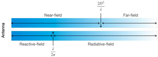
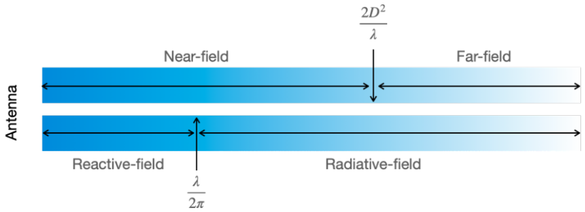
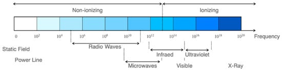
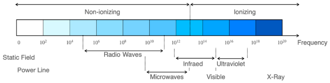

Disclaimer/Publisher’s Note: The statements, opinions and data contained in all publications are solely those of the individual author(s) and contributor(s) and not of MDPI and/or the editor(s). MDPI and/or the editor(s) disclaim responsibility for any injury to people or property resulting from any ideas, methods, instructions or products referred to in the content. |
© 2026 by the authors. Licensee MDPI, Basel, Switzerland. This article is an open access article distributed under the terms and conditions of the Creative Commons Attribution (CC BY) license.