


Abstract
Compact sub-6 GHz and wireless local area network (WLAN) multiple-input multiple-output (MIMO) antennas require broad impedance coverage and low inter-port coupling within limited footprints. This work presents a two-port Koch-fractal U-slot antenna with a defected ground structure (DGS) on RT/duroid 5880. The design evolves from a rectangular monopole through Koch-edge shaping, U-slot loading, and ground-plane defects. The fabricated two-port prototype exhibits a measured −10 dB impedance bandwidth of 3.07–6.02 GHz, covering n78, n79, and WLAN, while the measured inter-port isolation exceeds 18.13 dB. The fabricated single-element prototype provides measured realized gains of 1.92, 2.34, and 2.05 dBi at 3.5, 4.7, and 5.5 GHz, respectively. Measurement-derived MIMO metrics yield an envelope correlation coefficient not exceeding 0.002, diversity gain close to 10 dB, channel capacity loss of 0.07–0.10 bits/s/Hz, mean effective gain near −3.1 dB with zero port imbalance, and acceptable in-phase total active reflection coefficient behavior. WLAN-band quadrature phase-shift keying tests at 5.18, 5.50, and 5.825 GHz produce error vector magnitude values of 5.4–9.1%, with derived bit error rate estimates below 10−6 under an additive white Gaussian noise assumption. The design provides wide measured bandwidth, good isolation, low correlation, and WLAN-band signal-domain validation in a simple printed structure.
1. Introduction
The rapid development of fifth-generation (5G) wireless communication systems has increased the demand for compact, low-profile, and high-performance antenna front-ends capable of supporting high data rates, low latency, and reliable spatial diversity. Within the 5G New Radio (NR) spectrum, sub-6 GHz bands remain central to practical deployment because they provide a favorable compromise between propagation coverage, penetration capability, and channel capacity. In this frequency range, multiple-input multiple-output (MIMO) antenna systems are essential for improving link reliability and spectral efficiency through spatial multiplexing and diversity. However, the integration of multiple radiating elements into compact terminals inevitably increases mutual coupling, which can degrade impedance matching, radiation efficiency, radiation pattern stability, envelope correlation coefficient (ECC), diversity gain (DG), channel capacity loss (CCL), total active reflection coefficient (TARC), and mean effective gain (MEG) [1,2,3].
To address these constraints, several miniaturization and isolation enhancement techniques have been investigated, including defected ground structures (DGS), electromagnetic band-gap structures, metamaterial unit cells, metasurface superstrates, parasitic elements, self-decoupling layouts, polarization diversity, and fractal radiators [1,2,3,4,5,6]. Among them, DGS is particularly attractive for compact planar antennas because it can be implemented directly in the ground plane, without requiring additional layers or external decoupling elements. Elabd et al. [1], Karangia et al. [7], and Ali et al. [8] demonstrated that DGS-based MIMO designs can provide strong isolation improvement in sub-6 GHz 5G bands. Nevertheless, many reported configurations rely on conventional radiator geometries or additional decoupling components, leaving room for compact single-substrate solutions that combine radiator-level miniaturization and ground-plane-level isolation control.
Fractal geometries provide a complementary route to compact and multiband antenna design. Their space-filling and self-similar properties increase the effective current path within a limited physical area, thereby enabling resonant-frequency reduction and multi-resonant operation. Koch-based geometries are especially useful in this respect because successive iterations increase the electrical perimeter while preserving the overall footprint [3,4,9]. Ez-Zaki et al. [3], Ghadeer et al. [5], Sidhu and Sivia [6], and Raj and Mandal [10] applied Koch-fractal or hybrid fractal MIMO antennas to sub-6 GHz and 5G-related bands, often in combination with metamaterial, CRLH, or DGS-based decoupling mechanisms. However, these approaches may increase structural complexity, and relatively few works combine a Koch-fractal radiator, slot-based impedance tuning, and DGS-based isolation enhancement within a single compact planar MIMO structure.
Slot loading is another effective method for shaping surface-current paths and improving impedance matching without increasing the antenna size. U, S, T, ring, and elliptical-slot configurations have been used to excite additional resonant modes, broaden impedance bandwidth, and tune current distributions in compact antennas [11,12,13]. Ahmed et al. [13] and Wei et al. [14] showed that slot loading can also support MIMO decoupling when combined with proper element orientation or ground-plane modification. These studies indicate that fractal geometry, slot perturbation, and DGS can be mutually complementary, but their combined use in a compact Koch-fractal U-slot MIMO antenna for sub-6 GHz 5G operation remains insufficiently explored.
Motivated by this gap, this paper presents a compact Koch-fractal U-slot MIMO antenna with a defected ground structure for sub-6 GHz 5G and WLAN applications. The proposed design integrates three mechanisms in a single-layer Rogers RT/duroid 5880 configuration: Koch-fractal edge modification for compact multi-resonant behavior, U-slot loading for impedance tuning, and a tailored DGS for mutual-coupling suppression between the radiating elements. The antenna is evaluated using simulated and measured S-parameters, simulated far-field radiation patterns and efficiency, measured realized gain, and MIMO diversity and channel metrics derived from the simulated and measured S-parameter responses, including ECC, DG, TARC, MEG, and CCL. In addition, WLAN-band QPSK constellation and EVM measurements are included to provide signal-domain validation of the fabricated prototypes.
The main contributions of this work are summarized as follows:
(i) A compact two-port MIMO antenna topology is developed by combining Koch-fractal radiator shaping, U-slot impedance tuning, and DGS-assisted ground-current control within a single printed structure;
(ii) A physically interpretable stepwise design methodology is provided to show how each geometrical modification affects impedance bandwidth, matching behavior, and inter-port isolation;
(iii) The fabricated prototypes are characterized through measured S-parameters and realized gain, S-parameter-derived ECC, DG, TARC, CCL, and MEG, and WLAN-band QPSK constellation and EVM measurements;
(iv) A two-level benchmark is provided through comparison with representative compact 5G/WLAN/Wi-Fi MIMO antennas and with commonly adopted MIMO performance criteria.
The remainder of the paper is organized as follows. Section 2 reviews related work on compact sub-6 GHz, WLAN/Wi-Fi, fractal, DGS-based, and slot-loaded MIMO antennas. Section 3 describes the proposed antenna design methodology, geometrical evolution, MIMO extension, and prototype fabrication. Section 4 presents the simulated and measured antenna performance results. Section 5 evaluates the MIMO diversity metrics, channel-related metrics, and WLAN-band constellation response. Section 6 concludes the paper.
2. Related Work
Recent studies on compact MIMO antennas for 5G, WLAN, and Wi-Fi applications can be grouped into five main directions: compact sub-6 GHz MIMO systems, compact WLAN/Wi-Fi-oriented MIMO antennas, fractal-based radiators, DGS-based isolation enhancement, and slot-loaded or array-oriented configurations. These directions are closely related because practical MIMO antenna design requires simultaneous control of footprint, bandwidth, isolation, radiation efficiency, and diversity performance.
Compact sub-6 GHz MIMO antennas have been widely studied for mobile terminals, routers, laptops, and small wireless platforms. Chung et al. proposed a multi-coupled MIMO antenna system applicable to several electronic devices, using identical antenna elements on a single-layer FR4 substrate to support LTE, sub-6 GHz 5G FR1, and WiFi 6E operation [2]. Although the design offers broad applicability and low fabrication complexity, its isolation level remains relatively modest. In contrast, Elabd et al. introduced a compact circular MIMO antenna with DGS for 5G sub-6 GHz mobile systems, reporting a wide 3.0–6.5 GHz impedance bandwidth and strong mutual-coupling suppression within a compact 22 × 44 mm2 footprint [1]. Ahmed et al. developed slotted circular-patch MIMO configurations for sub-6 GHz 5G operation and evaluated their MIMO metrics, including ECC, DG, CCL, and TARC [13]. Similarly, Wei et al. reported a high-isolation MIMO antenna system for the n77/n78 and n79 bands using slotting and self-decoupling techniques in a smartphone-compatible configuration [14]. These works demonstrate the importance of compact planar MIMO design, but their radiator topologies generally differ from Koch-fractal U-slot configurations.
Compact WLAN/Wi-Fi-oriented MIMO antennas provide a more direct state-of-the-art comparison for the upper operating region of the proposed antenna. Göçen et al. [15] presented a 2.4/5 GHz WLAN 4 × 4 MIMO dual-band antenna box for smart white-good applications, demonstrating the relevance of compact WLAN MIMO integration in embedded product platforms. Bayarzaya et al. [16] proposed a compact two-element MIMO antenna for ISM, sub-6 GHz, and WLAN operation, achieving triple-band coverage at 2.4, 3.5, and 5.5 GHz with isolation higher than 20 dB, ECC lower than 0.003, and DG of 9.98 dB. Liu et al. [17] developed a compact 39 × 39 × 1.6 mm3 quad-port four-band MIMO antenna for 5G and WLAN applications, covering 2.6, 3.5, 4.8, and 5.8 GHz bands with inter-port isolation better than 21.5 dB, measured ECC lower than 0.012, DG of 9.94 dB, and CCL below 0.4 bits/s/Hz. Ali et al. [18] reported a compact 16 × 28 × 1.6 mm3 two-element MIMO antenna for 3.5, 5.5, and 6.5 GHz 5G/WLAN/Wi-Fi 6 devices, with isolation higher than 15 dB, measured ECC below 0.04, DG above 9.5 dB, TARC below −10 dB, and CCL below 0.4 bits/s/Hz. Awan et al. [19] proposed a dual-band 2.4/5.8 GHz MIMO antenna for communication and wearable technologies, obtaining mutual coupling below −27 dB and gains of approximately 6.2 and 6.5 dBi at 2.45 and 5.4 GHz, respectively. More recently, Mshwat et al. [20] demonstrated a compact reconfigurable four-element MIMO antenna for 3.5 and 5.2 GHz 5G/Wi-Fi applications using PIN-diode-based frequency reconfigurability, with isolation levels of approximately 25 and 21 dB, ECC below 0.0001, and DG close to 10 dB. These studies show that compact WLAN/Wi-Fi MIMO antennas commonly rely on orthogonal placement, multi-branch radiators, reconfigurable elements, or dedicated decoupling structures to preserve isolation and diversity performance. In comparison, the present work focuses on a simple two-port Koch-fractal U-slot radiator combined with DGS-based ground-current control, while additionally providing WLAN-band QPSK constellation validation at 5.18, 5.50, and 5.825 GHz.
Fractal-based MIMO antennas form a second important research direction. Paun et al. investigated Koch Snowflake-based 5G fractal antennas using fractal-theory concepts and validated their impedance, VSWR, and return-loss behavior through simulation and fabrication [4]. Ez-Zaki et al. proposed a DNG metamaterial-loaded Koch-fractal MIMO antenna for sub-6 GHz V2X communication and achieved strong coupling reduction by inserting metamaterial unit cells between the elements [3]. Ghadeer et al. developed a four-element fractal monopole MIMO antenna using Sierpiński-type radiators and a CRLH-inspired band-stop structure, obtaining wide multiband behavior and acceptable diversity performance [5]. Sidhu and Sivia combined Minkowski and Koch curves on a half-octagonal patch to realize a wideband fractal MIMO antenna with high isolation [6]. More recently, Kumar et al. reported a four-port Koch-curve fractal MIMO antenna for wideband high-isolation operation [9]. These studies confirm the usefulness of Koch and hybrid fractal geometries for bandwidth extension and compactness; however, many of them depend on auxiliary metamaterial, CRLH, or wideband structures rather than a simple U-slot radiator with DGS-based isolation.
DGS-based isolation enhancement has also been extensively investigated. Karangia et al. examined isolation improvement in a fractal-inspired MIMO antenna using ground-plane defects for 5G applications [7]. Ali et al. demonstrated that DGS could reduce coupling in circularly polarized dielectric-resonator-based MIMO antennas for sub-6 GHz 5G systems [8]. Raj and Mandal combined fractal antenna concepts with ground-defected structures for wideband 5G and prospective 6G mmWave applications [10]. These works show that DGS can effectively suppress surface-current coupling and improve MIMO figures of merit. However, the reported designs often target either dielectric-resonator, ultra-wideband, or mmWave regimes rather than a compact two-port planar antenna focused on sub-6 GHz 5G NR bands.
Slot-loaded and scalable antenna configurations provide a further basis for comparison. Sohi and Kaur introduced a slot- and SRR-loaded quad-port fractal UWB-MIMO antenna with multiple band-rejection characteristics for handheld wireless devices [11]. Jat et al. proposed a compact elliptical fractal UWB-MIMO antenna with notched radiators and a cross-stub ground modification, showing that fractal shaping and ground modification can jointly improve wideband MIMO behavior [12]. Gad et al. presented a compact S-slot antenna for 5G communications and demonstrated its extension toward MIMO operation, although the design is mainly oriented to millimeter-wave bands [21]. At the system level, Jahanbakhshi and Vertat discussed a 3D antenna-array concept for rotator-less small-satellite ground stations and advanced IoT gateways, while Otero Rebolo and Monzon Baeza benchmarked scale-up and scale-out MIMO architectures for 5G and prospective 6G networks [22,23]. These studies reinforce the broader importance of compact, scalable, and diversity-capable antenna frontends.
Overall, the literature shows that DGS-based structures offer efficient isolation enhancement, fractal radiators support compact multiband operation, and slot loading provides flexible impedance and current-path control. In WLAN/Wi-Fi-oriented MIMO antennas, compactness and isolation are commonly achieved through orthogonal element placement, multi-branch radiators, reconfigurable components, or additional decoupling networks. However, these techniques are often studied separately or combined with relatively complex decoupling infrastructures. The present work addresses this design gap by integrating a Koch-fractal patch, U-slot loading, and a tailored DGS within a single compact Rogers RT/duroid 5880 based two-port MIMO antenna intended for sub-6 GHz 5G and WLAN applications.
3. Antenna Design Methodology and Prototype Fabrication
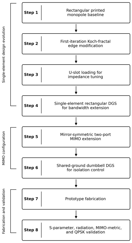
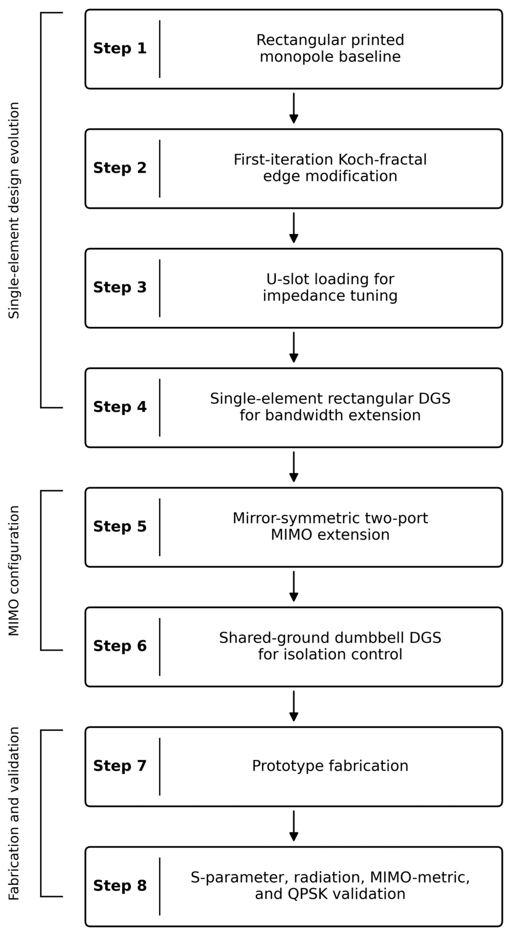
The design procedure of the proposed compact antenna is summarized in Figure 1 to provide a clear visual overview of the geometrical evolution and validation route. The procedure begins with a rectangular printed monopole, followed by first-iteration Koch-fractal edge modification, U-slot loading, single-element DGS tuning, mirror-symmetric two-port MIMO extension, shared-ground dumbbell-DGS insertion, prototype fabrication, and RF/MIMO/communication-level validation.
Figure 1.
Stepwise development and validation workflow of the proposed MIMO antenna. The downward arrows indicate the sequential progression from one design stage to the next, while the left-side brackets group the steps into single-element design evolution, MIMO configuration, and fabrication and validation phases.
As shown in Figure 1, the proposed antenna is developed through a sequential and physically interpretable design route on a single substrate stack-up. Each step introduces one geometrical perturbation to the previous configuration so that the impedance bandwidth, multi-band response, and matching depth at each operating sub-band can be associated with a specific design mechanism rather than with an unconstrained global numerical optimization. The four single-element steps are: a rectangular planar monopole on a partial ground plane (Step 1), first-iteration Koch-fractal contouring of the radiating edges (Step 2), U-slot etching in the patch metallization (Step 3), and rectangular DGS etching underneath the patch (Step 4). The optimized Step 4 element is then replicated in a mirror-symmetric arrangement to construct the two-port MIMO antenna, and a shared-ground dumbbell DGS is inserted between the elements to improve inter-port isolation. The adopted design route is intentionally sequential and physically interpretable rather than based on a global multi-objective optimizer. Each geometrical feature is introduced to control a specific electromagnetic mechanism, namely radiator miniaturization, impedance tuning, bandwidth extension, and inter-port isolation. Therefore, the proposed design should not be interpreted as a globally optimal antenna topology over all possible fractal, slot, and DGS geometries. Advanced multi-objective optimization methods may further improve the trade-off among bandwidth, isolation, gain, efficiency, and footprint; however, the present work prioritizes a compact, fabrication-friendly, and electromagnetically explainable design procedure.
The baseline antenna used in this work is the rectangular printed monopole of Step 1. This unperturbed geometry provides a clear reference response with a single dominant monopole-type resonance, allowing the effect of each subsequent modification to be isolated. The optimization strategy is physics-guided and sequential rather than based on an unconstrained global numerical optimizer. First, the baseline monopole dimensions are selected to place the main resonance close to the lower sub-6 GHz operating region. Then, the first-iteration Koch-fractal edge modification is introduced to redistribute the surface-current path and broaden the impedance response. The U-slot is subsequently added to improve input matching without increasing the footprint, while the rectangular DGS is tuned to extend the upper part of the impedance bandwidth by perturbing the ground-current distribution. After the single-element response is optimized, the element is mirrored to form the two-port MIMO layout, and the shared-ground dumbbell DGS is introduced to suppress the dominant inter-element ground-current coupling path. The design variables considered in this sequential optimization are the radiator dimensions and , feed and ground lengths and , U-slot dimensions , , , and , single-element DGS dimensions , , and , and shared-ground DGS dimensions , , and . The design objectives are |S11| < −10 dB across the n78, n79, and WLAN regions, inter-port isolation better than 15 dB, stable radiation behavior, low ECC, near-ideal DG, acceptable TARC, low CCL, and balanced MEG. Thus, the proposed approach establishes a baseline-to-final design route in which each modification has a defined electromagnetic role rather than being treated as an arbitrary geometrical perturbation.
The substrate is Rogers RT/duroid 5880 with a relative permittivity of 2.2, a loss tangent of 0.0009 at 10 GHz, and a thickness h = 1.575 mm; the metallization is 35 µm electrodeposited copper on both faces. RT/duroid 5880 is preferred over FR-4 epoxy laminate because its low loss tangent allows the antenna to retain a usable radiation efficiency in the upper sub-bands of the operating range, where the dielectric loss in FR-4 becomes the dominant efficiency limit. The substrate footprint is fixed at 30 × 30 mm2 for the single element, with an electrical area of 0.35λ × 0.35λ at the n78 center frequency. The radiator is fed by a 50 Ω microstrip line. For the chosen substrate, the microstrip feed-line width is obtained from the Hammerstad–Jensen synthesis [24] as
where . Substitution of Ω and yields mm. The feed extends from the substrate edge along the y-direction to the patch base over a length mm, and the partial ground on the opposing face shares the same length mm. From a practical implementation viewpoint, Rogers RT/duroid 5880 provides a favorable low-loss platform for validating the proposed compact wideband MIMO topology, particularly in the upper WLAN portion of the operating band. However, its cost is higher than that of commonly used FR-4 laminates. Therefore, the present prototype should be regarded primarily as a performance-oriented validation of the antenna topology rather than a final low-cost mass-production implementation. A direct transfer to FR-4 would require the retuning of the radiator, U-slot, and DGS dimensions because of the higher dielectric constant and loss tangent of FR-4, and would likely reduce radiation efficiency, especially near the upper operating band. This cost–performance trade-off is important for practical commercialization and should be considered in future substrate-level optimization.
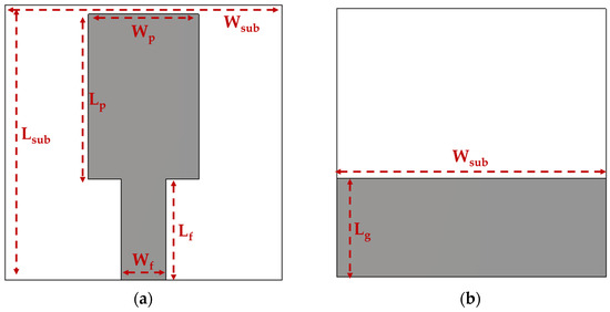
The first design is a rectangular planar monopole of length along the y-direction and width along the x-direction, fed at its lower edge by the microstrip line and electromagnetically supported by the partial ground plane. A partial rather than full ground is used because the proposed antenna is required to operate as a wide-band monopole-type radiator with predominantly vertical surface currents; a full ground would constrain the same patch to operate in the dominant TM10 patch mode, whose intrinsic fractional bandwidth is at most a few percent and is therefore incompatible with the targeted multi-band coverage. The dominant resonance of a printed planar monopole of this kind is approximated by the empirical relation of Ray [25]
where denotes the estimated resonant frequency, and denote the patch length and width, respectively, and denotes the patch-to-ground gap. Equation (2) is derived for monopoles in air; on the dielectric substrate, the resonance is shifted downward by approximately . Combining these considerations yields a target patch length of 18 mm for resonance near 3.5 GHz when mm, in agreement with the value adopted here. The top and bottom layers of the Step 1 design are shown in Figure 2.
Figure 2.
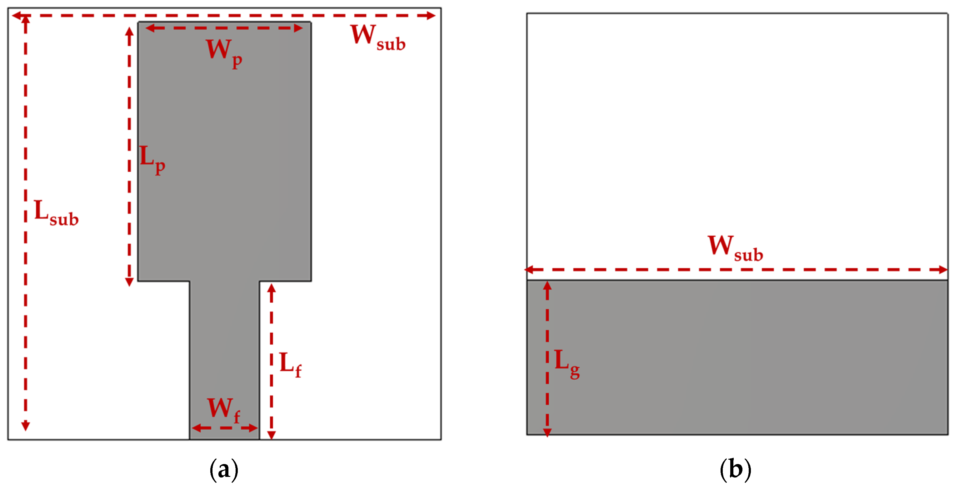
Step 1 baseline rectangular monopole antenna with geometric parameters (in mm); : (a) top and (b) bottom layers.
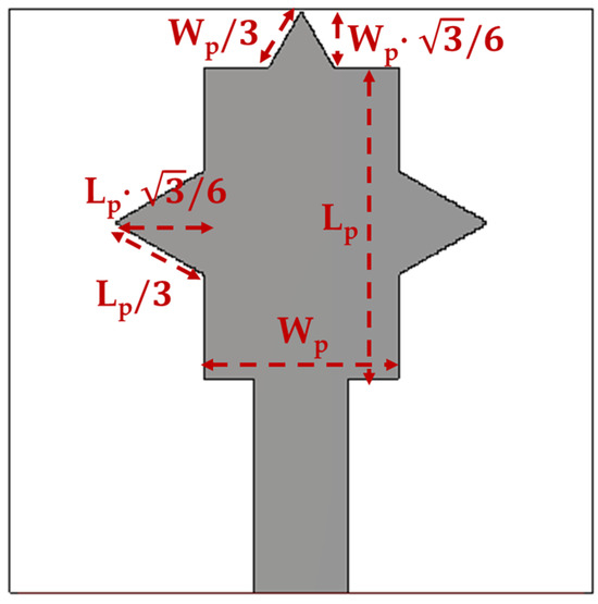
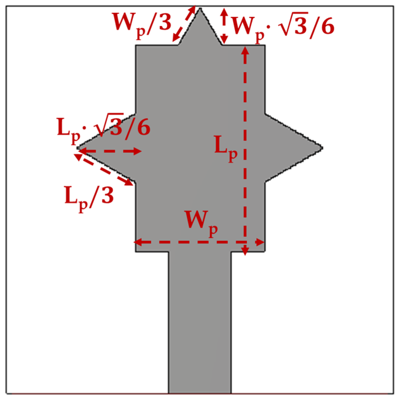
The second step modifies the radiating edges of the patch by replacing each straight edge with the first iteration of the Koch curve [26]. For each edge, the central third is replaced by the two sides of an outward equilateral triangle whose apex points away from the patch; the resulting contour has its length increased by a factor 4/3 and the apex stands at a perpendicular distance equal to (edge length) from the original line. The construction is applied to the top edge of the patch, of length , and to the two lateral edges, each of length , with the apices of the protrusions pointing outward along +y and ±x respectively. The bottom edge, which interfaces with the microstrip feed, is left straight. The use of a Koch contour on a printed monopole was first reported by Cohen [26], later analyzed systematically by Puente-Baliarda et al. [27], and reviewed within the broader fractal-antenna literature by Werner and Ganguly [28]. The contour modification has two distinct electromagnetic effects: an increase in the electrical path length seen by the surface currents that follow the perimeter, and an additional reactive loading at the corners of the protrusion that perturbs the input impedance. For a wide-aspect-ratio patch where the dominant currents traverse the interior of the radiator rather than tracing the perimeter, the bandwidth-broadening effect dominates over the geometric path-length effect; the resulting reduction in the resonant frequency is typically 5–15% per iteration rather than the 33% suggested by the geometric expansion factor. For the present design, the Step 2 patch dimensions are reduced to mm and mm. The radiator outline is then the closed thirteen-vertex polygon traced counterclockwise from the lower-left corner of the underlying rectangle, with one triangular protrusion of base and height on the top edge, and two triangular protrusions of base and height on the lateral edges. The geometric constraint that the apex of the top protrusion remains within the substrate, , fixes the upper bound mm for mm and mm. The total radiator area is approximately 189 mm2 against 216 mm2 for the Step 1 rectangular patch. The resulting fractal-edged radiator is shown in Figure 3.
Figure 3.
Step 2 Koch fractal-edge patch antenna top layer with geometric parameters (in mm); .
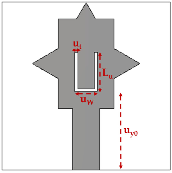
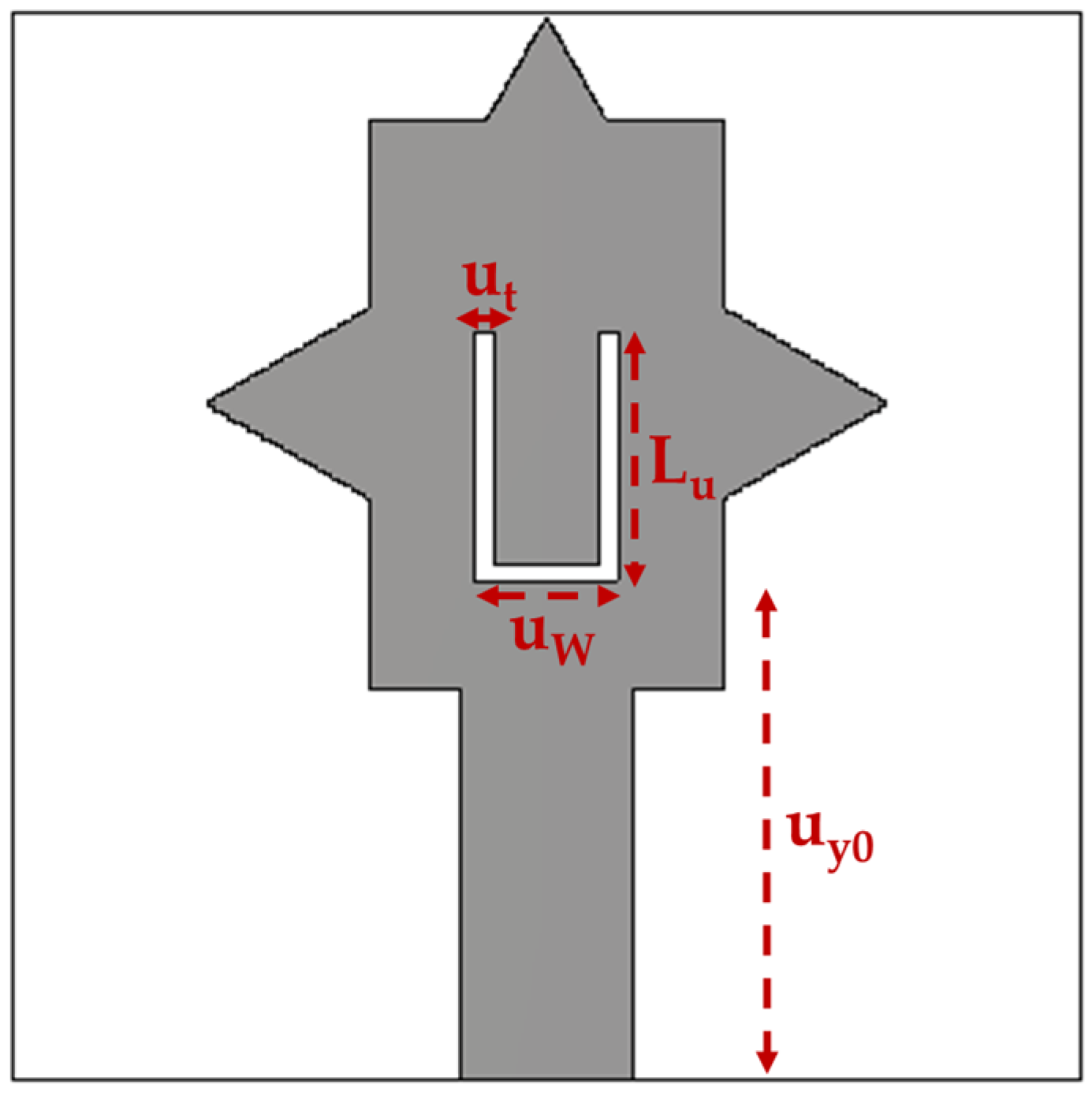
The third step introduces a U-shaped slot into the patch metallization to tune the input impedance without increasing the antenna footprint. Following the conventional U-slot antenna interpretation [29], the slot is composed of two vertical arms of length and etch width , separated by an inter-arm spacing and connected at the lower end by a horizontal slot section of the same width. The slot opens toward the upper radiating edge, while its lower connector is positioned at inside the patch. The effective centerline length is approximated as , and the effective slot permittivity is approximated as [30]. For the selected dimensions = 7 mm, mm, mm, mm, the resulting centerline length is 16.5 mm. This places the dominant slot-related resonance above the target operating bands; therefore, within the investigated sub-6 GHz and WLAN range, the U-slot mainly acts as a reactive perturbation that improves impedance matching and broadens the primary patch response rather than introducing an independent operating band. The patch with the U-slot etched into its metallization is shown in Figure 4.
Figure 4.
Step 3 Koch-edge patch with U-slot antenna top layer with geometric parameters (in mm); .
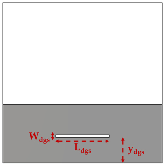
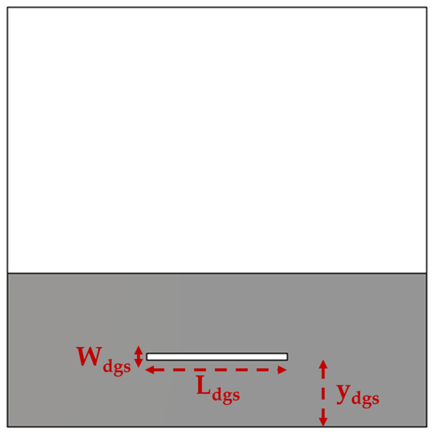
The fourth step etches a rectangular slot in the partial ground plane directly beneath the patch. A defected ground structure of this kind is conventionally modeled by an equivalent parallel LC resonator [31], where the distributed inductance originates from the slot current path and the capacitance originates from the gap capacitance across the slot edges. The corresponding stop-band frequency is
In the present configuration the DGS slot has length mm along x-direction, width mm along y-direction, and is centered at mm (3 mm above the lower substrate edge, 6 mm below the patch base). At these dimensions, the LC resonance estimated from [30] lies near the geometric center of the operating range, where the reactive loading reshapes the input impedance most uniformly. The DGS extends the impedance bandwidth into the upper portion of the operating range without introducing additional radiating modes that would compete with the patch. The Step 4 design bottom layer, including the rectangular DGS slot etched in the partial ground, is shown in Figure 5.
Figure 5.
Step 4 final single-element antenna bottom layer with geometric parameters (in mm); .
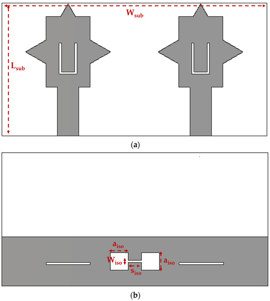
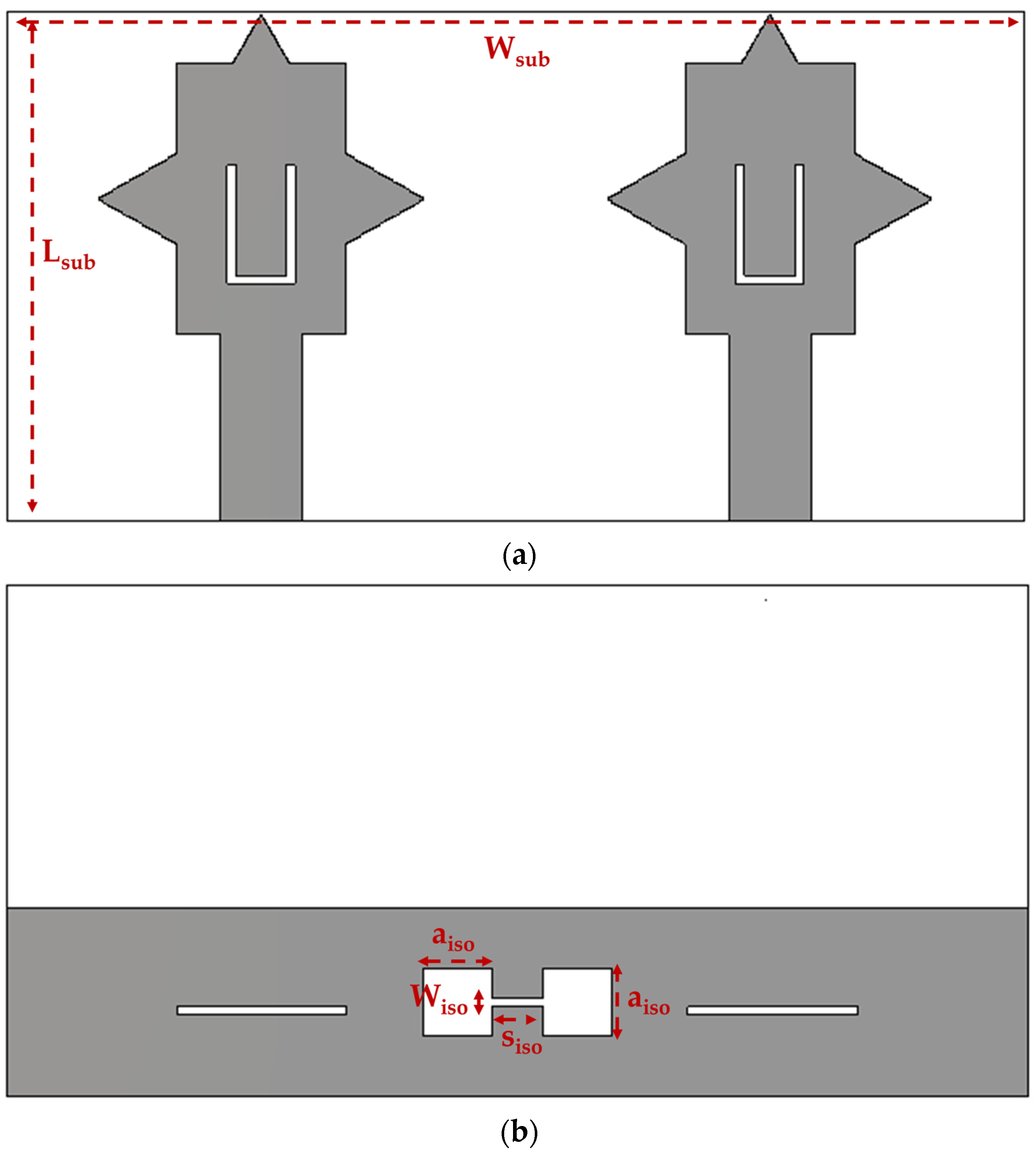
The two-port MIMO antenna is obtained by replicating Step 4’s single element in a mirror-symmetric arrangement on a shared dielectric substrate. The substrate is enlarged to 60 × 30 mm2 along x-direction to accommodate both radiators, while the substrate length is kept as mm with the same layer stack-up. The two elements are centered, giving an inter-element center-to-center spacing of 30 mm equivalent to 0.35 λ0 at 3.5 GHz. The two radiators share a single partial ground plane of length mm extending across the full substrate width, and each radiator retains the per-element DGS slot of Step 4. A dumbbell-shaped defected ground structure is etched in the shared partial ground midway between the two elements, centered at x-axis and . The dumbbell consists of two square cells of side mm separated center-to-center by mm and joined by a thin connecting slot of width mm. The structure can be represented by an equivalent parallel LC resonator [31], with the square cells contributing the dominant shunt capacitance and the connecting slot the dominant series inductance; for the chosen dimensions, the LC stop-band lies above the upper edge of the operating range, so that within the operating bands, the dumbbell acts as a reactive perturbation that reshapes the inter-element ground-current distribution without introducing a notch in the radiation response. The complete MIMO antenna design is shown in Figure 6.
Figure 6.
The proposed MIMO antenna with geometric parameters (in mm); : (a) top and (b) bottom layers.
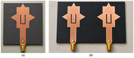
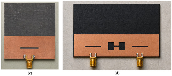
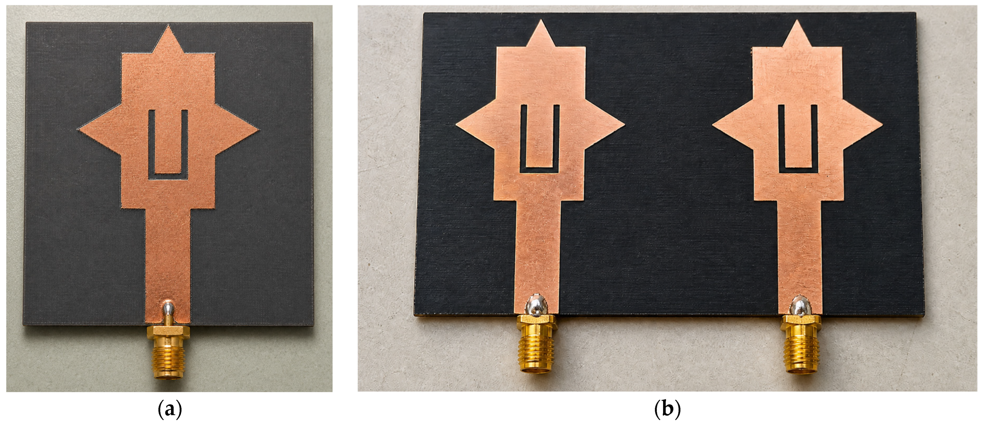
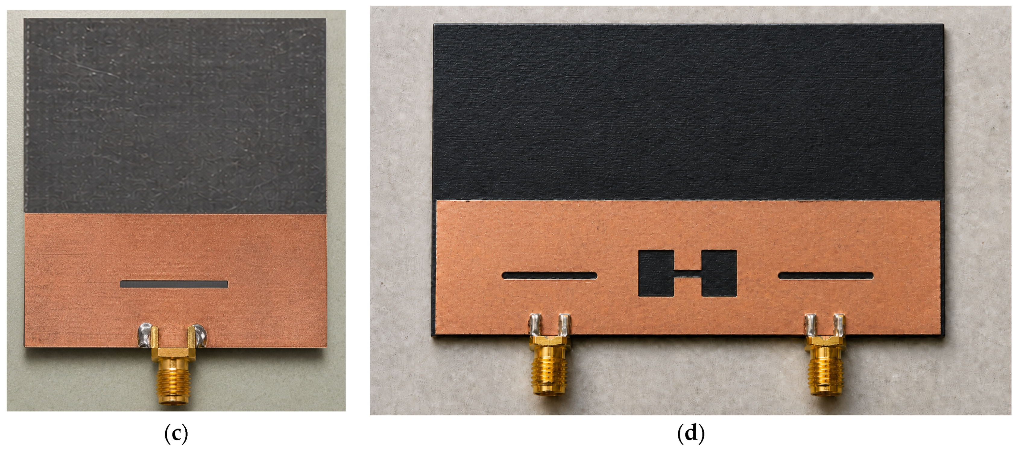
Both the single-element antenna and the two-port MIMO designs from Step 4 were fabricated in a single batch on the Rogers RT/duroid 5880 laminate. Each microstrip feed is terminated by a 50 Ω, 18 GHz end-launch SMA connector whose center pin is hand-soldered with a lead-free Sn–Ag–Cu paste, and both prototypes are subsequently mounted on a polystyrene foam holder for radiation characterization. The fabricated single element and the two-port MIMO prototypes are shown in Figure 7.
Figure 7.
The fabricated single-element prototype (Step 4): (a) top and (c) bottom layers. Fabricated two-port MIMO prototype: (b) top and (d) bottom layers.
The four-step single element, its MIMO extension and the corresponding prototypes are now fully specified; their simulated and measured antenna performances are presented in Section 4.
4. Antenna Performance Results
All electromagnetic simulations were performed in CST Studio Suite using the time-domain transient solver. The Rogers RT/duroid 5880 substrate was modeled with , , mm, and 35 μm copper metallization. The simulation frequency range was set to 2–7 GHz to cover the complete n78, n79, and WLAN regions. All ports were normalized to 50 Ω. The single-element radiation quantities, including realized gain, radiation efficiency, and total efficiency, were extracted at 3.5, 4.7, and 5.5 GHz. The fabricated prototypes were measured using a LibreVNA after SOLT calibration at the SMA connector reference plane over the 2–7 GHz range. The radiation measurements were performed in an anechoic chamber using the gain-comparison method with a calibrated standard-gain horn. During the far-field characterization, the prototype was mounted on a low-permittivity polystyrene foam holder to reduce support-induced scattering.
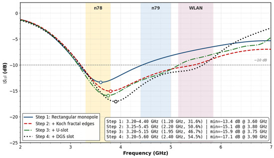
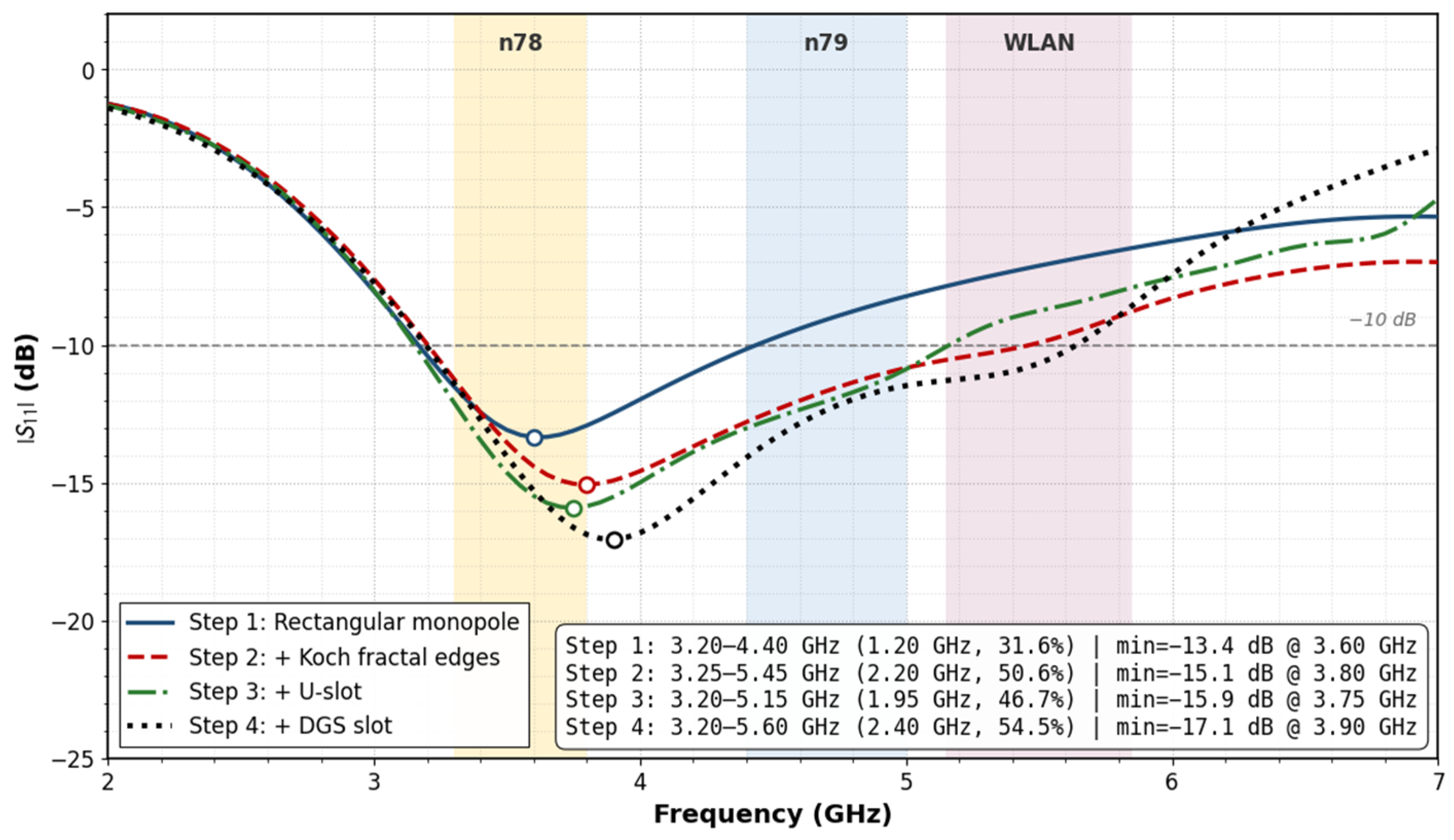
This section presents the simulated and measured impedance response of the proposed antenna. The simulated response of the four sequential single-element designs is examined first in order to attribute the impedance bandwidth and the multi-band coverage to specific geometric perturbations, after which the simulated response of the Step 4 element is compared with the measured response of the fabricated prototype, and the simulated and measured S-parameters of the two-port MIMO prototype are compared in turn. The simulated reflection coefficient results of the four sequential single-element designs of Section 3 are presented in Figure 8 to provide a quantitative baseline-to-final comparison of the proposed methodology.
Figure 8.
The simulated reflection coefficient results of the four single-element designs.
The Step 1 rectangular monopole resonates at 3.60 GHz with −13.4 dB and a −10 dB impedance bandwidth of 1.20 GHz (3.20–4.40 GHz, 31.6% fractional). The matching covers the n78 band entirely but does not extend into the n79 or 5 GHz WLAN sub-bands, confirming that the rectangular planar monopole is intrinsically a single-band radiator at the chosen footprint. Step 2 introduces the first-iteration Koch-fractal contour with reduced patch dimensions, corresponding to a 12% reduction in radiator area relative to Step 1. The simulated bandwidth extends from 3.25 to 5.45 GHz (50.6% fractional), a relative bandwidth increase of 60% compared with the rectangular baseline. The dominant electromagnetic effect of the fractal contour is the reactive loading at the protrusion corners rather than the geometric perimeter increase: the resonance frequency is preserved while the impedance characteristic is distributed over a broader frequency span that now encompasses both n78 and n79. Step 3 etches the U-slot in the patch metallization. The slot acts as a reactive perturbation that deepens the matching to −15.9 dB at 3.75 GHz, with the −10 dB band running from 3.20 to 5.15 GHz. The deeper primary dip is consistent with the U-slot operating below its half-wavelength slot resonance and contributing predominantly capacitive loading. Step 4 etches the rectangular DGS slot in the partial ground beneath the radiator. The shunt reactive loading delivered by the DGS deepens the primary dip further to −17.1 dB at 3.90 GHz and extends the upper edge of the −10 dB band to 5.60 GHz. A second pronounced dip is visible in the 5.30–5.55 GHz region which secures impedance matching across the lower portion of the 5 GHz WLAN sub-band. The Step 4 design thus achieves both the deepest matching and the widest fractional bandwidth (54.5%) of the four configurations, transforming the single-band rectangular baseline into a multi-resonant wideband radiator that covers the n78, n79 and lower 5 GHz WLAN sub-bands. This baseline-to-final evolution confirms that performance improvement is obtained through the cumulative and physically traceable effects of Koch-fractal edge modification, U-slot impedance tuning, and DGS-assisted ground-current perturbation.
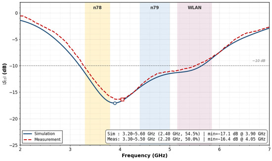
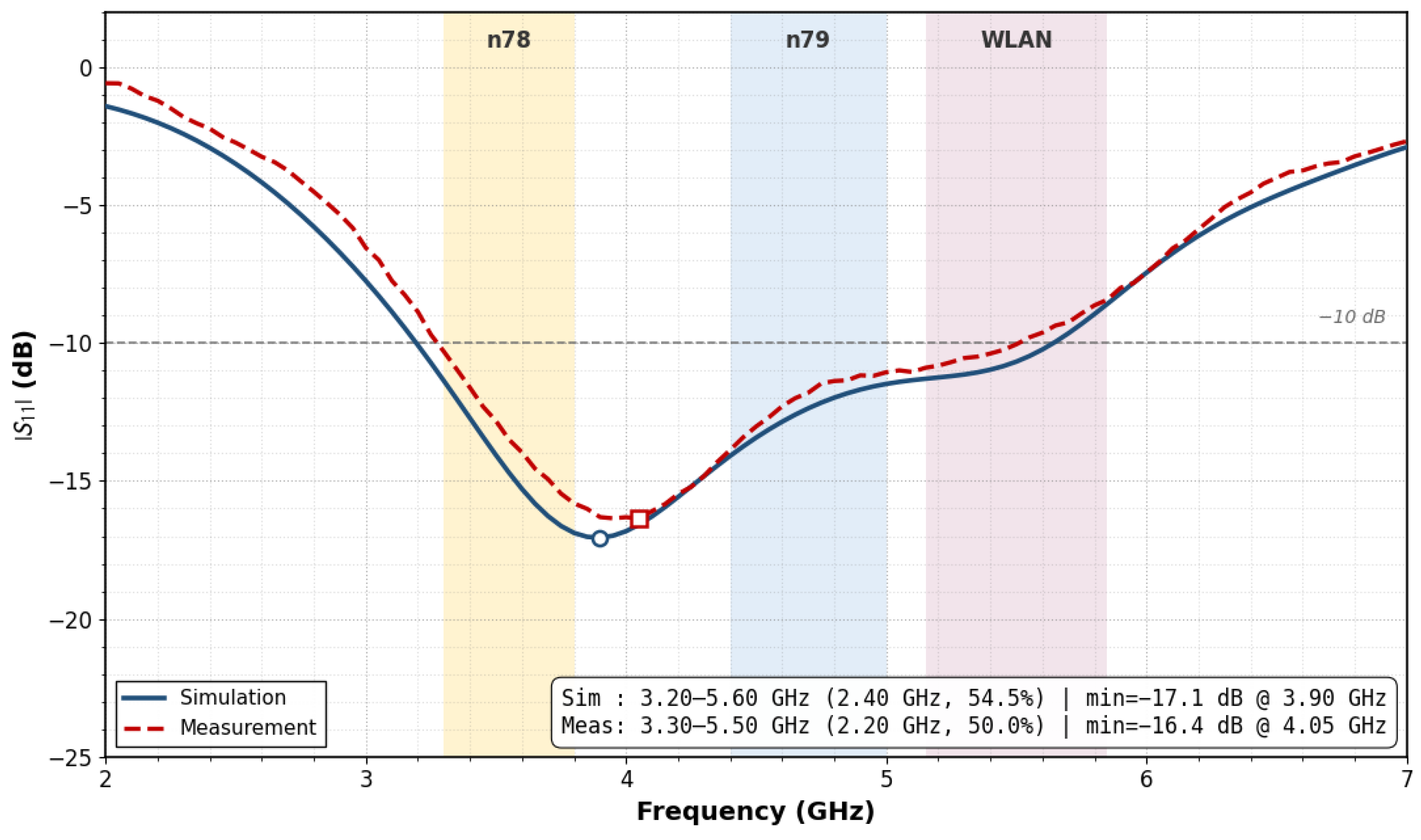
The fabricated Step 4 prototype is characterized on a VNA referenced to the SMA connector reference plane following a SOLT calibration over the 2–7 GHz range. The measured reflection coefficient is overlaid on the corresponding simulated response in Figure 9.
Figure 9.
Simulated and measured reflection coefficient results of the fabricated Step 4 single-element prototype.
The measurement reproduces the wideband multi-resonant character predicted by the simulation across the entire 2–7 GHz span, including the principal dip in the n78–n79 region and the secondary dip near the lower edge of the 5 GHz WLAN sub-band that originates from the DGS LC resonance. The dominant deviation between the two responses is a 150 MHz upward shift in the resonance frequency, well within the ±0.02 relative-permittivity tolerance specified by the laminate datasheet and the sub-50 µm copper-edge tolerance. A residual increase of approximately 0.7 dB in the reflection coefficient is attributable to the SMA connector transition, which introduces a small uncalibrated reactive discontinuity at the microstrip-to-coaxial interface. Low-amplitude ripples superimposed on the measured curve, most visible in the 4.5–5.5 GHz region, originate from secondary reflections between the connector and the radiator and are characteristic of hand-assembled microwave prototypes. The corresponding contraction of the −10 dB bandwidth from 2.40 GHz in simulation to 2.20 GHz in measurement is the combined consequence of the frequency shift and the connector-induced mismatch and remains small relative to the wideband response itself. The measured reflection coefficient stays below −10 dB throughout the n78, n79 and lower 5 GHz WLAN sub-bands, confirming the multi-band coverage predicted by the simulation and validating the four-step design methodology.
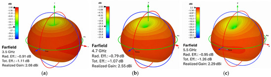
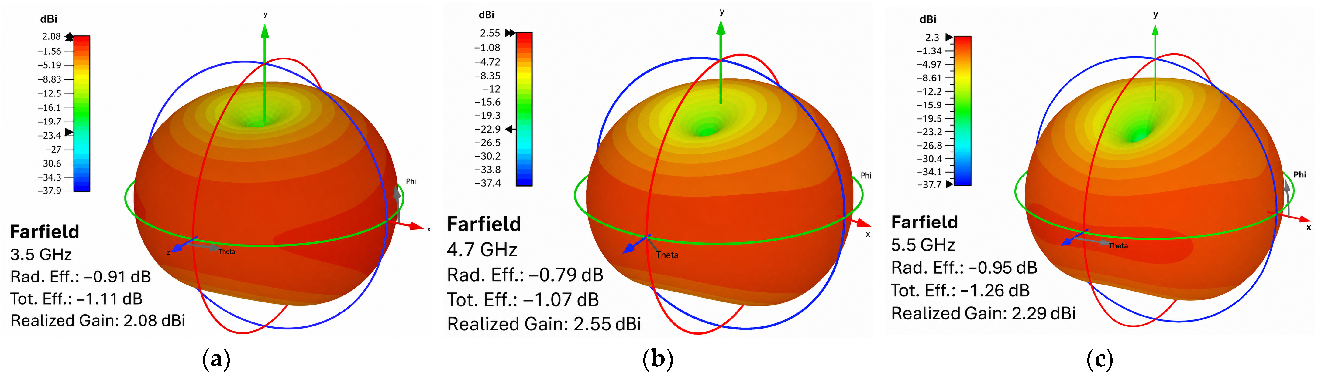
The simulated realized-gain patterns of the Step 4 element at 3.5, 4.7, and 5.5 GHz are presented in Figure 10.
Figure 10.
The simulated realized gain radiation patterns of the Step 4 single-element prototype at the three sub-band centers: (a) 3.5 GHz; (b) 4.7 GHz; (c) 5.5 GHz.
As shown in Figure 10, the simulated radiation patterns retain the expected monopole-type behavior at the three representative frequencies, with broad radiation coverage and no severe distortion in the principal radiating region. At 3.5 GHz, the simulated realized gain is 2.08 dBi, with a radiation efficiency of −0.91 dB and a total efficiency of −1.11 dB. At 4.7 GHz, the corresponding values are 2.55 dBi, −0.79 dB, and −1.07 dB, while at 5.5 GHz they are 2.29 dBi, −0.95 dB, and −1.26 dB, respectively. These values correspond to radiation efficiencies of approximately 81.1%, 83.4%, and 80.4%, and total efficiencies of approximately 77.4%, 78.2%, and 74.8% at 3.5, 4.7, and 5.5 GHz, respectively. The fabricated prototype was further characterized in an anechoic chamber using the gain-comparison method with a calibrated standard-gain horn. The measured realized gains are 1.92, 2.34, and 2.05 dBi at 3.5, 4.7, and 5.5 GHz, corresponding to deviations of 0.16, 0.22, and 0.25 dB from the simulated values. These differences can be attributed to conductor surface roughness, soldering tolerance at the SMA transition, finite connector loss, and alignment uncertainty in the measurement setup. The agreement between the simulated and measured realized gains supports the consistency of the prototype response at the tested frequencies. The three-dimensional radiation patterns and the radiation- and total-efficiency values in Figure 10 were obtained from full-wave simulations, whereas the experimental far-field characterization comprised realized-gain measurements at the three representative frequencies. Direct efficiency measurements and complete three-dimensional pattern characterization will be pursued in future measurement campaigns.
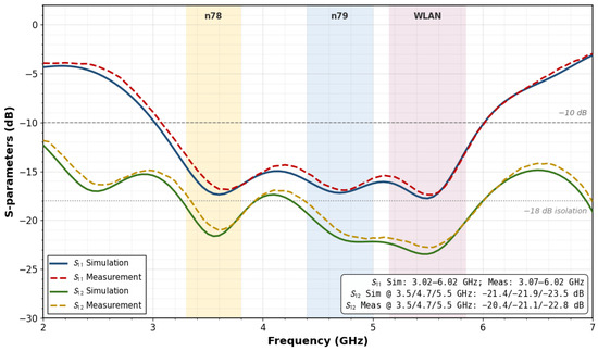
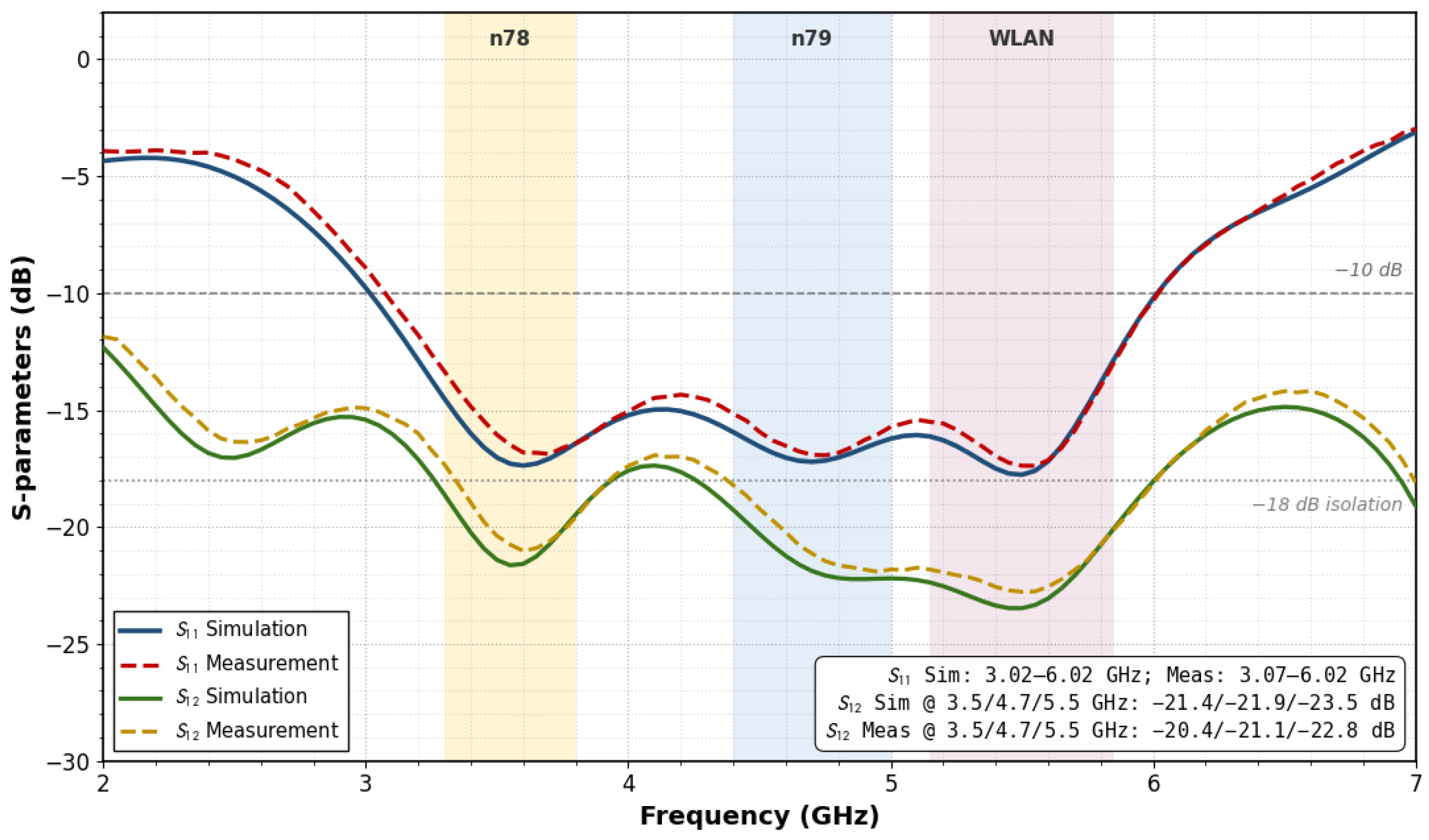
Figure 11 shows the two-port MIMO S-parameter response of the Step 4 antenna configuration. Since the final MIMO layout is geometrically symmetric, S11 and S12 are presented for clarity; S22 and S21 exhibit the corresponding symmetric responses and are therefore omitted from the plot. The results demonstrate that the two-port MIMO configuration preserves the wide impedance-matching behavior obtained in the single-element design while also providing sufficient inter-element isolation for MIMO operation.
Figure 11.
Simulated and measured S-parameter results of the fabricated two-port MIMO antenna prototype.
The simulated return loss response remains below −10 dB from 3.02 to 6.02 GHz, covering the n78 band, the n79 band, and the WLAN band. The corresponding measured response exhibits a slightly shifted but closely similar −10 dB bandwidth from 3.07 to 6.02 GHz. At the representative frequencies of 3.5, 4.7, and 5.5 GHz, the simulated reflection coefficients are −17.03, −17.21, and −17.76 dB, respectively. The measurement values are −16.06, −16.91, and −17.38 dB at the same frequencies. This close agreement indicates that the matching response is not highly sensitive to small fabrication- or connector-related perturbations. The transmission response also confirms effective coupling suppression between the MIMO elements. The simulated S12 values are −21.41, −21.88, and −23.47 dB at 3.5, 4.7, and 5.5 GHz, respectively. The corresponding measured isolation values are −20.38, −21.13, and −22.77 dB. Across the highlighted operating regions, the worst-case simulated isolation remains better than −19.27 dB, while the measured isolation remains better than −18.13 dB. These values indicate that the defected ground structure effectively suppresses the dominant ground-current coupling path without compromising the impedance bandwidth. The 10 dB impedance bandwidth of the two-port MIMO prototype (3.07–6.02 GHz, measured) is broader than that of the Step 4 single-element prototype (3.30–5.50 GHz, measured), particularly at the upper edge. Three factors contribute to this extension. First, in the MIMO layout the partial ground is enlarged from 30 × 11 mm2 to 60 × 11 mm2, which lowers the effective ground-plane inductance seen by each radiator and shifts the upper-frequency matching envelope upward. Second, the dumbbell DGS etched midway between the two elements introduces an additional shunt-reactive perturbation in the shared ground, the associated LC stop-band lies above the upper edge of the operating range, so within the band the dumbbell acts as an inductive loading that reshapes the input impedance and broadens the matching response without introducing a notch in radiation. Third, the inter-element mutual loading at 0.35 λ0 spacing modifies the per-port input impedance through the active reflection mechanism, which in this configuration further smooths the matching above 5.5 GHz. Together, these effects explain why the two-port prototype covers the upper portion of the 5 GHz WLAN sub-band (including 5.825 GHz) that lies just outside the 10 dB band of the isolated single-element radiator.
Overall, the two-port MIMO configuration maintains wide impedance matching and inter-port isolation across the targeted bands. The agreement between the simulated and measured S-parameters supports the consistency of the final layout under the fabrication and connector tolerances represented by the prototypes. Together with the simulated radiation patterns and measured realized-gain results, these findings establish the RF performance of the standalone prototype under the controlled characterization conditions used in this study.
5. MIMO Performance Results
The MIMO capability of the two-port MIMO antenna is evaluated using standard diversity and channel-performance indicators derived from the simulated and measurement-validated S-parameter responses. While impedance matching and inter-port isolation describe the RF behavior of the antenna ports, they are not sufficient alone to characterize the suitability of a compact antenna system for spatial-diversity operation. Therefore, envelope correlation coefficient (ECC), diversity gain (DG), total active reflection coefficient (TARC), channel capacity loss (CCL), and mean effective gain (MEG) are considered to quantify the correlation between radiating ports, the achievable diversity improvement, the active matching behavior under simultaneous multi-port excitation, the channel-capacity-related degradation caused by mismatch and correlation, and the mean received power balance between the MIMO ports. In addition, WLAN-band quadrature phase-shift keying (QPSK) constellation diagrams, EVM, and EVM-derived bit error rate (BER) estimates are used to assess the practical signal-domain behavior of the antenna system under representative modulation conditions. Together, these metrics provide a more complete evaluation of the proposed Koch-fractal U-slot MIMO antenna by linking its electromagnetic response to its expected communication-level performance.
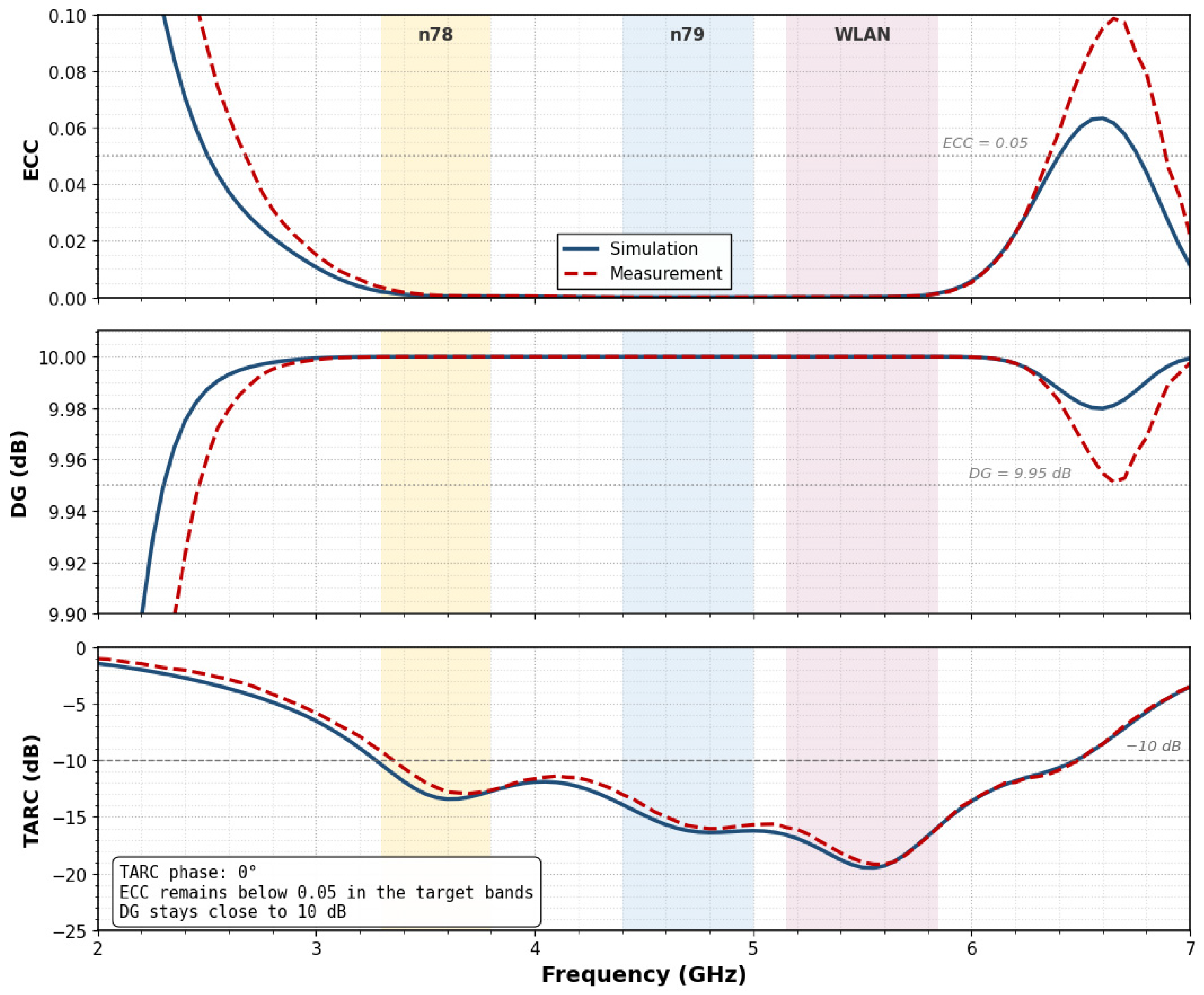
The diversity performance of the two-port MIMO antenna was further evaluated using the ECC, DG, and TARC. For the symmetric two-port configuration, S22 and S21 are equivalent to S11 and S12, respectively. The ECC was calculated from the complex S-parameters to quantify the correlation between the two radiating ports, while DG was derived from the ECC to assess the expected diversity improvement. In addition, TARC was evaluated under equal-amplitude in-phase excitation to examine the active reflection behavior of the antenna when both ports are simultaneously excited. The simulated and measured ECC, DG, and TARC responses are shown in Figure 12.
Figure 12.
Simulated and measured MIMO diversity performance of the proposed two-port MIMO antenna; ECC, DG, and TARC.
The proposed two-port MIMO antenna exhibits very low correlation over the targeted operating bands. In the n78 band, the maximum ECC values are 0.001 and 0.002 for simulation and measurement, respectively. In the n79 band, the ECC remains nearly zero, with maximum values of 0.00004 for both cases. In the WLAN band, the maximum ECC values are 0.0014 and 0.0013 for simulation and measurement, respectively. These values are far below the commonly accepted ECC limit of 0.05, confirming that the two antenna ports provide highly uncorrelated radiation behavior. The DG response remains very close to the ideal value of 10 dB across the operating bands. At 3.5, 4.7, and 5.5 GHz, both the simulated and measured DG values are approximately 10 dB, which is consistent with the extremely low ECC values. This result indicates that the proposed DGS-assisted MIMO configuration preserves strong diversity performance despite the compact element spacing. The TARC response also confirms stable active matching under simultaneous port excitation. At 3.5, 4.7, and 5.5 GHz, the simulated TARC values are −12.96, −16.21, and −19.47 dB, respectively, while the measured values are −11.94, −15.77, and −19.00 dB. The measured TARC remains close to or below the −10 dB criterion throughout the main operating regions, with only a marginal worst-case value of −9.95 dB near the edge of the n78 band. Overall, the ECC, DG, and TARC results demonstrate that the two-port MIMO antenna provides low inter-port correlation, near-ideal diversity gain, and acceptable active reflection behavior for compact sub-6 GHz 5G MIMO operation.
The communication-level behavior of the proposed MIMO antenna was additionally examined using constellation measurements in the WLAN portion of the operating band. This validation was performed with the available NI USRP-2921 software-defined radio platform, whose usable RF range covers the upper sub-band of the proposed antenna response. The NI USRP-2921 platform with its native daughterboard supports the 2.4 and 5 GHz ISM bands only and does not extend to the n78 or n79 ranges; therefore, communication-level OTA validation is restricted to three representative frequencies in the upper WLAN sub-band (5.18, 5.50, and 5.825 GHz), while the n78 and n79 regions are characterized through measured S-parameters and realized gain, supported by simulated far-field patterns and S-parameter-derived diversity metrics. These frequencies correspond to the lower, middle, and upper portions of the WLAN band, respectively, and provide an assessment of signal-domain stability under the controlled line-of-sight conditions specified in Table 1.
Table 1.
Main parameters of the WLAN-band QPSK experimental setup.
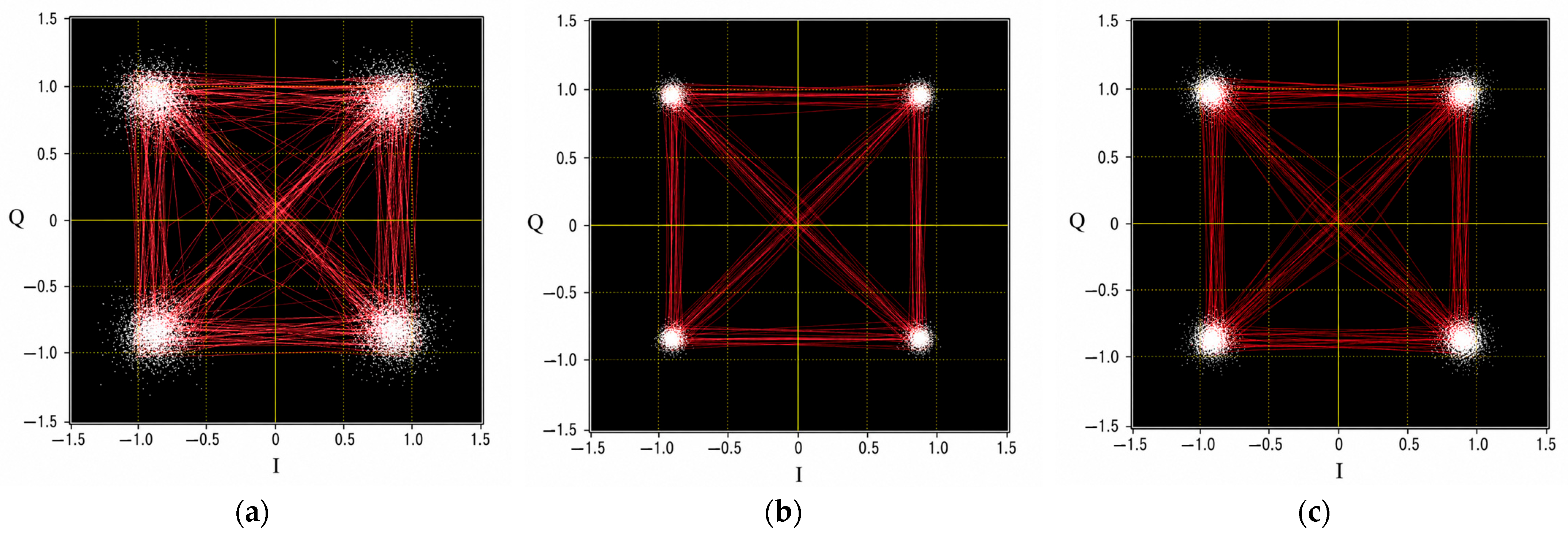
As listed in Table 1, a QPSK-modulated baseband signal was generated in LabVIEW 2011 and transmitted through the NI USRP-2921 transceiver pair connected to the fabricated antenna prototypes. The received symbols were digitally synchronized before constellation extraction, and the error vector magnitude (EVM) was computed from 10,000 received symbols at each tested frequency. Figure 13 presents the measured QPSK constellation diagrams obtained at these three WLAN frequencies.
Figure 13.
Measured QPSK constellation diagrams of the proposed two-port MIMO antenna in the WLAN band: (a) 5.18 GHz, (b) 5.50 GHz, and (c) 5.825 GHz.
The measured QPSK constellation diagrams of the proposed two-port MIMO antenna in the WLAN band confirm stable communication performance across the investigated frequencies of 5.18, 5.50, and 5.825 GHz. In all three cases, the four QPSK symbol states remain clearly distinguishable, and the transition trajectories are concentrated around the expected decision regions, indicating that the received signal preserves sufficient amplitude and phase stability for clear QPSK symbol discrimination. This result is consistent with the acceptable impedance matching, isolation, and diversity behavior reported in the previous sections. A frequency-dependent trend can also be observed in the measured constellation responses. Among the three cases, the 5.50 GHz result in Figure 13b exhibits the most compact and well-confined symbol clusters, with a measured EVM of 5.4% (−25.4 dB), indicating the lowest measured symbol dispersion within the tested WLAN band. By comparison, the constellation diagrams at 5.18 GHz and 5.825 GHz in Figure 13a and Figure 13c yield slightly higher EVM values of 9.1% (−20.8 dB) and 7.6% (−22.4 dB), respectively, consistent with the slightly larger symbol dispersion and broader transition traces visible in the plots. To provide an additional quantitative communication-level indicator, the uncoded QPSK BER was estimated from the measured EVM values under an additive white Gaussian noise (AWGN) assumption. The resulting EVM-derived BER estimates are summarized in Table 2.
Table 2.
WLAN-band signal-domain metrics of the proposed antenna.
The BER values in Table 2 were estimated from the measured EVM values under the same AWGN assumption and therefore represent analytical estimates rather than direct packet-level measurements. The values below 10−6 are consistent with the clearly separated QPSK symbol clusters in Figure 13. The communication experiment was configured to characterize QPSK operation at the three WLAN frequencies specified in Table 1; higher-order modulation schemes and standard-compliant WLAN waveforms will be examined in subsequent link-level studies.
Overall, the ECC, DG, and TARC results demonstrate that the two-port MIMO antenna provides low inter-port correlation, near-ideal diversity gain, and acceptable active reflection behavior for compact sub-6 GHz 5G MIMO operation. The channel-capacity-related behavior of the proposed two-port MIMO antenna was further evaluated using channel capacity loss (CCL). In compact MIMO antenna studies, CCL is more suitable than absolute channel capacity for antenna-level comparison because absolute channel capacity depends strongly on the propagation channel, signal-to-noise ratio, scattering environment, and channel matrix. By contrast, CCL can be calculated from the measured S-parameters and therefore provides a repeatable metric for evaluating capacity degradation caused by antenna mismatch and inter-port correlation. The measured CCL values at the representative operating frequencies are summarized in Table 3. The CCL remains far below the commonly accepted 0.4 bits/s/Hz limit, confirming that the proposed MIMO antenna maintains low channel-capacity degradation across the targeted sub-6 GHz 5G and WLAN operating regions.
Table 3.
Measured channel capacity loss values of the proposed two-port MIMO antenna.
The MEG was also evaluated to assess the mean received power balance of the two-port MIMO antenna. For a two-port antenna in a uniform multipath environment, MEG can be calculated from the measured S-parameters as
Because the proposed MIMO antenna is geometrically symmetric, the two ports exhibit nearly identical MEG behavior. The measured MEG values at the representative operating frequencies are summarized in Table 4. The MEG values remain close to −3 dB, and the MEG ratio between the two ports remains within the commonly accepted 3 dB balance criterion. This confirms that the proposed antenna provides not only low correlation, but also balanced mean received power behavior for compact MIMO operation.
Table 4.
Measured MEG values of the proposed two-port MIMO antenna.
The signal-domain results presented in Figure 13 and Table 2 complement the measured S-parameter, realized-gain, and MIMO-metric results by demonstrating stable WLAN-band QPSK symbol recovery under the specified test conditions. The prototype was characterized as a standalone antenna structure to isolate the electromagnetic contributions of the Koch-fractal radiator, U-slot loading, and DGS-assisted ground-current control. In a practical terminal, the device housing, chassis, circuit boards, batteries, display modules, connectors, nearby electronic components, surrounding objects, and user proximity may influence the input impedance, radiation characteristics, inter-port coupling, and diversity performance. Accordingly, the present experimental results characterize the standalone prototype under controlled conditions. Establishing product-level performance requires integration and user-loading studies using a representative terminal platform.
To provide a comprehensive performance benchmark, two complementary comparisons are considered. Table 5 compares the proposed antenna with representative compact MIMO antennas reported for sub-6 GHz 5G, WLAN, and Wi-Fi applications in terms of port count, antenna size, operating bands, isolation, gain, diversity and channel-related metrics, and communication-level validation. Since the compared antennas differ in operating bands, port count, topology, and intended application, a criterion-based assessment is additionally provided in Table 6 using commonly adopted MIMO performance limits.
Table 5.
Comparison with representative compact MIMO antennas for 5G, WLAN, and Wi-Fi applications.
Table 6.
Benchmark assessment of the proposed MIMO antenna against commonly adopted performance criteria.
Since the compared antennas differ in operating bands, port count, topology, and intended application, a criterion-based assessment is additionally provided in Table 6 using performance criteria commonly adopted in compact MIMO antenna studies [13,17,18].
The literature comparison in Table 5 shows that some reported antennas provide smaller footprints, higher gain, stronger isolation, or a larger number of ports at selected frequencies. Therefore, the proposed design does not outperform every reported antenna in each individual metric. Its advantage lies instead in the simultaneous provision of continuous measured impedance coverage from 3.07 to 6.02 GHz, measured isolation better than 18.13 dB, ECC not exceeding 0.002, near-ideal DG, CCL between 0.07 and 0.10 bits/s/Hz, balanced MEG, and WLAN-band QPSK signal-domain validation within a simple two-port printed configuration. As summarized in Table 6, the proposed antenna exceeds the adopted benchmarks for isolation, ECC, CCL, and MEG balance, approaches the ideal DG value, and satisfies the TARC criterion at the representative operating frequencies. The main performance distinction is therefore the balanced combination of wide measured bandwidth, low correlation, low capacity degradation, and communication-level validation rather than superiority in a single isolated parameter.
Taken together, the measured S-parameter response in Figure 11, the ECC, DG, and TARC results in Figure 12, the QPSK constellations in Figure 13, the CCL and MEG results in Table 3 and Table 4, and the criterion-based assessment in Table 6 demonstrate wide impedance coverage, low inter-port coupling, low correlation, limited channel-capacity degradation, balanced mean received power, and stable QPSK symbol recovery for the standalone prototype under controlled test conditions. Further experimental work will extend this validation to representative terminal-integration and user-loading conditions and to higher-order and standard-compliant communication waveforms.
6. Conclusions
This paper presented a compact Koch-fractal U-slot two-port MIMO antenna with a defected ground structure for sub-6 GHz 5G and WLAN applications. The antenna was developed through a four-step design procedure in which the baseline rectangular monopole was successively modified using a first-iteration Koch-fractal contour, a U-shaped slot, and ground-plane defects. The simulated two-port response remained below −10 dB from 3.02 to 6.02 GHz, while the measured response provided a comparable bandwidth from 3.07 to 6.02 GHz, covering the n78, n79, and WLAN regions. The simulated and measured isolation values remained better than −19.27 dB and −18.13 dB, respectively, across the main operating bands. The simulated radiation patterns retained the expected monopole-type behavior at 3.5, 4.7, and 5.5 GHz, while the measured realized gains at these frequencies were 1.92, 2.34, and 2.05 dBi, respectively. The S-parameter-derived MIMO results yielded ECC values not exceeding 0.002, DG close to 10 dB, CCL values between 0.07 and 0.10 bits/s/Hz, MEG values close to −3.1 dB, and acceptable TARC behavior. The WLAN-band QPSK measurements at 5.18, 5.50, and 5.825 GHz produced clearly separated symbol clusters, with EVM values between 5.4% and 9.1% and EVM-derived BER estimates below 10−6 under the specified 1 m line-of-sight configuration.
Overall, the proposed design combines wide measured impedance coverage, good inter-port isolation, low correlation, balanced MIMO behavior, and WLAN-band QPSK validation within a compact two-port printed configuration. The criterion-based benchmark further shows that the measured isolation exceeds the 15 dB reference level by 3.13 dB, the maximum ECC is limited to 4% of the 0.05 threshold, and the maximum measured CCL is 75% below the 0.4 bits/s/Hz limit, while the DG and MEG results remain close to their ideal values. The experimental characterization comprises measured S-parameters, realized gain at three representative frequencies, and QPSK constellation and EVM measurements at three WLAN frequencies, whereas the complete three-dimensional radiation patterns and efficiency results are based on full-wave simulations. The standalone-prototype results provide a basis for further development toward practical terminal integration. Future work will address multi-objective optimization of the radiator–slot–DGS geometry, implementation on lower-cost substrate alternatives such as FR-4, direct radiation-efficiency measurement, complete measured three-dimensional radiation-pattern characterization, integration into representative device housing and chassis environments, user-hand and nearby-object loading studies, and link-level testing with higher-order and standard-compliant communication waveforms.
Funding
This research received no external funding.
Data Availability Statement
The original contributions presented in this study are included in the article. Further inquiries can be directed to the corresponding author.
Conflicts of Interest
The author declare no conflicts of interest.
References
- Elabd, R.H.; Al-Gburi, A.J.A.; Megahed, A.A. Compact Circular MIMO Antenna with Defected Ground Structure (DGS) for Improved Isolation in 5G Sub-6GHz Mobile Systems. Results Eng. 2025, 27, 105737. [Google Scholar] [CrossRef] [Scilit]
- Chung, M.-A.; Huang, S.-J.; Hsu, C.-C.; Lin, C.-W. A Compact and Multi-Coupled MIMO Antenna System Applicable to Various Electronic Devices for Sub6 GHz Design. IEEE Access 2025, 13, 60387–60402. [Google Scholar] [CrossRef] [Scilit]
- Ez-Zaki, F.; Belahrach, H.; Ghammaz, A.; Ahmad, S.; Khabba, A.; Ait Belaid, K.; Ghaffar, A.; Hussein, M.I. Double Negative (DNG) Metamaterial-Based Koch Fractal MIMO Antenna Design for Sub-6-GHz V2X Communication. IEEE Access 2023, 11, 77620–77635. [Google Scholar] [CrossRef] [Scilit]
- Paun, M.-A.; Nichita, M.-V.; Paun, V.-A.; Paun, V.-P. Fifth-Generation Fractal Antenna Design Based on the Koch Snowflake Geometry: A Fractal Theory Application. Expert Syst. 2025, 42, e13242. [Google Scholar] [CrossRef] [Scilit]
- Ghadeer, S.H.; Abd.Rahim, S.K.; Alibakhshikenari, M.; Virdee, B.S.; Elwi, T.A.; Iqbal, A.; Al-Hasan, M. An Innovative Fractal Monopole MIMO Antenna for Modern 5G Applications. AEU—Int. J. Electron. Commun. 2023, 159, 154480. [Google Scholar] [CrossRef] [Scilit]
- Sidhu, A.K.; Sivia, J.S. Design of Wideband Fractal MIMO Antenna Using Minkowski and Koch Hybrid Curves on Half Octagonal Radiating Patch with High Isolation and Gain for 5G Applications. Adv. Electromagn. 2023, 12, 58–69. [Google Scholar] [CrossRef] [Scilit]
- Karangia, J.; Pandit, V.K.; Pujara, D. Isolation Enhancement in Fractal Inspired MIMO Antenna Using DGS for 5G Application. In Proceedings of the 2024 IEEE Wireless Antenna and Microwave Symposium (WAMS), Visakhapatnam, India, 29 February–3 March 2024. [Google Scholar] [CrossRef] [Scilit]
- Ali, A.; Tong, J.; Iqbal, J.; Illahi, U.; Rauf, A.; Rehman, S.U.; Ali, H.; Qadir, M.M.; Khan, M.A.; Ghoniem, R.M. Mutual Coupling Reduction through Defected Ground Structure in Circularly Polarized, Dielectric Resonator-Based MIMO Antennas for Sub-6 GHz 5G Applications. Micromachines 2022, 13, 1082. [Google Scholar] [CrossRef] [Scilit] [PubMed]
- Kumar, A.; Dewan, B.; Jain, A.K.; Rawat, P.; Zakaria, Z.; Al-Gburi, A.J.A. Design and Development of Four Port Wideband High Isolation Koch Curve Fractal MIMO Antenna. Prog. Electromagn. Res. B 2025, 112, 15–27. [Google Scholar] [CrossRef] [Scilit]
- Raj, A.; Mandal, D. Design and Experimental Analysis of Fractal Antennae with Ground-Defected Structure for Expected 6G and 5G mm-Wave Communication and Wireless Applications. Trans. Emerg. Telecommun. Technol. 2024, 35, e4900. [Google Scholar] [CrossRef] [Scilit]
- Sohi, A.K.; Kaur, A. Slot and SRR-Loaded Quad-Port, Hen-Shaped Fractal UWB-MIMO Antenna with Quad Band-Reject Ability for Handheld 4G/5G Wireless Devices. Iran. J. Sci. Technol. Trans. Electr. Eng. 2023, 47, 1187–1205. [Google Scholar] [CrossRef] [Scilit]
- Jat, N.; Kumar, A.; Ali, E.M.; Gupta, M.; Elkamchouchi, D.H.; Nanthaamornphong, A. Enhanced Isolation Unique Fractal Diminutive MIMO Antenna with Identical Elliptical Notch and Cross Stub for Wireless Uses. Sci. Rep. 2025, 15, 36600. [Google Scholar] [CrossRef] [Scilit] [PubMed]
- Ahmed, H.; Ameen, A.M.; Magdy, A.; Nasser, A.; Abo-Zahhad, M. Slotted Circular-Patch MIMO Antenna for 5G Applications at Sub-6 GHz. Telecom 2025, 6, 53. [Google Scholar] [CrossRef] [Scilit]
- Wei, X.; Lu, J.; Miao, Y.; Huang, J.; Chen, Z.; Liu, G. High Isolation MIMO Antenna System for 5G N77/N78/N79 Bands. Micromachines 2024, 15, 721. [Google Scholar] [CrossRef] [Scilit] [PubMed]
- Göçen, C.; Akdağ, İ.; Palandöken, M.; Kaya, A. 2.4/5 GHz WLAN 4x4 MIMO Dual Band Antenna Box Design for Smart White Good Applications. In Proceedings of the 2020 4th International Symposium on Multidisciplinary Studies and Innovative Technologies (ISMSIT), Istanbul, Turkey, 22–24 October 2020; pp. 1–5. [Google Scholar] [CrossRef] [Scilit]
- Bayarzaya, B.; Hussain, N.; Awan, W.A.; Sufian, M.A.; Abbas, A.; Choi, D.; Lee, J.; Kim, N. A Compact MIMO Antenna with Improved Isolation for ISM, Sub-6 GHz, and WLAN Application. Micromachines 2022, 13, 1355. [Google Scholar] [CrossRef] [Scilit] [PubMed]
- Liu, X.; Zhang, J.; Xi, H.; Yang, X.; Sun, L.; Gan, L. A Compact Four-Band High-Isolation Quad-Port MIMO Antenna for 5G and WLAN Applications. AEU—Int. J. Electron. Commun. 2022, 153, 154294. [Google Scholar] [CrossRef] [Scilit]
- Ali, A.; Munir, M.E.; Marey, M.; Mostafa, H.; Zakaria, Z.; Al-Gburi, A.J.A.; Bhatti, F.A. A Compact MIMO Multiband Antenna for 5G/WLAN/WIFI-6 Devices. Micromachines 2023, 14, 1153. [Google Scholar] [CrossRef] [Scilit] [PubMed]
- Awan, W.A.; Islam, T.; Alsunaydih, F.N.; Alsaleem, F.; Alhassoon, K. Dual-Band MIMO Antenna with Low Mutual Coupling for 2.4/5.8 GHz Communication and Wearable Technologies. PLoS ONE 2024, 19, e0301924. [Google Scholar] [CrossRef] [Scilit] [PubMed]
- Mshwat, W.F.A.; Kosha, J.S.; Salisu, A.; Ullah, A.; Ali, N.T.; Elfergani, I.; See, C.H.; Zebiri, C.; Rodriguez, J.; Abd-Alhameed, R. Compact Reconfigurable MIMO Antenna for 5G and Wi-Fi Applications. IEEE Access 2024, 12, 110283–110298. [Google Scholar] [CrossRef] [Scilit]
- Gad, M.M.; Sallam, M.O.; Ameen, A.M.; Bakr, M.H.; Soliman, E.A. Ultra-Thin Compact Bidirectional S-Slot Antenna for 5G Communications. Telecom 2026, 7, 46. [Google Scholar] [CrossRef] [Scilit]
- Jahanbakhshi, M.; Vertat, I. Concept of 3D Antenna Array for Sub-GHz Rotator-Less Small Satellite Ground Stations and Advanced IoT Gateways. Telecom 2025, 6, 92. [Google Scholar] [CrossRef] [Scilit]
- Otero Rebolo, S.; Monzon Baeza, V. A Comparative Benchmark of Scale-Up and Scale-Out MIMO Architectures for 5G and Prospective 6G Networks. Telecom 2026, 7, 38. [Google Scholar] [CrossRef] [Scilit]
- Hammerstad, E.; Jensen, Ø. Accurate Models for Microstrip Computer-Aided Design. In Proceedings of the 1980 IEEE MTT-S International Microwave Symposium Digest, Washington, DC, USA, 28–30 May 1980; pp. 407–409. [Google Scholar] [CrossRef] [Scilit]
- Ray, K.P. Design Aspects of Printed Monopole Antennas for Ultra-Wide Band Applications. Int. J. Antennas Propag. 2008, 2008, 713858. [Google Scholar] [CrossRef] [Scilit]
- Cohen, N. Fractal Antennas: Part 1. Commun. Q. 1995, 5, 7–22. [Google Scholar]
- Puente-Baliarda, C.; Romeu, J.; Cardama, A. The Koch Monopole: A Small Fractal Antenna. IEEE Trans. Antennas Propag. 2000, 48, 1773–1781. [Google Scholar] [CrossRef] [Scilit]
- Werner, D.H.; Ganguly, S. An Overview of Fractal Antenna Engineering Research. IEEE Antennas Propag. Mag. 2003, 45, 38–57. [Google Scholar] [CrossRef] [Scilit]
- Huynh, T.; Lee, K.F. Single-Layer Single-Patch Wideband Microstrip Antenna. Electron. Lett. 1995, 31, 1310–1312. [Google Scholar] [CrossRef] [Scilit]
- Garg, R.; Bhartia, P.; Bahl, I.; Ittipiboon, A. Microstrip Antenna Design Handbook; Artech House: Norwood, MA, USA, 2001. [Google Scholar]
- Ahn, D.; Park, J.-S.; Kim, C.-S.; Kim, J.; Qian, Y.; Itoh, T. A Design of the Low-Pass Filter Using the Novel Microstrip Defected Ground Structure. IEEE Trans. Microw. Theory Tech. 2001, 49, 86–93. [Google Scholar] [CrossRef] [Scilit]

Disclaimer/Publisher’s Note: The statements, opinions and data contained in all publications are solely those of the individual author(s) and contributor(s) and not of MDPI and/or the editor(s). MDPI and/or the editor(s) disclaim responsibility for any injury to people or property resulting from any ideas, methods, instructions or products referred to in the content. |
© 2026 by the author. Licensee MDPI, Basel, Switzerland. This article is an open access article distributed under the terms and conditions of the Creative Commons Attribution (CC BY) license.