


Abstract
This review analyzes recent advances in fluxgate magnetometers. It introduces an innovative concept of using magnetically ordered composite and crystalline structures made of ferrites or conducting ferromagnetic materials as fluxgate cores. These active physical media enable new multifactor excitation methods, qualitatively improving output parameters. Unlike conventional approaches restricted to magnetic permeability modulation, the authors theoretically justify processes based on the interplay of five physical factors: indirect exchange, magnetostriction, dynamic inhomogeneities, magnetoelectric interaction, and chirality. This paper systematizes original patented modulator designs. These include electrodynamic modulators implemented as compact resonant C antennas and devices utilizing the acoustic magnetoelastic effect, local magnetic inhomogeneities, or electromagnetic-acoustic excitation. Furthermore, the hardware implementation of a specialized two-component fluxgate magnetometer is considered. This device provides high-precision measurements of geomagnetic field parameters for shallow geophysical exploration and navigation systems. Experimental data confirm a significant increase in sensitivity, interference immunity, and transformation precision under extremely low power consumption. This review establishes a solid foundation for a promising applied direction at the intersection of metrology and spintronics.
1. Introduction
Magnetic field control and parameter measurement are critical and multi-level problems. This control can be implemented using magnetometers (MMs) of various types depending on the physical principles of their operation, e.g., magnetostatic, induction, quantum, etc. The MM type can be determined by the physical phenomena used to control magnetic field parameters, e.g., electromagnetic induction, as well as the Gauss, Hall, Zeeman, and Overhauser effects, etc. [1,2,3].
Various types of MMs can be used to solve a number of applied and research problems: (1) measuring the parameters of the Earth’s magnetic field and searching for magnetic anomalies in various environments; (2) shallow magnetic surveys (seismic exploration, geomagnetic survey, searching and identifying unknown metal-bearing underground objects); (3) magnetic defectoscopy and non-destructive testing of technical facility conditions; (4) navigation and orientation systems; (5) medical diagnostics (e.g., magnetic tomography); (6) solving special technical problems (e.g., non-contact measurement of large and ultra-large currents by converting their electromagnetic fields) [1,4,5,6,7,8,9]. It is obvious that the successful accomplishment of such a wide range of different tasks requires a large number of various MM types and modifications, which differ in design, excitation methods, and operating modes, magnetosensitive element operating principle, active part materials used, signal processing methods, etc.
Note that any MM contains four functional blocks (Figure 1):
Figure 1.
Functional diagram of the magnetometer.
- The primary measuring converter (PMC) based on a magnetic field probe to register magnetic field parameters and convert them into an electrical data signal;
- The excitation generator that activates the operating mode of the magnetic field probe;
- The secondary measuring converter (SMC), which is a digital block for processing the data signal, calculating magnetic-field parameters such as magnetic flux density B and magnetic field strength H, and generating the corresponding output measurement signal;
- The indication block for the output of the relevant information in a user-friendly form over an external interface.
The functional capabilities and specifications of MMs are determined by the parameters of the measuring converters and, primarily, the magnetic field probe. Covering the entire range of existing MMs and ways of their improvement within one paper appears unfeasible. Therefore, the authors focused on the MM group, referred to as fluxgate magnetometers (FM), which use a fluxgate (FG) as the magnetic field probe. Compared to other magnetic field converter types, the FMs can facilitate simultaneous measurement of several magnetic field components over a wide range of operating temperatures. They have high sensitivity and low power consumption, as well as high reliability and resilience to external impacts, and lower costs.
An FG is a device sensitive to an external magnetic field, both constant and slowly changing. As a rule, it has a ferromagnetic core, an excitation system (excitation winding), and a measuring winding. Its operation is based on the non-linear properties of core materials and the interplay of the external measured field and the auxiliary alternating field generated by the excitation system in the core. As a result of this interaction, an electromotive force (EMF) proportional to the measured magnetic field arises in the measuring winding at the output. The value of this EMF is a data signal used for the assessment of the external magnetic field parameters. However, there is almost no FG operating property improvement potential left within the conventional approach to FG operation based on the magnetic modulation conversion of the magnetic permeability of the ferromagnetic core due to the alternating magnetic field generated by the excitation winding current.
This research analyzes a new approach to the FG design based on the use of magnetically ordered physical structures made of ferrimagnetic materials (ferrites) as FG cores. The use of ferrite materials as an active physical medium provides an opportunity to convert external physical fields (e.g., alternating electric field) into fields of other physical origins (e.g., perform the mutual transformation of elastic, mechanical, and electromagnetic fields). This will help not only change process parameters for the magnetic modulation of their magnetic permeability due to the intrinsic magnetic properties of ferrite, but also provide an opportunity to simultaneously initiate additional physical effects during the resonant impact of respective physical fields. As we will see, the use of ferrites can help excite, for instance, an acoustic field with radial primary waves that undergo additional acoustic modulation of the magnetic core’s magnetic permeability within their structure.
Thus, the use of ferrites, including conducting ferrites, will help implement additional new FG excitation methods. This article analyzed a number of FG options that implement different multifactor excitation methods based on the fact that ferrites are active magnetically structured physical structures that may feature complex self-organization forms. Additionally, we studied the FG excitation methods and systems and described the transition from multiturn excitation windings to small resonant capacitive-type radiating antennas (C antennas) that operate as an electrodynamic modulator. Radiating C antennas may not only significantly improve the thermal stability of FG operation but also help reduce their size through the use of high-tech solutions.
Thus, the main purpose of the paper is not just to review the known FM and FG but also to describe and analyze the new excitation methods and designs in which the modulation of the magnetic permeability of the magnetic circuit is carried out simultaneously through the use of various physical effects, which ensures an increase in the sensitivity and accuracy of FGs. This work presents various FG design options with improved metrological properties and analyzes the physical processes occurring inside FGs.
2. Analysis of Magnetic Field Probe Parameters
2.1. Key Types of Ferromagnetic Elements
A ferromagnetic element is a key component of any ferromagnetic converter. According to their operating principles or the ferromagnetic core property used, all ferromagnetic elements or devices can be divided into the following three groups [1,3,10,11]:
- Parametric ferromagnetic elements;
- Magnetic modulation elements;
- Hysteresis elements.
Uncontrolled ferromagnetic elements are parametric if their operation is based on the use of the non-linear nature of the core magnetizing curve. These elements use the dependence between the electrical circuit parameters containing a ferromagnetic core winding and the value of the form and frequency of the winding voltage and current.
As a rule, only an alternating magnetic field operates inside parametric element cores. But in some specific cases, there is also a permanent field that is normally used to set the initial magnetic condition of the core.
The cores of magnetic modulation elements are typically subjected to at least two magnetic fields with varying frequencies, one of which is commonly generated by the AC power source and the other by input (control) signals. These elements are controlled ferromagnetic devices whose operation is based on the fact that one of the magnetic fields changes (modulates) the magnetic condition of the other field’s core.
Hysteresis elements use the hysteresis of ferromagnetic materials during operation. These elements may not operate normally when there is no hysteresis.
Of the ferromagnetic element groups listed above, magnetic modulation devices are of the greatest interest for FM. Their operation is based on the following: a ferromagnetic core can be used to provide a special type of connection between two electric circuits, where the amount and type of current change in one of the circuits controls (modulates) the electric processes in another circuit. The fundamental nature of this ferromagnetic link can be illustrated by the simplest magnetic modulation element, whose schematic is shown in Figure 2.
Figure 2.
The schematic of a magnetic modulation element with decoupled winding circuits.
In this circuit, windings w1 and w2 are positioned perpendicularly so that the currents passing through them produce perpendicular magnetic fields in space (spatial field separation). This winding positioning on the core can be implemented by using a toroidal core with an internal circular slot for the installation of one of the windings (w1), while the other winding (w2) can be installed over the core and perpendicular to the first winding.
One of the windings (w1) is series-connected to the AC voltage source U1 with frequency f, and the other winding (w2) is connected to the DC control voltage source Uy. AC voltage U2 is registered on the terminals of winding w2 through the decoupling capacitor C. If Uy = 0, AC voltage U1, connected to winding w1, is not transformed to winding w2, because windings w1 and w2 are positioned perpendicularly, and there is no transformer coupling between them.
If Uy ≠ 0, AC voltage U2 ≠ 0 with double frequency 2f is registered on the terminals of winding w2, whose value is directly proportional to the control signal Uy, which implies a ferromagnetic coupling between windings w1 and w2 (magnetic modulation effect).
Summing up, the magnetic modulation element with the same design as shown in Figure 2 includes two different but closely related ferromagnetic coupling phenomena. The first phenomenon suggests that the AC i1 in winding w1 causes frequent changes in the differentiated magnetic permeability μd of the core. Therefore, if winding w2 has DC creating a permanent magnetic field with intensity H0, the magnetic flux Φ caused by it will change along with the magnetic permeability μd. Magnetic flux changes induce an EMF in winding w2 whose value is directly proportional to the intensity of the permanent field H0. Another phenomenon is that the permanent (or slowly alternating) current in winding w2, in turn, has a significant impact on the inductance value of winding w1 and therefore on the average value of current I1, passing through the winding and resistance R1.
2.2. Ferroinductive Converters
Ferroinductive converters (FICs) are widely used to solve a wide range of scientific and applied problems. These converters are devices sensitive to external constant and slowly changing magnetic fields, containing ferromagnetic cores and windings distributed along their length.
A ferromagnetic core made of a soft magnetic material is the sensitive element of the FG sensor. Its magnetic permeability µ changes under the combined action of two fields: the excitation field generated by the excitation winding and the external measured field. The change in µ, proportional to the value of the measured field, is recorded as an EMF in the measuring winding.
Three basic methods of exciting the ferromagnetic core of an FG sensor are known: mechanical, thermal, and magnetic excitation (Figure 3).
Figure 3.
Ferroinductive converters with mechanical (a), thermal (b), and magnetic (c) excitation.
In mechanical excitation of an FG sensor, a quartz plate with a thin ferromagnetic film deposited on it, for example, a permalloy film, is used as the excitation element (Figure 3a). When an electric voltage at the resonant frequency is applied to the quartz plate, it begins to periodically change its dimensions due to the converse piezoelectric effect, which, in turn, causes a periodic change in its magnetic permeability. Since the measured magnetic field also acts on the core, an EMF e(Bi) proportional to the induction of this field is induced in the measuring coil. However, FG sensors with mechanical excitation of the ferromagnetic core have relatively low sensitivity because of the small range of variation in magnetic permeability.
In thermal excitation of an FG sensor, a low-inertia thermal injector is used as the excitation element. It is in direct contact with a thin ferromagnetic plate made of a material with a low Curie point (Figure 3b). If direct and alternating currents are simultaneously passed through such an injector, the temperature of the plate will pulsate near the Curie point, which will lead to pulsation of magnetic permeability. Under the additional action of an external magnetic field, the EMF induced in the measuring coil will be proportional to this field. FG sensors with this excitation method provide higher sensitivity than sensors with mechanical excitation, which makes it possible to measure weak magnetic fields. However, their manufacture requires materials with specific properties, which complicates FG sensor fabrication and increases the dependence of accuracy on external conditions.
FG sensors with magnetic excitation are called fluxgates. They use the non-linear properties of ferromagnetic materials (Figure 3c). To excite such FG sensors, a signal, usually sinusoidal, is applied to the excitation winding wound around the ferromagnetic core. The alternating current in the coil creates an alternating magnetic field that periodically changes the magnetic permeability of the core. The varying magnetic flux induces an EMF in the measuring coil, which, in the absence of an external measured field, varies according to a harmonic law. When an external field appears, the harmonic composition and parameters of this EMF change in direct proportion to the intensity of the measured field, generating a corresponding signal in the measuring coil. This signal makes it possible to monitor the amplitude, frequency, and direction of the intensity vector of the measured magnetic field. These properties are the advantages of fluxgate transducers compared with FG sensors using other excitation methods.
For all types of FG sensors, the equation for the EMF induced in the measuring winding has the following form [1]:
where is the unit vector coinciding with the winding turn plane; w is the measuring winding turn number; is the cross-sectional area of the core in the direction; is the relative permeability tensor of the core material; and B0 and H0 are the measured magnetic flux density vector B0 and magnetic field strength vector H0.
At the same time, due to a number of positive qualities, the most widely used FICs are those containing a fluxgate sensor.
2.3. Fluxgate Structure
In the general case, the FG consists of an excitation winding and a measuring winding on a ferromagnetic core (Figure 3c). Sometimes, both functions are performed by the same winding.
The excitation winding is connected to an alternating voltage U(t) that provides the alternating current saturating the core. On the measuring winding, alternating voltage e(B1) is measured for the analysis and measurement of the external magnetic field B1. Thus, the operation of a fluxgate is based on the following: one of the magnetic field modules measures the magnetic state of the ferromagnetic core for the other field.
FGs are active devices, and processes in them are always associated with the existence of two fields: the measured external field and the auxiliary excitation field generated by the current passing through one of the windings. The interplay of these fields in the cores causes an EMF to emerge in the other winding. Since the core parameters are non-linear, this EMF value depends significantly on the intensity of the external magnetic field. This allows using the EMF magnitude to evaluate the intensity of the external field. Modern FMs support magnetic induction measurement within a range of 100 pT to 1 mT, and their conversion function non-linearity reaches up to 0.001%. The operating temperature range may range from –180 °C to + 220 °C [12].
Figure 4 shows a standard structural flowchart for an FM using an FG.
Figure 4.
Standard FM structural flowchart.
The excitation winding of the FG receives, for example, a high-frequency sinusoidal signal from the current generator. The signal on the FG measuring winding output contains information about the measured magnetic field Bi, and it is amplified and sent to the selective amplifier or synchronized detector set for the second harmonic frequency of the excitation signal. The identified signal is filtered by the low-pass filter and sent to the registration device, measuring the direct voltage, which is calibrated in units of magnetic flux density.
Based on the waveform, two main types of excitation signals are distinguished: sinusoidal and pulsed [13,14,15]. Pulsed excitation involves applying short pulses to the winding: either bipolar pulses that cyclically alternate in polarity (rectangular, sawtooth, or triangular in shape) or unipolar pulses that maintain a single polarity. Each excitation type has its own specific characteristics, advantages, and application areas, as the excitation waveform determines the nature of the core’s magnetization reversal and the output signal spectrum, thereby defining key magnetometer characteristics: sensitivity, linearity, power consumption, and circuit complexity [16]. Sinusoidal excitation is commonly used in classic circuit designs employing synchronous detection of the second harmonic, which ensures maximum sensitivity and low noise levels. Pulsed excitation, offering reduced power consumption, is utilized in portable and autonomous devices. Accordingly, sinusoidal excitation is selected for precision laboratory and scientific applications where sensitivity and stability take precedence over size and power consumption, whereas pulsed excitation is chosen for portable, industrial, and autonomous applications where efficiency, compactness, and noise immunity are the critical factors. Rectangular excitation is used for high-frequency operation (where thorough filtering is also required); sawtooth excitation is employed when zero-level stability and linearity are critical; and triangular excitation is used for precision measurements where minimizing error is paramount.
Several FG designs use the rod and toroidal core geometries (Figure 5): single-element rods (Figure 5a,b); open-core differential (Figure 5c); closed (toroidal) core differential (Figure 5d) [1,3].
Figure 5.
Main fluxgate types: (a,b) single-element rods; (c) open-core differential; (d) closed (toroidal) core differential.
Rod-type: single-element fluxgates may have either one winding that combines the functions of the excitation winding and the measuring winding, from which the information signal e2(t) is taken, for example, in the form of the second harmonic (see Figure 5a), or two independent windings (Figure 5b). A rod-type differential fluxgate has two identical rod cores, each of which has its own excitation winding, while the measuring winding usually encloses both cores (Figure 5c) [17,18,19,20]. Obviously, differential fluxgates are structurally more complex than single-element ones; however, they have higher sensitivity and reduce the influence of interference due to the series-opposing connection of the excitation windings, which creates fields of opposite directions in the cores [21].
Ring-core fluxgates have a toroidal ferromagnetic core on which the excitation winding and the measuring winding are placed (Figure 5d) [22,23,24]. To enable simultaneous measurement of two magnetic field components, two measuring windings are placed on the core, with their axes arranged mutually perpendicular to each other.
Rod-type fluxgates are simple to implement and provide minimal demagnetization of the rods, since the measured field H0 is directed along the rod axis. However, ring-core fluxgates provide a lower noise level due to the uniform distribution of mechanical stresses in the ring core, as well as the possibility of balancing the output signal by rotating the core inside the measuring winding. In addition, differential two-rod fluxgates are difficult to tune, since they require a high degree of identity between the two rod cores.
Depending on the relative orientation of the external magnetic field strength vectors and the excitation magnetic field, FGs are classified as having longitudinal (parallel) and transverse (orthogonal) excitation [25,26]. In Figure 5a, the exciting magnetic field H~, generated by the excitation current i1(t), is orthogonal to the probed magnetic field H0 (transverse excitation), while in Figure 5b,c, the exciting magnetic field H~ is directed along the core axis parallel to the probed magnetic field H0 (longitudinal excitation). In turn, in Figure 5d, closed, counter-directed exciting magnetic fields H~ are generated in the ring core, lying in a plane parallel to the probed magnetic field H0.
It should be noted that any of the FG types shown in Figure 5 use the two-module functional structure: (1) modulator consisting of the structured ferromagnetic system (core) and emitting (exciting) element (excitation coil) wb; (2) recorder consisting of the receiving (measuring) inductance coil wi. In the FG, the measured external field with intensity H0 directly impacts the ferromagnetic cores of the modulator. The same cores are affected by the alternating field H~, generated by the current i1(t) of the modulator’s excitation coil wb. Intensities H0 and H~ can be converted to the alternating magnetic flux density B(t) = B [H~, H0] and then to e2(t) = e2 [B(t)], emerging in the measuring coil wi, using the same techniques as for the magnetic amplifier.
Of particular interest are the design solutions for FGs with closed cores and with spatially combined measuring and exciting coils, i.e., when the exciting coils are located inside the measuring coil (Figure 6) [27]. Figure 6a shows a longitudinal-type excitation FG, in which the exciting magnetic field Hex is parallel to the probed magnetic field Hdc (the excitation current Iex propagates in a plane orthogonal to the core axis). Figure 6b shows a transverse-type excitation FG, in which the exciting magnetic field Hex is located circumferentially and orthogonally to the probed field Hdc (the excitation current Iex is directed along the core axis).
Figure 6.
FGs with closed cores and with spatial combination of coils: longitudinal (a) and transverse (b) types.
In FGs with longitudinal excitation, the exciting field Hex is parallel to the measured field Hdc. These FGs have the following structural features:
- The presence of a ferromagnetic core in the form of an elongated ring with primary windings distributed along its length, located inside a common secondary winding;
- They have the inverse connection of primary windings, which facilitates an almost-zero EMF in the secondary winding when there is no measured field Hdc. When the measured field exists and therefore disrupts the balance between the fluxes in the first and the second cores, the secondary winding achieves an EMF proportional to the longitudinal component of the external field, which is used to generate the output information signal Vout.
In FGs with transverse excitation, the exciting magnetic field Hex is orthogonal to the measured field Hdc. The specific design features of these FGs are as follows:
- A permalloy tube is used as the core, in which the alternating current of the primary winding creates a circular magnetic field (transverse to the longitudinal axis of the tube) that periodically magnetizes it;
- The measuring winding is aligned with the longitudinal axis of the tube. When there is an external field, an EMF is induced in it, and an output signal Vout is generated.
2.4. Operating Modes of Fluxgates
As mentioned above, FGs differ by the operating mode, auxiliary field induction method, and design [1,28].
For instance, we can study a differential fluxgate with parallel fields, which uses the sum of two fields from two independent sources as the auxiliary alternating field.
where H2 is the intensity of the permanent (non-measured) magnetic field; Hm is the amplitude intensity value of the exciting alternating magnetic field.
H1(t) = Hm·sinωt + H2,
When calculating the output EMF of a fluxgate sensor, the non-linear magnetization curve of the core is typically approximated by a truncated third-degree polynomial [1,28]. In this case, we can write the following for a fluxgate with parallel fields (measured permanent magnetic field H0 = const ≠ 0):
where s and w are the total cross-sectional area of the fluxgate core and the number of turns in the measuring winding, respectively; b is the approximation factor that depends on the magnetic properties of the core and is determined experimentally for each specific type of ferromagnetic material.
e(t) = 6·b·s·w·H0·(2·H2·Hm·cosωt + H2m·sin2ωt),
It can be seen that in this type of differential FG, it is possible to implement two basic operating modes.
In the first mode, the excitation circuit of the fluxgate passes weak alternating and relatively strong direct currents. The alternating current generates the field H1, which is so small that it almost does not affect the differential permeability of the cores μ*d. The direct current, on the contrary, generates the field H2, which modulates the μ*d. Normally, the H2 field is selected so that the working points of the cores are on the steepest slopes of the μ*d (H) function. Figure 7a shows the working point in A. The measured field H0 is algebraically summed with H2, moving the working point in section DE, reducing the differential permeability in one of the cores and increasing it in the other one.
Figure 7.
Dependencies of μ*d (H) and μ*d (ωt) in the first (a) and second (b) fluxgate operating modes.
Due to the different permeabilities of the cores, the balance of inductances is disrupted, which causes the induction of EMF in the secondary winding of the fluxgate, which is proportional to the imbalance value and, consequently, to the measured field value:
e(H0) = 12·b·s·w·H0·H2·Hm·cosωt.
In the second mode, the fluxgate excitation circuit only passes the alternating current. The amplitude of this current is such that its generated field H1 = Hm·sinωt, and it periodically saturates the core magnetically. The measured field H0 is so small that its presence has no significant effect on core magnetization. The schematic fluxgate operation in this mode is shown in Figure 7b.
If Hm > Hs, where Hs is the core saturation field, then μd* fluctuates periodically from the maximum (when H1 = 0) to the minimum (when H1 = Hm). The frequency of these changes doubles because μd*(H) = μd*(−H), and they induce a double frequency EMF e(H0) in the secondary winding of the fluxgate:
e(H0) = 6·b·s·w·H0·H2m·sin2wt.
The second mode has a number of advantages over the first one. The key advantage is an even-harmonic output signal, which can improve the signal/noise ratio because the noise caused by the fluxgate imbalance in the second mode is characterized by the odd-harmonic spectrum of EMF. Another advantage of this mode is the stability of the fluxgate zero. In addition, note that the main advantage of magnetometers employing the double-frequency method is that no fluctuations of power source voltage, differences in core size or parameters, temperature changes, etc., may cause double-frequency voltage on the fluxgate output when there is no measured magnetizing field.
Depending on the winding coupling method and the functional purpose, there can be two fluxgate types: fieldmeters and gradiometers. The schematics of the gradiometer fluxgate and fieldmeter fluxgate only differ by the connection direction of both windings in one of the coils (Figure 8).
Figure 8.
The schematics of a fieldmeter fluxgate (a) and a gradiometer fluxgate (b).
These schematics use the inductive method with longitudinal excitation. The fieldmeter FG can be used to test the presence and intensity of the magnetic field, while the gradiometer FG can measure the intensity gradient of the magnetic field between different points.
The exciting windings of the fieldmeter FG feature the series-inverse connection, and the measuring windings use the series-consistent connection. When there is a permanent magnetic field, harmonics are induced in the sensing circuit whose amplitude is proportional to the intensity of the measured permanent field.
In a gradiometer FG, primary windings are connected in series and form an excitation circuit, while the secondary windings are connected inversely and form a sensing circuit. If the coils are affected by the same alternating fields and the same permanent magnetizing fields, the indicator circuit output EMF will be equal to zero. If the constant component of the magnetic field is different in both coils, this will induce EMF in the secondary winding.
Since FGs measure magnetic field strength, which is a vector value, their operation is characterized by a directional diagram. When the directions of the intensity vectors of the external magnetic field and the FG field are aligned, the output signal of the FG is at its maximum. When the vector directions are perpendicular, the signal is at a minimum. The FG directional diagram in the geomagnetic field in two different planes is shown in Figure 9 [29].
Figure 9.
Fluxgate directional diagram: HT, HH, and HZ are the full vector and the horizontal and vertical geomagnetic field components, respectively.
The directional diagram allows using FG to measure the magnetic field strength components and the magnitude of the total magnetic field vector (when the fluxgate core axis is aligned with the magnetic field).
3. Specific Aspects of Ferrite Core Use
The sensitivity of FGs depends heavily on the magnetic properties of their cores [30]. The sensitivity (conversion factor) of FGs can be improved by increasing the core excitation frequency. The operating FG core excitation frequency is determined by the magnetic properties of the material they are made of. Generally, FG cores are made of soft magnetic materials. Conventionally, permalloys are used for this purpose. These are alloys of iron and nickel with high magnetic permeability and low coercive force [1,2,24,28]. This material provides FGs with a number of advantages: high sensitivity, heat stability, resistance to radiation, reliable operation, and low cost. Low coercive force facilitates easy magnetization and demagnetization of permalloys. However, in this case, FGs require thorough calibration.
Currently, permalloys are being supplanted by amorphous magnetic alloys [31,32,33,34], providing FGs with improved metrological and operational characteristics. This is achieved due to the high magnetic permeability of cores made of such materials, low remagnetization losses, and stability of magnetic properties after mechanical shocks and deformation; in this case, the cores may be manufactured in the form of ribbons [35] or wires [36]. However, FGs made of these materials have high magnetic noise levels, which can be attributed to magnetoelastic interaction: mechanical oscillation resonances are excited in the core, and the strong magnetomechanical coupling generates acoustic noise, which is added to the natural magnetic noise [37,38]. Also, such FGs have an unstable zero, causing unpredictable changes in the output signal level [39].
In addition to the aforementioned materials, single-crystal epitaxial films of yttrium–iron garnet and substituted garnets can be used to fabricate fluxgate cores [40]. Their fundamental difference from Permalloy and amorphous metals—where magnetization reversal occurs via the nucleation and motion of domain walls (a stochastic process accompanied by Barkhausen jumps)—lies in the fact that magnetization reversal is achieved through the coherent (uniform) rotation of the magnetization vector within the film plane driven by a rotating magnetic field, rather than by domain wall motion. In garnet cores, due to uniform and stable magnetic anisotropy throughout the material volume, the magnetization vector rotates coherently without local “pinning” at defects, thereby enhancing fluxgate sensitivity. These materials possess a very low damping parameter, a factor that directly determines the minimum detectable field level. However, their fabrication technology (particularly that of epitaxial films) is significantly more complex and costly. Furthermore, garnet cores can be brittle; substantial mechanical stress (such as impact, vibration, or excessive clamping) may cause cracking or chipping, which degrades fluxgate performance and limits their range of applications.
In summary, fluxgates with cores made of Permalloy or amorphous alloys represent the standard choice for applications requiring high magnetic permeability and soft magnetic properties. Such FGs are used in magnetometry (for measuring the geomagnetic field in geological exploration, studying space magnetic fields, and in navigation and industrial automation systems, etc.), in flaw detection (for locating surface and subsurface defects), and in thickness measurement (for measuring the thickness of non-magnetic coatings). Garnets are selected when ultra-high sensitivity and low noise levels are paramount, for instance, in precision magnetometers for medical research [41]. Fluxgate sensors with such cores represent an emerging field that could potentially replace SQUID sensors in applications requiring ultra-high sensitivity without cryogenic cooling. However, to date, traditional ferromagnetic cores remain the only viable option for the mass production of FGs requiring proven reliability and established manufacturing technology.
As shown before, the operation of available FGs with the aforementioned types of cores is based on the modulation of the dynamic magnetic permeability of the magnetic core due to the auxiliary alternating magnetic field, which helps convert the zero-frequency signal carrying information on the measured permanent field into the domain of higher frequency, particularly into the domain of the second harmonic spectral line. However, the possibilities of improving the metrological properties of FGs by any optimization of the magnetic modulation transformation of magnetic permeability have objective limitations.
A qualitative leap in the performance of fluxgates is possible based on new physical principles of their operation through the use of ferrimagnetic materials (ferrites) for their cores, with a corresponding design change to the excitation system. This is based on the fact that ferrite cores are actually active physical systems that can be represented as a set of several subsystems that interact with each other and in which complex forms of self-organization can arise:
- Bistable subsystem (where transition from one stationary state to another is implemented as a response to the external impact of a certain intensity);
- Excitable subsystem (where active transition to another state and subsequent return to the balanced state occur when an external impact exceeds a certain threshold);
- Self-oscillation system (which performs constant cyclic transitions over a set of states where external impact may only slow down or accelerate this motion, but not stop it).
Such active media feature various autowaves, i.e., unattenuated wave processes supported by the energy from external sources. Furthermore, active media with periodic boundary conditions may have traveling waves and respective multistability manifested in the presence of several stable balanced states (attractors) for the same set of parameters.
Ferrites can be represented as a model with two subsystems: (1) a dynamic subsystem that models the reception of the impact from the external alternating electric field and activation energy feed; (2) a dissipation subsystem that models the conversion capacities of the active physical medium. In this case, the dissipation subsystem is assumed to be two-level, where the energy dissipation is studied separately in the main active and structural elements of the ferrite workpiece. The dynamic subsystem, in turn, has a finite number of degrees of freedom and discrete energy levels. The dissipation subsystem features an infinite number of degrees of freedom and a continuous energy spectrum.
When developing FG using new physical principles, various physical factors can be used that can be activated in their ferrite cores: indirect exchange interaction; magnetostriction; dynamic inhomogeneities; magnetoelectric interaction; chirality.
3.1. Indirect Exchange Factor
Atomic electrons participate in the generation of the atom’s magnetic field in two ways: firstly, electrons themselves have some magnetic properties, i.e., they have a magnetic spin moment, and secondly, electrons form a cloud around the atom’s core, which generates a magnetic orbital moment. Spin and orbital moments are summed (vector addition) to generate the magnetic moment MJ of the atom or ion [42,43].
In the development of FG, special attention is paid to the indirect exchange via conduction electrons. The mechanism of this exchange relies heavily on the assumption about the exchange interaction s–d(f), which implies there are two groups of electrons in magnetic materials: 1—localized electrons of uncompensated d- or f-shells of atoms; 2—collective electrons of valence (s, p, …) energy bands responsible for electric properties and contributing the most to magnetism. Due to the s–d(f) exchange, conduction electron spins are magnetized (polarized) by localized d- and f-electrons. Since s–d(f) interaction depends on the direction of spins, conduction electrons with different spin directions react differently to s–d(f) exchange. Conduction electron polarization caused by the spin of one 4f atom located at point Rn affects the spin of another 4f atom at point Rm, i.e., they implement an indirect exchange link between the 4f atoms [43,44]. Thus, the s–d(f) exchange interaction can cause oscillatory spin polarization of conduction electrons. Therefore, the alternating electric field has an impact on the oscillatory nature of the spin polarization of conduction electrons.
3.2. Magnetostriction Factor
There is also another related magnetoelastic effect: changing the parameters of a magnetically ordered substance due to a magnetic field, i.e., the magnetostriction effect. The magnitude of this magnetoelastic interaction is determined by the dependence of atomic spacing on exchange interactions and the interactions of electronic magnetic layers of ions with local electric fields. Real-life ferro- and antiferromagnets have a multi-domain structure with an anisotropic magnetostrictive deformation (i.e., spontaneous magnetostriction) in each domain [45].
Thus, the impact of magnetic ordering on elastic properties is manifested in magnetoelastic effects that contain key information on magnetoelastic interactions in solid bodies, dependence on the atomic spacing of the electron structure, and exchange and magnetocrystalline interactions.
Many magnetoelastic effects are promising in terms of their use in various areas of technology, and some of them, e.g., magnetostriction, have already been extensively used [38,46,47,48,49,50].
3.3. Dynamic Inhomogeneities Factor
Apart from the considered magnetoelastic properties, magnetically ordered media have other effects attributed to dynamic inhomogeneities [51,52,53]. Functional magnetoelectronics may be cited as an example; it studies magnetoelectronic effects and phenomena in magnetically ordered continuous media, with considerable attention given to the phenomenon of static inhomogeneity. A static inhomogeneity is a localized region on the surface of a medium or within its volume that differs in its properties from the host medium. Owing to the unique characteristics of static inhomogeneities, which make it possible not only to generate various electromagnetic processes but also to control them, corresponding sensor devices can be developed. Particular attention is attracted by so-called dynamic inhomogeneities of magnetoelectronic nature, which are indirectly associated with electrons. In fact, a dynamic inhomogeneity is a localized volume without static inhomogeneities inside it, formed as a result of certain physicochemical processes. Such a region may be either fixed or mobile within the working space of the continuous medium, changing its position under the influence of various physical fields or interacting with other dynamic inhomogeneities of similar or different nature. The motion of a dynamic inhomogeneity is accompanied by active field interaction with the sensitive elements of sensors, which opens up opportunities for their practical application.
At the same time, dynamic inhomogeneities of different physical nature may be conventionally divided into three main types. First, these are wave dynamic inhomogeneities, such as surface acoustic waves, magnetostatic waves, space-charge waves, and charge-density waves. Second, these include ensembles of charged particles and quasiparticles, including charge packets of electrons and fluxons. Third, this group may include domains of different physical nature, such as ferroelectric domains, Gunn domains, and cylindrical magnetic domains. Such types of dynamic inhomogeneities are of considerable interest for the development of sensor solutions and for improving the efficiency of modern electronic devices.
Based on this, we suggest forming a periodic domain structure (PDS) in a magnetically ordered structure by exposing it to an alternating electric field with a specific configuration, i.e., the potential formation of a spin-wave acoustic oscillator initiating s–d(f) interaction processes due to exposure to an alternating electric field affecting the structural elements of the magnetically ordered substance. In this case, we can use a permanent magnet made of rare-Earth material Sm-Co as a magnetically ordered workpiece with a sufficient number of transition-element atoms, as it has a spatially stable magnetizing vector. Basically, this involves the development of a spin-wave acoustic generator operating on the basis of the oscillating magnetoelectric polarization signal, caused by the shift in spin charges due to the alternating electric field. This spin-wave acoustic generator can be developed through the following sequence of operations:
1. Building up a magnetically ordered structure in the ferromagnetic element by exposing it to a permanent magnetic field of a magnet.
2. Initiating cyclic formation of dynamic inhomogeneities as PDS in the magnetically ordered structure of the ferromagnetic element by exposing this structure to an inhomogeneous alternating electric field with a specific spatial configuration.
3. Forming domains of stable acoustic wave generation through the implementation of spin-wave dynamic processes.
The induced domains effect is of special interest. It is the possibility of using external impacts to create domains with required configurations and form a domain-shifting structure (DSS) out of them. These induced domains and DSS may be dynamic, i.e., have a capacity for spatial or temporal restructuring depending on the intensity or nature of external impacts. Another external impact may involve acoustic waves that can induce dynamic DSS in homogeneously ordered magnetics. When a traveling acoustic wave propagates in the magnetic material, the induced domain structure will shift along the workpiece at the same speed as the wave, and when the standing wave is excited, the DSS will have a stable spatial distribution determined by the period of this standing wave. When the requirement that the anisotropic energy should significantly exceed the exchange energy is satisfied, a previously magnetically ordered homogeneous workpiece will be broken into specific domains with alternating magnetization directions (along or across the acoustic wave propagation direction).
3.4. Magnetoelectric (ME) Interaction Factor
Among magnetic materials, ferrites occupy a special place. They are produced using ceramic technology and, in fact, belong to one class of piezomagnetic ceramic materials. Therefore, ferrites can be considered composite materials that consist of mechanically interacting mixes of magnetostrictive and piezoelectric components (subsystems). Based on their properties, they can be classified as magnetoelectric materials, whose main effect is the ME, i.e., the induction of electrical polarization in the material due to an external magnetic field or the magnetization due to an external magnetic field. In addition, ferrite workpieces are polycrystalline domain structures, correlated systems where the orientation of the magnetic moments of the domains in one part of the crystalline structure affects the orientation of the magnetic moments of the domains in adjacent regions of the crystalline structure, thus turning the entire workpiece into a self-organized system. Since the ME effect in composites is associated with the mechanical interactions of the piezoelectric and magnetostrictive systems, the amplitude of the ME effect increases dramatically in the electromechanical resonance domain.
Note that the physical properties of composite structures consisting of two or more phases are determined by the properties of each phase and their interactions, i.e., the composite may have properties that are absent from its component materials.
The qualitative direct and converse ME effects (DME and CME) in these composites can be described by the following expressions:
| DME effect | = | Electrical properties | × | Mechanical properties | . |
| Mechanical properties | Magnetic properties | ||||
| RME effect | = | Magnetic properties | × | Mechanical properties | . |
| Mechanical properties | Electrical properties |
To sum up, the interaction between the magnetic (spin) and elastic subsystems may result in the emergence of linked magnetoelastic oscillations in the magnetic subsystem. In this case, the mechanical interaction of subsystems produces a ME in the ferrite rods of fluxgates (composite ferrite-piezoelectric materials), which may reach values that exceed their low-frequency value by several orders of magnitude in the electromechanical resonance domain. This provides new opportunities for its practical use. Note that the problems of designing ME probes made of composite materials have received significant attention [54,55,56,57].
3.5. Chirality Factor
A ferrite core is a composite medium understood as a macroscopic inhomogeneous system consisting of components that typically have clear interfaces. Such components may differ in their structure, geometry, and physical parameters, including electrodynamic properties: σ—conductivity, ε—dielectric permeability, and μ—magnetic permeability. Because of this, the material of the FG ferromagnetic core can be considered an artificial chiral medium consisting of two inset cubic symmetry lattices, where the nodes of one lattice contain ferrite spheres and the nodes of the other one contain electric dipoles with lumped inductance.
During the interaction of the electromagnetic field and a chiral medium, in addition to parameters ε, μ, and σ, we can also study the material parameter χ, which stands for chirality. Its physical meaning is that it determines the degree of interconnectedness of electrical and magnetic polarization processes in a chiral medium [58]. Unlike ordinary magnetic materials or dielectrics, chiral media contain elements with mirror asymmetry, meaning that they cannot be superimposed on their mirror image. The chiral parameter χ characterizes the degree to which this mirror asymmetry is manifested in the medium, and its value depends on the concentration of chiral elements in the medium, their geometric dimensions, and other factors. Numerically, the chiral parameter χ is proportional to the ratio of a/λ, where a is the linear size of an electromagnetic particle of the medium and λ is the wavelength. When a/λ → 0, the chiral properties of the medium disappear. For the chiral medium in question that contains the simplest structural electromagnetic particles of elements, material equations look as follows (Lindell–Sivola equation [59]):
where and are the electric and magnetic induction vectors.
Since there is a component proportional to in , it means that the current induced by the alternating magnetic field in chiral elements induces not only a magnetic dipole moment but also an electric dipole moment. The properties of these chiral media are described in detail in [60], which demonstrates that the implementation of the normal operation of FG requires an excitation option in the ferromagnetic core of a standing H wave involving the exposure of its chiral structure to an alternating electric field. In this case, the interaction between the alternating electric field and the chiral medium initiates three linked electrodynamic processes:
1. The emergence of chiral magnetization due to an external electric field ;
2. The formation of chiral polarization due to a magnetic field , induced by chiral magnetization;
3. The formation of a magnetic-type standing wave (H wave) through the evolving process of electrodynamic interaction of chiral magnetization and chiral polarization.
Therefore, magnetic waves are excited in the ferromagnetic core with chiral properties, whose magnetic field has a longitudinal component, and the electric field is oriented perpendicularly to the propagation direction. Thus, when the structure of a solid chiral ferrite waveguide is exposed to a lateral alternating electric field, a corresponding modulating standing magnetic wave will be excited in it:
The presence of this standing magnetic wave, in turn, will result in the respective modulation of magnetic permeability μ of the chiral medium of the waveguide:
where μ0 is the permeability of the medium without the modulation wave; mμ is the small modulation index; kμ is the wavenumber of modulation.
The polycrystalline ferrite composite structure possesses a latent chirality, which acts as an intrinsic, emergent property. Even if individual grains and their crystal lattices are achiral, an effective chiral medium arises from the collective organization of grain boundaries, defects, domain structures, and statistically non-equivalent spatial distribution of residual stresses.
Resonant excitation of this polycrystalline structure by an external alternating electric field activates the collective dynamics of its structural and magnetic inhomogeneities. This transforms the latent chirality into an observable state, triggering a cascade of interrelated multiphysics effects (magnetoelastic, magnetoelectric, and electromagnetic-acoustic) that manifest in the material’s magnetodynamic response.
Based on the analysis of the properties of a ferromagnetic FG core, we can conclude that it is a complex hierarchical system characterized by several structural elements and links between them. In this case, the functioning of this system will be based on a multitude of interrelated physical effects (PE) determined by the presence of the five previously reviewed physical factors. The PE themselves are typically manifested when the physical system in question or its structural elements transit from one stable state to another.
Thus, the presence of five physical factors indicates an opportunity to expose the structural elements of a ferromagnetic core to specific physical fields that, in turn, may react to this exposure by inducing specific PEs that can be grouped as follows: conductors, modifiers, energy converters, and physical object converters. By initiating specific groups of PE manifestations, we can form FGs based on new operational principles to provide higher operational quality indicators.
4. Fluxgate Excitation Methods
4.1. Conventional Fluxgate Excitation Methods
Any fluxgate contains a modulator as its main functional unit, which excites and modulates the external magnetic field being measured. It consists of a structured magnetic core and an excitation element. When there is no external magnetic field being measured, the core is remagnetized under the action of the modulator in a symmetrical cycle, inducing in the measuring winding an EMF that varies harmonically. If the core is exposed to a measured magnetic field (permanent or slowly changing), the core remagnetization curve becomes asymmetrical. Because of this, the value and harmonic composition of the EMF change, and even harmonic components appear in it, whose magnitude is proportional to the intensity of the measured field.
To change the magnetic state of the magnetic core of a fluxgate modulator, various methods of exciting fluxgates with different orientations of the measured and auxiliary alternating magnetic fields are used. Fluxgates use galvanic and inductive excitation methods for the alternating magnetic field. These methods differ by the field source type and electromagnetic field generation peculiarities [28].
The galvanic FG excitation method requires changing the magnetic state of the magnetic core by the modulator. In this process, the core is exposed to a circular alternating magnetic field perpendicular to its longitudinal symmetry axis. The source of this field is the alternating electric current passing over the entire length of the ferromagnetic core. Thus, this method uses mutually perpendicular magnetic fields (measured permanent magnetic field and alternating auxiliary magnetic field), which provide the decoupling of the power circuits and the FG output.
The drawback of this method is the occurrence of two disturbing factors: significant temperature instability of the physical and design parameters of the FG and dynamic degradation processes in the ferromagnetic core materials. The simultaneous impacts of these factors on the fluxgate have a cumulative effect on the overall fluxgate time instability, which ultimately reduces the measurement precision. The requirement of direct electrical contact with the ferromagnetic FG core creates specific design and technological problems for the implementation of the galvanic excitation method.
The inductive FG excitation method requires changing the magnetic state of the magnetic core by the modulator. In this process, the magnetic core is exposed to an alternating magnetic field aligned with its longitudinal symmetry axis. The source of this field is the alternating electric current bypassing the emitting dipole element implemented as a multiturn coil and covering some of the ferromagnetic core length.
The drawback of this excitation method is that it cannot provide the required measurement precision due to the destabilizing temperature factor caused by the passing of the excitation current via the multiturn coil. The presence of a multiturn excitation coil in the modulator is a source of additional interference, which significantly complicates the design and performance of fluxgate production. Additionally, FGs with a multiturn excitation coil are oriented to implement the set-conductivity current mode, i.e., the set excitation field intensity mode, where significant energy losses and instability of both component parameters and zero readings of the device are inevitable. Note that to achieve high FG sensitivity, the excitation coil is generally made with a greater number of turns, which helps improve the magnetic flux value of the auxiliary field, which is involved in the inductance of the EMF in the measuring winding. This, however, complicates the device structure. Even the transition to single-layer coils suggested in [61] or the use of the same coil for excitation and measurement [62] cannot eliminate the mentioned drawbacks.
The analysis of the research and technical literature shows that works aimed at improving fluxgate parameters mainly consider improving the properties of their ferromagnetic cores [30,63,64], as well as enhancing the quality of information signal processing [65,66]. Apart from this crucial problem, however, the developers of such devices face the problems of improving the operational properties of the excitation element (excitation magnetic field source) and upgrading the structural design.
4.2. New Fluxgate Excitation Method
The analysis of research, technical, and patent documentation showed that the popular FG types mainly use the inductive excitation method for the alternating magnetic field, which features a number of critical drawbacks.
To improve the efficiency of operation and technical specifications of FG, the authors considered a new FG excitation method with a new type of modulator that creates an auxiliary alternating electric field required for the initiation of magnetic permeability modulation for the ferromagnetic FG core. They suggest using an emitting C antenna as this modulator.
The presence of the displacement current joff = εadE/dt is one of the features of the system generating electromagnetic emission whose intensity is characterized by the intensity of the electric field in an environment with absolute dielectric permeability εa [67]. In this case, the example concentrator of the flux lines for the displacement current joff is a common capacitor with lumped capacitance C, excited with a long line. The antenna based on this condenser can be considered a capacitor-type antenna (C antenna). In terms of the operating principle, the C antenna is close to the EH antenna, where the formation processes for the electric E component and the magnetic H component of the electromagnetic emission are separated. The respective changes in the power circuit of the C antenna allow for its conversion into an EH antenna, where the current phase delay of 900 between the current and the voltage from the power source can ensure the required phase synchronism of the generated fields E and H. This property of the EH antenna allowed for the development of a new antenna type with new properties where the H field is formed by the offset currents through the antenna capacity.
As a rule, the EH antenna is designed to significantly narrow its directional diagram in the E field plane. To do this, long hollow cylinders are used to form a dipole EH antenna configuration. The fields of the EH antenna are limited by the physical volume of the structure. The EH antenna is not a resonant structure, so all of its frequency properties are determined by the external phase network. A typical phase network has a narrow frequency range, so the EH antenna has virtually no emission on the harmonics.
To adapt the EH antenna to problems solved by the FG excitation element (electromodulator), we proposed a modified C antenna option formed by two semi-cylindrical metal electrodes and containing a ferrimagnetic body as the working medium featuring chiral properties and shaped as a cylindrical rod of finite length (Figure 10). The properties of the EH antenna, along with the chiral properties of the ferrimagnetic material in this case, are the basis for the new physical effect [68].
Figure 10.
Modulator excitation element.
For this electromodulator (EM) option, the excitation element can be represented as an electrical dipole with lumped parameters. It is formed by a set of two charges of the same magnitude and opposite polarities that change under the law , and a rectilinear elementary current passing between these charges. The electric dipole moment for an elementary distance dl between the dipole poles (the dipole arm) is equal to q⋅dl.
When adjusting the EM for resonance, high-amplitude voltages occur between the semi-cylinders that generate a high-intensity field E, inducing a displacement current between them, which, in turn, generates field H in the chiral medium of the ferrite core in phase with the voltage supplied to the semi-cylinders and, consequently, the field E. In this case, magnetic waves are generated in the operating medium of the EM that induce transformer EMF in the measuring coils of the fluxgate magnetometer and, when a permanent magnetic field is present, form an auxiliary modulation EMF [69].
Thus, in this C antenna modification, fields E and H are virtually confined to the physical volume of the ferrimagnetic medium, and the high efficiency of their interaction within this physical volume, where they are generated simultaneously, provides the minimum dimensions of the C antenna and its spatial compactness. The design of the modified C antenna satisfies the requirements for the excitation of standing longitudinal magnetic waves, which ensures high overall efficiency of EM operation while keeping it relatively small. By changing the parameters of the phase network, we can expand the frequency band where the desired phase ratio can be achieved.
The described design solution for the electrodynamic modulator can relatively easily solve two key problems with maintaining the required C antenna operating mode: 1—electrical: aligning the generator and the antenna; 2—electrodynamic: aligning the antenna and the working space of the medium. The EM based on a C antenna is protected against external disturbances, has exceptional interference immunity, and features a very high signal/noise ratio during industrial or atmospheric interference.
5. Chiral Factor-Based Fluxgate
5.1. Specific Aspects of the New Fluxgate Excitation Method
Since the spatial modulation of magnetization may occur in any magnetic substance that can split into domains with various magnetization directions (magnetic domains), we suggested and theoretically justified a FG excitation method that involves supplying electric voltage to the modulator elements rather than electric current, which does not require significant power inputs for the operation of the FG itself [70].
When using the C antenna described above, the alternating electric field causes the chiral structure of the ferromagnetic FG core to accumulate synchronized spin-polarized electrons, which ultimately results in the excitation of the standing transverse-electric (TE) wave (magnetic type H wave) in the core. The electric field of this wave is perpendicular to the propagation direction (Ez = 0), and the magnetic field features a longitudinal component (Hz ≠ 0) [71]. In this case, the manifestation of the physical effect in question when the electromechanical and magnetic resonances align can result in the significant amplification of alternating magnetization inductance and, therefore, in the increased sensitivity of the fluxgate magnetometer.
In accordance with the proposed C antenna concept, we developed a new fluxgate excitation method, which consists of subjecting the chiral structure of the ferromagnetic core to an alternating electric field perpendicular to its longitudinal symmetry axis, using the aligned electromechanical and magnetic resonance modulator frequencies to excite a standing transverse electric (TE) wave in the chiral structure of the ferromagnetic FG core, modulating its magnetic permeability [72,73].
The idea behind the suggested FG excitation method is as follows [70,74]:
1. The ferromagnetic core 1 is exposed to an alternating electric field , directed perpendicular to the longitudinal symmetry axis of the ferromagnetic core;
2. A standing transverse electric (TE) wave (magnetic type H wave) is excited on the generalized resonance frequency of the modulator;
3. Depending on the problems solved, one of two potential fluxgate excitation operating modes is implemented, with the resonant mode of modulator operation realized for each mode under the specified conditions of the position of the excited standing wave relative to the ferromagnetic core:
For the gradiometer fluxgate modes:
- Two-thirds of the length λ of the magnetic type H standing wave is placed over the entire length of the core;
- The average loop of the magnetic type H standing wave is set on the transverse symmetry axis of the core.
- For the fieldmeter fluxgate modes:
- One length λ of magnetic type H standing wave must be placed over the entire length of the ferromagnetic core;
- The average wave node of the magnetic type H standing wave is set on the transverse symmetry axis of the ferromagnetic core.
The simultaneous use of a ferrite core as the C antenna operating mode adjustment element and the excitation system element creates the excitation conditions for the respective magnetic fluxes. In this case, auxiliary fields E and H generated simultaneously using the working phase chiral medium facilitate electromagnetic emission in accordance with Poynting’s theorem at the frequency where the reactive impedance of the lumped chiral medium inductance adjusts the current phase via the design capacity of the C antenna of the EM. This frequency is close to the resonance frequency of the circuit formed by the internal lumped inductance of the chiral medium and the design capacity of the EM. When setting the EM for resonance, high-amplitude voltages occur between the semi-cylinders that generate a high-intensity field E, inducing a displacement current between them, which, in turn, generates field H in the ferrite core in phase with the voltage supplied to the semi-cylinders and, consequently, the field E. In this case, magnetic waves are generated in the operating medium of the EM that induce transformer EMF in the measuring coils of the fluxgate magnetometer and, when a permanent magnetic field is present, form an auxiliary modulation EMF.
5.2. Fluxgate Modulator Design for the Implementation of the Suggested Method
To implement the fluxgate excitation method in the gradiometer and fieldmeter modes, we suggest using the modulator (MOD) design containing a cylindrical ferromagnetic core of a finite length and an emitting dipole element covering some of the ferromagnetic core length. The dipole element is implemented as a C-antenna comprising two separate conducting elements implemented as the side surfaces of thin-wall semi-cylinders attached symmetrically to the external surface of a thin-wall dielectric cylindrical plug. The ferrimagnetic core of a finite length simultaneously performs the functions of the adjustment element for operating modes of the C-antenna and the modulation element of the measured permanent magnetic field.
MODs for the excitations of a gradiometer fluxgate and fieldmeter fluxgate are shown schematically in Figure 11a and Figure 11b, respectively.
Figure 11.
MOD design options: (a) gradiometer fluxgate and (b) fieldmeter fluxgate; 1—ferromagnetic core; 2—standing waves; 3—transverse symmetry axis; 4—average loop 4 of the standing wave; 5 and 6—conducting electrodes; 7—dielectric cylindrical plug.
The conducting electrodes 5 and 6 are powered by high voltage. In this case, an alternating electric field E is induced between the electrodes 5 and 6, which, in the special resonant mode, becomes the startup mechanism for the MOD operation and the electrodynamic physical effects (PE), essentially.
Based on the above and considering the specific operation of the MOD, we proposed a variant structural chart of the physical effects of the FG that allows for the comparison of PE and visually represents the number, types, and results of interactions (Figure 12).
Figure 12.
Physical effects structural chart.
The schematics of individual PEs provide an opportunity for the graphic representation of the object in question and the demonstration of the functional links between its structural elements: conductivity electrons (EPR); chiral structures (CS); domain structures (DS); and the measuring coil (MC).
The EPR are affected by the external alternating electric field (EAEF), changing their concentration nE and mobility μE, which results in the PE of generating an internal electromagnetic field (EF). The combined impact of the internal EF and EAEF in the activation zone of the CS, in turn, results in a PE of stable internal magnetic field (MF) generation, formed as a wave and evolving as a specific wave over the entire volume of the ferromagnetic FG medium. In addition, the internal EF, according to the electromagnetic induction law, induces a corresponding transformer electromotive force (EMFTR) in the measuring coil winding turns.
The DS are affected by the combined external measured magnetic field (MMF) and internal MF, which ultimately results in synchronized DC remagnetization and, consequently, the emergence of a PE of internal modulated magnetic field (MMF) induction. The interaction of MMF and MC winding turns results in the magnetic modulation electromotive force (EMFMM) induction.
5.3. Design of the Fluxgate with the New Excitation Method
The FG design option with the new excitation method implemented with the respective modulator is shown in Figure 13.
Figure 13.
A fluxgate design option with the new excitation method: 1—round rod ferrite core; 5 and 6—semi-cylindrical metal electrodes of the C antenna; 7 and 8—coaxially aligned dielectric cylindrical plugs; 9′ and 9″—multilayer receiver coils implemented as solenoids; 10′ and 10″—cylindrical dielectric frames; 11—dielectric tube housing; 12′ and 12″—locator rings; 13′ and 13″—adjustment rods with micrometric thread.
The receiver coils 9′ and 9″ of the FG are located on the respective dielectric cylindrical frames 10′ and 10″ that have open-ended threaded holes connected with the micrometric threaded parts of the adjustment rods 13′ and 13″. Dielectric locator rings 12′ and 12″ help fix the spatial positioning of the ferromagnetic core 1 in the housing 11 and facilitate the rotation of rods 13′ and 13″ while limiting their linear movement, which, in turn, helps implement the longitudinal movement of receiver coils 9′ and 9″ along the ferromagnetic core 1. The FG design option in question uses a C-antenna made of coaxially aligned dielectric cylindrical plugs 7 and 8 with semi-cylindrical metal electrodes 5 and 6 located between them as the excitation element. Using the external plug 8, the C antenna is connected to housing 11, and the internal plug is used to fix it to the core 1. Initially, the FG zero is balanced in the homogeneous geomagnetic field by the respective movement of coils 9′ and 9″ along the core 1. In this case, the homogeneous background geomagnetic field affects the ferromagnetic core 1 simultaneously, while the change in the spatial positioning of the fluxgate does not result in a change in the initial balance state level.
When there are local background magnetic field inhomogeneities located asymmetrically relative to the geometric axes of the FG, an unbalanced signal occurs on the metering circuit output formed by the series-connected windings of coils 9′ and 9. The parameters of this signal reflect the structure of the background magnetic field.
The flowchart for the MOD inclusion in the FG (fieldmeter mode) is shown in Figure 14. The windings of the receiver coils 9′ and 9″ feature series connection and consistent connection. The MOD, powered by an alternating sinusoidal voltage from the generator 14, generates modulating standing magnetic waves in the working medium of the ferromagnetic core 1 that induce a transformer EMF in measuring coils 9′ and 9 of the fluxgates, and, when there is a permanent magnetic field H0, they also form a modulating EMF. The transformer and modulating EMF are transferred to the electronic module 15 of the FG for subsequent processing as respective electric signals.
Figure 14.
The flowchart for the MOD inclusion in the FG.
When the FG operates in the fieldmeter mode, the input of the electronic module 15 will register the total electric signal that can be represented as follows:
where χ is the chirality parameter determining the degree of interconnections between the electrical and magnetic polarizations in the chiral medium.
e∑ = 12·b·s·w·χ·H0·Em·sin2ω0t,
In the gradiometer mode, the input of the electronic module 15 will register a differential electric signal described by the following expression:
where H′0 and H″0 are the intensity values of local measured fields affecting different parts of the ferrite FG core in the respective working areas of the receiver coils 9′ and 9″.
∆e = 6·b·s·w·χ·(H′0 − H″0)·Em·sin2ω0t,
The MOD, based on a C antenna implementing the proposed FG excitation method, is protected against external disturbances, has exceptional interference immunity, and features a very high signal/noise ratio during industrial or atmospheric interference. The use of this MOD in fluxgates facilitates an almost maximum conversion of fields E and H into the EMW emission, high measurement precision, and significant improvement of FG production efficiency in general. The design and technological specifics of the proposed MOD allow for its easy use in existing fluxgates, thus significantly improving their precision.
According to [66], the experimental tests of the FG with the described MOD excitation method showed a double increase in precision and a significant improvement in production efficiency.
6. Fluxgate Based on the Acoustic Magnetoelastic Effect
6.1. Interaction Between Elastic Waves and Magnetically Ordered Media
When acoustic waves propagate in piezomagnetic materials, they cause recurrent oscillations of the crystalline lattice, accompanied by specific physical effects: changes in the elastic modulus, electrostriction, piezoelectric and magnetoelastic moduli, etc. In addition, these waves may also induce dynamic domain structures (DS) in homogeneously ordered magnetics, where the width of domains and domain walls is determined by the length and amplitude of the acoustic wave.
When elastic waves interact with magnetically ordered media, the connection between elastic and spin waves results in the formation of linked magnetoelastic waves. We also know about the impact of a stationary (fixed) domain structure of ferrite on acoustic pumping. In this case, the moving DG can be viewed as a disturbance wave (parameter wave) traveling in a stationary medium. Unlike most cases of relaxation phenomena in acoustics, in FGs, it becomes possible to control the characteristics (relaxation time, etc.) using external magnetic fields. The induction of alternating-sign magnetic poles on the domain wall causes the effective resonance response of the magnetic subsystem through accompanying magnetostatic oscillations. The interaction between elastic oscillation and homogeneous magnetization precision determined by the magnetoelastic interaction results in the anomalous amplification of the described physical effects (the MAR range), while the maximum value of the factor M for the conversion of acoustic energy into electric power is observed where the acoustic and ferrimagnetic resonance values are aligned.
Magnetostatic waves in the composite structures of magnetic materials are localized by the media interfaces and the capacity to effectively keep the DG of magnetic crystals. In this case, the establishment of the steady DG movement mode and the nature of disturbances that develop within the internal (structural) domain wall degrees of freedom is illustrative. Unlike normal media interfaces, DG may move within ferrimagnetic media due to external controls with not only magnetic but also acoustic fields.
6.2. Structure of the Modulator Using the Acoustoelectromagnetic Excitation Effect
Based on the described interactions of elastic waves and magnetically ordered ferrite media, the authors of [75] proposed and theoretically substantiated an FG using the acoustic magnetoelastic effect. The MOD for the excitation of this FG is schematically shown in Figure 15.
Figure 15.
The MOD using acoustic force fields: 1′ and 1″ are the ferrite rods of the modulator; 2 are the stationary acoustic waves; 3 and 4 are the node and loop of the acoustic wave, respectively; 5 and 6 are the conducting electrodes shaped as cut cylinders attached to the cylindrical dielectric locator plug 7, covering some of the ferrite rod length; 8 is the piezoelement; 9′ and 9″ are the conducting electrodes of the piezoelement 8.
When high-frequency (HF) voltage is applied to the Hertz oscillator whose shoulders are implemented as cut conducting cylinders (electrodes 5 and 6), the ferrite rods 9′ and 9″ are induced with opposite-sign electrical charges. Since the rods 1′ and 1″ are galvanically connected to the conducting electrodes 9′ and 9″ of the piezoelement 8, there occurs a difference in potentials in the piezoelement 8, which results in the reverse piezoeffect in element 8. In this case, some parameters of the exciting HF voltage in the resonance mode create standing acoustic waves 2 of a specific configuration in the rods, which initiate the local excitation of periodic domain regions in ferrite rods.
Magnetomechanical oscillations of domain segments in the respective ferrite rod regions essentially replicate the change pattern of standing acoustic waves and thus become a complete equivalent of electromagnetic waves (electromagnetic emission), which determine the subsequent electromagnetic induction effects in the future. Depending on the odd parity of the integer of AF semi-waves excited along the entire length of the composite ferrite core (rods 1′ and 1″), the operation of the FG is implemented in the gradiometer (odd parity) or the fieldmeter mode.
Thus, the reception mode for acoustic waves propagating in the ferromagnetic material polarized by the measured permanent magnetic field implements the following chain of transformations:
where is the material particle shift vector in some volume of the ferromagnetic V, creating variations in the stress–strain state; is the variable component of magnetization; Φ and Uout(ω) are the flux amplitude values for the magnetic induction via the electrical circuit of the electromagnetic type converter and its output voltage.
The design diagram for the fluxgate with a MOD using acoustic force fields is shown in Figure 16; 10′ and 10″ are the measuring coils (MCs), and the numbering of the remaining positions corresponds to Figure 15.
Figure 16.
FG with the acoustoelectromagnetic excitation effect.
The MCs 10′ and 10″ register the respective inductance EMFs that occur as a result of the dynamic interaction of physical fields of various natures inside the working volumes of ferrite cores of the FG that are, in turn, activated by cylindrical electrodes 5 and 6 with variable reverse-phase electric field potentials.
When the MC 10′ and 10″ are series-connected, and the consistent connection is used, the FG operates in the fieldmeter mode. When the inverse connection is used, the FG operates in the gradiometer mode. In the first and the second operating options, the outputs of MC 10′ and 10″ register the respective electrical signals:
where d is the aggregate physical parameter of the piezoelement; α is the activation factor characterizing the impact of generated acoustic waves on domain segments in ferrite rods.
eΣ = 12·b·s·w·d·α·H0·Em·sin2ω0t and ∆e = 6·b·s·w·d·α·(H′0 − H″0)·Em·sin2ω0t,
The operating principle of the MOD within the FG implementing the acoustoelectromagnetic FG excitation mode is shown in Figure 17.
Figure 17.
The structural chart of physical effects during mechanical pumping.
The manifestation of PE facilitating the conversion of some physical fields into others can be attributed to the presence of two types of structural elements within FG: (1) those interacting with the external impact; (2) those with their own physical field suitable for the impact result.
When there is an acoustoelectric effect, the acoustic field (AF) generates crystalline lattice (CR) oscillations that are analyzed as elastic deformation (ED) waves or as a source of the force field (FF). In this case, there is an energy and impulse exchange between the ED waves and (EC). The transfer of energy from an acoustic wave to electrons results in additional absorption of the AF, and the transfer of the impulse from the acoustic wave to electrons results in changes to their concentration and the emergence of EC.
In addition, the spatial oscillations of the domain structure (DS) caused by the internal EMF and FF modulate the measured magnetic field (MMF), which ultimately results in the generation of an MDMF. Further on, the EMF and MDMF, following the electromagnetic induction law, simultaneously induce EMFTP and EMFMM, respectively, in the measuring coil (MC).
Improving the dislocation electromagnetic emission effect in ferrite rods requires simultaneous and aligned excitation of a large number of dislocation segments to produce the electromagnetic signal of sufficient amplitude. This excitation can only be achieved with the simultaneous emergence of resonance modes for both electromagnetic emission and mechanical pumping. In this case, the traveling domain structure moves at the speed of the traveling acoustic wave, and the induced domain structure features the resonance amplification of acoustic oscillations under certain conditions.
The results of the described research on induced domains and their potential use indicate the emergence of a new research area in fluxgate magnetometry. This research area includes a set of various properties of electrically and magnetically ordered structures.
7. Fluxgate with Built-In Local Magnetic Inhomogeneity
7.1. Excitation of a Ferromagnetic Structure with a Local Inhomogeneity
Like other composite materials, the ferrite FG core is characterized by the magnetoelectric (ME) effect, which means that electric polarization occurs in the external magnetic field and magnetization occurs in the external electric field [76,77,78]. The presence of the ME effect in composites can be seen as the result of the interaction of piezoelectric and piezomagnetic properties. The ME effect increase is to be expected at the electromechanical resonance frequency. The further amplification of the ME effect will take place when the electromechanical and magnetic resonances align [79].
The majority of available magnetically ordered materials have magnetostriction but fail to demonstrate the piezomagnetic effect because the deformation of the material due to an external magnetic field depends on the field value quadratically rather than linearly. For this reason, the ME effect in composite materials is non-linear, while the ME effect in monocrystalline materials is linear over a wide range of electric and magnetic field values, which, in turn, complicates the use of composites in many linear devices. The ME properties of composite materials can be linearized by applying a magnetizing field to the material. In this case, the ME effect will be close to linear in the interval of magnetic fields that are small compared to the magnetizing field. Since the electric polarization of ME composites is a function of the electric and magnetic fields, its measurements require their simultaneous use.
As mentioned above, an external magnetic field can be used to control the electric parameters of composite (ferrite) workpieces, while the external electric field can be used for magnetic parameter control. In the first case, it is the direct ME effect; in the second case, it is the inverse or reverse ME effect. Thus, we can conclude the following:
- The direct ME effect can manifest itself in polarization due to the magnetic field.
- The inverse or reverse ME effect refers to the material magnetization changes due to the electric field.
Based on these properties, the authors of [80,81] proposed and theoretically substantiated a new fluxgate excitation method based on the specific features of the physical effects that occur in the ferromagnetic system of the fluxgate modulator.
In addition, if ferrite elements have a local inhomogeneity that consists of a magnetically ordered structure, these local homogeneities may feature magnetoelastic interactions under certain conditions, where variable values may include both the stress (strain) components and magnetization components. In this case, the domain walls act like piezoelectric structural components, while the domains themselves can be considered magnetostrictive structural components. Inside each domain in this multi-domain structure, there are anisotropic magnetostriction strains, i.e., spontaneous magnetostriction. The impact of the electric field on these correlated systems in the structure of local inhomogeneity may lead to respective module changes for elasticity, dielectric and magnetic permeability, piezoelectric and magnetoelastic modules of this local inhomogeneity with a magnetically ordered structure, which may ultimately act as a source of magnetoelectric interactions.
Thus, the impact of an alternating electric field on the local inhomogeneity, implemented as a magnetically ordered structure with longitudinal magnetization placed in the center of the ferromagnetic rod system, results in the excitation of MEE in this structure. The presence of this MEE helps shift this magnetically ordered structure into a state of continuous generation of magnetoelectric interaction, which initiates the respective evolving MEE in the entire homogeneous structure of the ferromagnetic system. In this case, longitudinal magnetization of the local inhomogeneity provides an additional maximum magnetic permeability value for the ferromagnetic system material, thus intensifying all of its endogenous physical processes.
Based on the specific aspects of the FG functional structure and its operation, as well as the specifics of MEE emergence in magnetically ordered ferromagnetic structures, the authors proposed a new excitation method for them (Figure 18) [76].
Figure 18.
Fluxgate excitation in the gradiometer mode (a) and in the fieldmeter mode (b): 1—ferrite core; 2—permanent magnet; 3—standing ME wave; 4 and 5—middle antinode and middle node of the ME wave.
A local inhomogeneity represented by a magnetically ordered structure is created in the center of the fluxgate modulator ferrimagnetic system 1, and the composite permanent magnet 2 is added to the ferromagnetic system. The magnet is selected so that the intensity of the magnetic field generated by it ensures the highest magnetic permeability of the modular ferromagnetic system 1 material. Then an external alternating electric field is applied to the magnetically ordered structure of permanent magnet 2 perpendicular to its longitudinal axis. After that, the ME interaction generation mode is created in the magnetically ordered structure of the permanent magnet 2 at the coinciding frequency of electromechanical and magnetic resonance.
The ME interactions are used to excite a standing ME wave 3 in the waveguide elements of the ferromagnetic system 1 to facilitate the fluxgate operation in the gradiometer mode by making sure the entire length of the ferromagnetic system is equal to 3/2 of the length λ of the standing ME wave, with the medium loop 4 located in the center of the ferromagnetic system 1 (Figure 18a). For the fluxgate operation in the fieldmeter mode, the entire length of the ferromagnetic system 1 must be equal to one length λ of the standing ME wave 3, with the medium node 5 located in the center of the ferromagnetic system 1 (Figure 18b).
7.2. Modulator Design for the Ferromagnetic System with a Local Inhomogeneity
The design of the modulator for the excitation of fluxgates is shown in Figure 19 [81]. The device consists of the magnetic system 1, containing two ferrimagnetic rod semi-elements of the finite length 1′ and 1″, coaxially connected with a permanent magnet 2 magnetized along the rod axis; electrodes 6 and 7 located between the internal surface of the external dielectric cylindrical plug 8 and the external surface of the internal dielectric cylindrical plug 9 that cover some of the length of the central part of the ferromagnetic system 1, and the grounded electrode 10 shaped as the side wall of the cut thin-wall metal cylinder located outside the external dielectric cylindrical plug 8. Elements 6 ÷ 10 form the emitting C antenna.
Figure 19.
The design of the modulator for the new fluxgate excitation method.
On the ends of the semi-element, 1′ is placed in the receiver coils 11′ and 11″.
Permanent magnet 2 generates a magnetizing longitudinal permanent magnetic field with intensity HPM in the ferromagnetic rod semi-elements 1′ and 1″. When a high-frequency voltage is fed to the electrodes of the emitting C antenna in the PM material, a lateral alternating electric field (AEF) is generated. In this case, the grounded electrode 10 functions as an electrostatic and electromagnetic screen, which significantly reduces the impact of various physical factors on the general stability of the FG as a whole. In addition, the electrode 10 design provides the required localization and intensity of AEF, which significantly improves the efficiency of the modulator.
The lateral AEF interacts with the longitudinal magnetically ordered domain structure of the permanent magnet 2 and shifts this structure in the ME oscillation generation mode. These, in turn, excite an evolving inhomogeneous MEE represented by the respective ME inductance flux ΦME in the structures of ferrimagnetic semi-elements 1′ and 1″ on coinciding electromechanical and magnetic resonance frequencies via contact surfaces. This wave process is essentially viewed as a spatial and temporal evolution of some state of the material in the ferrimagnetic semi-elements 1′ and 1″, initiating the emergence of a periodic magnetic modulation structure (MMS) with a period of T = 2π/ω0, with oscillating magnetic permeability distributed along the longitudinal axis of the magnetic system:
where η is the conversion factor for electric field energy to ME wave energy; γ is the ME wave evolution factor; Em is the amplitude electric field intensity; ω0 is the cyclic frequency of the standing ME wave on coinciding electromechanical and magnetic resonance frequencies; x is the coordinate along the wave propagation.
In this case, ferrimagnetic semi-elements 1′ and 1″ act as ME waveguides channeling the evolving process of magnetoelectric interaction.
Basically, the standing ME wave generated in the FR forces the FR MMS to the magnetic system with the respective period T. The presence of this MMS, emerging due to the movement and transformation of domain walls in the FR structure, results in the recurrent change of the respective average magnetization in each of them. In this case, the measured permanent magnetic field H0 directed along the longitudinal symmetry axes of ferromagnetic waveguides is transformed into a standing magnetic field wave due to the parametric modulation with oscillating magnetic permeability of ferrimagnetic waveguide material. The peripheral part of the first ferromagnetic rod semi-element 1′ of this modulator is placed inside the receiver coil 11′, and it will be affected by the ME inductance flux ΦME and the oscillating component of the measured magnetic field obtained as a result of modulating this field with an inductance wave with alternating magnetization.
The use of the considered physical processes produces two distribution options along the length of the ferrimagnetic system 1 of the modulator:
(1) The entire length of the ferrimagnetic system receives 3/2 lengths λ of the standing ME wave 3, while its medium loop 4 is placed in the center of this system (Figure 18a);
(2) The entire length of the ferrimagnetic system 1 receives one length λ of the standing ME wave 3, while its medium node 5 is placed on the lateral symmetry axis of this system (Figure 18b).
The first ME wave distribution option corresponds to the modulator mode for the gradiometer fluxgate operation, in which the measuring coils register the differential magnetic modulation EMF:
where is the magnetic modulation conversion factor; w and s are the number of coil turns and the FR cross-sectional area, respectively; ω0 is the cyclic frequency of the standing ME wave at the coinciding electromechanical and magnetic resonance frequencies; μm = η·β·Em is the amplitude magnetic permeability value of FR; η is the electric field energy to the ME wave energy conversion factor; β is the inverse magnetoelectric conversion factor; Em is the amplitude exciting electric field value.
The second ME wave distribution option corresponds to the modulator mode for the fieldmeter FG operation, in which the measuring coils register the summed magnetic modulation EMF:
All the considered physical processes that form the basis of the new FG excitation method are represented in the physical scheme of the FG (Figure 20) demonstrating the following: EEF is the external electrical field; MMF is the measured magnetic field; ODS is the ordered domain structure that consists of the piezoelectric and piezomagnetic subsystems for PES and PMS, respectively; EF and FF1 are the electric field and force field, respectively, that emerge in the PES; MF and FF2 are the magnetic field and force field emerging in PMS; MFM is the magnetic field of the magnet; MEO is the magnetoelectric oscillations; PDS′ and PDS″ are the periodic domain structure of the first and second ferrimagnetic rod semi-elements (FRSE) of the modulator, respectively; MMW′ and MMW″ are the magnetic modulation waves in the first and the second modulator FRSE, respectively; MEW′ and MEW″ are the magnetoelectric waves in the first and the second modulator FRSE, respectively; MC′ and MC″ are the measuring coils of the FG located in the first and the second modulator FRSE, respectively; EMF′MM and EMF″MM are the magnetic modulation EMF of the measuring coils MC′ and MC″, respectively; EMF′ME and EMF″ME are the magnetoelectric EMF of the measuring coils MC′ and MC″, respectively.
Figure 20.
Physical fluxgate scheme.
The physical scheme of the FG provides a visual representation of the existing links between physical processes in different functional subsystems (ODS; PDS′; PDS″; MC′; MC″):
1. For ODS, the exogenic physical factor is the EEF, while the endogenic physical factors include EF, MF, FF1, and FF2, which together generate the physical effects of MEE and MEOGE:
F1: {EEF} → {MEE ∧ MEOGE} ⇒ {MEO}.
2. FOR PDS′ and PDS″, the exogenic physical factors include MMF, MFM, MEO, which together generate the physical effects of SMEWEE and MMSEE, manifested as endogenic physical factors {MEW′, MMW′} and {MEW″, MMW″}:
F2: {MFM; MEO} → {SMEWEE} ⇒ {MEW′ ∈ PDS′; MEW″ ∈ PDS″};
F3: {MMF ∧ MFM; MEO} → {MMSEE } ⇒ {MMW′ ∈ PDS′; MMW″ ∈ PDS″}.
3. For MC′ and MC″, the exogenous physical factors include {MMW′, MEW′} and {MMW″, MEW″}, respectively, which together generate the physical effects of MIE manifested in the generation of {EMF′MM, EMF′ME} and {EMF″MM, EMF″ME}, respectively:
F4: {MMW′; MEW′} → {MIE ∈ MC′} ⇒ {EMF′MM, EMF′ME};
F5: {MMW″; MEW″} → {MIER ∈ MC″} ⇒ {EMF″MM, EMF″ME}.
As shown in [74], the experimental research of the suggested FG option confirmed its high metrological performance: sensitivity 0.15 mV/nT; measurement range ±180 uT; error up to 2%; temperature error up to 0.01%/K; consumed power 30 mW. It should be reiterated that this low power consumption is due to the fact that the proposed ferroelectric element is excited not by the electromagnetic field generated by an excitation winding, but by the electric field produced by a radiating C-antenna. Therefore, to generate the required transverse alternating electric field, it suffices to apply an alternating supply voltage—with a relatively low resonant frequency (on the order of 10 kHz) and an amplitude of about 5–10 V—to the C-antenna electrodes, resulting in an excitation current of 0.003 A.
Thus, the magnetoelectric effect excited by the alternating electric field in the ferromagnetic structure at the coinciding frequency of the electromechanical and magnetic resonances can be used as a transformation mechanism for a homogeneously ordered domain structure to produce a dynamic periodic domain structure distributed along the entire length of the ferrite rod and generating a standing magnetic wave. In this case, the MEE requires not the presence of traditional macrolevel magnetostriction but the initiation of a local MEE in the ferrimagnetic structure, represented by a dynamic inhomogeneity, whose movement results in the simultaneous active field interaction with the sensitive elements of the fluxgate via domain structures and the respective parametric modulation of the magnetic permeability of the ferromagnetic material, which becomes oscillating.
8. Fluxgate Using the Electromagnetic Acoustic Effect
8.1. Physical Basis of the Fluxgate Excitation Method Based on the EMA Effect
To improve the measurement precision, sensitivity, and interference immunity, the authors of [82] propose and theoretically substantiate a new fluxgate excitation method that uses an exciting longitudinal alternating magnetic field at the frequency of the electromechanical resonance in the magnetic core rod made of a conducting ferrimagnetic material for the initiation of two physical processes: (1) the magnetic modulation of magnetic permeability μ of the magnetic core material; (2) the excitation of eddy currents in the subsurface layer of the magnetic core. The first process facilitates the respective modulation of the measured magnetic field, and the electrodynamic interaction of eddy currents and the magnetizing longitudinal permanent magnetic field excites the acoustic field produced by radial longitudinal waves in the magnetic core material. This field performs additional acoustic modulation of the magnetic permeability μ of the magnetic core.
The implementation flow chart for this fluxgate excitation method is shown in Figure 21. The permanent magnet 2 located between rods 1′ and 1″ of the ferromagnetic system generates the magnetizing longitudinal permanent magnetic field HCM.
Figure 21.
Excitation method implementation flowchart.
The longitudinal alternating magnetic field is excited via the series-design resonant inductance–capacitance circuit by inducing the respective electric potential on the inductive component of the circuit. After that, the longitudinal alternating magnetic field H1 is applied to the rod material structure, initiating the magnetic modulation ordering of its magnetic permeability, thus implementing the main modulating action (MM process) on the measured magnetic field H0. The MM process involves changing the magnetic state of the conducting ferrite with simultaneous magnetization in the alternating and measured permanent magnetic fields. Modulation with this total magnetic flux is possible due to non-linear magnetic circuit properties.
The same longitudinal alternating magnetic field H1 is used to excite additional eddy currents i in the subsurface layer of the conducting material of the rods 1′ and 1″ in their cross-section plane. This involves the implementation of the electrodynamic interaction of eddy currents i and the magnetizing permanent magnetic field HCM, thus initiating the electromagnetic-acoustic process (EMA process), which involves the excitation of the additional acoustic field in the rod material structure as radial longitudinal waves L, implementing additional acoustic modulation of the magnetic permeability of the rod material, thus providing additional modulation of the measured magnetic field H0.
In this case, the electromagnetic generation of sound in conducting media implies that the alternating electromagnetic field of the excitation source interacts with the electrons of the conducting medium, which, in turn, results in the movement of the elastic medium due to the interaction of electrons and the lattice and the propagation of disturbances shaped as sound waves inside the medium. At the same time, the presence of an interface between different media is crucial, as the excitation source is concentrated there.
The conversion affects the ferrimagnetic subsystems of various physical origins: electric, magnetic, magnetoelastic, and elastic. This explains the high sensitivity of EMA modulation to various changes occurring in the study area. The direct EMA modulation is the conversion of electromagnetic waves to elastic oscillations, and the reverse phenomenon is the conversion of elastic waves to electromagnetic waves. Note that the conversion of an electromagnetic field to elastic oscillations and then to an electromagnetic field can be deemed a double EMA conversion. The reverse effect, i.e., the reception of acoustic signals with EMA conversion, is implemented due to the emergence of EMF in the winding of the coil exposed to the electromagnetic emission of free electrons of the material of FR1 and FR2 due to acoustic waves. Thus, the suggested EMA method for the excitation and reception of ultrasound oscillations is based on the three effects of electromagnetic field interaction with object material components:
1. Magnetostriction, where the impact of the changing external magnetic field changes the geometrical dimensions of ferromagnetic materials.
2. Magnetic interaction occurs when the magnetic material and the conductor with alternating electric current are attracted to and repelled from each other. The repulsion and attraction of the coil result in a reverse mechanical impact on the controlled item, which receives elastic oscillations.
3. Electrodynamic interaction facilitates eddy currents in the conducting material that interact with the permanent magnetic field and cause oscillations that, in turn, excite atomic oscillations, i.e., the oscillations of the crystalline lattice of the material (mechanical strains occur that result in elastic acoustic oscillations).
The proposed FG excitation method is primarily based on the physical properties of the magnetic core rod material. The authors of [76] provide a detailed theoretical explanation of this bi-factor fluxgate excitation method.
8.2. Design of the Modulator for Bi-Factor Fluxgate Excitation
The design of the modulator using the suggested multi-factor FG excitation method based on the electromagnetic-acoustic (EMA) and magnetic modulation (MME) effects is shown in Figure 22.
Figure 22.
The fluxgate modulator design implementing the bi-factor excitation method: 1′ and 1″—ferrite conductive elements; 2—permanent magnet; 3′ and 3″—first and second winding sections of the feedthrough coil; 4′ and 4″—lower wire layers of the winding sections; 5′ and 5″—dielectric formers; 6′ and 6″—first and second metal excitation electrodes.
The winding sections are mounted for axial movement, with their terminals having their own conventional “beginnings” (terminals b and d, respectively) and specified ends (terminals c and e, respectively). The first electrode 6″ forms, together with the lower wire layer 4′ of the winding, the first structural coupling capacitor, and the second electrode 6′ forms, together with the lower wire layer 4′ of the winding, the second structural coupling capacitor. The slots on the side surfaces of cylindrical excitation electrodes 6′ and 6″ along their entire length prevent the effect of possible shielding of magnetic conductive elements 1′ and 1″ against the alternating excitation magnetic field.
The fluxgate excitation modulator operates as follows. When a high-frequency electrical potential φE, compared to the electrical potential of the grounding point φ0, is supplied to the electrodes 6′ and 6″, the lower wire layer of the first Section 4′ of the coil and the lower wire layer of the second Section 4″ of the coil will have the following electric potentials φ′E and φ″E induced. Note that due to the symmetrical spatial location of the feed-through coils and the identity of their design parameters, we can consider that φ′E = φ″E = φE. In this case, the required spatial location symmetry of the feed-through coils and the balancing of the minimum zero-signal level can be achieved by the respective axial movement of the feed-through coil sections relative to the permanent magnet.
Then, in the series electric resonance mode, the current passing through the respective sections 3′ and 3″ of the coil winding will generate an alternating magnetic field H1(t) in the magnetic system material. This field initiates the main physical process (MM process) of magnetic permeability modulation. In addition, the magnetic field H1(t) in the subsurface layers of conducting ferrite elements 1′ and 1″ excites the eddy currents that interface electrodynamically with the permanent field HCM of the magnet 2, which results in the initiation of the additional physical process (EMA process) of elastic acoustic oscillation. The resulting continuous generation of elastic acoustic oscillations, in turn, facilitates the additional modulation of magnetic permeability. This bi-factor impact on the μ conversion significantly improves the modulator efficiency and the sensitivity of the fluxgate as a whole [83].
FG operation is determined by the fact that bi-factor excitation is used for the modulation of the magnetic permeability of the magnetic core, which results in the periodic changes in the measured magnetic field H0. Due to these changes, the respective EMF will be induced in the sections 3′ and 3″ of winding 3. The FG may operate both in the gradiometer mode and in the fieldmeter mode. In the gradiometer mode, the windings of excitation coil 3 sections are connected in series and consistently, while in the fieldmeter mode, they have a series and inverse connection.
When the FG is operating in the gradiometer mode, a differential signal is registered on terminals b and d, which can be described using the following expression:
where ηAM and ηMM are the EMA conversion and MM conversion factors; is the maximum displacement of the structural components of the material of elements 1′ and 1″ of the ferromagnetic rod system.
When the FG is operating in the fieldmeter mode, a total signal will be registered on terminals b and d, which looks as follows:
The generalized physical scheme reflecting the operating principle of the proposed fluxgate option is shown in Figure 23.
Figure 23.
The physical scheme of the FG.
Here, MC1 and MC2 are the measuring coils of the first and the second FG semi-elements, respectively; EPR1 and EPR2 are the ferrite conductivity electrons of the first and the second FG semi-elements, respectively; KR1 and KR2 are the crystalline lattices of the material in the first and the second FG semi-elements, respectively; DS1 and DS2 are the domain systems of the material in the first and the second FG semi-elements, respectively; EMF1 and EMF2 are the electromotive force of MC1 and MC2 inductance, respectively; MFM is the magnetic field of the magnet; MMF is the measured permanent magnetic field; EF is the alternating electric field generated on the CE by the potential difference between the excitation voltage connection terminal and the housing; MFC1 and MFC2 are the magnetic fields induced by the excitation currents of MC1 and MC2 in the respective semi-elements of the FG; FF1′, FF1″ and FF2′, FF2″ are the force fields of different levels manifested as physical effects in the crystalline structures of the first and the second FG semi-elements, respectively; MFEC1 and MFEC2 are the magnetic fields generated by eddy currents in the first and the second FG semi-elements, respectively; AF1 and AF2 are the acoustic fields excited in the crystalline structures of the first and the second FG semi-elements, respectively.
The provided flowchart of physical effects (FG scheme) provides a complete representation of the set of input parameters that are transformed into the set of output parameters, while the charts of specific physical effects reflect the physical bases of the FG and demonstrate the functional links between its structural elements.
Compared to the conventional fluxgate option with magnetic excitation, this bi-factor excitation method features the following advantages:
- Increased sensitivity and conversion precision achieved by using a set of structural component properties of the material of the conducting ferrite elements 1′ and 1″ of the fluxgate modulator, which manifest themselves as various physical effects during the resonant interaction with respective physical fields.
- The use of design coupling condensers as the shoulder elements of the capacitance-inductance metering bridge facilitates the series electric resonance mode, which significantly improves the fluxgate sensitivity.
- Improved interference immunity due to the use of the first 3′ and the second 3″ feed-through coil winding sections as the shoulder elements of the capacitance-inductance metering bridge with a differential signal of its metering diagonal (compensation for the in-phase components of interference and temperature drift effects).
- The use of conducting ferromagnetics and ferrimagnetics as the material for the ferromagnetic rod system.
The advantages of the proposed excitation method based on the EMA effect listed above indicate real prospects of its extensive use to solve various control, diagnostic, and precision positioning problems.
9. Fluxgate with Multifactor Excitation
9.1. Justification for the New Design and Operation Principle for Fluxgate Magnetometers
There is a large class of magnetically ordered materials like ferromagnets and antiferromagnets where elementary magnetic moments of atoms, ions, and electrons are ordered, i.e., magnetic moments in the materials are naturally or spontaneously ordered. To achieve this magnetic ordering, the material has to satisfy two conditions:
(1) The material must have enough atoms or ions of transient elements, i.e., the elements whose atoms or ions have vacancies in d- and f- electron shells and therefore feature a non-zero magnetic moment MJ;
(2) There must be a special exchange between magnetic atoms, which results in the ordering of their magnetic moments.
In this case, the electric field of the crystalline lattice will affect the orbital trajectory of electrons (the electron cloud of an atom) and, as a result, the orbital moment [84,85]. Thus, a magnetic ion induces oscillatory spin polarization of nearby free electrons [86,87].
It should be noted that effects in magnetically ordered media associated with both static and dynamic inhomogeneities are also of particular interest for creating fluxgates with new excitation principles.
In magnetically ordered materials, small linear oscillations of magnetic moments are represented by spin waves, or magnons. One of their types, antimagnons, is characterized by oscillations of the antiferromagnetic vector L while the total vector of local magnetization M remains unchanged. Unlike other magnons, which can be excited by an alternating magnetic field H(t), antimagnons are most often excited under the action of an electric field E(t) [77,88]. However, under certain conditions, coherent spin waves can be excited by an alternating magnetic field at specified frequencies ω and wave vectors k, which causes ordered phase changes and leads to reversal of the magnetic moments, or spins, of electrons. These collective excitations manifest themselves as spin waves characterized by corresponding vectors and frequencies.
Based on the above-mentioned principles, it was established in [83] that the time-varying potential of an inhomogeneous electric field can affect the oscillatory behavior of spin polarization of conduction electrons in metallic magnetically ordered structures. In this case, the alternating electric field controls the dynamics of polaritons in such structures.
Under the action of an external alternating electric field, oscillatory processes of polaron generation may be initiated in an electrically conductive magnetic structure. These polarons are formed as a result of the coupling of an electron with the accompanying elastic deformation of the lattice or its polarization. The polarization energy is conserved, which allows the polaron to move through interaction between the electron and the lattice. In magnetically ordered structures, this motion creates local magnetization inhomogeneities that act as harmonic magnetization oscillators.
Radial oscillations of polarons occurring perpendicular to the external field H0 generated by the permanent magnet couple different types of magnetization oscillations and spin waves, which may ultimately lead to the emergence of certain types of spin waves in the permanent magnet structure through parametric excitation mechanisms.
It is proposed to place such a polaron harmonic oscillator inside a waveguide formed by two axially coupled round dielectric ferrite rods (FRs). This structure forms a rod-type ferrimagnetic system (RFS). When the oscillator is activated by an external magnetic field, a metastable structure arises that generates dynamic inhomogeneities in the form of magnons. As a result of this process, spin waves and their quasiparticles in the form of magnons are formed in the RFS material. Their number characterizes the intensity of spin waves, which is proportional to the square of their amplitude. The operating mode of the polaron harmonic oscillator is tuned so that coherent spin oscillations with matched phases are excited in the RFS material at the spin-wave resonance frequency. This leads to the formation of traveling circularly polarized spin waves, directed oppositely relative to the polaron harmonic oscillator and having the form of conical spirals.
9.2. Design of a Fluxgate with Multifactor Excitation
The basic design of FG with multifactor excitation is shown in Figure 24 [89].
Figure 24.
The FG prototype with multifactor excitation: 1—electrode in the form of a split hollow cylinder; 2—dielectric sleeve; 3—permanent magnet; 4′ and 4″—ferrite rods; 5′ and 5″—electric windings of the receiving measuring coils; 6′ and 6″—dielectric frames.
The measured constant magnetic field H* affects the FRS structure, which leads to periodic magnetization changes at a frequency ω, causing the electrical windings 5′ and 5″, with consistent connection, to excite EMF and . Excitation of the oscillating indirect exchange interaction between electrons in the ferromagnetic regions of the RFS can lead to different types of magnetic ordering. This may be either collinear ferromagnetic ordering of magnetization or antiferromagnetic ordering manifested in neighboring magnetic regions. In such cases, a structure characterized by a change in the type of magnetic ordering from one region to another should be interpreted as a system of magnetic domains. Within each domain, the magnetization is arranged parallel or antiparallel, depending on the specific features of the exchange interaction. At the same time, the formation of domain boundaries is accompanied by mixing of electron spin states, which has a significant effect on the magnitude of magnetoresistance in magnetically ordered structures. This, in turn, opens up possibilities for controlling the magnetic permeability of such systems. From the context of the above, it follows that a modulation process is possible for the measured field H*, which is axial with respect to the RFS and is associated with a periodic change in the magnetic permeability μ of the RFS material. Thus, a μ-conversion mechanism based on the magnitomodulation effect (MME) is implemented. In essence, this mode of μ-conversion corresponds to the operation of a fluxgate modulator with longitudinal excitation.
The measured permanent magnetic field H0, directed axially to RF 4′ and FR 4″, uses the parametric modulation of the ferromagnetic material of FR 4′ and FR 4″ with oscillating magnetic permeability to transform into an alternating magnetic field with the respective inductance , which affects the windings 5′ of MC1 and 5″ of MC2 to induce in them the respective EMF. Based on the analytical description of the processes taking place, in [89] it was found that the total EMF registered on the windings 5′ of MC1 and 5″ of MC2 can be calculated using the following expression:
where S stands for the cross-sectional areas of FR 4′ and FR 4″; w is the number of turns in the windings of MC1 and MC2; ηMM is the generalized magnetic modulation conversion factor; H1 is the permanent magnet field intensity value; ωp is the resonant cyclic excitation frequency for conversion processes.
This analytical expression shows that the use of the exchange interaction effect ensures the possibility of registering the measured constant magnetic field with an FG that operates based on the new physical principle.
The advantages of the suggested FM option include its design simplicity, performance, interference immunity, transformation precision, and very low power consumption.
9.3. Structural Diagram of the Fluxgate Magnetometer with Multifactor Excitation
The operation of this system is based on a combination of a number of interrelated physical effects, presented in generalized form in Figure 25. The schematic representation includes the following components: MC1 and MC2 are measuring coils belonging to the first and second half-elements of the FD, respectively; ECon denotes conduction electrons in the PM material; CLN denotes crystal lattice nodes of the PM material; DS1 and DS2 are the domain systems of the FR 4′ and FR 4″ materials, respectively; DS0 is the domain system of the PM material; EMF1 and EMF2 are the electromotive forces induced in the MC1 and MC2 coils; PMMF is the magnetic field of the PM; MMF is the measured value of the controlled constant magnetic field; EFP is the potential of the alternating electric field; AMF1 and AMF2 are the alternating magnetic fields in the FR 4′ and FR 4″ materials, respectively; FF′ and FF″ are force fields of different levels manifested as physical effects in the crystal structures of the PM; SW1 and SW2 are spin waves initiated in the FR 4′ and FR 4″ materials, respectively; RSW1 and RSW2 are traveling spin waves in the FR 4′ and FR 4″ materials, respectively; PF is the field created by the polaron.
Figure 25.
Physical effects flowchart.
Each of the indicated elements of the generalized block diagram under consideration (Figure 25) plays a key role in the mechanisms ensuring the operation of the FM as a whole, forming a complex interaction of magnetic, electric, and mechanical processes.
When EFP acts on ECon of the PM material against the background of EIE, the process of forming the corresponding primary physical field FF′ is initiated, which causes spatial displacement of CLN. In turn, such displacement of CLN leads to the emergence of a secondary physical field FF″, which also exerts a similar effect on ECon of the PM material. This activation of such complexly organized interrelated processes promotes the formation of polarons, which, through their fields (PF), exert an additional effect on CLN of the PM material. The complex hierarchical system of physical processes organized in this way leads to structural changes in the PM material in the form of stable elementary harmonic polaron oscillators. In turn, the resulting polaron fields affect the initial state of the domain system (DS0) of the PM material, initiating the spin wave generation effect (SWGF). The emerging SW1 and SW2 evolve (EESP) into DS1 and DS2, magnetically ordered by the MFM and additionally magnetized MMF, thus causing EMSP in them that results in the emergence of AMF1 and AMF2 in these DS1 and DS2, respectively. The RSW1 and RSW2 that emerge in DS1 and DS2 due to the evolution of SW1 and SW2, as well as AMF1 and AMF2, induce (through ESI and EMI) total EMF1 and EMF2 in the turns of MC1 and MC2, respectively.
The flowchart of physical effects shown in Figure 25 provides a complete representation of the set input parameters that are transformed into the set output parameters, i.e., presents the operating function of the FM, while the charts of specific physical effects reflect the physical bases of the FM and demonstrate the functional links between its structural elements.
The developed structural diagram of the physical effects underlying the operation of the considered FM clearly shows the functional relationships between its structural elements and confirms the possibility of physical implementation of a new type of FM based on the exchange interaction effect.
Experimentation with the developed FM confirmed high metrological parameters and capabilities (these results are described in detail in [89]).
In summary, it can be stated that the use of a permanent magnet based on a composite electrically conductive material with indirect exchange interaction and a complex crystal structure makes it possible to form polarons with oscillating magnetism under the action of an alternating electric field. From the standpoint of technology and design solutions, a magnetometric device operating on the basis of the new excitation method has clear advantages over existing analogs, which traditionally use a multi-turn excitation coil. The flow of alternating current through such a winding causes heating, which negatively affects the stability of the device as a whole. In addition, the use of a multi-turn coil complicates the manufacturing process, imposes significant limitations on the parameters of the exciting magnetic field, and considerably increases not only the overall dimensions and weight but also the cost of the device. The use of a cylindrical metal electrode that creates an alternating electric field eliminates most of the shortcomings of conventional solutions. Moreover, magnetometric devices with the new excitation method have a significant competitive advantage due to their simple design and higher efficiency.
The proposed excitation method and the developed basic configuration of magnetometric devices open broad prospects for the creation and implementation of innovative equipment for measuring magnetic characteristics. Such devices, which use new physical operating principles, may find application in various scientific studies and technological developments.
10. Two-Component Fluxgate Magnetometer
10.1. Two-Component Fluxgate Magnetometer Based on a New Excitation Principle to Measure Specific Geomagnetic Field Components
Describing processes, e.g., ones taking place in geological media, requires operative and reliable information on the structure and condition of the environment, which can be obtained using shallow exploration methods [90]. One of the geological medium parameters directly associated with its current condition is the full geomagnetic field strength vector value T, including the deviation J and the horizontal H and vertical Z components. Therefore, the development of effective geophysical equipment for the registration of geomagnetic field parameters remains relevant and requires new approaches to solving the respective problems [91,92,93,94].
The concept of a new fluxgate probe for a two-component magnetometer is based on the use of the magnetoelectric effect (ME) and the magnetoelastic interaction effect to control electrodynamic processes in magnetically ordered structures of fluxgate probes, designed to register geomagnetic field parameter variations [95].
Quality ferrite materials can be highly magnetically ordered. A number of magnetoelastic interaction effects may occur, including interactions between the magnetic and elastic subsystems of a magnetic material: magnetostriction, spontaneous magnetostriction, mechanostriction, the magnetoelastic effect, and the ΔE effect. Due to the electrostatic properties of magnetic domain walls (DW), the electric field may displace the DW from the equilibrium position. The direction of this displacement depends only on the sign of the applied voltage and is the same for all domain walls [96]. In this case, the electric domain wall (DW polarization mechanism is the inhomogeneous magnetoelectric effect, i.e., the presence of an alternating electric field may cause domain magnetization, which ultimately leads to stationary distributions of magnetization in the DW, which, in turn, is characterized by a specific chirality depending on the rotation direction of the magnetization vector.
Since the ME effect explains the close connection between the micromagnetic structure and its electrostatic properties, it was suggested to place the ferrimagnetic workpiece under the superposition of the permanent magnetic and alternating electric fields. At the same time, the intensity value of the permanent magnetic field is selected so that this field is strong enough to change the distribution of the magnetization vector within domain walls but not strong enough to destroy the domain structure as a whole.
Based on the above, a new excitation method for the sensing elements of a two-component fluxgate magnetometer was proposed and theoretically substantiated in [95]. This method includes the following procedures: (1) creating specifically distributed activation zones for traveling elastic waves within a specific part of the magnetometer ferromagnetic system called the acoustic wave generator (AWG) by exposing the elements of this structure to the superposition of a permanent magnetic and alternating electric field; (2) exciting the system of crossed ferromagnetic waveguides (FW) at the magnetoacoustic resonance (MAR) frequency with the elastic waves of the AWG, featuring the magnetic anisotropy induced by the measured magnetic field. The output signals proportional to the longitudinal component of the magnetic flux density of each of the crossed FW are registered by the respective inductance coils. Note that, in this case, the magnetically ordered structures in the AWG and FW are created by the permanent external magnetic field with a specific magnetic intensity and the measured magnetic field components, respectively, as projections on the respective longitudinal axes of the crossed FW.
In our case, a two-electrode parallel-plane electrical capacitor (TPC) is used as the physical field source formed by a pair of flat cut circle electrodes 1 and 2 (Figure 26), connected to a high-frequency voltage source [95].
Figure 26.
The TPC design diagram.
A hollow ferromagnetic cylinder (FC) is the key structural element of the AWG. It consists of a tube core 5 and two ferromagnetic disk bases 3 and 4 connected to its ends (Figure 27).
Figure 27.
The AWG design: 1 and 2—split electrodes; 3 and 4—ferromagnetic disk-shaped bases; 5—tubular core; 6—permanent magnet; 7 and 8—dielectric washers.
The cylindrical magnet 6, located inside the FC, creates a closed magnetic flux, which closes through the core 5 and bases 3 and 4. In this unique magnetic circuit, the permanent magnetic field of the magnet (MFM) generates a magnetically ordered structure.
When a high-frequency voltage UG(t) = Um·cosωt is supplied to the TPC electrodes, the magnetically ordered structure of the FC material induces an alternating electric field (AEF) between the electrodes. This field E(t) affects the FC material structure elements, creating deformation in it that transforms into a running acoustic wave that is caused by the moving DG, whose displacement can occur due to the applied AEF E(t) with the given magnetization of the FC. Thus, exposure to an alternating electric field creates a special acoustic wave generation area in the magnetically ordered FC structure in the working area of the TPC.
Due to the strong magnetoelastic link, the dynamic and static elastic deformations in the FW volume, which occur due to the acoustic wave process, also change its magnetic properties, while the deformation that comes with the acoustic wave can only change the local anisotropy constant in the FW structure. In other words, the current ferromagnetic deformation process will be accompanied by changes in its magnetization, i.e., along with the permanent magnetization caused by the external magnetic field, there is an alternating magnetization component.
Due to H0, the structure of the ferrimagnetic waveguide becomes magnetically ordered, which ensures the propagation of acoustic waves in such media due to the transformation of waves in domain walls and the excitation of associated magnetoelastic oscillations.
When elastic waves interact with magnetically ordered media, the connection between elastic and spin waves results in the formation of linked magnetoelastic waves. Because the ferromagnetic waveguide is connected to the side wall of the FC, which is the source of acoustic waves, a standing acoustic wave field can be excited in the structure of the ferrimagnetic waveguide material under specific resonance conditions.
In this case, elastic laterally polarized waves cause the excitation of magnetic oscillations of the ferromagnet and propagate along the anisotropy axis x. In this case, the existing dependence of the magnetomechanical coupling factor and the measured external magnetic field predetermines the modulation effect of this magnetic field with the longitudinally induced magnetic anisotropy with the respective elastic waves. Therefore, the standing acoustic wave in this case forces the ordered magnetic system of the waveguide to take the acoustic-magnetic modulation structure along the vector x with the period T, which, in turn, results in the periodic modulation of magnetic FW permeability with the same period.
This FW is placed inside the measuring coil, which will induce EMF:
where q is the respective connection constant; s is the cross-section area of the FW; w is the number of measuring coil turns; H0 is the measured magnetic field; is the maximum oscillating magnetic permeability value; ω0 is the cyclic acoustic field wave frequency.
EMF emergence, initiated by an acoustic wave in the solid structure placed in the measured magnetic field, occurs as follows:
- The permanent magnetic field of the magnet H generates a magnetically ordered structure in the FW magnetic core;
- The alternating electric field E(t) affects the magnetically ordered FW structure, causing the respective displacement of DW caused by the quadratic ME interaction, which ultimately initiates the generation of the running elastic wave in the cylindrical plug of the FW;
- A standing acoustic wave is excited in the round rod FW structure through the side walls of the FC connected to the FW and forming a system of spatially distributed mechanical oscillators;
- The standing acoustic wave uses the connected magnetoelastic oscillations, changing the elastic moduli of ferrite elements, to create the acoustic-magnetic modulation structure with a specific period along the FW length, initiating the oscillation of magnetic FW permeability with the same period;
- The measured permanent magnetic field is transformed into a standing magnetic field wave through the parametric modulation with the oscillating magnetic permeability of the ferromagnetic waveguide;
- The standing magnetic field wave interacts with the measuring coil containing the ferromagnetic waveguide, which induces the respective EMF on the ends of its winding;
- amplitude and phase, which carry the information on the parameters of the measured stationary magnetizing field.
To create the conditions necessary for the steady polarization of the free-electron spin magnetic moments, an alternating electric field must be generated at the resonance frequency for polarizing the spin magnetic moments of free electrons in the magnetically ordered FC structures. This alternating-field frequency can be found experimentally.
10.2. Implementation of a Two-Component Fluxgate Magnetometer
Figure 28 shows the FG design option for a two-component magnetometer designed to measure the magnitude of the full intensity vector T of the geomagnetic field and its inclination J.
Figure 28.
The FG design option for a two-component magnetometer: 1 and 2—slotted electrodes; 3 and 4—ferromagnetic disk-shaped bases; 5—tubular core; 6—permanent magnet; 7 and 8—dielectric washers; 9, 10, 11, and 12—cylindrical ferromagnetic waveguide; 13, 14, 15, and 16—excitation coils.
Ferrimagnetic waveguides (FW) 9, 10, 11, and 12, along with the respective coils 13, 14, 15, and 16, form two pairs of coaxial and spatially orthogonal magnetic antennas, MAH and MAZ. Note that MAH registers the H component of the full intensity vector T of the geomagnetic field, while MAZ is designed for the registration of the Z component of the full intensity vector T of the geomagnetic field. The magnetic antenna MAH consists of two semi-elements, the first of which is made of the FW 11 and MC 15, and the second is made of FW 12 and MC 16. The magnetic antenna MAZ also consists of two semi-elements, the first of which is made of the FW 9 and MC 13, and the second is made of FW 12 and MC 16. MC 15 and MC 16, like MC 13 and MC 16, feature differential connection of their winding with center-point grounding, which prevents various additive interference and ensures a twofold increase in the information signal amplitude. Each of the MC windings is based on the respective dielectric coil, which may be moved linearly along the respective FW with subsequent spatial fixation, which helps receive a stable initial zero-balance of the output signals from the probe.
The design of the FG excitation unit provides for the required decoupling level for the mutual influence of the H channel and the Z channel, while simultaneously exciting FW MAH and FW MAZ. Note that the cyclic frequency ω0 of the resonance excitation is selected so that one loop of the standing acoustic semi-wave is formed in the middle of the length of one of the semi-elements of the respective MA, and a similar standing acoustic wave loop is formed in the middle of the length of the other semi-element of the same MA. These resonance excitation conditions for FW MAH and FW MAZ ensure the operation of the two-component magnetometer in the fieldmeter mode.
Figure 29 shows an example flowchart for the FG excitation method in the fieldmeter mode, where 1 and 2 are the semi-elements of MAH implemented as respective FW; 3 is the AWG; 5 and 6 are the respective standing acoustic wave loops in the structures of the semi-elements 1 and 2.
Figure 29.
The flowchart for the MAH FG excitation method in the fieldmeter mode: 1 and 2—half-elements of the MAH magnetic antenna in the form of ferromagnetic waveguides; 3—wave acoustic generator; 4 and 5—antinodes of standing acoustic waves.
This design option of the FG excitation unit ensures compact dimensions, production effectiveness, and operational reliability of the FM as a whole.
10.3. Structural Flowchart for a Two-Component Magnetometer
The new design concept for the FG of a two-component magnetometer uses the structural flowchart shown in Figure 30, where MMFH and MMFZ are the H component and the Z component of the measured magnetic field; MP is the microprocessor; P is the remote control; and I is the indicator [97]. The primary and secondary processing of the information signals of EMFH and EMFZ is carried out by the metering channels of the H component and the Z component, respectively. The metering channel of the H component contains a set of functional blocks like the UVH (subtractor amplifier), FH (filter), DH (detector), and ADCH (analog–digital converter), while the metering channel of the Z component contains another set of similar functional blocks like the UVZ (subtractor amplifier), FZ (filter), DZ (detector), and ADCZ (analog–digital converter). Structurally, the FG consists of two spatially crossed magnetic antennas:
Figure 30.
The flowchart for a two-component magnetometer.
1—MAH, formed by the two semi-elements from the sets {MC′H; FW′H} and {MC″H; FW″H}, respectively.
2—MAZ, formed by the two semi-elements from the sets {MC′Z; FW′Z} and {MC″H; FW″H}, respectively.
Functionally, MC′Z and MC″Z are the measuring coils of MAH and MAZ, respectively, while {FW′H, FW″H} and {FW′Z, FW″Z} are the ferrite waveguides of MAH and MAZ, respectively.
The excitation of the FW of MAH and MAZ is performed by the fluxgate probe excitation unit (UV FG). This unit is driven by both the MFM generator and the AEF generator to create the necessary combined field.
When the MMF affects the pairs of MC′H, MC″H and MC′Z, MC″Z, respectively, EMFs are induced in them. Total EMF sent to the metering channels of the H component and the Z component as an information signal can be determined using the following expressions:
After the primary (detection, amplification, and filtering) and secondary (amplitude and phase identification) and signal processing with the respective metering channels of the H component and the Z component, the MMF uses the microprocessor MP (Figure 30) to algorithmically identify the values of the horizontal H and vertical Z component modules. The obtained data are used to calculate the basic MMF parameters, namely the full geomagnetic field strength vector T and its inclination J:
In terms of component and full geomagnetic field strength vector measurements in real-life conditions, the experiments with this two-component magnetometer confirmed its efficiency and demonstrated a significant reduction in its sensitivity threshold (up to 0.1 nT) and a 1.5 ÷ 2 times increase in precision.
The new design of a two-component fluxgate magnetometer facilitates the development of sensitive and precise monitoring systems for geological environment parameters to solve a number of engineering and geological problems during shallow exploration, including the control of the ground in areas where excavation, construction, or rescue works are carried out, the geologic column study (identifying layer interfaces and physical properties of rocks, identifying hollows in rocks, e.g., karst, suffusion, etc.), the detection of underground communications and structures (cable power lines, pipelines, communication lines, etc.), detecting individual hidden metal and metal-bearing objects (reinforcement steel in walls, underground metal scraps, mines, shells, etc.), and the study of the subsurface layer during archeological operations or treasure-hunting [98]. In addition, these magnetometers can be successfully used in electronic compasses and navigation, orientation, and stabilization systems of land, submarine, and space robotic systems that need to identify the heading (bearing), taking into account the Earth’s magnetic field [99,100].
11. Conclusions
The application range of magnetometers using fluxgates as magnetic sensors is very broad and steadily expanding. This is due to the fact that such magnetometers are used in various fields, including geology, navigation, flaw detection and non-destructive testing of technical objects, medicine, military applications, archeology, and others. Despite the wide variety of known fluxgates, the development of new efficient designs and control circuits using new approaches to their effective resolution remains relevant.
The vast majority of research on the development and parametric theory of fluxgate sensors focuses on the effect of changes in the dynamic magnetic permeability of magnetic materials under the influence of an auxiliary alternating magnetic field, specifically, the modulation process itself, whereby the signal carrying information about the measured DC field is “up-converted” to a higher frequency range (notably, to the second-harmonic component of the auxiliary field’s frequency). However, existing research findings regarding specific aspects of developing new fluxgate variants are scattered across various journal articles and conference proceedings, making practical application difficult. An analysis of the operating principles of known fluxgate types indicates that structural and technological methods for enhancing performance—based on traditional approaches and solutions—have largely been exhausted. One promising avenue for addressing this challenge lies in developing fluxgate sensors that utilize previously unexploited physical phenomena, thereby achieving a qualitative leap in output performance.
This review is the first publication to consolidate and systematize information on a new generation of fluxgate sensors featuring enhanced performance characteristics achieved through novel excitation system designs. It addresses both theoretical and practical aspects, drawing primarily on the authors’ own research and development while also synthesizing the existing literature on the subject. The review analyzes the concept of employing composite magnetically ordered structures—specifically ferrites—as fluxgate cores. This approach yields qualitative improvements in output parameters by inducing additional physical fields within the ferrite core, thereby driving further modulation of its magnetic permeability. The study examines both electrically insulating ferrites (ferrimagnetic ceramic compounds derived from iron oxides that combine high magnetic susceptibility with semiconducting or dielectric properties) and electrically conductive ferrites (oxide-based magnetic materials combining magnetic properties with high electrical conductivity). Given that ferrites are composite materials, their use enables the creation of fluxgate sensors whose modulators leverage various physical phenomena, such as indirect exchange interaction, magnetostriction, dynamic inhomogeneities, magnetoelectric interaction, and chirality.
This review presents new multi-factor excitation methods for fluxgate sensors and examines the physical principles underlying each method. It describes promising designs and circuit configurations for next-generation fluxgates, addresses key design issues, and recommends directions for developing new magnetometers—and improving existing ones—based on the proposed sensors. Modulators in the form of radiating resonant C-antennas have been developed to implement these excitation methods, alongside the hardware realization of magnetometers utilizing the proposed fluxgates. In terms of design and manufacturing, fluxgates employing this new excitation method offer distinct advantages over traditional fluxgates, which rely on a multi-turn electrical excitation coil as an essential component. The use of a cylindrical metal electrode as a source of an alternating-potential electric charge effectively eliminates the drawbacks inherent in traditional fluxgates, thereby providing a competitive edge for the proposed new type of sensor. Detailed theoretical justifications for each excitation method described in the article can be found in the cited literature.
In essence, the article describes a fundamental paradigm shift: the initiation of emergent chirality via an alternating electric field (rather than the traditional magnetic field), triggering a cascade of multiphysics effects (magnetoelastic, magnetoelectric, electromagnetic-acoustic, etc.). For clarity, the Table 1 compares the key limitations of traditional fluxgates—featuring amorphous magnetic alloy cores and conventional excitation via a multi-turn winding—with the expected advantages of new fluxgates that utilize ferrite cores, emergent chirality, and C-antenna excitation.
Table 1.
Comparative characteristics of traditional fluxgates and new ferrite excitation methods.
The review demonstrates that, compared to known fluxgate variants utilizing magnetic excitation, fluxgates employing multi-factor excitation offer a number of advantages, specifically:
- Enhanced conversion accuracy and sensitivity, achieved by leveraging the properties of the conductive ferrite elements within the fluxgate modulator, properties that manifest as distinct physical effects under resonant excitation by corresponding physical fields.
- The use of structural coupling capacitors as pumping elements enables a series electrical resonance mode, significantly boosting the fluxgate’s sensitivity.
- Improved noise immunity, resulting from the compensation of common-mode noise components and the effects of temperature drift.
- The use of widely available conductive magnetic materials—both ferromagnetic and ferrimagnetic—for the modulator’s rod-like core system, ensuring ease of practical implementation and low production costs.
The advantages outlined above—inherent in the proposed excitation methods and modulator designs—suggest significant potential for widespread industrial application in tasks ranging from shallow-depth magnetic surveying to monitoring, diagnostics, and precision positioning. It should be noted that the variety of technical solutions presented here stems from the diverse ways in which the physical properties of ferrites can be utilized to construct fluxgates. The articles analyzed describe and substantiate only the conceptual implementation variants. Naturally, each of these variants requires further in-depth research to facilitate comparative assessment and identify optimal application areas. It should be emphasized that this article did not aim to provide a detailed numerical comparison of the parameters of flux-gate sensors (FGSs) employing various multi-factor excitation methods against commercially available FGSs or other types of magnetic field sensors. As noted in the studies selected for this review of new FGS variants, the primary objective was to validate the conceptual and structural feasibility of implementing the proposed combined excitation methods using ferrite as the core material. Accordingly, the aim of this article is to provide a comprehensive explanation of the physical effects underlying unconventional approaches to significantly enhancing the operational capabilities of these new types of FGSs. The subsequent, distinct stage of development—focused on the hardware design and optimization of FGSs to determine the most efficient parameters for all components and assemblies in order to improve accuracy—will pave the way for creating advanced magnetometers based on this technology.
This review provides systematic data on multifactor-excited fluxgates, highlighting their potential for a wide range of engineering applications. The presented material provides the basis for the research and development of new, highly efficient and cost-effective magnetometric equipment for the creation of promising, competitive fluxgate designs with improved technical and technological characteristics through the use of additional physical phenomena and the implementation of new design principles.
The proposed fluxgate designs and excitation methods for their modulators open a new direction in metrology: spintronics, in particular, the applied use of magnetoelectric interaction in the creation of various fluxgate designs.
Author Contributions
Conceptualization, I.V.B. (Ivan V. Bryakin) and I.V.B. (Igor V. Bochkarev); methodology, V.R.K. and S.S.V.; writing—original draft preparation, I.V.B. (Ivan V. Bryakin) and I.V.B. (Igor V. Bochkarev); software, I.V.B. (Ivan V. Bryakin); validation, I.V.B. (Igor V. Bochkarev), V.R.K., S.S.V., I.N.E. and L.V.R.; formal analysis, I.V.B. (Igor V. Bochkarev), V.R.K., and I.N.E.; writing—review and editing, L.V.R. All authors have read and agreed to the published version of the manuscript.
Funding
This work was financially supported by the Moscow Polytechnic University within the framework of the grant named after Pyotr Kapitsa.
Data Availability Statement
No new data were created or analyzed in this study. Data sharing is not applicable to this article.
Conflicts of Interest
The authors declare no conflicts of interest.
References
- Ripka, P. Magnetic Sensors and Magnetometers; Artech House: Boston, MA, USA, 2001; 516p. [Google Scholar]
- Gao, J.; Li, B.; Liu, Q.; Shen, Y.; Chu, Z.; Chang, J.; Dong, S.; Hu, Z.; Liu, M. Magnetoelectric Sensors: A review. IEEE Trans. Magn. 2025. [Google Scholar] [CrossRef] [Scilit]
- Grosz, A.; Haji-Sheikh, M.J.; Mukhopadhyay, S.C. High Sensitivity Magnetometers; Springer International Publishing: Cham, Switzerland, 2017; 576p. [Google Scholar] [CrossRef] [Scilit]
- Musmann, G. Fluxgate Magnetometers for Space Research; Books On Demand Gmbh: Norderstedt, Germany, 2010; 292p. [Google Scholar]
- Lyubimov, V.V. Fluxgate Magnetometers for Geophysical and Special Studies Based on a Universal Measuring Module (Review of Developments). Geomagn. Aeron. 2024, 64, 920–931. [Google Scholar] [CrossRef] [Scilit]
- Paci, D.; Cantoni, A.; Allegato, G. Magnetometers. In Silicon Sensors and Actuators; Vigna, B., Ferrari, P., Villa, F.F., Lasalandra, E., Zerbini, S., Eds.; Springer: Cham, Switzerland, 2022. [Google Scholar] [CrossRef] [Scilit]
- Palacios, A. Coupled-Core Fluxgate Magnetometer. In Symmetry in Complex Network Systems; Springer: Berlin/Heidelberg, Germany, 2018; pp. 37–104. [Google Scholar] [CrossRef] [Scilit]
- Heidari, H.; Nabaei, V. Introduction. In Magnetic Sensors for Biomedical Applications; Wiley: Hoboken, NJ, USA, 2019; pp. 1–32. [Google Scholar] [CrossRef] [Scilit]
- Murzin, D.; Mapps, D.J.; Levada, K. Ultrasensitive Magnetic Field Sensors for Biomedical Applications. Sensors 2020, 20, 1569. [Google Scholar] [CrossRef] [Scilit] [PubMed]
- Khomiak, Y.; Radohuz, S.; Korniev, I.; Yeshchenko, Y.; Pliesnetsov, S.; Ivashchenko, Y. A Magnetometer with a Parametric Magnetic Inductance Sensor. In Proceedings of the IEEE 6th KhPI Week on Advanced Technology (KhPIWeek), Ukraine, Kharkiv, 6–10 October 2025; pp. 1–5. [Google Scholar] [CrossRef] [Scilit]
- Wu, K.; Liu, Y.; Wang, Y.; Han, T.; Dong, B.; Zhou, H.; Yan, Z. A Novel E-E-Type Electrically Modulated Magnetoelectric Sensor for Extremely Low-Frequency Magnetic Field Detection. IEEE Sens. J. 2024, 24, 38884–38893. [Google Scholar] [CrossRef] [Scilit]
- Nishio, Y.; Tohyama, F.; Onishi, N. The Sensor Temperature Characteristics of a Fluxgate Magnetometer by a Wide-Range Temperature Test for a Mercury Exploration Sat Elite. Meas. Sci. Technol. 2007, 18, 2721–2730. [Google Scholar] [CrossRef] [Scilit]
- Ripka, P.; Choi, S.O.; Tipek, A.; Kawahito, S.; Ishida, M. Pulse Excitation of Micro-Fluxgate Sensors. IEEE Trans. Magn. 2001, 37, 1998–2000. [Google Scholar] [CrossRef] [Scilit]
- Ripka, P. Excitation efficiency of fluxgate sensors. Sens. Actuators A Phys. 2006, 129, 75–79. [Google Scholar] [CrossRef] [Scilit]
- Zhang, C.; Zhang, Y.; Wang, X.; Meng, H. Study of Nonlinear Excitation Circuits for Fluxgate Magnetometer. Sensors 2023, 23, 2618. [Google Scholar] [CrossRef] [Scilit] [PubMed]
- Guo, H.; Pang, N.; Hu, X.; Wang, R.; Li, G.; Li, F. Theoretical Simulation of Output Characteristics of an RTD-Fluxgate Sensor Under Sawtooth Wave Excitation. Micromachines 2025, 16, 388. [Google Scholar] [CrossRef] [Scilit] [PubMed]
- Prakash, B.G.; Kollu, P. Design and Simulation of Conventional Rod Core Fluxgate Magnetometer and Analysis of Performance with Different Core Materials. J. Supercond. Nov. Magn. 2024, 37, 1939–1955. [Google Scholar] [CrossRef] [Scilit]
- Can, H.; Svec, P.; Tanrıseven, S.; Bydzovsky, J.; Birlikseven, C.; Sözeri, H.; Svec, P., Sr.; Topal, U. Optimizing the Sensing Performance of a Single-Rod Fluxgate Magnetometer Using Thin Magnetic Wires. Meas. Sci. Technol. 2015, 26, 115102. [Google Scholar] [CrossRef] [Scilit]
- Ripka, P.; Hrakova, D.; Grim, V.; Mirzaei, M. Multiwire Parallel Fluxgate Sensors. IEEE Trans. Magn. 2022, 58, 4001305. [Google Scholar] [CrossRef] [Scilit]
- Djamal, M.; Setiadi, R.N. Development of Fluxgate Magnetometer Using Double Cores Probe. In Proceedings of the 2009 IEEE International Symposium on Industrial Electronics (ISIE), Seoul, Republic of Korea, 5–8 July 2009; pp. 138–142. [Google Scholar] [CrossRef] [Scilit]
- Wang, Y.; Li, J.; Chen, S.; Shi, H. Sensitivity Enhancement for Coupled Core Fluxgate Magnetometer Utilizing Negative State Feedback. In Proceedings of the 2016 10th International Conference on Sensing Technology (ICST), Nanjing, China, 11–13 November 2016; pp. 1–5. [Google Scholar] [CrossRef] [Scilit]
- Ferro, C.; Urso, M.; Mirabella, S.; Trigona, C.; Bulsara, A.R.; Baglio, S. The Residence Times Difference (RTD) Ring Fluxgate Magnetometer. In Proceedings of the 2024 IEEE International Instrumentation and Measurement Technology Conference (I2MTC), Glasgow, UK, 20–23 May 2024; pp. 1–6. [Google Scholar] [CrossRef] [Scilit]
- Miles, D.M.; Ciurzynski, M.; Barona, D.; Narod, B. Low-Noise Permalloy Ring Cores for Fluxgate Magnetometers. Geosci. Instrum. Method. Data Syst. 2019, 8, 227–240. [Google Scholar] [CrossRef] [Scilit]
- Malané, L.; Kammerer, J.-B.; Hébrard, L.; Chereau, V. Design Methodology of Square Wave Excited Ring Core for Fluxgate Sensor. In Proceedings of the 2020 IEEE SENSORS, Rotterdam, The Netherlands, 25–28 October 2020; pp. 1–4. [Google Scholar] [CrossRef] [Scilit]
- Butta, M. Orthogonal Fluxgate Magnetometers. In High Sensitivity Magnetometers; Grosz, A., Haji-Sheikh, M., Mukhopadhyay, S., Eds.; Springer: Cham, Switzerland, 2017; pp. 63–102. [Google Scholar] [CrossRef] [Scilit]
- Butta, M.; Inchausti, A.V.; Dressler, M.; Janose, M. Orthogonal Fluxgate Sensor Noise Depends on Annealing-Induced Magnetostriction of the Core. In Proceedings of the 2021 IEEE SENSORS, Sydney, Australia, 31 October–3 November 2021. [Google Scholar] [CrossRef] [Scilit]
- Wei, S.; Liao, X.; Zhang, H.; Pang, J.; Zhou, Y. Recent Progress of Fluxgate Magnetic Sensors: Basic Research and Application. Sensors 2021, 21, 1500. [Google Scholar] [CrossRef] [Scilit] [PubMed]
- Afanasyev, Y.V. Fluxgates; Energiya: Leningrad, Russia, 1969; 168p. [Google Scholar]
- Rub, R.A.; Gupta, S.; Ahn, C.H. High Directional Sensitivity of Micromachined Magnetic Fluxgate Sensors. In Transducers ’01 Eurosensors XV; Springer: Berlin/Heidelberg, Germany, 2001; pp. 148–151. [Google Scholar] [CrossRef] [Scilit]
- Yang, S.; Liu, S.; Guo, B.; Li, X. Analysis of the effect of core parameters on input and output characteristics of the fluxgate sensor. Chin. J. Sens. Actuators 2014, 27, 40–47. [Google Scholar] [CrossRef]
- Hasegawa, R. Applications of Amorphous Magnetic Alloys. In Properties and Applications of Nanocrystalline Alloys from Amorphous Precursors; NATO Science Series; Springer: Dordrecht, The Netherlands, 2005; pp. 189–198. [Google Scholar] [CrossRef] [Scilit]
- Sokol-Kutylovskii, O.L. Magnetomodulation Sensors Based on Amorphous Ferromagnetic Alloys. Meas. Tech. 2016, 59, 170–175. [Google Scholar] [CrossRef] [Scilit]
- Lei, C.; Lei, J.; Yang, Z.; Zhou, Y. Improved Micro Fluxgate Sensor with Double-Layer Fe-Based Amorphous Core. Microsyst. Technol. 2013, 19, 167–172. [Google Scholar] [CrossRef] [Scilit]
- Frydrych, P.; Szewczyk, R.; Salach, J.; Trzcinka, K. Two-Axis, Miniature Fluxgate Sensors. IEEE Trans. Magn. 2012, 48, 1485–1488. [Google Scholar] [CrossRef] [Scilit]
- Szewczyk, R.; Frydrych, P. Optimisation of Frame-Shaped Fluxgate Sensor Core made of Amorphous Alloy Using Generalized Magnetostatic Method of Moments. Acta Phys. Pol. Ser. A 2017, 131, 660–662. [Google Scholar] [CrossRef] [Scilit]
- Li, M.; Su, Q.; Wang, L.; Wang, J.; Zhang, H.; Wang, Z.; Zhang, B.; Wen, X.; Li, J. Design and Characterization of a Multicore Residence Times Difference (RTD) Fluxgate Magnetometer Based on Composite Amorphous Wire Arrays. IEEE Trans. Magn. 2025, 61, 4002108. [Google Scholar] [CrossRef] [Scilit]
- Hrakova, D.; Ripka, P.; Butta, M. Sensitivity and Noise of Parallel Fluxgate Sensor with Amorphous Wire Cores. J. Magn. Magn. Mater. 2022, 563, 169981. [Google Scholar] [CrossRef] [Scilit]
- Hsu, C.H.; Lee, C.Y.; Chang, Y.H.; Lin, F.J.; Fu, C.M.; Lin, J.G. Effect of Magnetostriction on the Core Loss, Noise, and Vibration of Fluxgate Sensor Composed of Amorphous Materials. IEEE Trans. Magn. 2013, 49, 3862–3865. [Google Scholar] [CrossRef] [Scilit]
- Sisniega, B.; Gutierrez, J.; Barandiaran, J.M.; Garcia-Arribas, A. Magnetic Relaxation effects on Magnetoelastic Resonance Sensors. In Proceedings of the IEEE International Magnetic Conference—Short Papers (INTERMAG Short Papers), Sendai, Japan, 15–19 May 2023; pp. 1–2. [Google Scholar] [CrossRef] [Scilit]
- Vetoshko, P.M.; Gusev, N.A.; Chepurnova, D.A.; Samoilova, E.V.; Syvorotka, I.I.; Syvorotka, I.M.; Zvezdin, A.K.; Korotaeva, A.A.; Belotelov, V.I. Flux-gate magnetic field sensor based on yttrium iron garnet films for magnetocardiography investigations. Tech. Phys. Lett. 2016, 42, 860–864. [Google Scholar] [CrossRef] [Scilit]
- Skidchenko, E.; Butorina, A.; Ostras, M.; Vetoshko, P.; Kuzmichev, A.; Yavich, N.; Malovichko, M.; Koshev, N. Yttrium-Iron Garnet Magnetometer in MEG: Advance towards Multi-Channel Arrays. Sensors 2023, 23, 4256. [Google Scholar] [CrossRef] [Scilit] [PubMed]
- Hajalilou, A.; Tavakoli, M.; Parvini, E. Introduction to Magnetic Materials. In Magnetic Nanoparticles: Synthesis, Characterization, and Applications; Wiley: Hoboken, NJ, USA, 2023; pp. 1–16. [Google Scholar] [CrossRef] [Scilit]
- Sun, K.; Wu, C.; Yu, Z.; Guo, R.; Jiang, X.; Lan, Z. Molecular Field and Exchange-Interaction Theories Applied to Ferrimagnetic Systems. In Modern Ferrites; Harris, V.G., Ed.; John Wiley & Sons: Hoboken, NJ, USA, 2022; pp. 75–92. [Google Scholar] [CrossRef] [Scilit]
- White, R.M. Quantum Theory of Magnetism: Magnetic Properties of Materials; Springer: Berlin, Germany, 2007; 359p. [Google Scholar] [CrossRef] [Scilit]
- Shamsutdinov, M.A.; Sakaev, R.D.; Kharisov, A.T. Effect of exchange magnetostriction on the formation of an intermediate state near antiferromagnetic-ferromagnetic phase transition. Phys. Met. Metallogr. 2008, 105, 1–9. [Google Scholar] [CrossRef] [Scilit]
- Hristoforou, E.; Ktena, A. Magnetostriction and magnetostrictive materials for sensing applications. J. Magn. Magn. Mater. 2007, 316, 372–378. [Google Scholar] [CrossRef] [Scilit]
- Li, B.; Tian, B.; Xu, C.; Feng, Q.; Tan, Z. Magnetic Field Sensor Based on Magnetostriction-Piezoelectric Effect. In Proceedings of the 3rd International Conference on Energy Engineering and Power Systems (EEPS), Dali, China, 28–30 July 2023; pp. 657–662. [Google Scholar] [CrossRef] [Scilit]
- Chen, C.; Bai, L.; Zhou, Q.; Tian, L.; Cheng, Y.; Zhang, J. Solidly Mounted Bulk Acoustic Wave Resonant Magnetic Field Sensor Based on Magnetoelastic Effect. In Proceedings of the IEEE 34th International Conference on Micro Electro Mechanical Systems (MEMS), Gainesville, FL, USA, 25–29 January 2021; pp. 875–878. [Google Scholar] [CrossRef] [Scilit]
- Gillette, S.M.; Geiler, A.L.; Gray, D.; Viehland, D.; Vittoria, C.; Harris, V.G. Improved Sensitivity and Noise in Magneto-Electric Magnetic Field Sensors by Use of Modulated AC Magnetostriction. IEEE Magn. Lett. 2011, 2, 2500104. [Google Scholar] [CrossRef] [Scilit]
- He, Y.; Wang, Z.; Xin, M.; Feng, Q.; Liu, Z. Micro Magnetostrictive-Piezoelectric Coupling Sensors for Measurement of Magnetic Field. In Proceedings of the 5th International Conference on Power and Energy Technology (ICPET), Tianjin, China, 27–30 July 2023; pp. 12–16. [Google Scholar] [CrossRef] [Scilit]
- Ekomasov, E.G.; Kudryavtsev, R.V.; Gumerov, A.M. One-dimensional dynamics of magnetic inhomogeneities in a three-layer ferromagnetic structure with different values of the magnetic parameters. Lett. Mater. 2017, 7, 160–164. [Google Scholar] [CrossRef] [Scilit]
- Gulyaev, Y.V.; Zilberman, P.E.; Epshtein, E.M.; Elliott, R.J. Current-induced domain formation in magnetic junctions. JETP Lett. 2004, 79, 402–406. [Google Scholar] [CrossRef] [Scilit]
- Mirsaev, I.F.; Turov, E.A. Antimagnons in ferrimagnets. J. Exp. Theor. Phys. 2002, 94, 356–366. [Google Scholar] [CrossRef] [Scilit]
- Bichurin, M.; Petrov, R.; Sokolov, O.; Leontiev, V.; Kuts, V.; Kiselev, D.; Wang, Y. Magnetoelectric Magnetic Field Sensors: A Review. Sensors 2021, 21, 6232. [Google Scholar] [CrossRef] [Scilit] [PubMed]
- Yang, N.; Wu, H.; Wang, S.; Yuan, G.; Zhang, J.; Sokolov, O.; Bichurin, M.I.; Wang, K.; Wang, Y. Ultrasensitive flexible magnetoelectric sensor. APL Mater. 2021, 9, 021123. [Google Scholar] [CrossRef] [Scilit]
- Chu, Z.; Shi, H.; PourhosseiniAsl, M.J.; Wu, J.; Shi, W.; Gao, X.; Yuan, X.; Dong, S. A magnetoelectric flux gate: New approach for weak DC magnetic field detection. Sci. Rep. 2017, 7, 8592. [Google Scholar] [CrossRef] [Scilit]
- Fetisov, L.Y.; Dzhaparidze, M.V.; Savelev, D.V.; Burdin, D.A.; Turutin, A.V.; Kuts, V.V.; Milovich, F.O.; Temirov, A.A.; Parkhomenko, Y.N.; Fetisov, Y.K. Magnetoelectric Effect in Amorphous Ferromagnetic FeCoSiB/Langatate Monolithic Heterostructure for Magnetic Field Sensing. Sensors 2023, 23, 4523. [Google Scholar] [CrossRef] [Scilit] [PubMed]
- Bichurin, M.I.; Petrov, V.; Petrov, R.; Tatarenko, A. Magnetoelectric Composites; Jenny Stanford Publishing: New York, NY, USA, 2019; 296p. [Google Scholar] [CrossRef] [Scilit]
- Lindell, I.V.; Sihvola, A.H.; Tretyakov, S.A.; Vitanen, A.J. Electromagnetic Waves in Chiral and Biisotropic Media; Artech House: London, UK, 1994; 291p. [Google Scholar]
- Bryakin, I.V.; Bochkarev, I.V.; Khramshin, V.R. Application of Ferrimagnetic Element Chiral Properties for Ferroprobe Excitation. In Proceedings of the International Ural Conference on Electrical Power Engineering (UralCon), Magnitogorsk, Russia, 27–29 September 2024; pp. 785–791. [Google Scholar] [CrossRef] [Scilit]
- Heimfarth, T.; Mielli, M.Z.; Carreno, M.N.P.; Mulato, M. Miniature Planar Fluxgate Magnetic Sensors Using a Single Layer of Coils. IEEE Sens. J. 2015, 15, 2365–2369. [Google Scholar] [CrossRef] [Scilit]
- Rybalko, R.; Haueisen, J.; Hofmann, C. High Sensitive Fluxgate Sensor using new processing method to detect the output signal from the excitation coil. In Proceedings of the Sensors and Measuring Systems 19th ITG/GMA-Symposium, Nuremberg, Germany, 26–27 June 2018; pp. 1–4. Available online: https://ieeexplore.ieee.org/document/8436188 (accessed on 12 May 2025).
- Hrakova, D.; Ripka, P.; Kmjec, T. Enhancing Performance of Fluxgate Sensors Using Annealed Nanocrystalline Core. IEEE Trans. Magn. 2023, 59, 6000609. [Google Scholar] [CrossRef] [Scilit]
- Zhi, S.; Feng, Z.; Lei, C. Improved Performance of Fundamental Mode Orthogonal Fluxgate Using a Micro-Patterned Meander-Shaped Ribbon Core. Sensors 2019, 19, 5058. [Google Scholar] [CrossRef] [Scilit] [PubMed]
- Wang, Y.; Wu, S.; Lu, H.; Cheng, D.; Chen, C.; Pang, N.; Wan, Y.; Zhou, Z.; Chen, S. Output Performance Optimization for RTD Fluxgate Sensor Based on Dynamic Permeability. Sci. China Inf. Sci. 2016, 59, 112213. [Google Scholar] [CrossRef] [Scilit]
- Hu, X.; Pang, N.; Guo, H.; Wang, R.; Li, F.; Li, G. Research on RTD Fluxgate Induction Signal Denoising Method Based on Particle Swarm Optimization Wavelet Neural Network. Sensors 2025, 25, 482. [Google Scholar] [CrossRef] [Scilit]
- Lehner, G. Electromagnetic Field Theory for Engineers and Physicists; Springer: Berlin/Heidelberg, Germany; New York, NY, USA, 2010; 659p. [Google Scholar]
- Bryakin, I.V. The modulator on the basis of the C-antenna. Bull. KRSU 2015, 15, 112–116. [Google Scholar]
- Sosa, C.L.R.; Arboleda, E.R. Performance Analysis of Dipole Antenna Applications: A Literature Review. Int. J. Res. Publ. Rev. 2024, 5, 1281–1290. [Google Scholar] [CrossRef] [Scilit]
- Bryakin, I.V. The fluxgate excitation method based on the magnetoelectric effect. Probl. Autom. Control 2016, 2, 73–83. [Google Scholar]
- Maekawa, S.; Valenzuela, S.O.; Saitoh, E.; Kimura, T. Spin Current; University Press: Oxford, UK, 2017; 520p. [Google Scholar]
- Ryu, J.; Priya, S.; Uchino, K.; Kim, H.E. Magnetoelectric Effect in Composites of Magnetostrictive and Piezoelectric Materials. J. Electroceramics 2002, 8, 107–119. [Google Scholar] [CrossRef] [Scilit]
- Shevtsov, A. Magnetoelectric effect in composite materials. In Proceedings of the International Conference on Modern Problem of Radio Engineering, Telecommunications and Computer Science, Lviv, Ukraine, 21–24 February 2012; p. 530. Available online: https://ieeexplore.ieee.org/document/6192758 (accessed on 12 May 2025).
- Bryakin, I.V. The Excitation Method and the Modulator Design to Implement it. Patent KR No. 1873, 30 June 2016. [Google Scholar]
- Bryakin, I.V.; Denisov, G.S. The fluxgate probe with elastic core excitation. Probl. Autom. Control 2017, 1, 50–59. [Google Scholar]
- Zhuang, S.; Hu, J.M. Excitation and detection of coherent sub-terahertz magnons in ferromagnetic and antiferromagnetic heterostructures. npj Comput. Mater. 2022, 8, 167. [Google Scholar] [CrossRef] [Scilit]
- Harms, J.S.; Yuan, H.Y.; Duine, R.A. Antimagnonics. AIP Adv. 2024, 14, 025303. [Google Scholar] [CrossRef] [Scilit]
- Saha, A.; Kamenetskii, E.; Awai, I. Electric and magnetic polarization properties of ferrite magnetoelectric particles. J. Phys. D Appl. Phys. 2002, 35, 2484. [Google Scholar] [CrossRef] [Scilit]
- Ryabkov, O.V.; Petrov, V.M.; Bichurin, M.I.; Srinivasan, G. Magnetoacoustic resonance in tangentially magnetized ferrite-piezoelectric bilayers. Tech. Phys. Lett. 2006, 32, 1021–1023. [Google Scholar] [CrossRef] [Scilit]
- Bochkarev, I.V.; Bryakin, I.V.; Khramshin, V.R. Ferroprobe Magnetometer with Preset Excitation Field Induction Mode. In Proceedings of the International Ural Conference on Electrical Power Engineering (UralCon), Magnitogorsk, Russia, 24–26 September 2021; pp. 31–36. [Google Scholar] [CrossRef] [Scilit]
- Bryakin, I.V.; Bochkarev, I.V. Fluxgate Excitation Method and Modulator Design for Its Implementation. RF Patent No. 2768528, 24 March 2022. [Google Scholar]
- Bryakin, I.V.; Bochkarev, I.V.; Khramshin, V.R. New Ferroprobe Excitation Method and Modulator Variant for Its Implementation. In Proceedings of the 2023 International Conference on Industrial Engineering, Applications and Manufacturing (ICIEAM), Sochi, Russia, 15–19 May 2023. [Google Scholar] [CrossRef] [Scilit]
- Bryakin, I.V.; Bochkarev, I.V. Bi-Factor Fluxgate Excitation Method and Modulator Design for Its Implementation. RF Patent No. 2809738, 15 December 2023. [Google Scholar]
- Winkler, R. Spin–Orbit Coupling Effects in Two-Dimensional Electron and Hole Systems; Springer: Berlin/Heidelberg, Germany, 2003; 236p. [Google Scholar]
- Griffiths, D.J.; Schroeter, D.F. Introduction to Quantum Mechanics; Cambridge University Press: Cambridge, UK, 2018; 508p. [Google Scholar]
- Kim, S.K.; Beach, G.S.D.; Lee, K.J.; Ono, T.; Rasing, T.; Yang, H. Ferrimagnetic spintronics. Nat. Mater. 2022, 21, 24–34. [Google Scholar] [CrossRef] [Scilit] [PubMed]
- Zutic, I.; Fabian, J.; Das Sarma, S. Spintronics: Fundamentals and applications. Rev. Mod. Phys. 2004, 76, 323–410. [Google Scholar] [CrossRef] [Scilit]
- Xiong, D.; Jiang, Y.; Shi, K.; Du, A.; Yao, Y.; Guo, Z.; Zhu, D.; Cao, K.; Peng, S.; Cai, W.; et al. Antiferromagnetic spintronics: An overview and outlook. Fundam. Res. 2022, 2, 522–534. [Google Scholar] [CrossRef] [Scilit] [PubMed]
- Bryakin, I.V.; Bochkarev, I.V.; Khramshin, V.R.; Gasiyarov, V.R.; Erdakov, I.N. Fluxgate Magnetometers Based on New Physical Principles. Sensors 2025, 25, 3893. [Google Scholar] [CrossRef] [Scilit] [PubMed]
- Mandea, M.; Isac, A. Geomagnetic Field, Measurement Techniques. In Encyclopedia of Solid Earth Geophysics; Encyclopedia of Earth Sciences Series; Springer: Dordrecht, The Netherlands, 2011; pp. 381–386. [Google Scholar] [CrossRef] [Scilit]
- Milovzorov, D.G.; Yasoveev, V.K. Mathematical modeling of fluxgate magnetic gradiometers. Optoelectron. Instrument. Proc. 2017, 53, 388–394. [Google Scholar] [CrossRef] [Scilit]
- Janosek, M. Parallel Fluxgate Magnetometers. In High Sensitivity Magnetometers. Smart Sensors, Measurement and Instrumentation; Springer: Cham, Switzerland, 2017; pp. 41–61. [Google Scholar] [CrossRef] [Scilit]
- Senthilmurugan, S.; Ganesh, V.; Prabhu, A. Design and Implementation of Three Axis Fluxgate Magnetometer and its Applications. Int. J. Innov. Technol. Explor. Eng. 2020, 9, 960–965. [Google Scholar] [CrossRef] [Scilit]
- Gavazzi, B.; Le Maire, P.; Munschy, M.; Dechamp, A. Fluxgate vector magnetometers: A multisensor device for ground, UAV, and airborne magnetic surveys. Lead. Edge 2016, 35, 795–797. [Google Scholar] [CrossRef] [Scilit]
- Bryakin, I.V.; Bochkarev, I.V.; Khramshin, R.R. Two-Axis Fluxgate Magnetometer with a New Principle of Excitation. In Proceedings of the International Russian Automation Conference (RusAutoCon), Sochi, Russia, 6–12 September 2020; pp. 693–698. [Google Scholar] [CrossRef] [Scilit]
- Beutier, G.; Collins, S.P.; Dimitrova, O.V.; Dmitrienko, V.E.; Katsnelson, M.I.; Kvashnin, Y.O.; Lichtenstein, A.I.; Mazurenko, V.V.; Nisbet, A.G.A.; Ovchinnikova, E.N.; et al. Band Filling Control of the Dzyaloshinskii-Moriya Interaction in Weakly Ferromagnetic Insulators. Phys. Rev. Lett. 2017, 119, 167–201. [Google Scholar] [CrossRef] [Scilit] [PubMed]
- Bryakin, I.V.; Bochkarev, I.V. Two-component fluxgate magnetometer with a new excitation method. Elektrooborud. Ekspuatatsiya Remont 2020, 10, 31–45. [Google Scholar]
- Lowrie, W. Fundamentals of Geophysics; Cambridge University Press: New York, NY, USA, 2007; 381p. [Google Scholar]
- Wang, J.; Chen, X. A fluxgate magnetometer for navigation and sensing: Noise character and digital filtering. In Proceedings of the IEEE SENSORS, Busan, Republic of Korea, 1–4 November 2015; pp. 1–4. [Google Scholar] [CrossRef] [Scilit]
- Chen, B.; Zhang, K.; Yan, B.; Zhu, W. The Conjunctive Compensation Method Based on Inertial Navigation System and Fluxgate Magnetometer. Appl. Sci. 2023, 13, 5138. [Google Scholar] [CrossRef] [Scilit]
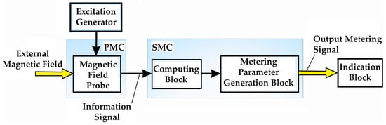
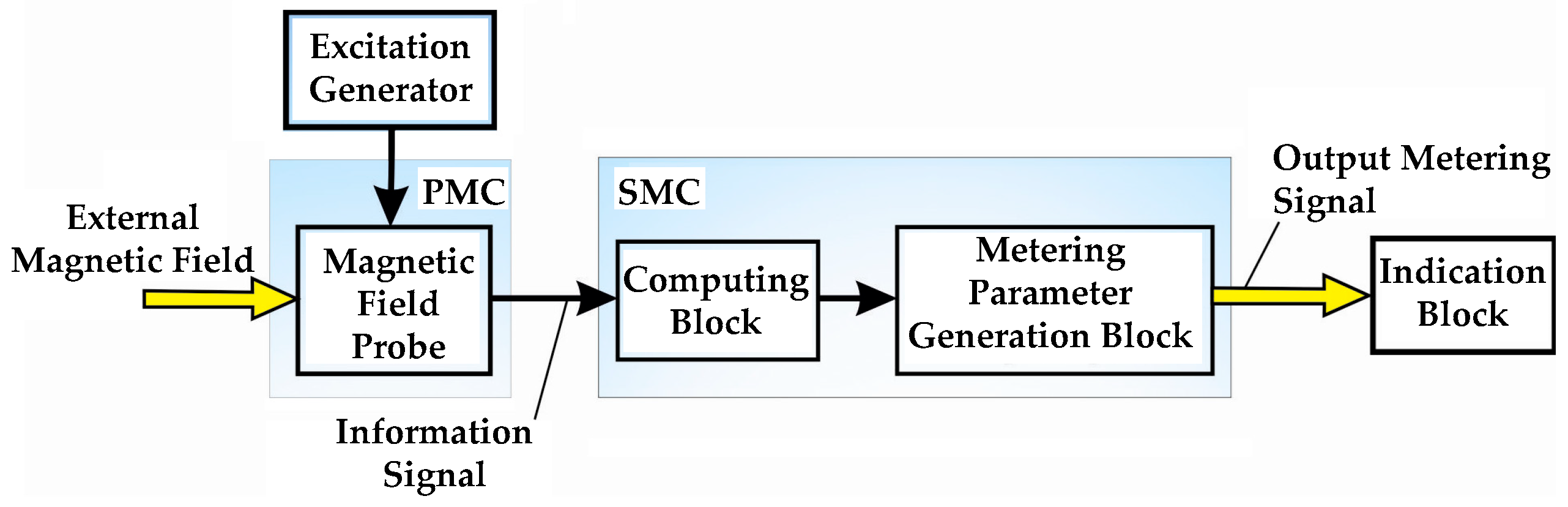
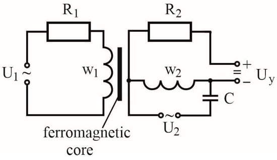
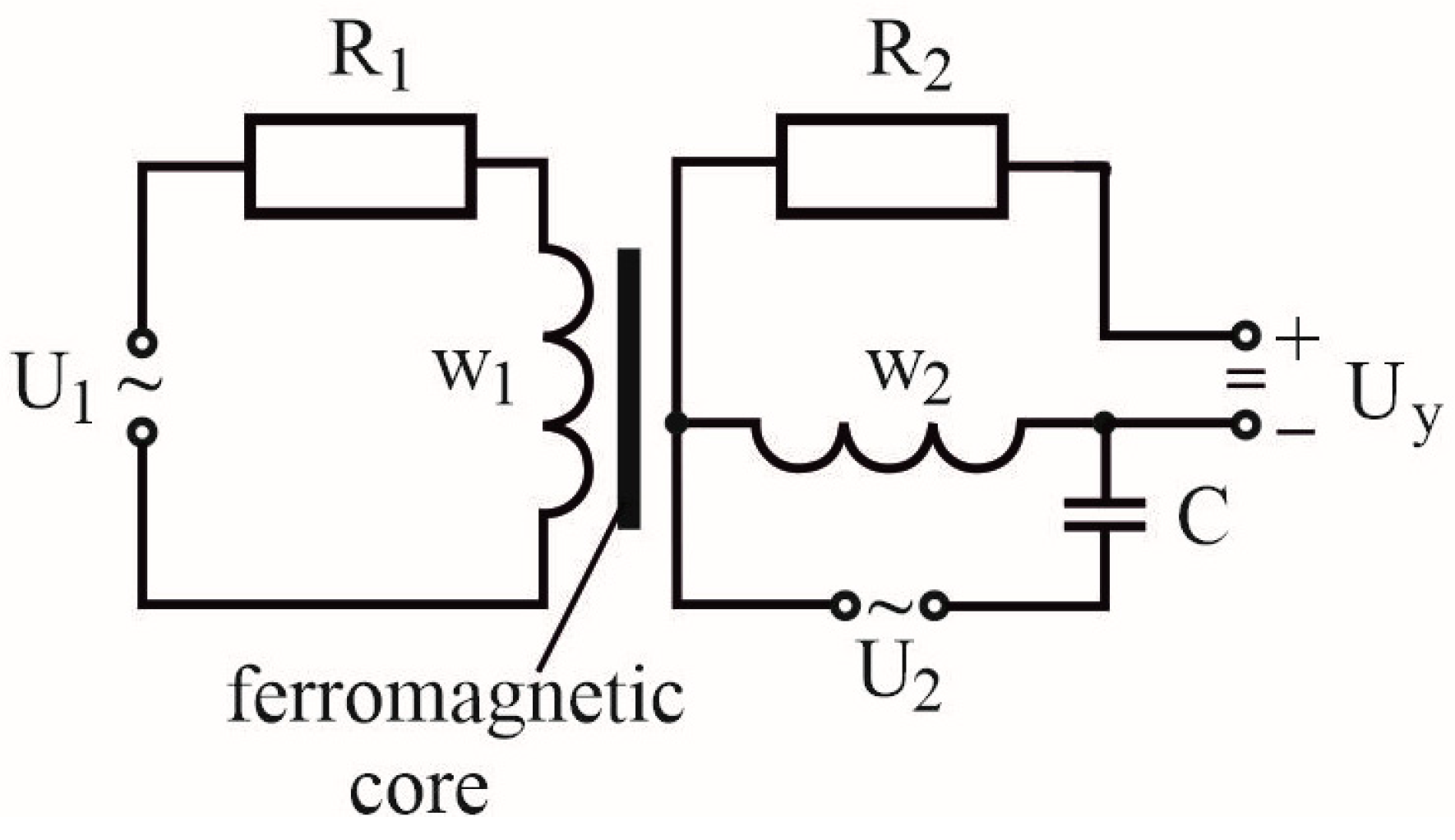
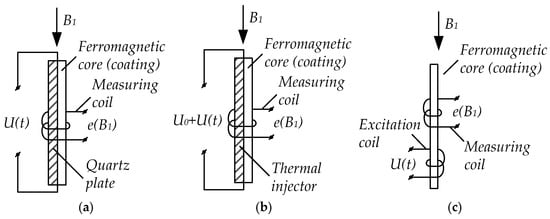
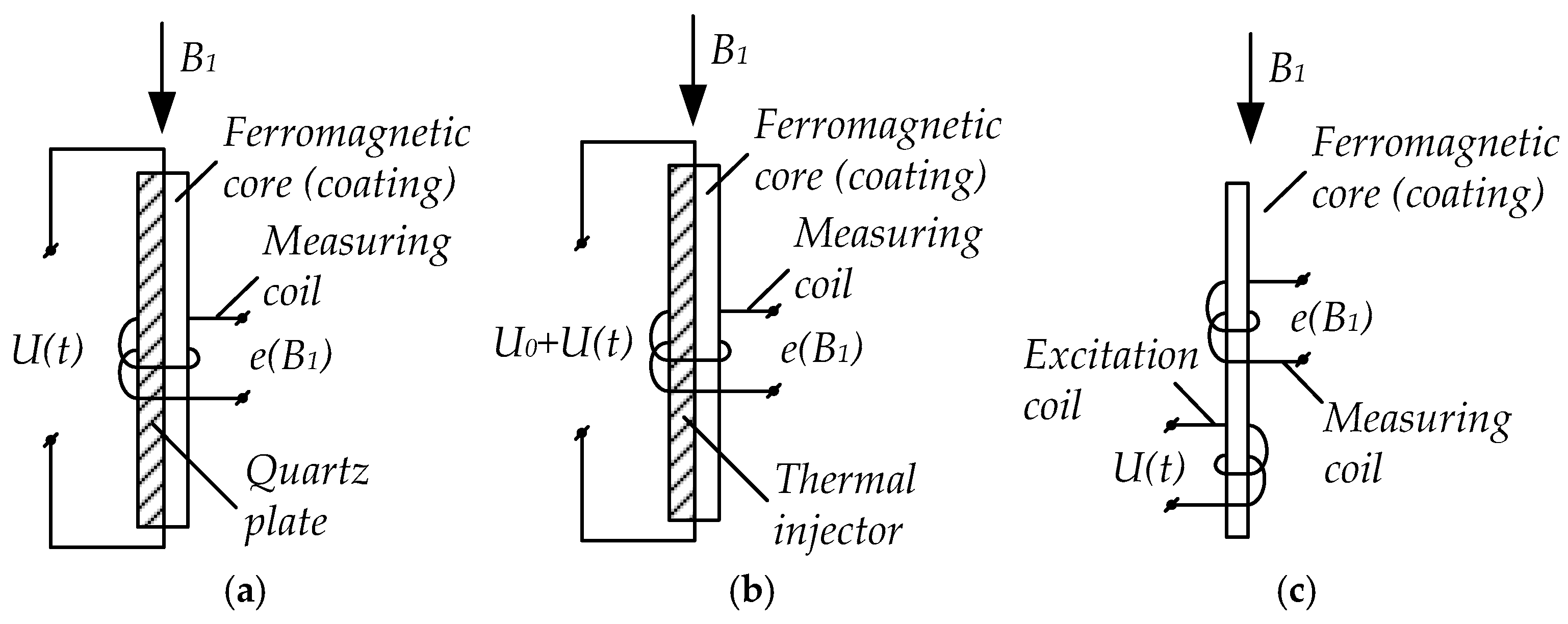
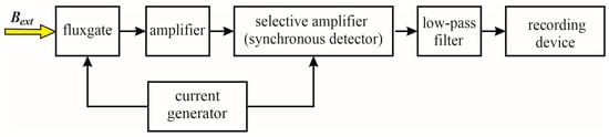
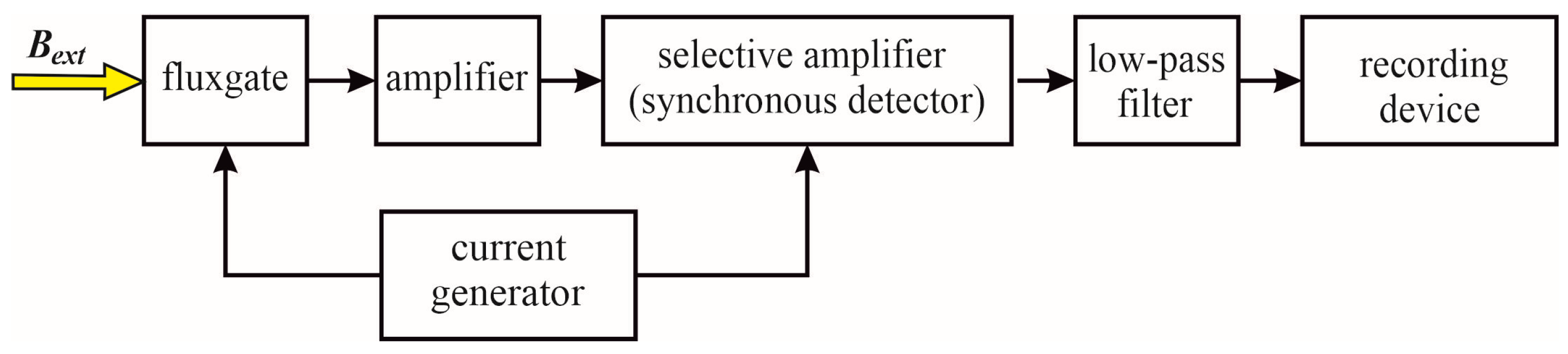
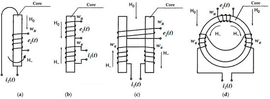
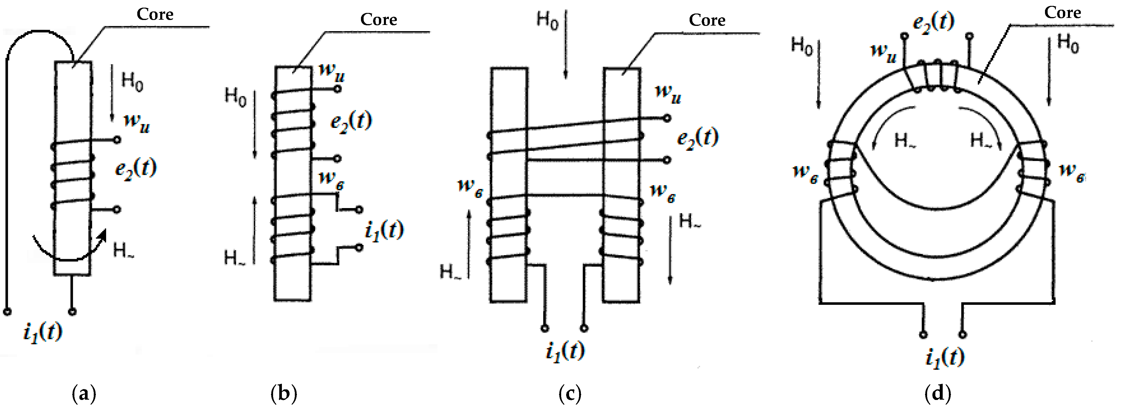
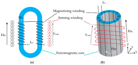

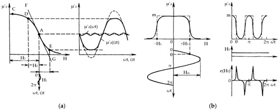
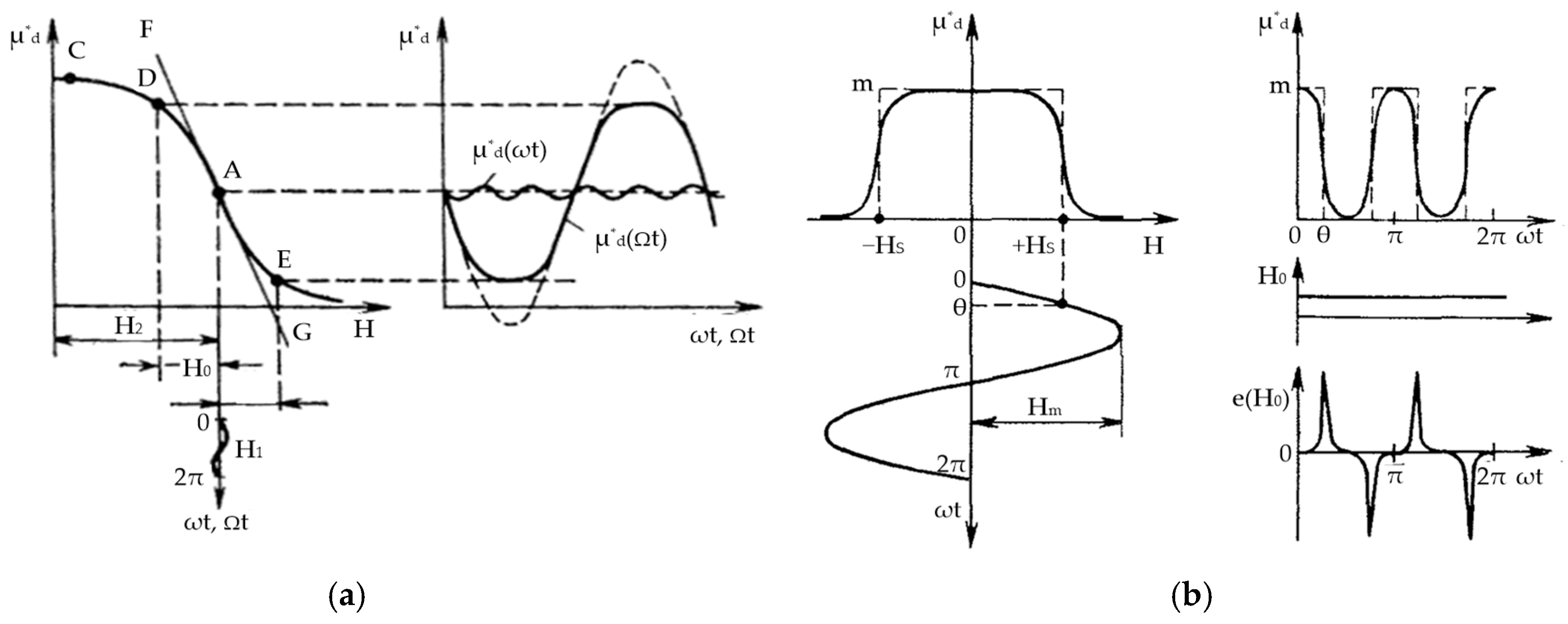
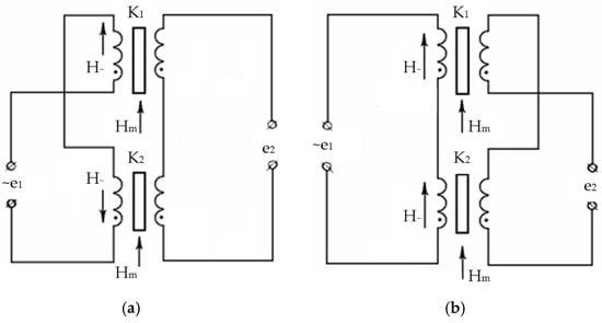
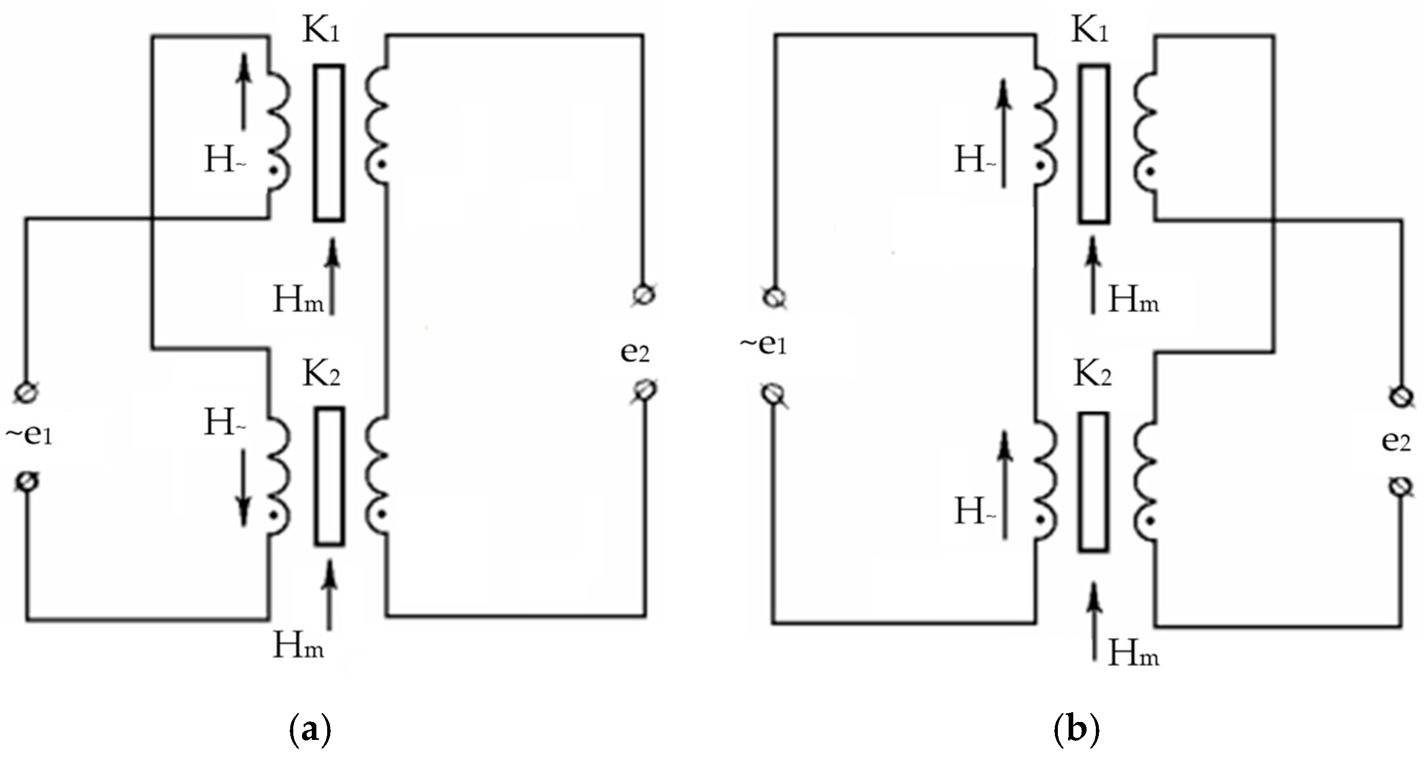
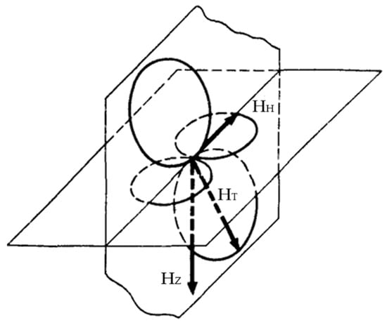
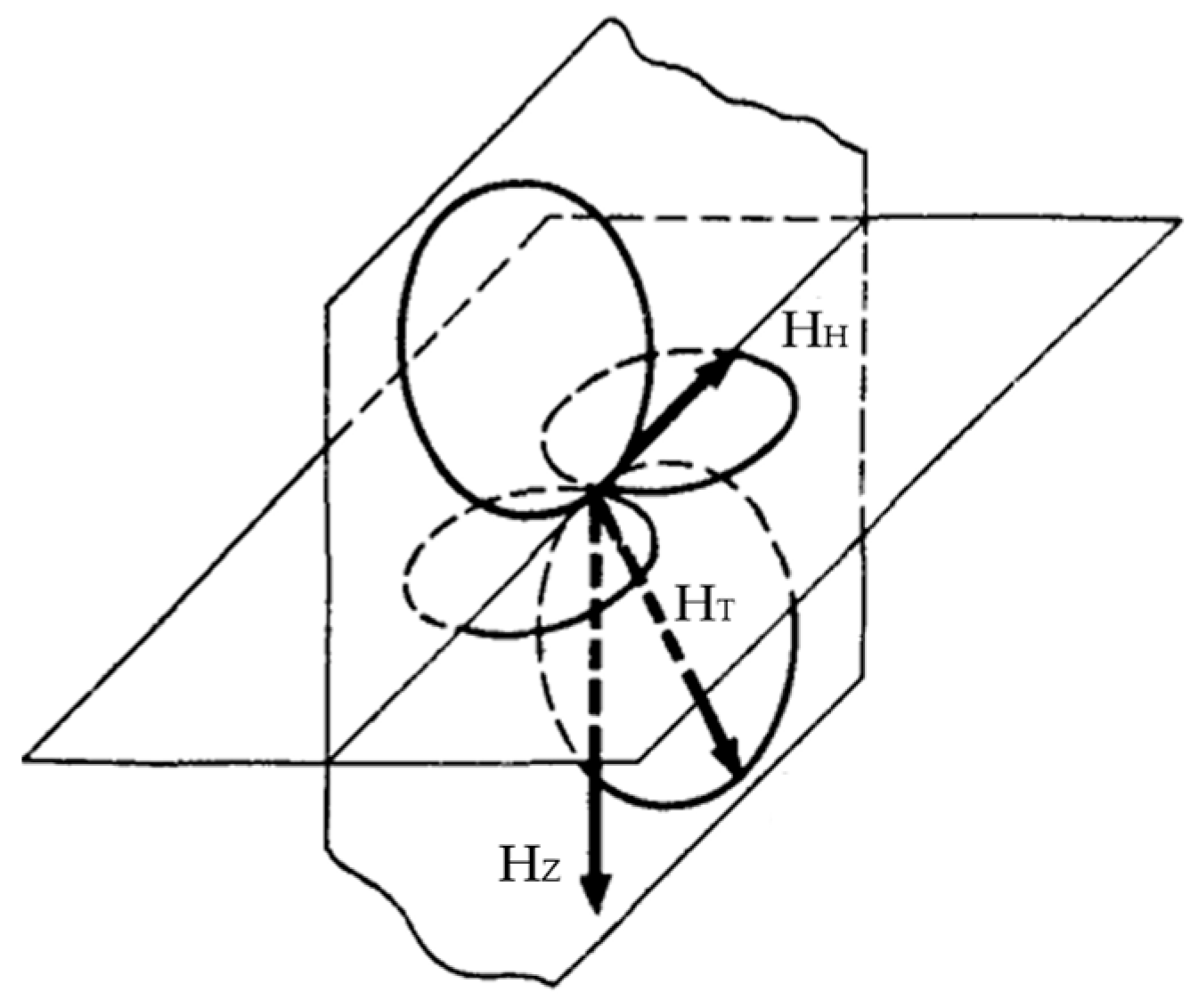
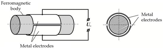
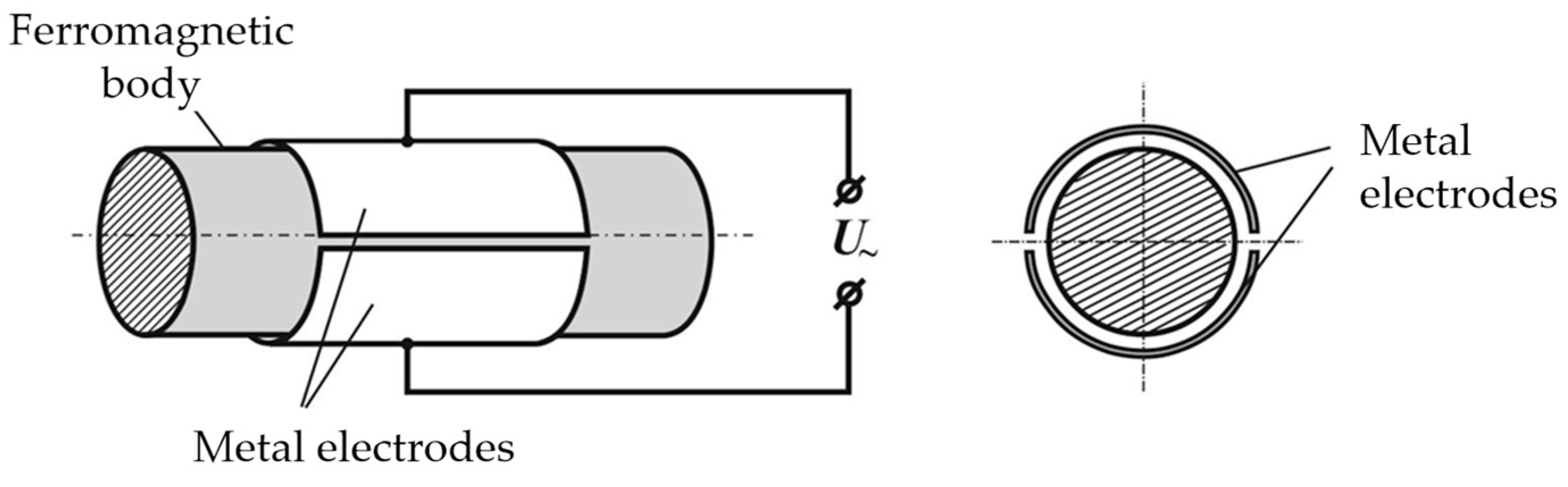
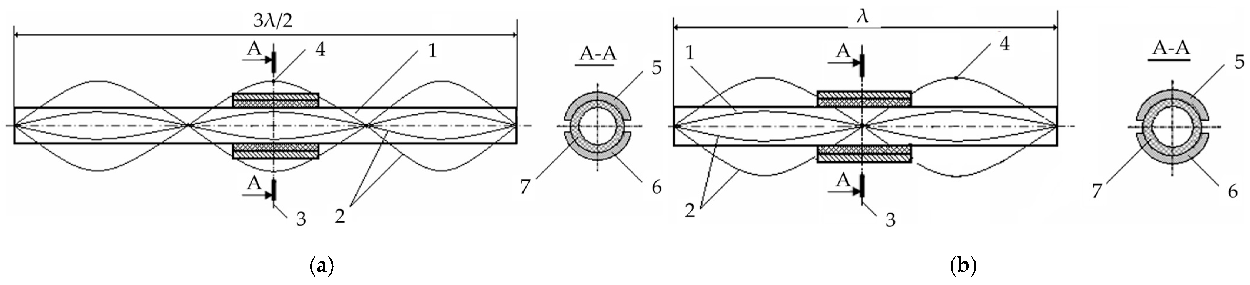
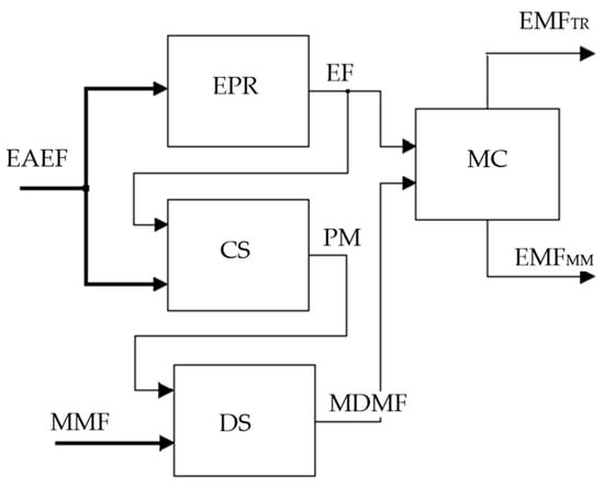
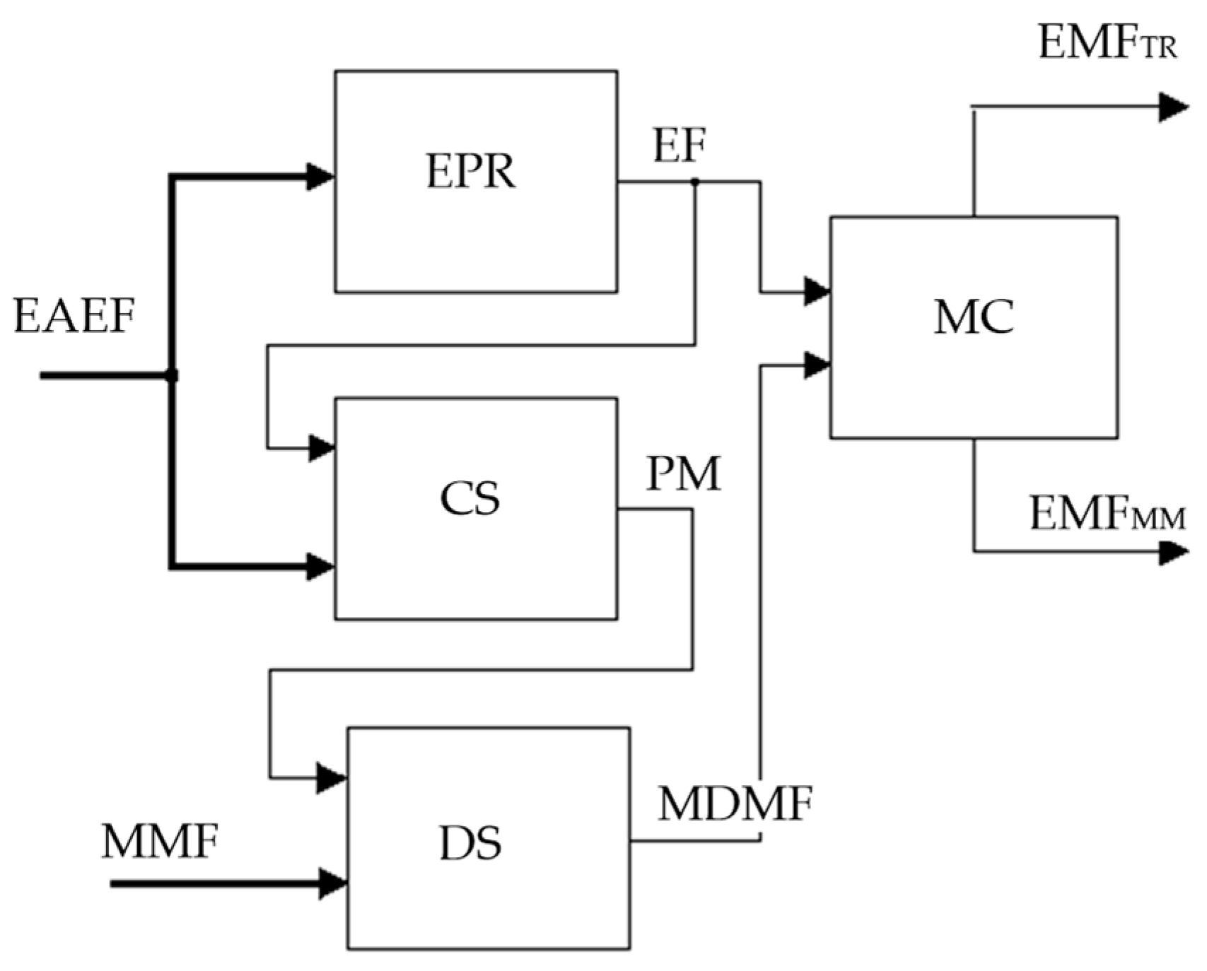
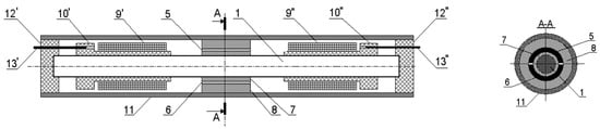
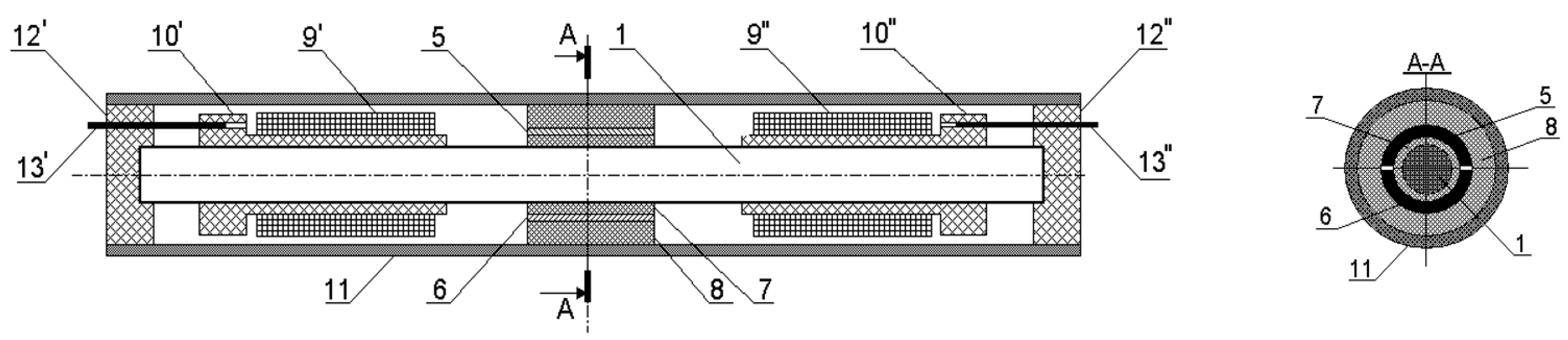
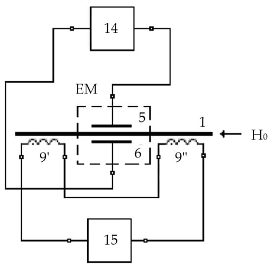
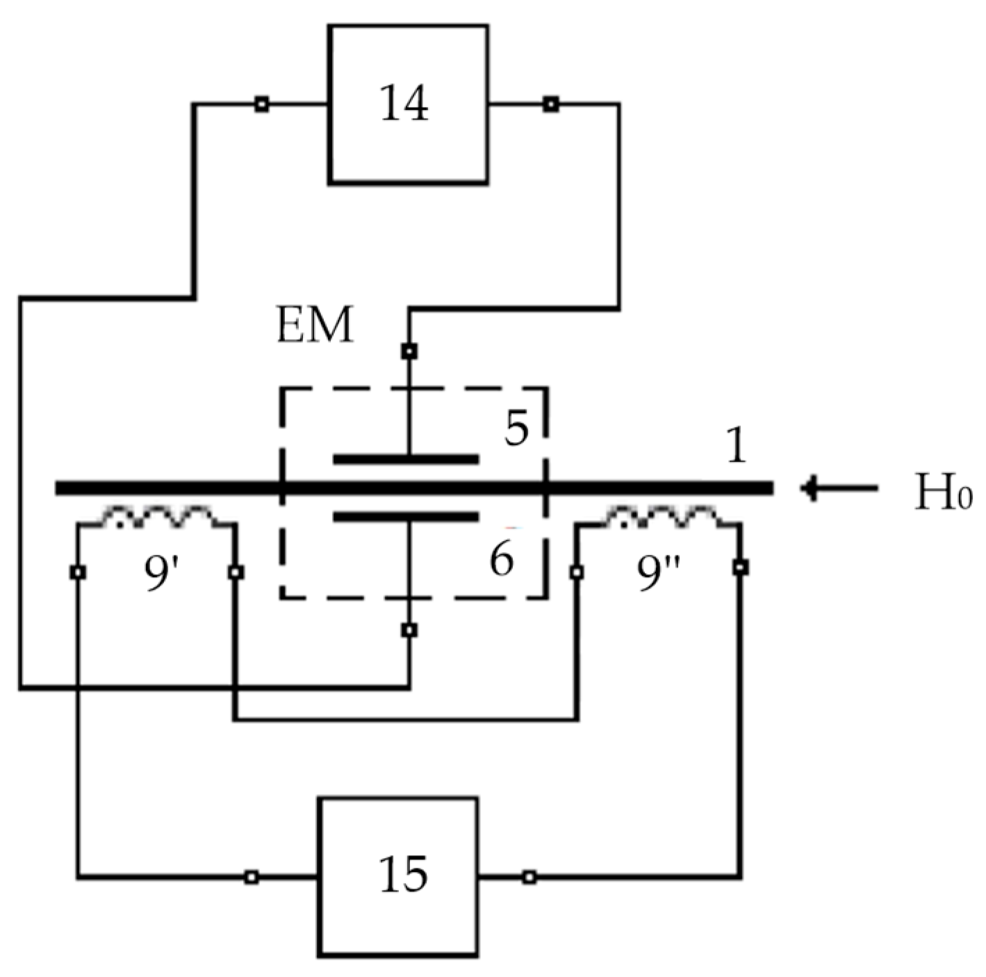
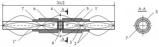
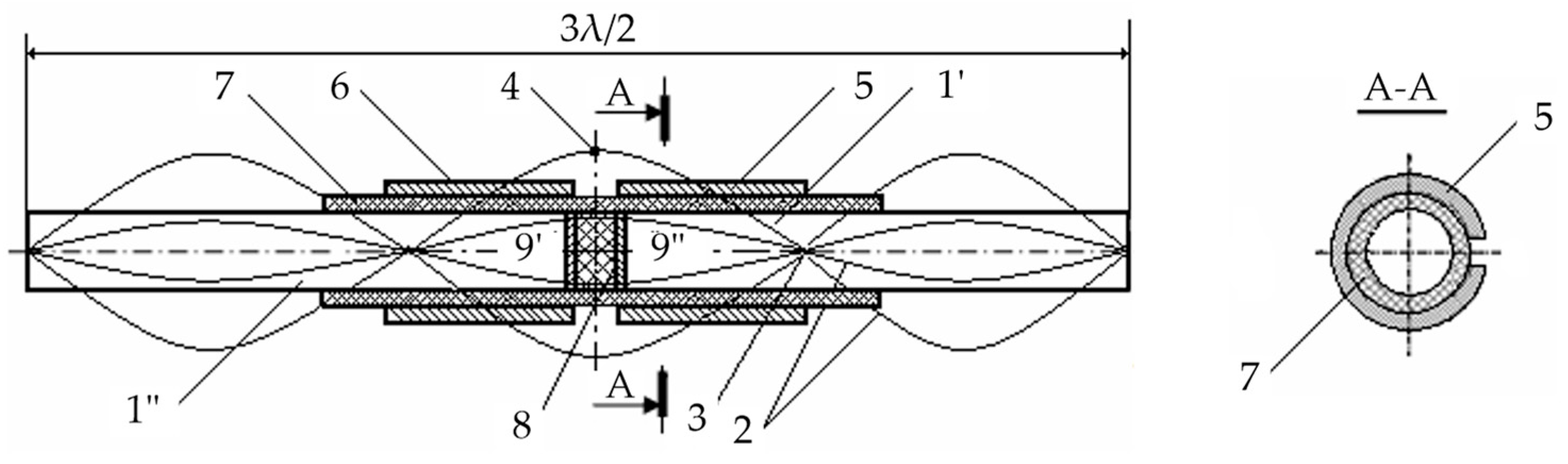
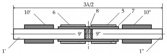
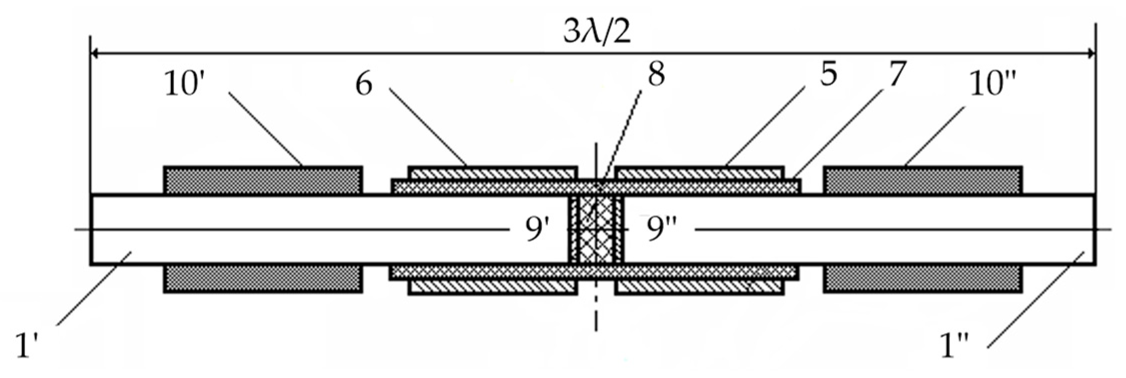
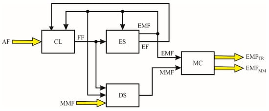
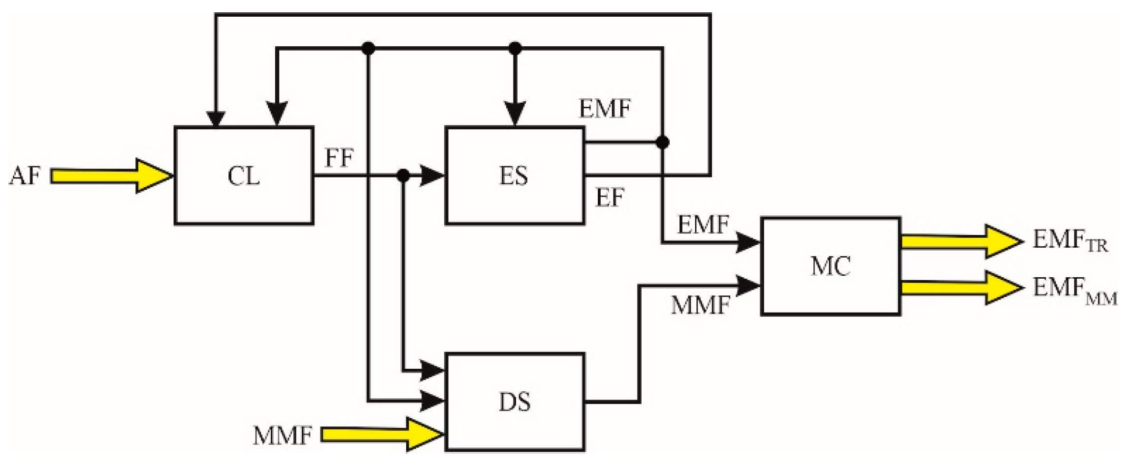
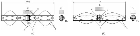
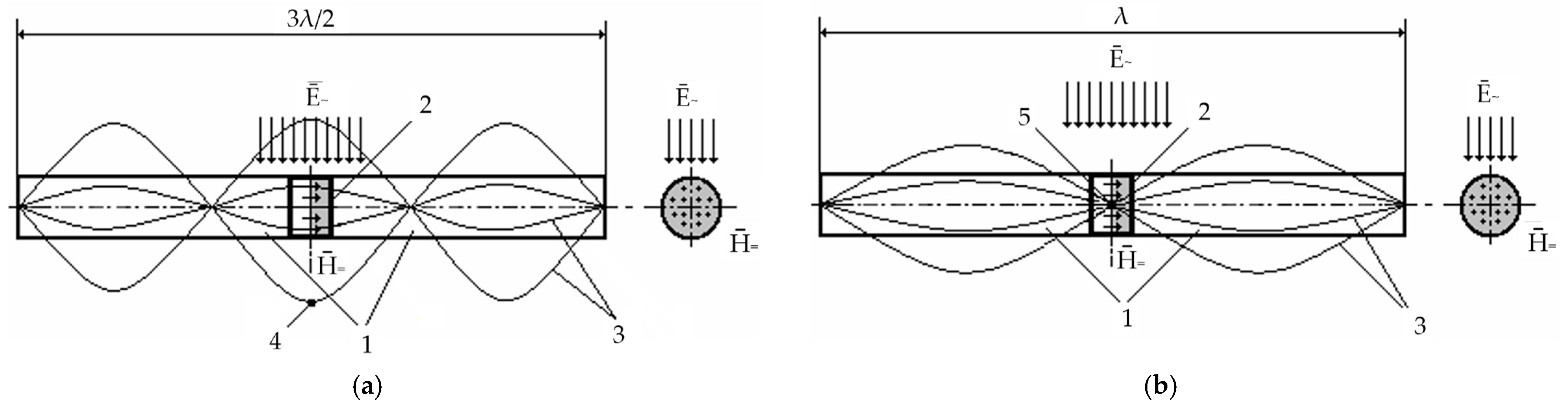
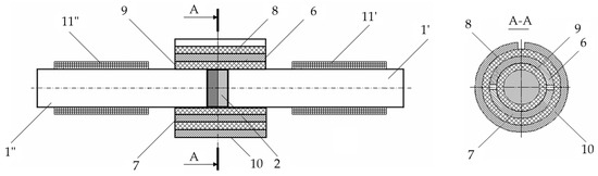
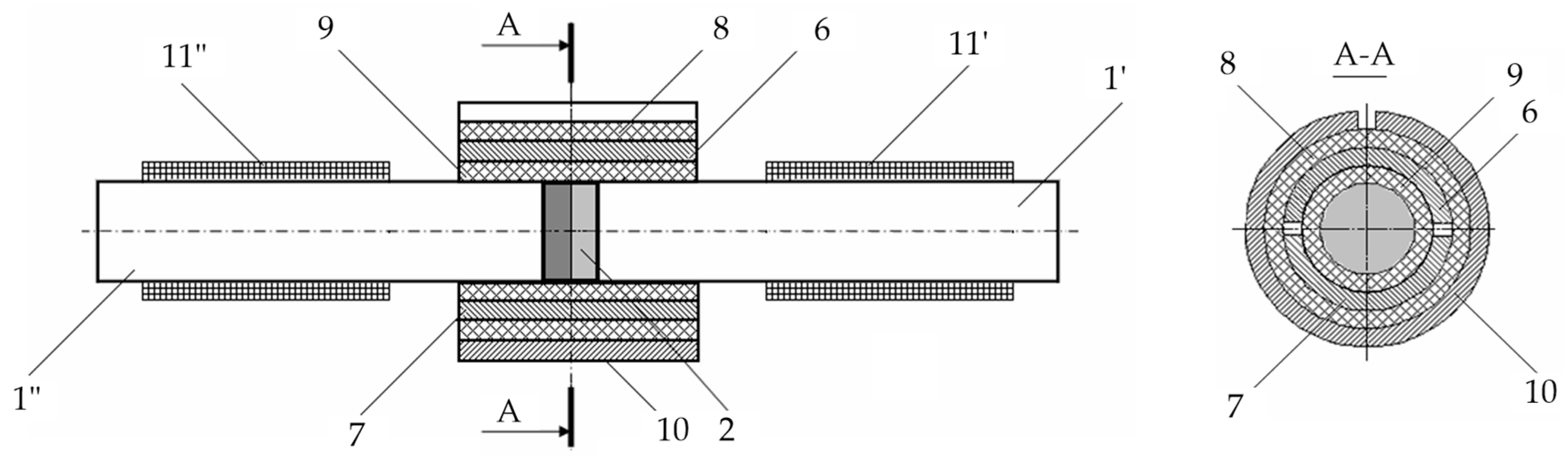
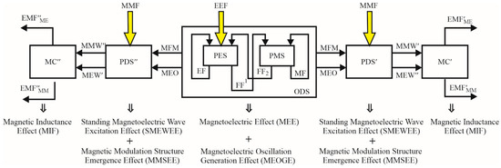
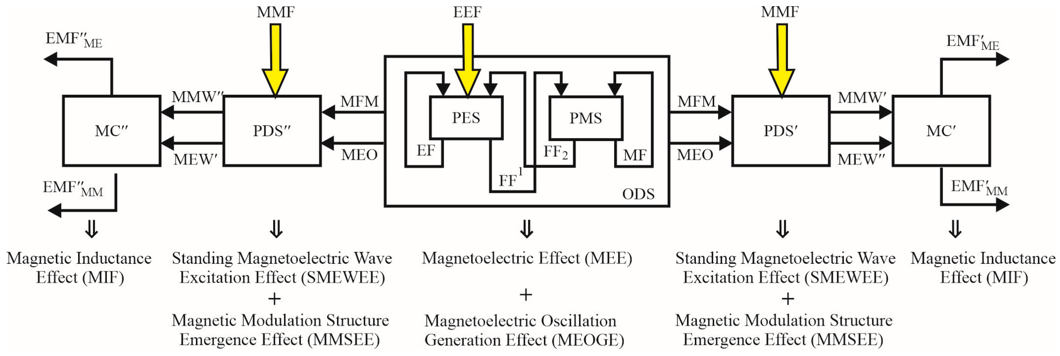
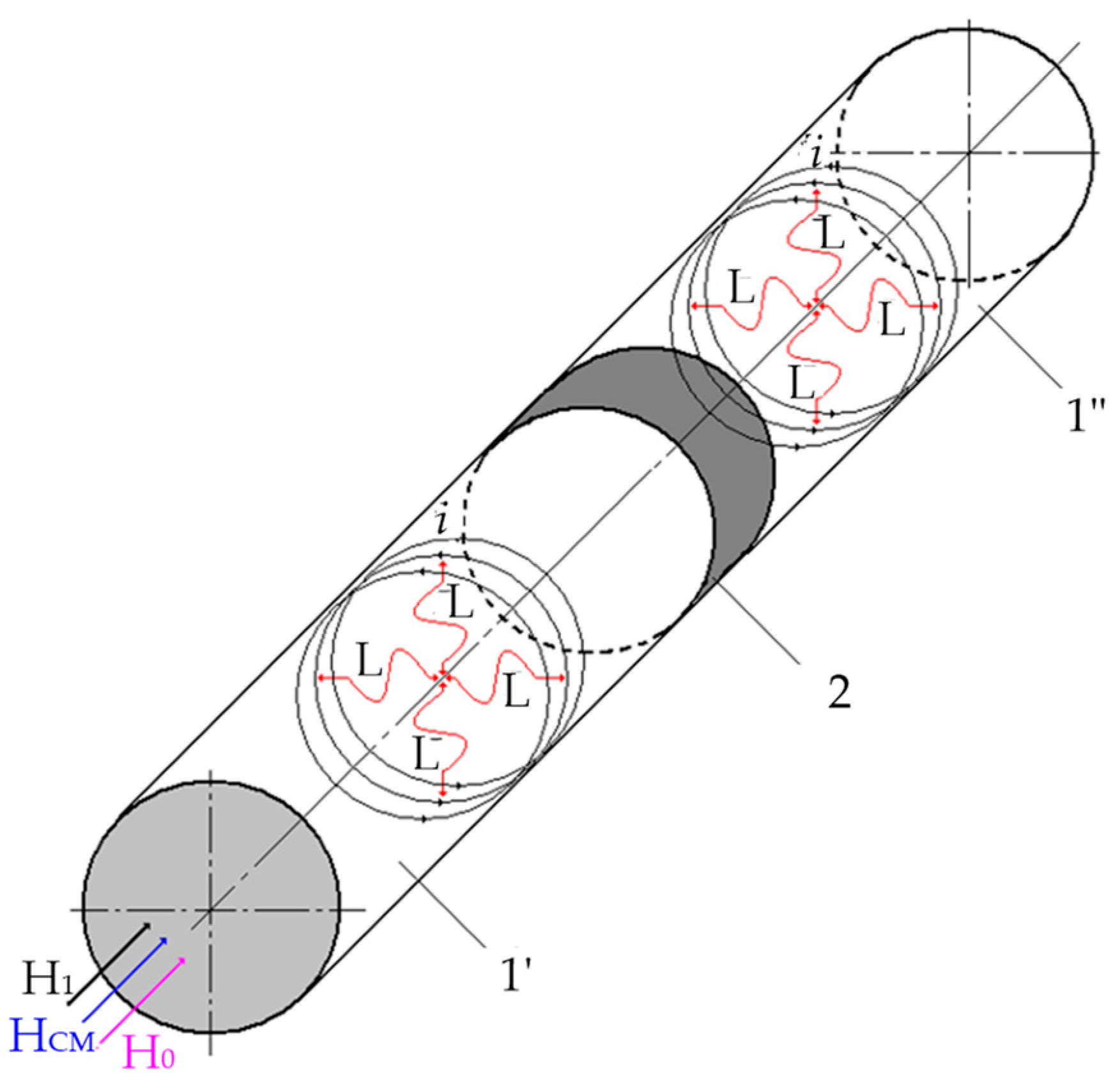
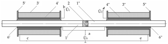
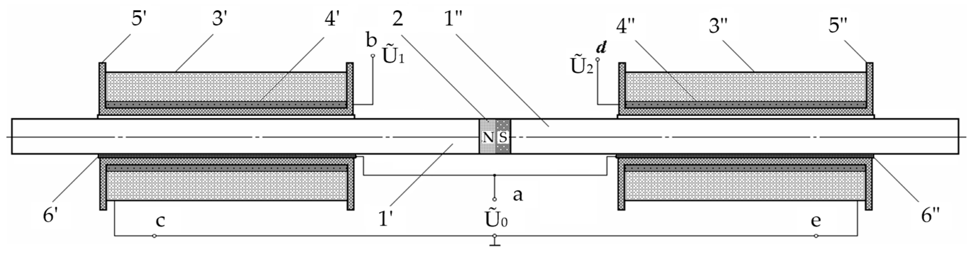
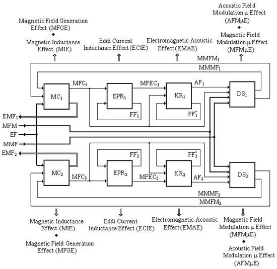
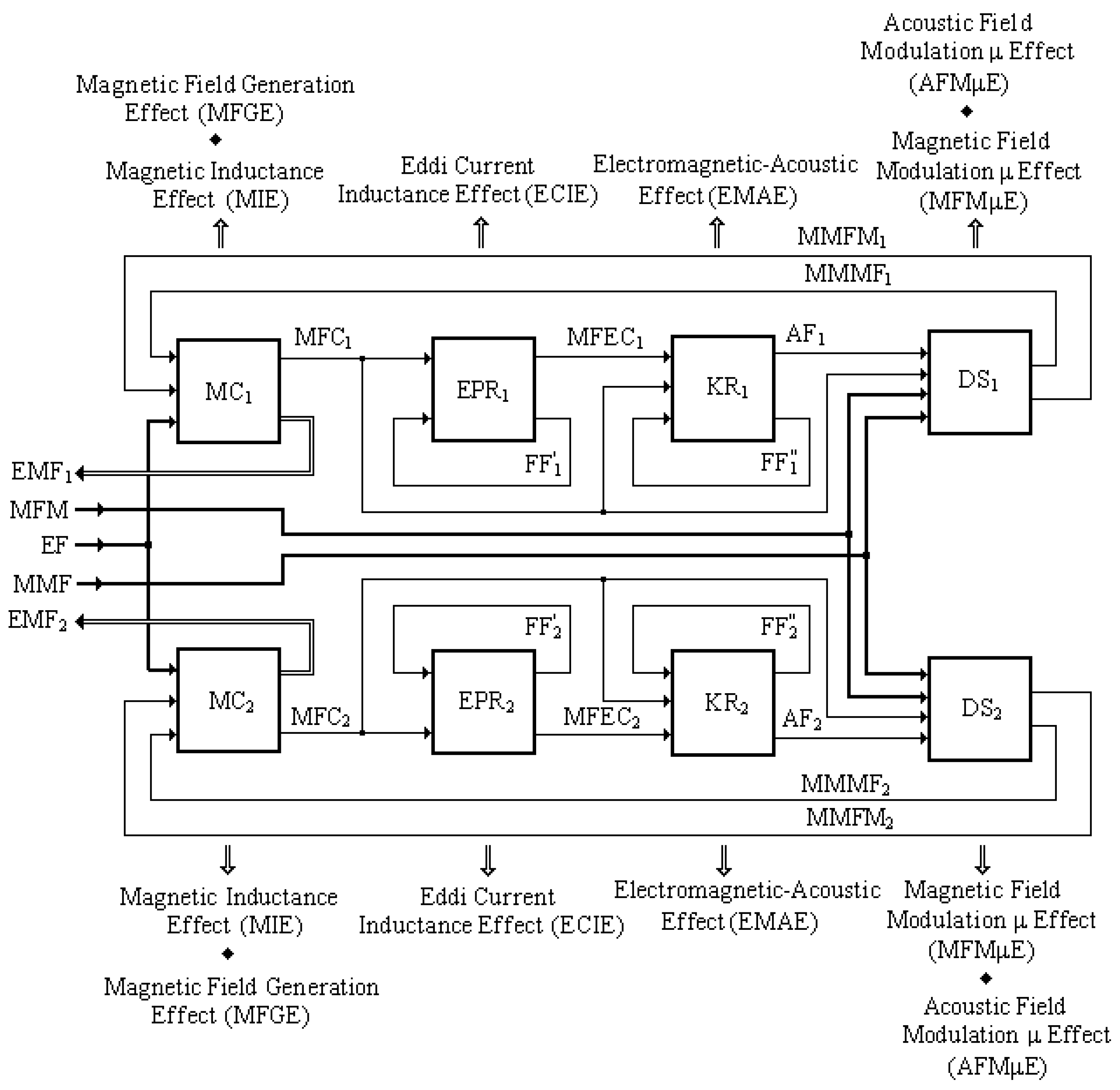
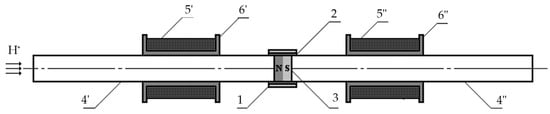
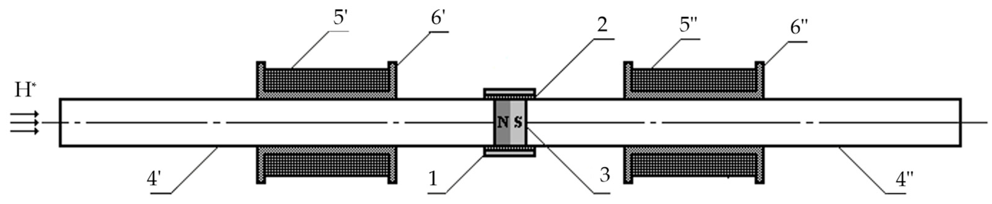
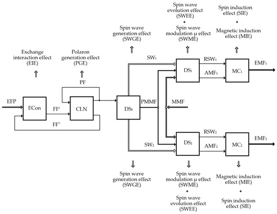
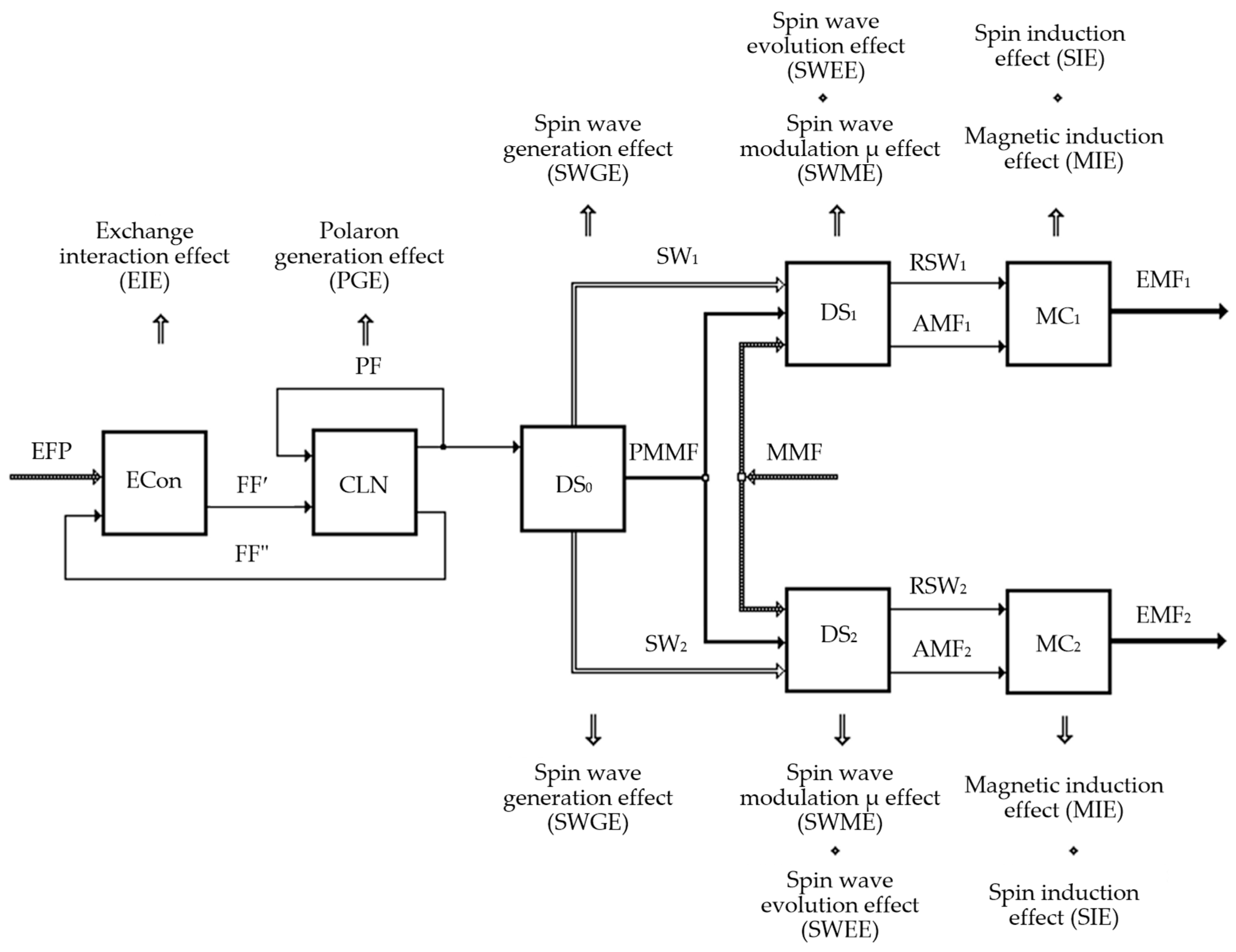

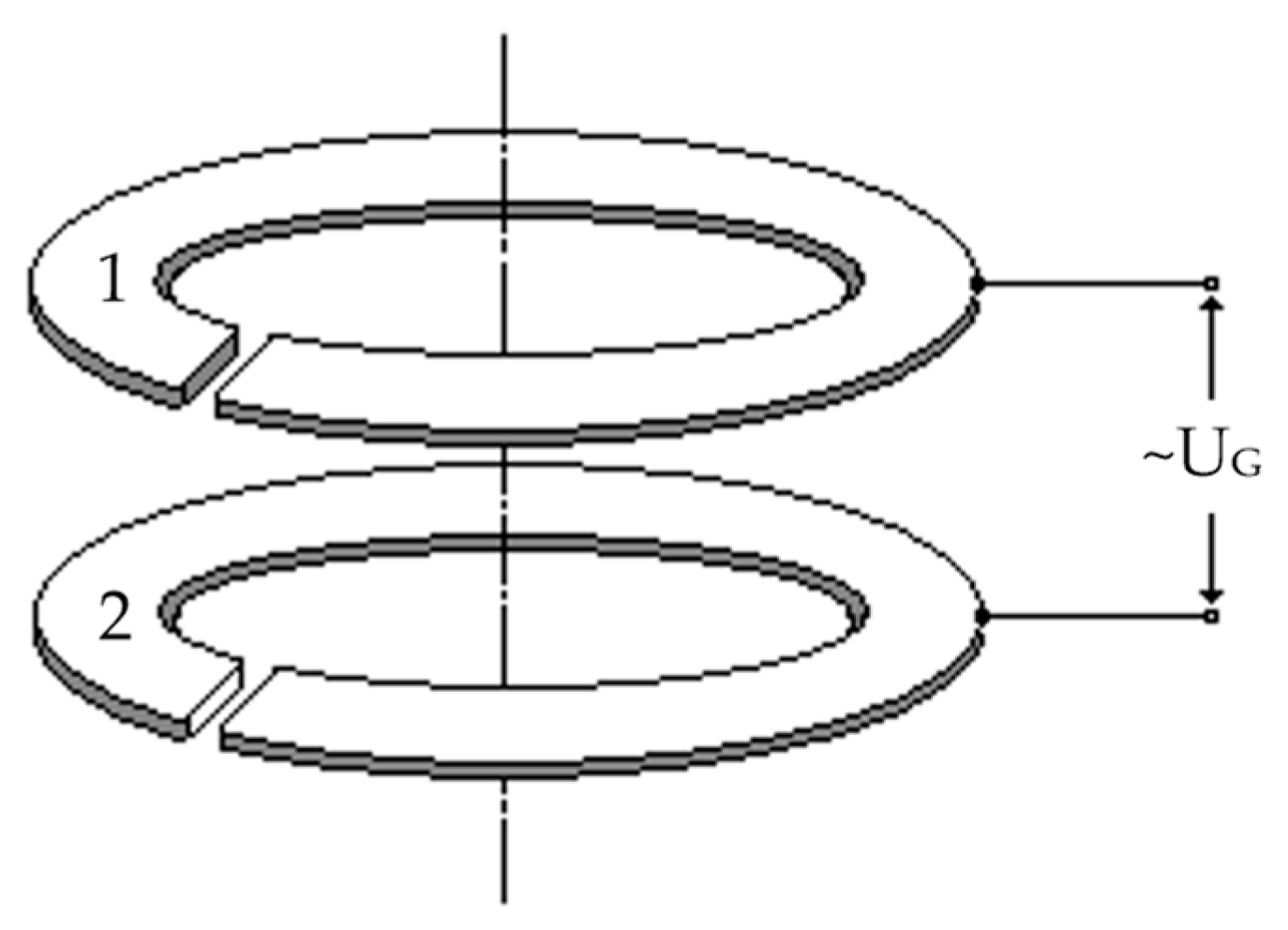
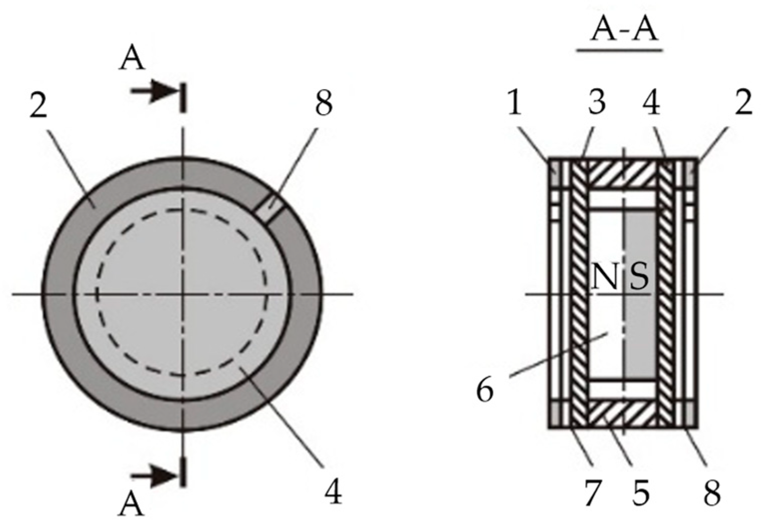
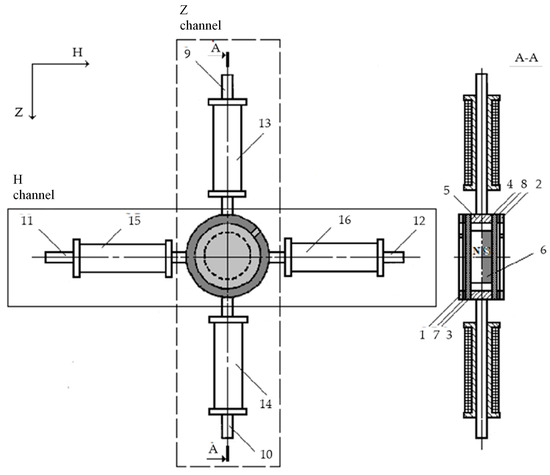
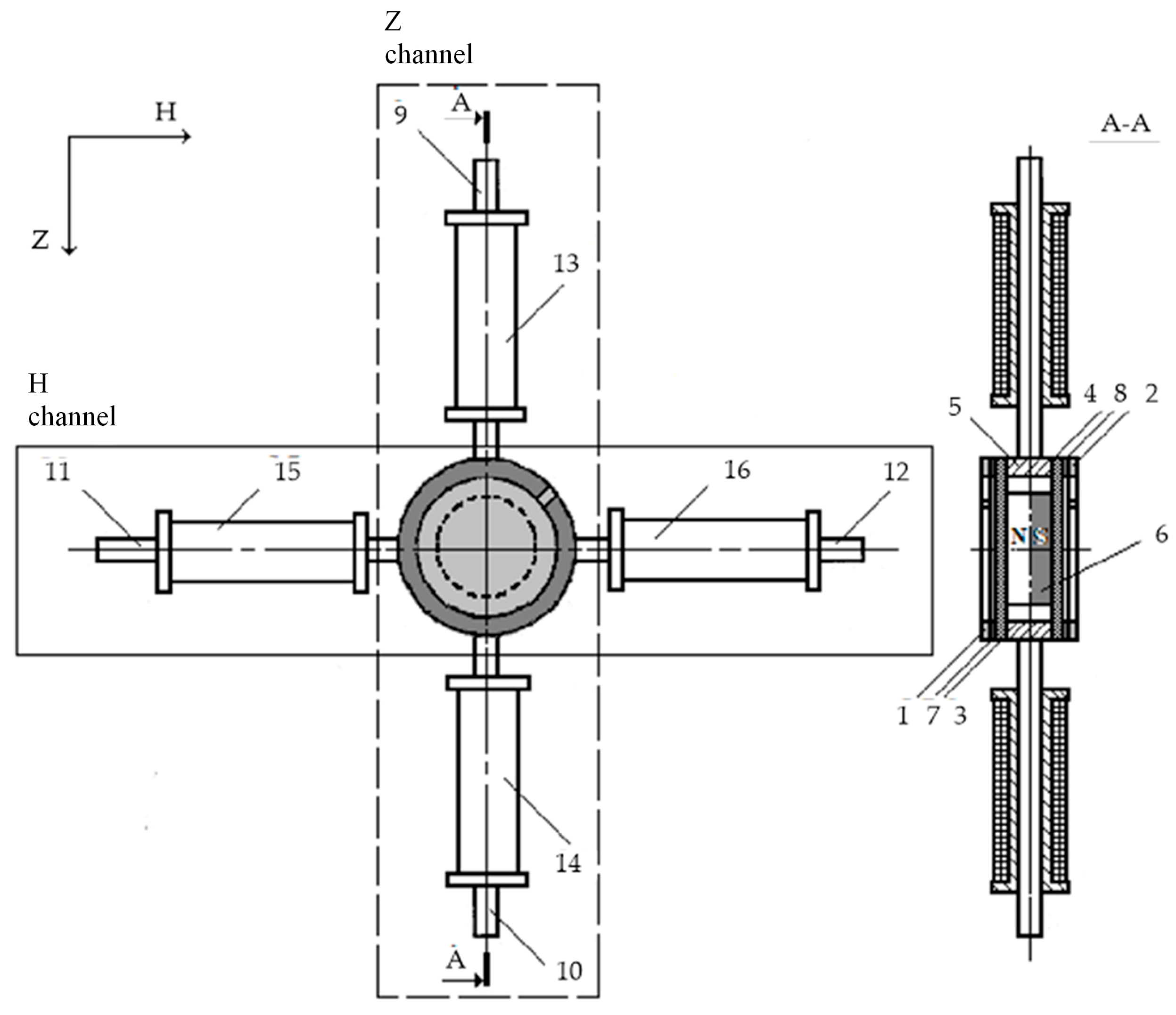
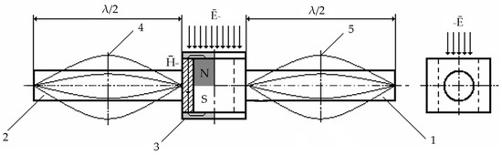
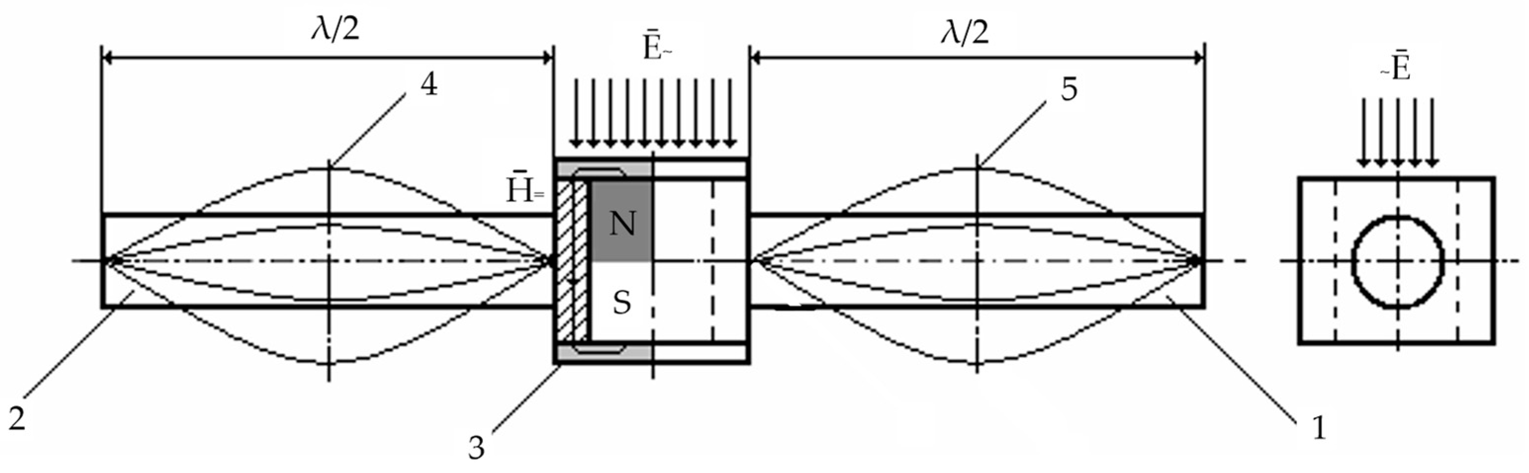
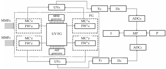
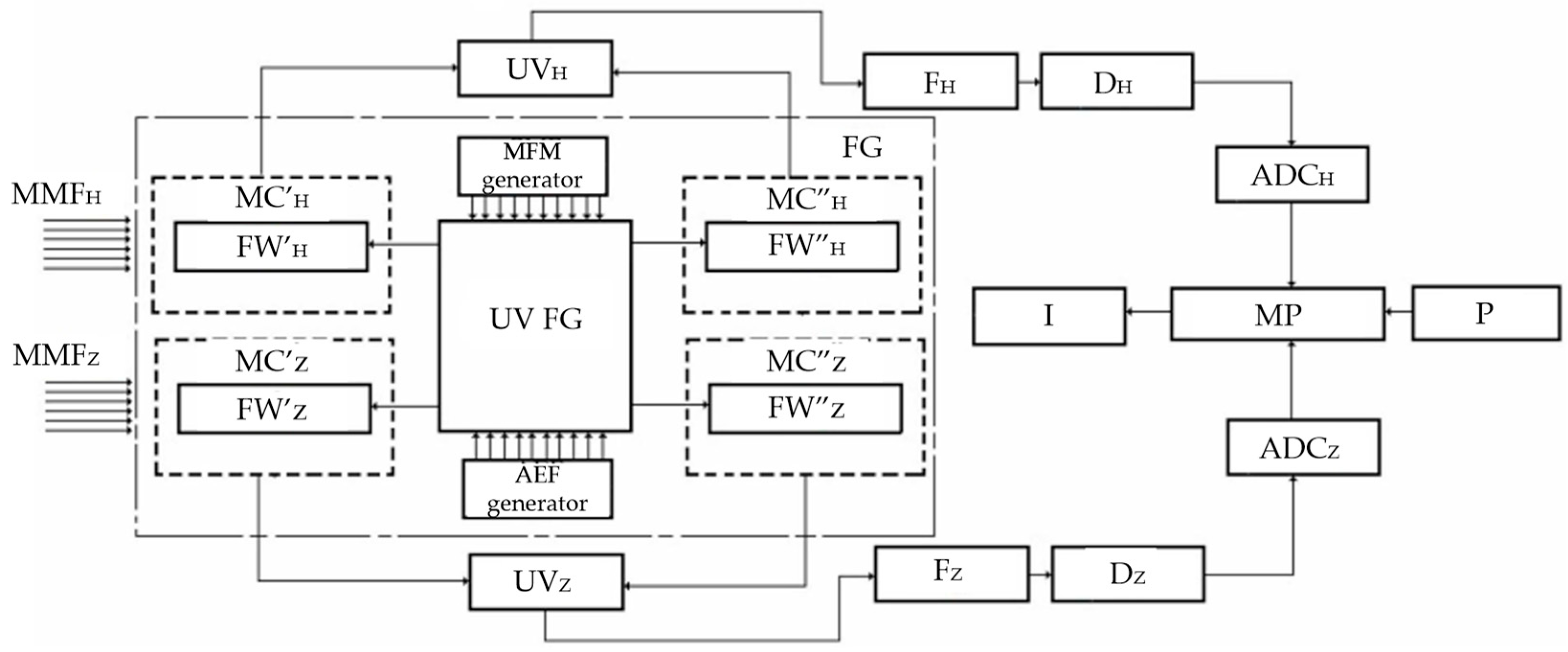

Disclaimer/Publisher’s Note: The statements, opinions and data contained in all publications are solely those of the individual author(s) and contributor(s) and not of MDPI and/or the editor(s). MDPI and/or the editor(s) disclaim responsibility for any injury to people or property resulting from any ideas, methods, instructions or products referred to in the content. |
© 2026 by the authors. Licensee MDPI, Basel, Switzerland. This article is an open access article distributed under the terms and conditions of the Creative Commons Attribution (CC BY) license.