


Abstract
To enable effective regulation of the contact pattern location on tooth flanks and eliminate edge contact in cylindrical helical gear pairs, a novel asymmetric modification method that simultaneously addresses both the tooth profile and the tooth lead direction is proposed. Firstly, a mathematical model of the theoretical tooth flank of cylindrical helical gears is derived. Then, the superposed modification amounts are formulated on the tooth surface by dividing into subregions along the profile and width directions, and the mathematical model of asymmetrically modified cylindrical helical gear tooth flanks is established by integrating the theoretical tooth surface and the superposed modification amounts. Finally, the finite element analysis meshing models with unmodified, symmetrical, and asymmetric modified tooth flanks are established to verify the feasibility of this method through comparative contact pattern location. The result shows that tooth surface asymmetric modification retains the ability to eliminate edge contact and an additional capability of regulating the contact pattern location is achieved, which is more adaptable to diverse application scenarios in gear transmission systems.
1. Introduction
Cylindrical gears are among the most widely used gear types and serve as core components in mechanical transmission systems across industrial equipment. They are extensively employed in aerospace engineering, marine power systems, and automotive powertrains. Tooth flank modification represents one of the critical approaches to improving performance by eliminating edge contact and counteracting the influence of installation deviations, thereby enhancing meshing quality and service life. Nevertheless, existing tooth surface modification strategies are predominantly based on symmetrical approaches. While they are effective in eliminating edge contact, they offer limited compensation for installation deviations and result in a significant loss of contact pattern area. Therefore, it is necessary to investigate asymmetric tooth flank modification to enhance the efficiency of gear tooth surface design optimization.
Tooth flank modification, as one of the important methods for improving the meshing performance of gear pairs, has been studied by many scholars. Liu et al. [1] proposed a cylindrical gear modification method based on a mapping relationship, where the tooth flank was divided into different regions with a superposed profile and lead modification amounts to achieve symmetric modification. Niemann et al. [2] systematically presented the theoretical framework of gear tooth flank modification, where the profile and lead modification amounts were determined based on load, manufacturing deviations, and mesh stiffness. Fetvaci et al. [3] developed a mathematical model for the generation simulation of conical involute gears with asymmetric involute tooth profiles manufactured by rack-type cutters. Jia et al. [4] developed a novel compensation–conjugation-based method to reduce the peak-to-peak transmission error (PPTE) in cylindrical gear modification and presented procedures for establishing a mathematical model of modified tooth flanks. Autiero et al. [5] established an analytical mesh stiffness model for spur gears, highlighting the influence of profile modification on the harmonic components of gear mesh stiffness and the dynamic behavior of systems under varying loads. Zhang et al. [6] adopted a bidirectional composite modification method combining lead and profile modifications, constructed a composite modification model for cylindrical gears considering installation errors, and further analyzed the meshing performance under axial displacement and angular misalignment conditions. Liu et al. [7] proposed a tooth flank modification design method based on parabolic forming blades and tool inclination angles, derived the modified tooth flank equation, and analyzed the influence of modification parameters on tooth flank curvature characteristics. Zhao et al. [8] established a tooth contact model for cylindrical gears with high-order topological modification and misalignment and investigated the effects of errors and different modification curve combinations on tooth contact patterns and transmission error. Sanchez et al. [9] proposed a simplified analytical model for mesh stiffness, load sharing, and transmission error of profile-shifted spur gears considering surface wear and explored the optimal profile modification to minimize dynamic loads induced by transmission error. Gao et al. [10] presented a dynamic optimization modification technique for involute spur gears, analyzed the variation trend of dynamic characteristics after dynamic modification, and verified the vibration reduction effect of dynamic optimization modification in fixed-axis gear transmission systems. Ghosh et al. [11] derived optimal profile corrections for tooth profile and pitch errors using semi-analytical and graphical methods under various operating conditions. Pedrero et al. [12] investigated the optimal tip modification to minimize the peak-to-peak amplitude of transmission error considering wear. Ma et al. [13] established a controllable design model and a tooth flank optimization model to compute the optimal modification parameters. Sun et al. [14] proposed a comprehensive modification method for traction arc tooth cylindrical gears. Dias et al. [15] studied the influence of profile modification on the meshing vibration of spur gears. Rana et al. [16] developed a mathematical model for twist-free lead crowning of spur gears via pulsed electrochemical flank modification and validated it experimentally. Abruzzo et al. [17] proposed a novel iterative algorithm for designing spur gear profile modifications based on minimizing the peak-to-peak static transmission error to improve dynamic behavior. Pedrero et al. [18] analyzed the tip interference phenomenon in low gear ratio internal spur gears with profile modification and derived the relevant design constraints. Zou et al. [19] established a dynamic model of a spur gear pair that couples angular misalignment fault and tooth modification to predict the dynamic response of the system. Zhao et al. [20] investigated the meshing characteristics of spur gear pairs with tooth modification under different assembly errors and conducted a sensitivity analysis of the impact factors. Rana et al. [21] improved the functional performance characteristics of spur gears through flank modifications produced by a non-contact advanced finishing process. Li et al. [22] proposed a novel method for longitudinal modification of non-circular cylindrical gears and carried out the corresponding tooth contact analysis. Abruzzo et al. [23] presented a dynamic model for spur gears with profile modification that combines the average and local meshing stiffnesses based on the static transmission error. Zhou et al. [24] proposed a new dynamics modeling method for a spur gear pair with tooth profile modification, namely the equivalent static error method. While substantial efforts have been devoted to the formation mechanism of cylindrical gears, modification methodologies, and meshing performance of modified tooth flanks, the existing modification approaches are predominantly based on symmetric modification schemes. Such symmetric methods inevitably sacrifice a certain portion of the contact pattern area because the modification curves must remain symmetric, and they lack the flexibility to effectively regulate the contact pattern location under complex operating conditions. Consequently, they can no longer fully satisfy the practical demands of meshing analysis and engineering applications of cylindrical gear tooth flanks.
To address this gap, this paper proposes an asymmetric tooth flank modification method on the basis of previous studies. Firstly, a mathematical model of the theoretical tooth flank of cylindrical helical gears is derived. Then, the superposed modification amounts are formulated on the tooth surface by dividing into subregions along the profile and width directions. And the mathematical model of asymmetrically modified cylindrical helical gear tooth flanks is established by integrating the theoretical tooth surface and the superposed modification amounts. Finally, the finite element analysis meshing models with unmodified, symmetrical, and asymmetric modified tooth flanks are established to verify the feasibility of this method through comparative contact pattern location and contact pattern area.
2. Theoretical Mathematical Model of Cylindrical Helical Gear
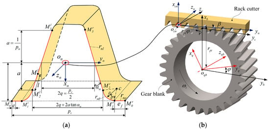
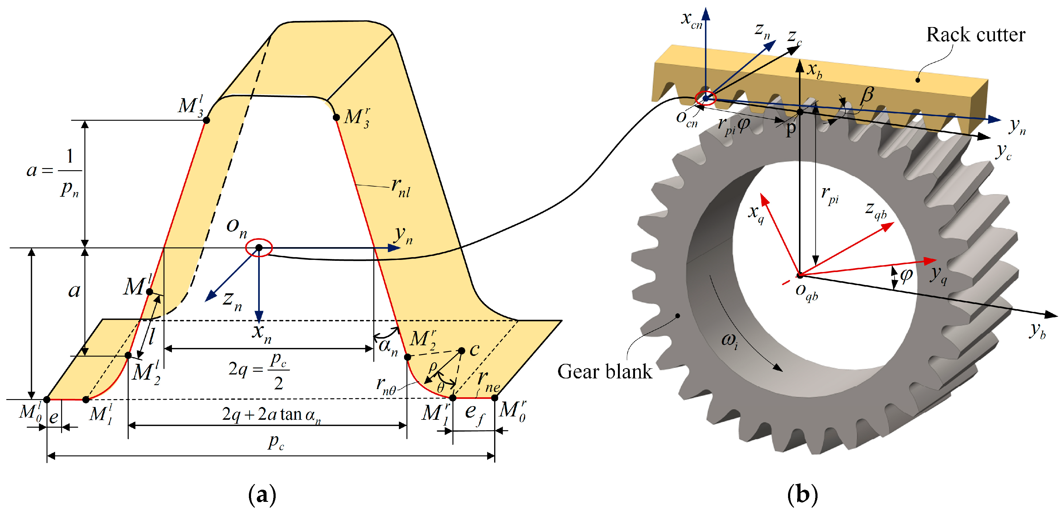
Figure 1 illustrates the generation process of cylindrical helical gears. The cylindrical helical gear is generated by cutting the gear blank with the rack cutter. The normal section of the rack cutter in the coordinate system is illustrated. The rack cutter consists of left and right cutting edges, and each cutting edge is composed of three sections, namely straight segments , circular arc segments , and additional straight segments , which generate the dedendum, fillet, and working tooth flank, respectively. The right superscript i is r and l represent the right and left cutting edges, respectively. The expression of the three sections of cutter edge in the coordinate system can be represented as . The symbol X represents the variables e, , and , and they respectively represent the tooth root straight segments, circular arc segments, and additional straight segments. represents the pressure angle of the rack cutter tooth profile, is the normal pitch of the gear, and stands for the circular pitch of the gear, respectively.
Figure 1.
Generation process of cylindrical gears: (a) normal section of the rack cutter; (b) coordinate transformation.
Moreover, the coordinates of any point on the generated cylindrical gear tooth flank within the coordinate system can be obtained by the following coordinate transformation. The expression of theoretical tooth surface is as follows:
where , , and are the coordinate transformation matrix from to . The parameters , , and are the spiral angle, pitch circle radius, and rotation angle of the gear blank, respectively. includes the tooth root, fillet, and tooth profile section of a single tooth surface.
The meshing equation is employed to solve the tooth surface for the Equation (1), and the meshing equation can be expressed as follows:
where is the normal vectors of the three sections for the tooth surface and is the relative velocity in coordinate system of the tooth surface. For a detailed derivation and solution procedure of the meshing equation, readers are referred to Refs. [1,2,3].
3. Mathematical Model of Cylindrical Helical Gears with Ideal Composite Asymmetric Tooth Flank Modification
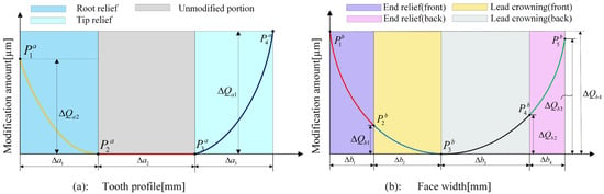
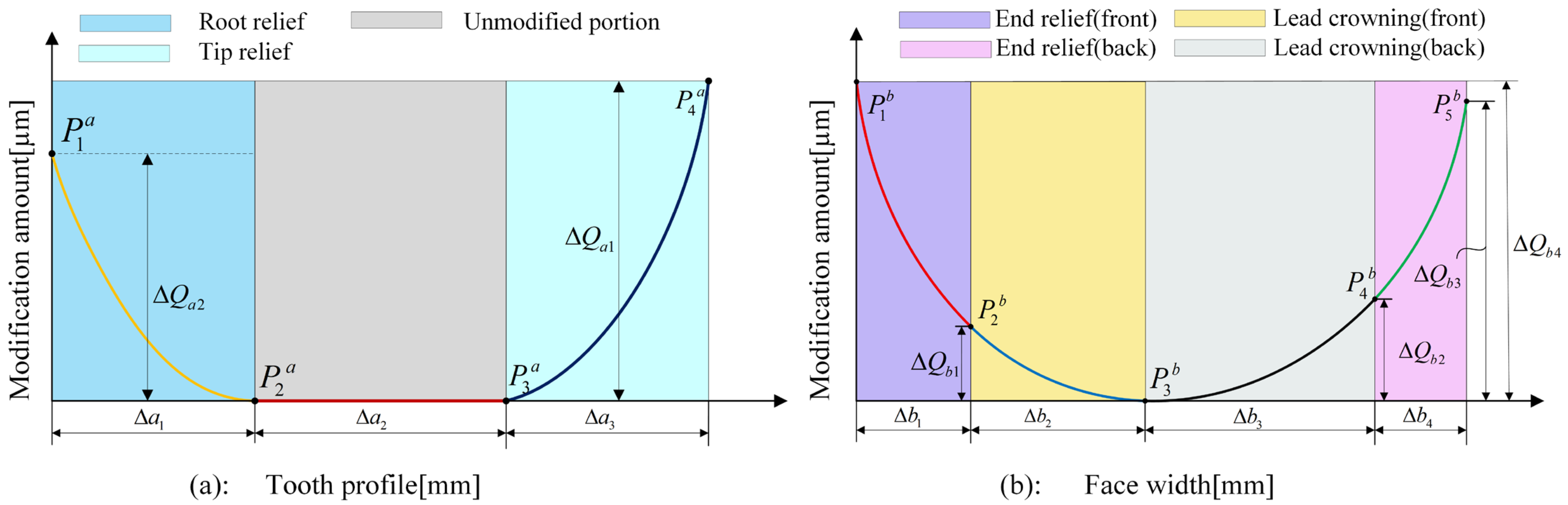
Figure 2 illustrates the schematic diagram of the tooth flanks modification, which composes modification with tooth profile and tooth direction. The tooth profile modification curve consists of two quadratic sections (– and –) joined by a linear segment (–), as shown in Figure 2a. The purpose of this modification is to eliminate edge contact on the top and root of the tooth flank, while maintaining the larger contact area in the middle of the teeth. Additionally, the tooth flank is divided into three regions including the tip relief zone, the unmodified zone, and the root relief zone according to the modification curve along the tooth profile. The maximum tip and root relief magnitudes are defined as and . And the modification distances of tip and root relief are defined as and , respectively. Thus, the expressions of the modification curves of root relief can be derived by
where , , denote the correction coefficients for root relief modification. The expressions of the modification curves of tip relief can be derived by
where , , are the correction coefficients for tip relief modification.
Figure 2.
Schematic diagram of gear tooth flank modification curves: (a) modification curve along the tooth profile; (b) modification curve along the tooth direction.
Figure 2b depicts the modification curve along the tooth direction of tooth flank, which is composed by four quadratic curves that are mutually tangent at points , , and . This modification is designed to eliminate edge contact at the front and back of the tooth flank. The tooth surface is divided into four regions along the tooth width direction: front end relief, back end relief, front lead crowning, and back lead crowning. Specifically, the modification amount at is , the modification amount and distance along face width at are and , the modification amount at are and , the modification amount at are and , and the modification amount at are and . On this basis, the expressions of the corresponding modification curves of the front end relief can be derived by
where , , and are the correction coefficients for the lead crowning curve. And the equations of the front lead crowning are as follows:
where , , and are the correction coefficients for the front lead crowning curve. The expressions of the back lead crowning are as follows:
where , , and are the correction coefficients for the back lead crowning curve. And the equations of the back end relief are provided by
where , , and are the correction coefficients for the back end relief.
With the modification curves for both the tooth profile and tooth direction established above, the 18 unknown correction coefficients are uniquely determined from three boundary conditions imposed on each curve: the specified modification magnitude at its starting and ending points, tangency continuity with the adjacent curves, and zero modification at the unmodified boundary.
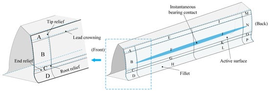
Figure 3 shows the comprehensive tooth surface modification. The tooth flank is partitioned into 16 subregions, where each subregion is assigned independent tooth profile and tooth direction modifications. The total modification magnitude of each subregion is obtained by superposing the corresponding profile and tooth direction modification values.
Figure 3.
Schematic diagram of comprehensive tooth surface modification.
Based on the partitioned subregions, the superposition formula for the asymmetric modification magnitude within each subregion is derived and the modification magnitude of each area can be calculated based on the Table 1. And the subscript Y represents each modification region from A to P. The range of values for each variable u, l, and are determined by the position of the modification curve.
Table 1.
The modification magnitude calculation method for each modifying area.
The modified tooth surface points can be calculated based on the theoretical tooth flank and modification values for each modifying area. The equation formulas of modified tooth flank are derived by
Thus, by solving the above system of equations, the modification parameters of the modification curves for each subregion of the tooth flank are determined. On this basis, the total modification amount of each subregion is calculated from the determined modification parameters and the corresponding variables (u, l, and ). Subsequently, the entire ideal composite modified tooth flank is obtained by integrating the unmodified theoretical tooth flank with the total modification amount of each subregion.
4. Meshing Analysis Model of Cylindrical Helical Gears
Table 2 shows the geometric parameters of the standard gear pair and Table 3 presents the asymmetric modification parameters for pinion and gear. The theoretical mathematical tooth surface is obtained based on the modified tooth flank calculation method and the design parameters. The modified mathematical tooth surface is calculated with the modification parameters.
Table 2.
Basic design parameters of cylindrical helical gears.
Table 3.
Modification parameters of cylindrical helical gears.
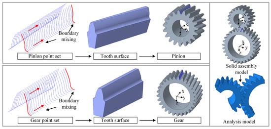
The detailed modeling workflow of analysis model is illustrated in Figure 4. First, MATLAB R2024a software is used to compute the discrete tooth flanks mathematical point clouds of cylindrical helical gears. Then, the tooth flank point sets of the pinion and driven gear are imported into Creo to reconstruct the gear tooth profile, based on which the single-tooth blank model is established. Subsequently, the complete geometric model of the helical cylindrical gear is generated by arraying the single tooth around the gear axis and assembling the components via mating constraints. To improve the computational efficiency of the subsequent finite element simulation, a partial segment of the assembly is extracted for simulation and verification.
Figure 4.
Modeling procedure of the analysis model.
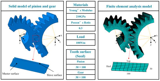
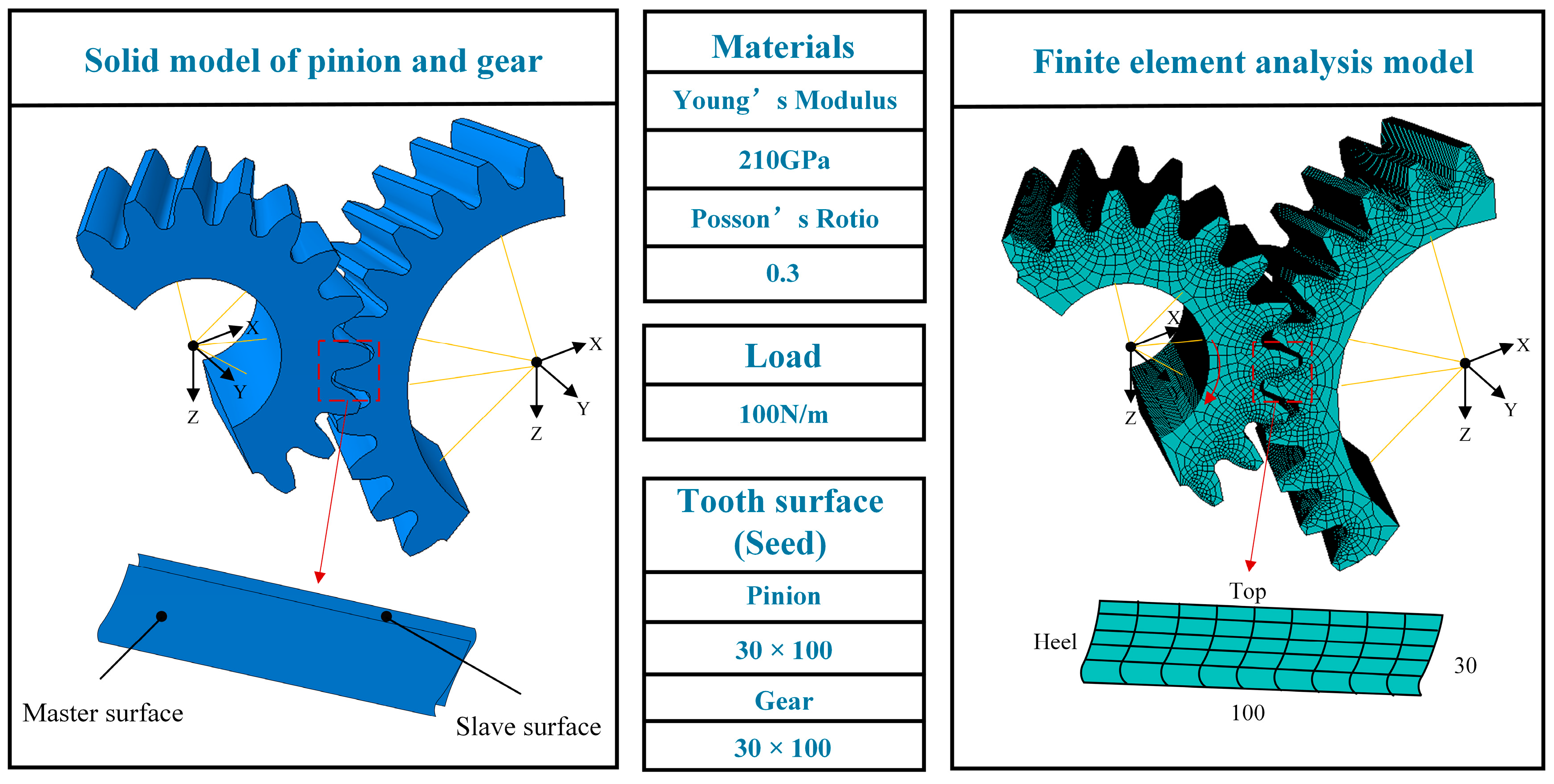
Figure 5 presents the finite element meshing model of the cylindrical helical gear pair. The simulation was performed using Abaqus 2024, and the necessary parameters were configured in the preprocessing module, including material properties, mesh element and node counts, applied load, and boundary conditions. The gear pair was made of 20CrMnTi carburized and quenched steel, and treated as isotropic, with an elastic modulus of 210,000 GPa and a Poisson’s ratio of 0.3. A global seed size of 5 was adopted, and the tooth flank regions were refined with a mesh of 100 × 30 elements. To ensure mesh independence while controlling computational cost, only selected teeth were discretized; the pinion was meshed with approximately 126,000 elements and the driven gear with approximately 128,000 elements, giving about 250,000 elements in total. The analysis was divided into three stages: pre-contact, loading, and meshing. The driving surface was taken as the pinion tooth flank, with a torque of 100 N·m applied, and the contact condition was set as rigid frictionless contact.
Figure 5.
Finite element meshing model of cylindrical helical gears.
5. Comparative Analysis with Asymmetric Tooth Flank Modification
In order to verify the effectiveness of the method, six analysis groups are set up for comparative verification, as shown in Table 4. Specifically, Group 1 is without any modification of gear pairs. Group 2 is central symmetric tooth flank modification, of which the pinion chosen is Standard1 and gear chosen is Case1. Groups 3 to 6 are asymmetric tooth flank modification. The gear chosen from Case2 to Case5 and pinion are the standard type. Group 3 and Group 5 use the left-biased asymmetric modification. Group 4 and Group 6 use the right-biased asymmetric modification.
Table 4.
The experimental analysis groups with tooth flank modification.
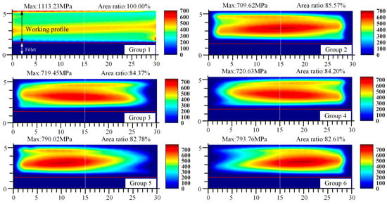
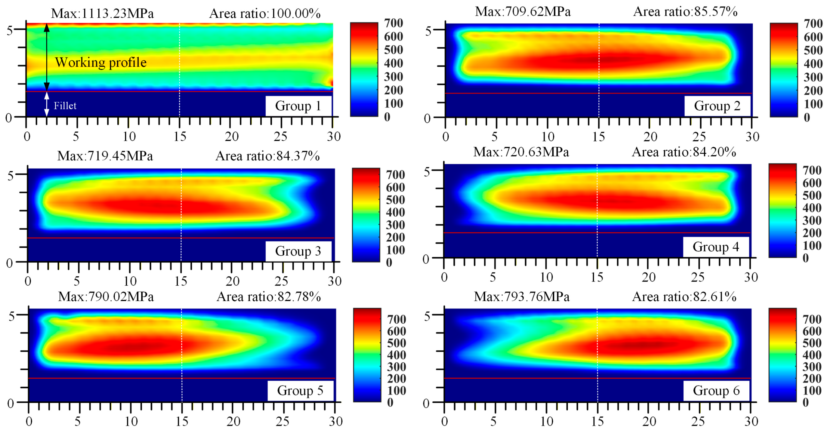
The contact patterns from Group 1 to Group 6 are presented in Figure 6. For Group 1, edge contact occurs at the addendum, dedendum, and both the front and rear ends along the face width direction. The maximum contact stress reaches 1113.2 MPa, with the contact pattern covering 100.00% of the total tooth flank area, and the peak stress is located at the left zone of the addendum. In contrast, edge contact is completely eliminated in Group 2, where the maximum contact stress drops to 709.62 MPa and the contact pattern proportion decreases to 85.57%. Meanwhile, the peak stress position shifts toward the geometric center of the effective working tooth flank.
Figure 6.
Contact patterns from Group 1 to Group 6.
For Groups 3 and 5, which employ asymmetric modification, edge contact is also fully removed, and the peak contact stress moves to a region slightly left of the tooth flank center. Specifically, Group 3 exhibits a maximum contact stress of 719.45 MPa with a high-stress area ratio of 84.37%, while Group 5 shows 790.02 MPa and 82.78%, respectively. Owing to its larger leftward offset magnitude, Group 5 presents more pronounced stress concentration on the left side of the tooth surface, resulting in a higher peak stress. Nevertheless, the high-stress area proportions of these two groups do not differ markedly from that of Group 1.
Groups 4 and 6 exhibit similar levels of maximum contact stress and loaded area ratios to Groups 3 and 5, with the only distinction being that the peak stress location shifts from the left to the right side of the tooth flank center. Compared with symmetric modification, the asymmetric modification scheme maintains comparable contact stress magnitudes and loaded area ranges while substantially enhancing the flexibility in adjusting the peak stress position for meshing cylindrical helical gear pairs.
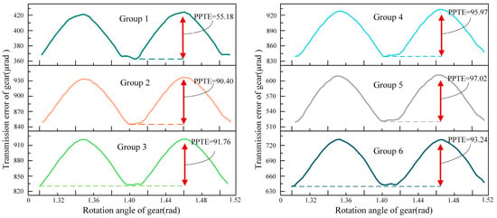
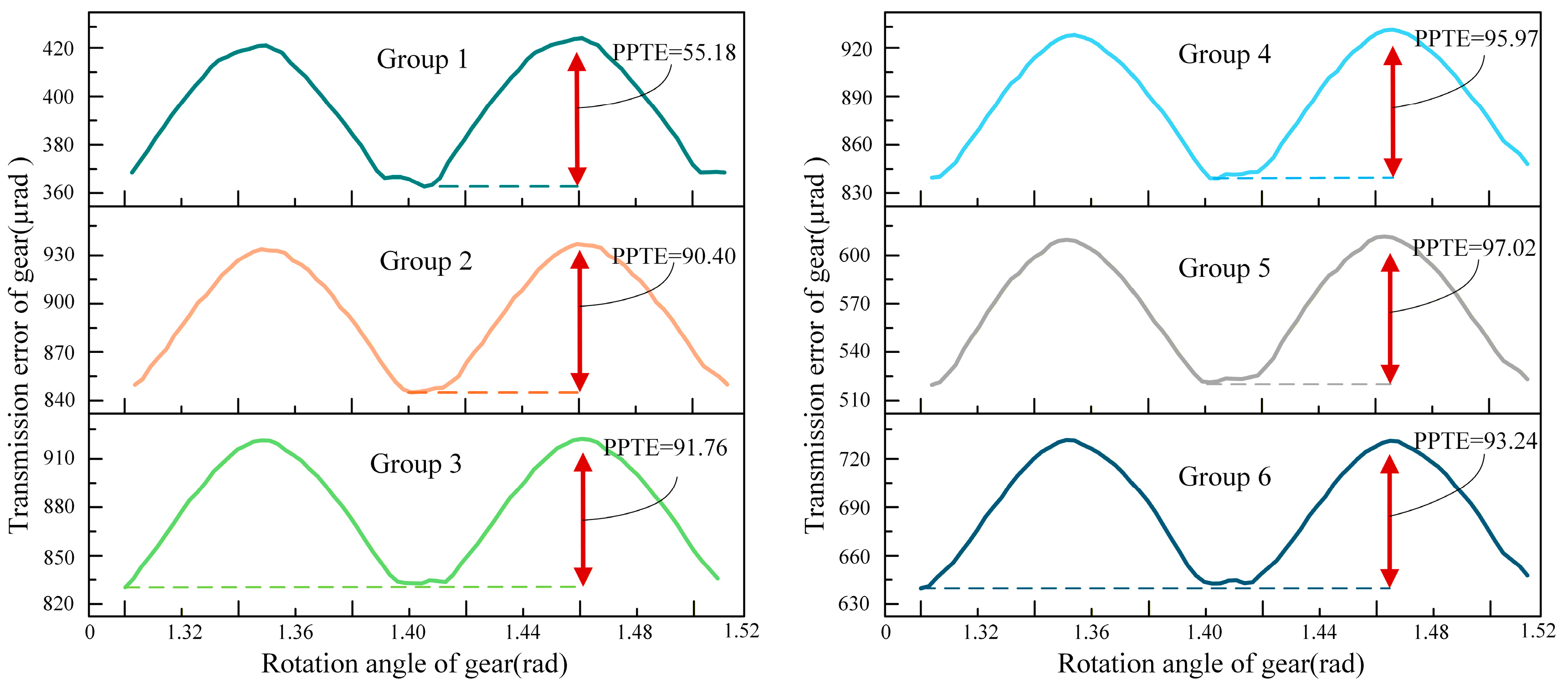
Figure 7 is the comparative result of transmission error from Group 1 to Group 6. For Group 1, the peak-to-peak TE is 55.18 μrad. In contrast, Group 2 with symmetric modification shows a notably increased value of 90.40 μrad. Groups 3 and 5, which adopt leftward asymmetric modification, yield peak-to-peak TE values of 91.97 μrad and 97.02 μrad, respectively. Compared with Group 2, these two configurations maintain a comparable level of transmission error while successfully achieving the primary objective of this study—namely, enhancing the adjust ability of the maximum contact stress location during meshing. Similarly, Groups 4 and 6 exhibit results consistent with those of Groups 3 and 5, with nearly unchanged peak-to-peak TE values; the sole distinction is that the offset direction of the peak stress position is reversed toward the right side of the tooth flank.
Figure 7.
Transmission error from Group 1 to Group 6.
6. Comparative Analysis of Meshing Characteristics Under Installation Deviations
During the actual installation of parallel-axis gears, installation deviations are unavoidable and generally fall into two categories: axial errors and intersection angle errors. These errors significantly alter the meshing performance of the gear pair, thereby adversely affecting its service life. To highlight the advantages of asymmetric tooth modification, a comparative analysis is conducted to evaluate the effectiveness of unmodified, symmetrically modified, and asymmetrically modified gears in controlling meshing performance under installation error conditions. Additionally, the installation deviations are set to axial errors of 2 mm and an intersection angle error of 0.1 degree. Table 5 shows the modification amount of the tooth surface considering installation error.
Table 5.
Modification parameters of cylindrical helical gears with assembly errors.
Table 6 lists the experimental groups designed to investigate the influence of installation deviations on meshing characteristics. Group 7 serves as the baseline, consisting of unmodified gear pairs under installation deviations. Group 8 adopts centrally symmetric tooth flank modification under installation deviations, with the pinion set to Standard2 and the gear set to Case6. Groups 9 and 10 both employ asymmetric tooth flank modification under installation deviations, differing from each other only in the parameter configurations of the asymmetric modification.
Table 6.
The experimental analysis groups with assembly errors.
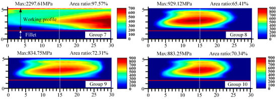
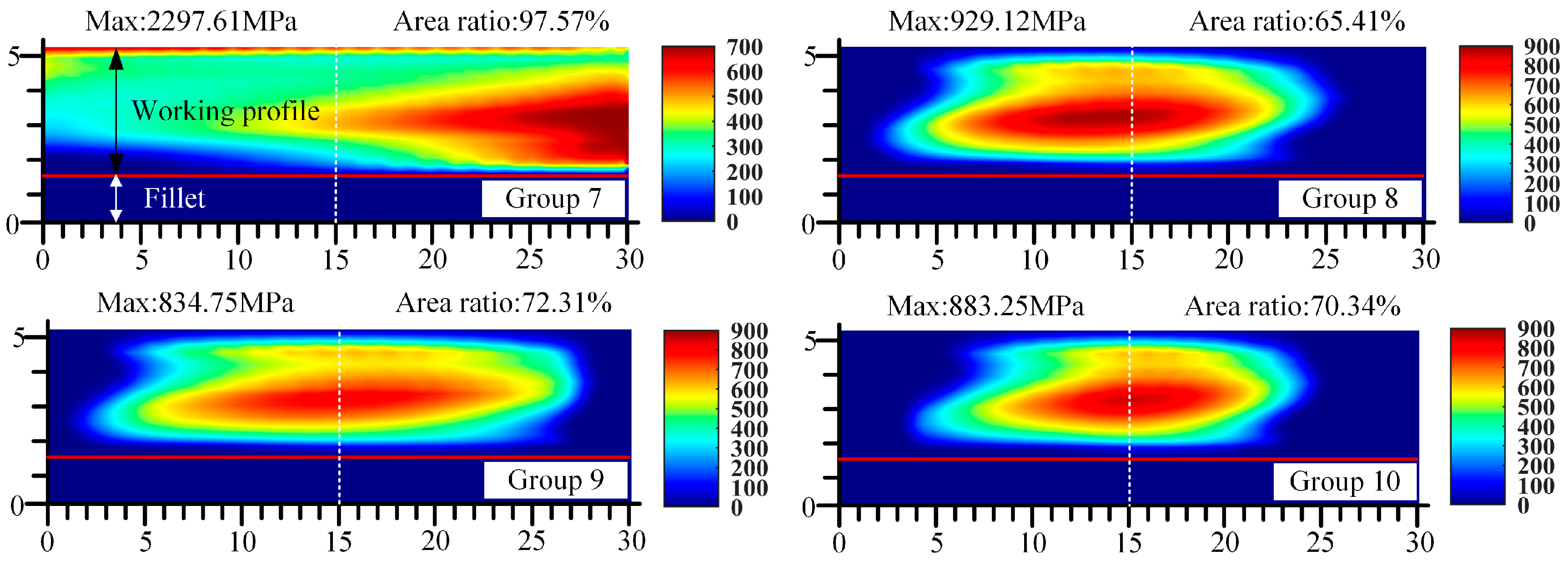
Figure 8 shows the contact patterns from Group 7 to Group 10. In Group 7, edge contact occurs at the addendum, dedendum, and rear ends along the face width. The maximum contact stress rises from 1113.2 MPa to 2297.6 MPa, with its location shifting to the rear end along the face width. By contrast, Group 8 adopts centrally symmetric modification, which completely eliminates edge contact at all four edges and reduces the maximum contact stress to 929.12 MPa, with the area ratio of contact pattern covering 65.41%. However, the location of the maximum contact stress no longer resides at the geometric center of tooth flank. Compared with Group 8, the edge contact elimination is preserved in Groups 9 and 10, both employing asymmetric modification with different parameter settings. In Group 9, the front-end high-stress region remains almost unchanged while the rear-end region is significantly enlarged, leading to a further reduction in maximum contact stress to 834.75 MPa (from 929.12 MPa) and an increase in the high-stress proportion to 72.31%. In Group 10, the stress peak shifts back to the geometric center of the effective flank, with the maximum stress decreasing to 883.25 MPa (from 929.12 MPa) and the high-stress proportion rising to 70.34%.
Figure 8.
Contact patterns of Group 7–Group 10 considering installation deviations.
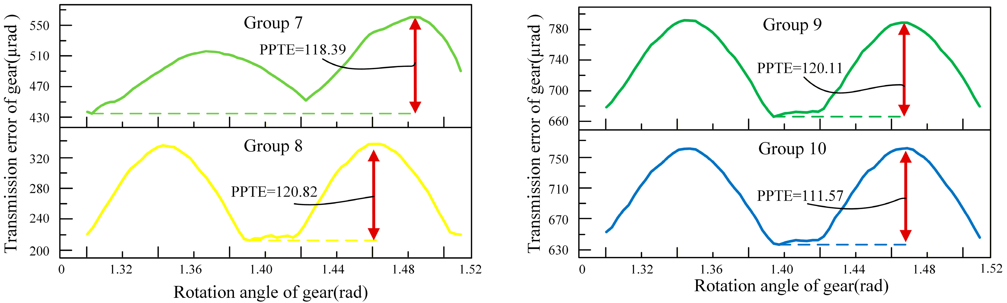
Figure 9 illustrates the transmission error from Group 7 to Group 10. In Group 7, the transmission error of the gear pair exhibits an irregular pattern under the influence of assembly errors. In Group 8, the regularity of the meshing transmission error is restored, and the peak-to-peak value is recorded as 120.82 μrad. For Groups 9 and 10, the peak-to-peak values of the transmission error are 120.11 μrad and 111.57 μrad, respectively. Compared with Group 8, the flexibility in adjusting the contact stress position on the meshing tooth flank is enhanced in both asymmetric groups, while the peak-to-peak value of the meshing transmission error remains essentially unchanged.
Figure 9.
Transmission error of Group 7–Group 10 considering installation deviations.
7. Conclusions
This paper proposes a method for evaluating the meshing performance of cylindrical helical gear pairs with an offset meshing centerline under comprehensive asymmetric modification. The main conclusions are summarized as follows:
- (1)
- A mathematical model of cylindrical helical gears with ideal composite asymmetric tooth flank modification is established based on the theoretical gear model, and modification amounts are assigned to 16 subregions along the tooth profile and face-width directions. The calculation method for asymmetric tooth flank modification is derived, and the analytical expressions for arbitrary modified regions are presented.
- (2)
- Six analysis models are configured to simulate the meshing characteristics of cylindrical helical gears under different modification methods and amounts. Simulation results indicate that, similar to symmetric modification, asymmetric modification is capable of completely eliminating edge contact, maintaining the peak-to-peak transmission error at a nearly constant level, reducing the maximum contact stress, and concentrating the peak stress within the central region of the effective working flank.
- (3)
- Four analysis models are established to simulate the meshing characteristics of cylindrical helical gears under different modification methods and amounts in the presence of assembly errors. Asymmetric modification offers greater flexibility in controlling the magnitude and location of the contact imprint by enabling controlled edge contact on the tooth flank.
The present model, however, assumes ideal tooth flanks and focuses on static contact behavior; manufacturing deviations, mesh stiffness variation, and dynamic effects are not yet incorporated. Future work will further investigate how modification parameters govern the meshing performance by accounting for manufacturing deviations, time-varying mesh stiffness, and the transverse contact ratio.
Author Contributions
P.W. was in charge of the entire simulation results, C.L. wrote the code and manuscript, and L.L., Q.H., and S.L. revised the manuscript. All authors have read and agreed to the published version of the manuscript.
Funding
The authors would like to thank the National Natural Science Foundation of China (52405060), the Natural Science Foundation of Jiangxi Province (Grant Nos. 20242BAB20199, 20262BAC240203), and the Early Vocational Youth Science and Technology Talent Training Project of Jiangxi Province (Grant No. 20244BCE52123).
Data Availability Statement
The original contributions presented in this study are included in the article. Further inquiries can be directed to the corresponding author.
Conflicts of Interest
Author Qianhong Huang was employed by the company Guilin Fuda Co., Ltd. The remaining authors declare that the research was conducted in the absence of any commercial or financial relationships that could be construed as a potential conflict of interest.
References
- Liu, S.; Chen, X.; Song, C.; Zhu, C.; Bai, H.; Fuentes-Aznar, A. Influence of gear–shaft interference fit assembly on the meshing characteristics of cylindrical gears considering comprehensive modifications. Mech. Mach. Theory 2023, 182, 105247. [Google Scholar] [CrossRef] [Scilit]
- Niemann, G.; Winter, H. Maschinenelemente: Band 2: Getriebe Allgemein, Zahnradgetriebe—Grundlagen, Stirnradgetriebe, 2nd ed.; Springer: Berlin/Heidelberg, Germany, 1983. [Google Scholar]
- Fetvaci, M.C. Determination of effective involute parameter limit in generation simulation of gears manufactured by rack-type cutters. Mech. Ind. 2017, 18, 405. [Google Scholar] [CrossRef] [Scilit]
- Jia, H.; Qin, D.; Liu, C. Novel tooth modification methodology for multistage spur gears considering dynamic deformation of housing. J. Mech. Eng. Sci. 2019, 233, 7257–7269. [Google Scholar] [CrossRef] [Scilit]
- Autiero, M.; Paoli, G.; Cirelli, M.; Valentini, P.P. The effect of different profile modifications on the static and dynamic transmission error of spur gears. Mech. Mach. Theory 2024, 201, 105752. [Google Scholar] [CrossRef] [Scilit]
- Liang, C.; Zhang, Y.; Liu, L.; Liu, R. Analytical study on meshing performance of helical cylindrical gears with the coupling of tooth flank morphology and installation error. J. Adv. Mech. Des. Syst. Manuf. 2025, 19, JAMDSM0037. [Google Scholar] [CrossRef] [Scilit]
- Liu, Y.; Ma, D. Surface modification and tooth contact analysis of variable hyperbolic circular-arc-tooth-trace cylindrical gears. Mech. Sci. 2022, 13, 909–920. [Google Scholar] [CrossRef] [Scilit]
- Qiu, P.; Zhao, N.; Peng, Y.; Lin, Y. Analysis of tooth contact for cylindrical gear with high-order topological modification and misalignment. J. Vibroeng. 2022, 25, 189–208. [Google Scholar] [CrossRef] [Scilit]
- Sánchez, M.B.; Pleguezuelos, M.; Pedrero, J.I. Influence of profile modification on the transmission error of spur gears under surface wear. Mech. Mach. Theory 2024, 191, 105473. [Google Scholar] [CrossRef] [Scilit]
- Gao, P.; Liu, H.; Yan, P.; Xie, Y.; Xiang, C.; Wang, C. Research on application of dynamic optimization modification for an involute spur gear in a fixed-shaft gear transmission system. Mech. Syst. Signal Process. 2022, 181, 109530. [Google Scholar] [CrossRef] [Scilit]
- Ghosh, S.S.; Chakraborty, G. On optimal tooth profile modification for reduction of vibration and noise in spur gear pairs. Mech. Mach. Theory 2016, 105, 145–163. [Google Scholar] [CrossRef] [Scilit]
- Pedrero, I.J.; Pleguezuelos, M.; Sánchez, B.M. Influence of surface wear on the meshing stiffness and transmission error of internal spur gears with profile modification. Forsch. Ing. 2025, 89, 154. [Google Scholar] [CrossRef] [Scilit]
- Ma, D.; Ye, Z. Nonlinear dynamic characteristics of modified variable hyperbolic circular arc tooth trace cylindrical gears. Sci. Rep. 2025, 15, 15108. [Google Scholar] [CrossRef] [Scilit]
- Sun, J.; Liu, H.; Chen, Z.; Tang, Z.; Lu, M. Research on Noise Reduction Modification Design of High Speed EMU Traction Arc Toothed Cylindrical Gears. Appl. Sci. 2023, 14, 144. [Google Scholar] [CrossRef] [Scilit]
- Dias, F.H.; Silva, G.C.; Chui, D.S. Vibration attenuation on spur gears through optimal profile modification based on an alternative dynamic model. J. Braz. Soc. Mech. Sci. Eng. 2023, 46, 10. [Google Scholar] [CrossRef] [Scilit]
- Vivek, R.; Kumar, N.J.; Sunil, P. Mathematical modelling and validation of twist-free lead crowning of spur gears by pulsed electrochemical flank modification process. Int. J. Adv. Manuf. Technol. 2023, 129, 2309–2331. [Google Scholar] [CrossRef] [Scilit]
- Abruzzo, M.; Beghini, M.; Romoli, L.; Santus, C. Design for manufacturing of a spur gears profile modification based on the static transmission error for improving the dynamic behavior. Int. J. Adv. Manuf. Technol. 2023, 129, 1999–2010. [Google Scholar] [CrossRef] [Scilit]
- Pedrero, J.I.; Pleguezuelos, M.; Sánchez, M.B. Analysis of the tip interference in low gear ratio internal spur gears with profile modification. Forsch. Ing. 2023, 87, 891–900. [Google Scholar] [CrossRef] [Scilit]
- Zou, D.; Wang, L.; Yang, L.; Yu, W.; Xie, L. Dynamic characteristics of a spur gear pair under the coupled effects of angular misalignment fault and tooth modification. Int. J. Non-Linear Mech. 2023, 155, 104453. [Google Scholar] [CrossRef] [Scilit]
- Zhao, Z.; Yang, Y.; Ma, H.; Wang, H.; Tian, H.; Han, C. Meshing characteristics of spur gear pairs with tooth modification under different assembly errors and sensitivity analysis for impact factors. J. Mech. Sci. Technol. 2022, 37, 149–162. [Google Scholar] [CrossRef] [Scilit]
- Rana, V.; Jain, N.K.; Pathak, S. Improving functional performance characteristics of spur gears through flank modifications by non-contact advanced finishing process. Int. J. Adv. Manuf. Technol. 2022, 124, 1787–1811. [Google Scholar] [CrossRef] [Scilit]
- Li, D.; Liu, Y.; Gong, J.; Wei, Y.; Zhao, G. A novel method for longitudinal modification and tooth contact analysis of non-circular cylindrical gears. J. Mech. Sci. Technol. 2022, 36, 6157–6170. [Google Scholar] [CrossRef] [Scilit]
- Abruzzo, M.; Beghini, M.; Santus, C.; Presicce, F. A dynamic model combining the average and the local meshing stiffnesses and based on the static transmission error for spur gears with profile modification. Mech. Mach. Theory 2023, 180, 105139. [Google Scholar] [CrossRef] [Scilit]
- Zhou, R.; Luo, B.; Li, W. A new dynamics modeling method for a spur gear pair with tooth profile modification. J. Braz. Soc. Mech. Sci. Eng. 2022, 44, 438. [Google Scholar] [CrossRef] [Scilit]

Disclaimer/Publisher’s Note: The statements, opinions and data contained in all publications are solely those of the individual author(s) and contributor(s) and not of MDPI and/or the editor(s). MDPI and/or the editor(s) disclaim responsibility for any injury to people or property resulting from any ideas, methods, instructions or products referred to in the content. |
© 2026 by the authors. Licensee MDPI, Basel, Switzerland. This article is an open access article distributed under the terms and conditions of the Creative Commons Attribution (CC BY) license.