


Abstract
This study conducts a preliminary FE simulation of screw piercing and screw rolling processes for producing bimetallic pipes with variable inner and outer positioning and thickness of the corrosion-resistant steel CL (13Cr and 18Cr10Ni grades) as a rational first step before experimental testing. The results demonstrate that a favorable stress–strain state is formed in both processes under the selected deformation parameters (there are no high tensile stresses in the area of high strains and low temperatures). Shape change analysis confirmed that the pipe geometric dimensions according to simulation are sufficiently close to the target values, with only minor deviations in wall thickness and ovality. The change in CL thickness during piercing ranges from 34% to 51% and increases with the elongation ratio. In the rolling process, it reaches approximately 55–56%. The CL position, its thickness and the material choice significantly influence the deformation heating intensity within the bonding of base and clad materials, as well as the magnitude of the forces acting on the tool in contact with the CL. The obtained results can serve as a methodology that lays the groundwork for experimental verification and the further technology implementation, while minimizing risks and costs.
1. Introduction
Modern engineering and technological challenges associated with improving the efficiency, reliability, and service life of structural components increasingly require the use of materials with a combination of diverse functional properties. One of the most promising solutions to this challenge is the application of composite materials. Composites, which are intentionally engineered from two or more dissimilar components, enable the synergistic integration of the desirable characteristics of each constituent, thereby providing superior performance compared to conventional materials. Within this class, metallic composite, in particular, bimetallic pipes, occupy a special position [1,2,3,4].
Bimetallic pipes, which combine two or more dissimilar metallic layers into a single composite structure, are key components in modern industry. The integration of properties such as the corrosion resistance of stainless steel with the cost-effectiveness and high strength of carbon steel provides these pipes with outstanding service characteristics in demanding applications. Bimetallic pipes play a critical role in the energy sector, oil and gas extraction, chemical engineering, and heat-exchange equipment, where they make it possible to extend service life, enhance operational safety, and reduce overall lifecycle costs [5,6,7,8,9].
The production of such pipes is commonly based on metal forming technologies, among which screw rolling processes and, when necessary, subsequent cold working operations (rolling or drawing) are the most effective [10,11,12,13]. However, the complexity of thermal conditions and the specific features of the stress–strain state during screw rolling [14,15,16,17] make empirical optimization both costly and time-consuming and do not allow comprehensive analysis of parameters such as final layer thickness ratio, residual stress distribution, and potential defect formation. Therefore, finite element method (FEM) simulation is an indispensable tool. A properly developed FEM model enables researchers to investigate the mechanics of the process, adjust the virtual forming parameters, and consequently determine rational processing conditions prior to experimental trials [18,19,20,21]. Through simulation, it becomes possible to predict the evolution of strain, stress, and temperature fields that are difficult or impossible to analyze by experimental methods alone.
For instance, Tomczak et al. [22] employed FEM to analyze billets composed of an outer layer of X5CrNi18-10 steel and cores made of C45 carbon steel and S355/42CrMo4 during skew rolling. In subsequent research, Kusiak et al. [23] demonstrated that preliminary FEM simulation of screw rolling for producing axisymmetric bimetallic billets (C60/S355) allowed for detailed assessment of temperature distribution and stress–strain state across the cross-section, including the weld interface, thereby confirming the feasibility of this method. In the studies [24,25], simulations of rolling a bimetallic bar made of C45 steel with an external 306L stainless steel layer in a three-roll mill at feeding and rolling angles of 18° and 9°, respectively, were presented; the effects of varying tool speeds and diameters on the distribution of temperature and strain rate, as well as the stress–strain state, were investigated. Le Zhu et al. [26] used FEM simulation to examine bonding quality and deformation behavior in cross-wedge rolling of bimetallic hollow shafts on a mandrel with different diameters. Jianhua Hu et al. [27] developed an optimization method that integrates numerical simulation and intelligent algorithms to improve product quality during skew piercing of bimetallic composite pipes (Incoloy825/P110), based on FEM analysis of the defect formation mechanism.
As part of studies on pre-bending and JCO forming of pipes manufactured from bimetallic plate (2205/X65), Zhiqiang Dong et al. [28] developed a three-dimensional model of the process and performed analysis of stress distribution within the pipe as well as at the material interface. The simulation also enabled evaluation of the influence of sheet geometry and processing parameters, and the results were in good agreement with experimental data. Nevertheless, despite the significant interest in bimetallic products, the literature provides limited research on FEM simulation of screw piercing and rolling of pipes from dissimilar bimetallic materials. To produce the initial bimetallic workpiece, explosive welding can be used [29,30], which creates a strong bond between the layers through plastic deformation caused by the combined effects of high pressure and the speed of their collision. Subsequent screw piercing or screw rolling will make possible the production of long pipes with specified geometric dimensions, as well as improved microstructure and mechanical properties through hot deformation. Considering that the explosive welding method requires careful preparation and special equipment, a preliminary simulation to assess the correctness of the selected rolling modes in terms of the feasibility of the screw piercing and rolling is of practical importance and allows for a reduction in costs at the initial stage of research. The feasibility of using screw rolling for the production of bimetallic tubes from workpieces obtained by explosive welding (08Kh18N10T stainless steel + 20 grade carbon steel) has previously been demonstrated by the authors, based on computer simulation and subsequent experimental testing [31]. The obtained data demonstrated a high convergence between the developed FE model and the experimental data. However, the selection of layer material, their initial size ratio (thickness), and positioning in the workpiece for screw rolling conditions remain important issues, which can be assessed in the early stages of work based on computer simulation data.
Thus, the main objective of this study is to conduct a preliminary assessment of the screw piercing and rolling processes using the finite element method (FEM) as potential methods for manufacturing bimetallic seamless pipes with a corrosion-resistant cladding layer. In particular, using in the simulation the workpieces produced by explosive welding, we aim to characterize the temperature fields and stress–strain states that arise during processing, and to determine the influence of the cladding layer thickness on the critical process parameters.
2. Materials and Methods
In this study, the piercing and rolling processes are considered as separate technological routes for production of pipes from different types of initial workpieces. To obtain an outer corrosion-resistant cladding layer, the piercing process using a solid workpiece is more appropriate. Conversely, when an inner cladding layer is required, a pipe workpiece can be employed. The selection of materials and the positioning of the cladding layer (inner or outer) were determined by the possible operating conditions of the pipes. For the analysis of the piercing process, a solid workpiece was selected with a carbon steel (AISI 1045) core and an outer layer made of Cr13 type stainless steel (AISI 420). For the rolling process, a pipe workpiece with an outer base layer of steel 45 and an inner layer of Cr18Ni10 type stainless steel (AISI 321) was utilized. The combination of these materials is often used for production of the bimetallic pipe production for the chemical industry, heat exchangers, and other equipment as an alternative to costly pipes made of high-alloy steels and alloys.
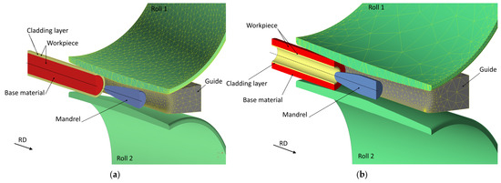
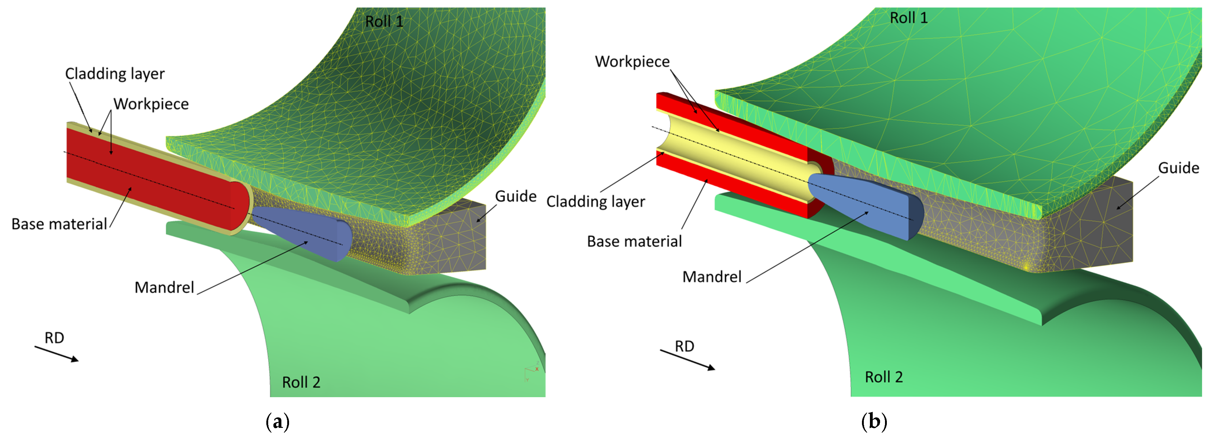
The simulation was conducted using the QForm v10.3 software package. Three-dimensional models prepared in the SolidWorks CAD system (version 2020) included rolls, guides, mandrel, and workpieces consisting of two metallic layers. These models were subsequently imported into QForm (Figure 1).
Figure 1.
Three-dimensional models of the deformation zone for (a) piercing and (b) rolling.
The simulation was performed with the initial workpiece temperature set at 1180 °C, the rotation velocity of the rolls set at 57 rpm, and a feed angle of 10°.
Table 1 presents the main parameters used in the FEM simulation of both screw piercing and rolling processes. To solve a three-dimensional problem with complex kinematic motion, a finite element mesh in the form of tetrahedrons was used. To achieve sufficient calculation accuracy and maintain a balance between time costs and accuracy, the model utilized the finite element mesh adaptation parameters specified in Table 1. In particular, a minimum number of elements per thickness (n = 4) was specified for the cladding layer. Local adaptation of the FE mesh was set for the contact zone between the tool and the workpiece, which improves the accuracy of parameter calculations in the deformation zone and reduces calculation time. To solve systems of nonlinear equations that form a mathematical model of a deformed workpiece during FEM calculations, the method of simple iterations is used, the essence of which lies in constructing a sequence of solutions (iterations) that converge to an exact solution with a certain accuracy. The norms of increments due to velocities (main parameter) and average stresses (auxiliary parameter) amount to 3% and 30% respectively of the current norm values for the corresponding quantities. The maximum number of iterations is defined as 20.
Table 1.
Main parameters of FEM simulation of piercing and rolling processes.
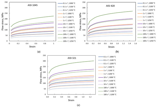
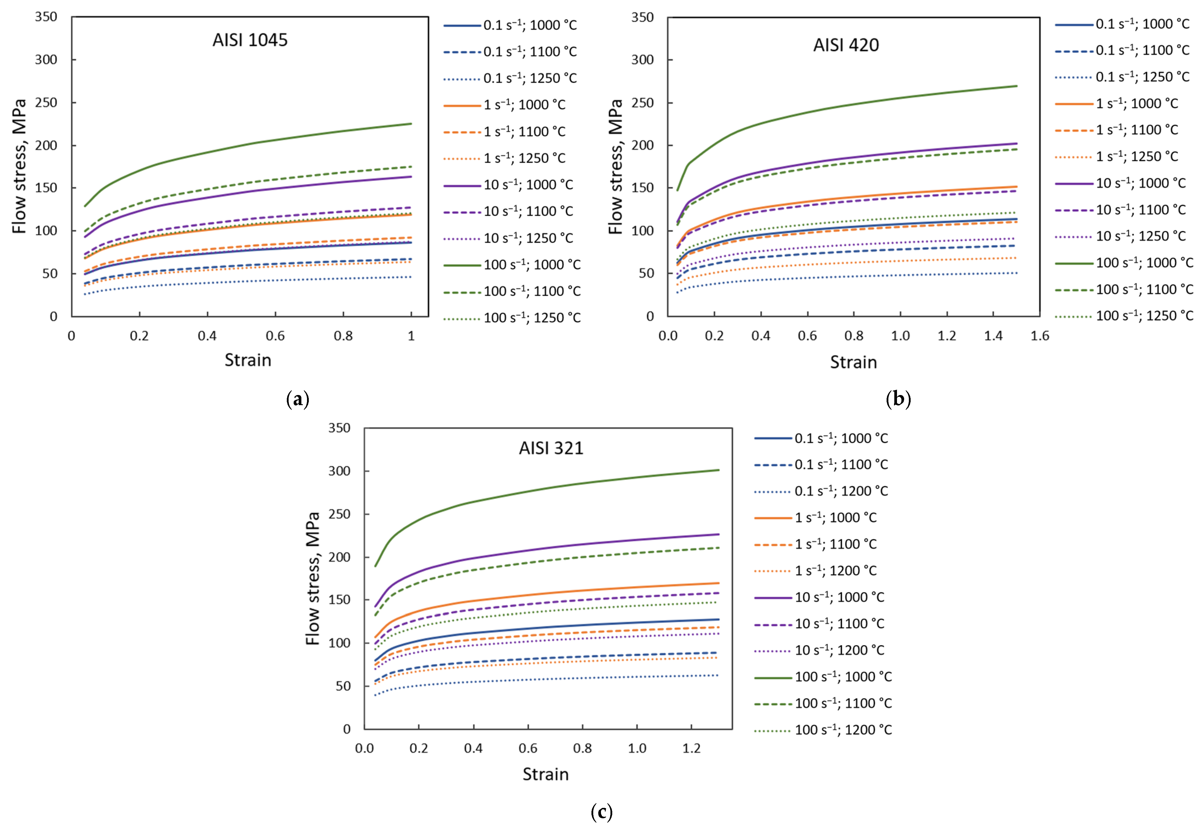
The rheological properties of each material were selected from the QForm database (Figure 2). QForm is able to simulate the combined deformation of multiple bodies. When simulating such processes, the contact surfaces of the bodies must not interpenetrate. Since the FE mesh nodes in contacting bodies generally do not coincide, the condition is not directly usable. A special contact element was used for the numerical implementation. One node of this element is connected to a node located on the contact surface of one body, and the other three are connected to nodes of the second contacting body, forming a triangle within which the first node falls. To simulate the two-layer workpiece produced by explosive welding, the contact surface between the layers was assigned a “Sticking without separation” boundary condition to prevent any relative motion at the interface nodes. This boundary condition was the same for screw piercing and screw rolling.
Figure 2.
Stress–strain curves of materials of workpiece and pipe workpiece: (a) carbon steel AISI 1045, (b) stainless steel AISI 420, and (c) stainless steel AISI 321.
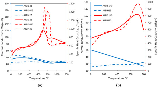
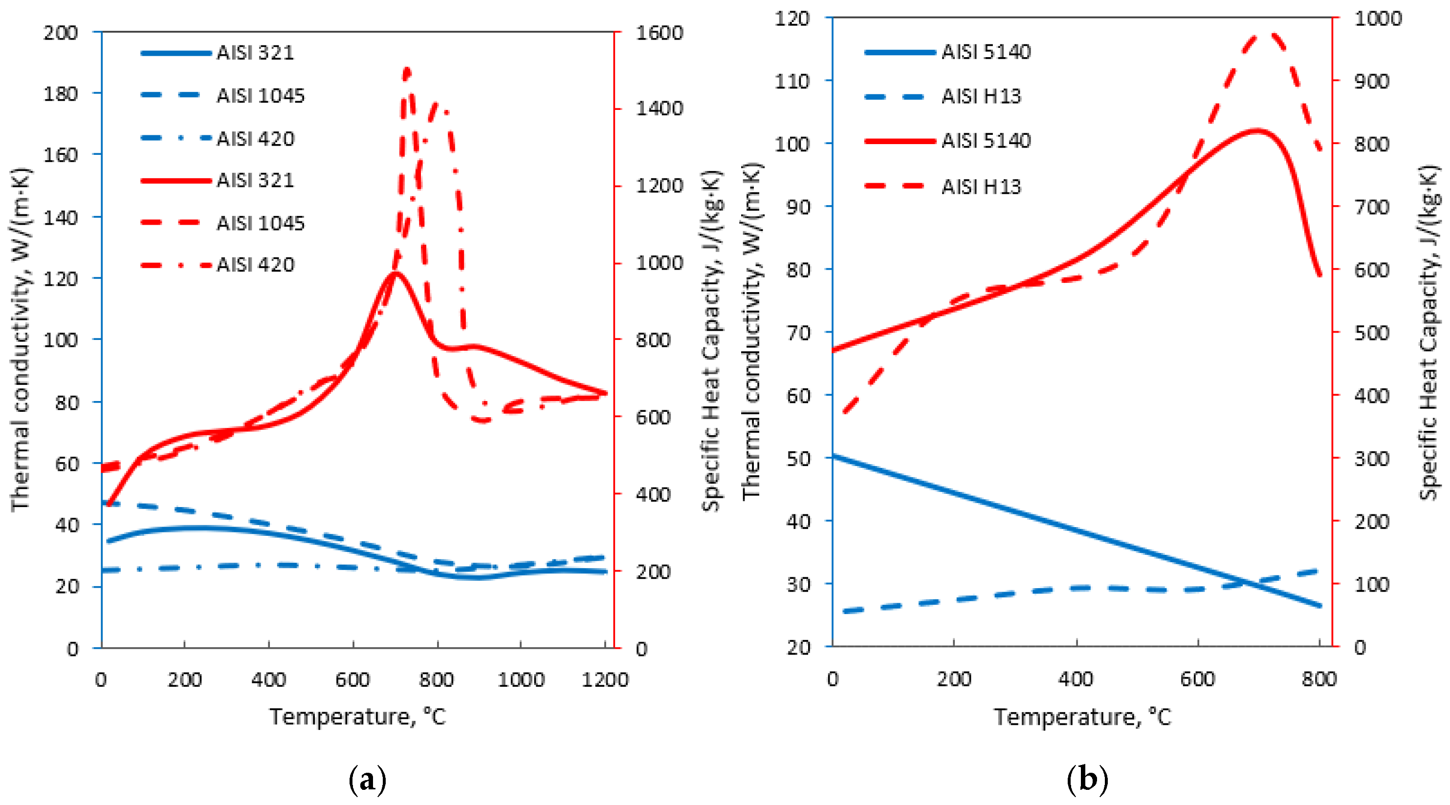
Figure 3 presents the thermophysical properties of the materials of the workpieces and tools during the simulation of the screw piercing and rolling processes, which were specified from the QForm material database and literature data [32,33,34].
Figure 3.
Thermophysical properties of materials of (a) workpieces and (b) tools.
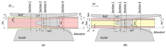
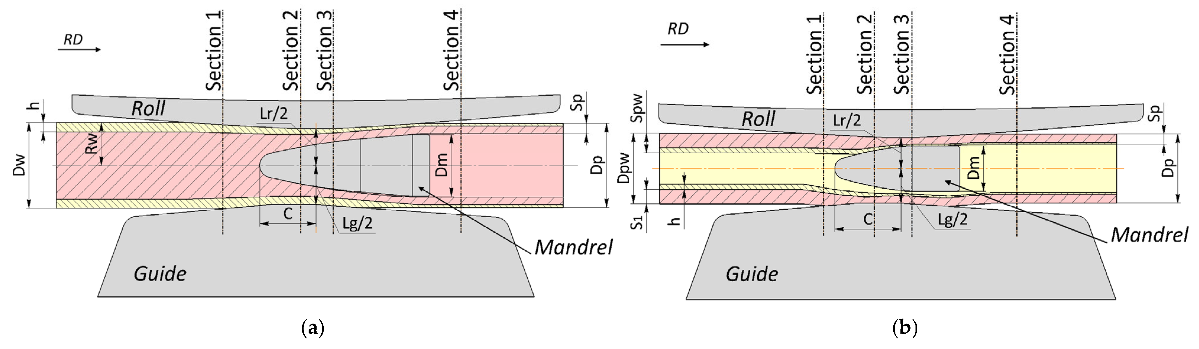
The main geometric dimensions of the workpieces and the deformation modes for piercing and rolling are presented in Table 2 and Table 3 and Figure 4a,b, respectively. The geometric dimensions of the workpieces and pipes were selected based on the industrial range of bimetallic pipes, as well as the possibility of conducting subsequent experimental studies under the conditions of the existing pilot industrial equipment (MISIS-130D two-roll screw rolling mill, OJSC EHMBP, Moscow, Russia) [35].
Table 2.
Geometric dimensions of initial workpieces.
Table 3.
Deformation modes and settings of deformation zone.
Figure 4.
Scheme of deformation zone settings and characteristic cross-sections in deformation zone at (a) screw piercing and (b) screw rolling.
Dw, Dpw and Lw, Lpw are the outer diameter and length of the workpieces, respectively, mm; h is the initial cladding layer (CL) thickness, mm; S1 and Spw are the thickness of base material layer (BL) and wall thickness (WT) of the workpiece, respectively mm; δ is the ratio of layers in the workpiece/pipe workpiece; Sp is the wall thickness of the pipe after piercing/rolling, mm; µ is the elongation ratio; Lr is the distance between the rolls, mm; Lg is the distance between the guides, mm; Urg is the reduction in the gorge, %; C is the distance between mandrel nose and gorge, mm; ξ = Lg/Lr is the ovalization coefficient; and Dm is the mandrel diameter, mm.
In the simulation the Siebel model was used to represent friction in [36]. The shear stress was determined as (1):
where m is the friction factor and K is the material consistency, which is determined with the material flow stress by (2):
The friction factors were m = 0.9 for the rolls and m = 0.2 for the guides and the mandrel.
The stress–strain state of the metal during hot deformation is characterized by the following parameters: equivalent stress (3), mean stress (4), and equivalent strain (5):
where σ1, σ2, and σ3 are the principal stresses.
where —strain rate intensity, 1/s.
The heat exchange in the tool/workpiece contact zone was taken into account using the non-steady-state heat conductivity Equation (6):
where k is the heat conductivity coefficient, W/(m·K); T is the temperature field, K; qG is the internal heat source power, W/m3; Δ is the Laplacian operator; ρ is the density, kg/m3; c is the heat capacity, J/(kg·K); and is derivative of the temperature with respect to time.
Convective heat exchange between the workpiece and the air is described by the Newton–Richman law (7):
where h is the heat-exchange coefficient, W/(m2·K); T1 is the workpiece temperature; and Tc is the ambient temperature.
Radiative heat exchange is described by the following Formula (8):
where ε is the real body blackness (emissivity factor), which is defined as the ratio between the radiative capacities of the body and the absolutely black body at the same temperature (ε = 0.8 for stainless steel and ε = 0.89 for carbon steel), and is the Stefan–Boltzmann constant.
Due to the capabilities of QForm, based on mathematical descriptions of metal forming processes and Equations (3)–(8), the distributions of stress, strain, and temperature fields were analyzed in the deformation zone across the longitudinal section and four characteristic cross-sections: Section 1—contact of rolls and material (primary roll gripping); Section 2—in the middle of piercing/rolling zone of mandrel; Section 3—roll gorge; and Section 4—at the exit from the deformation zone, as illustrated in Figure 4.
Additionally, forces on the tools and geometric parameters, including pipe diameter (average of four points) and layer thickness after piercing and rolling, were evaluated based on the simulation results.
3. Results and Discussion
3.1. Piercing
Table 4 presents the geometric parameters of pipes after the piercing process for initial cladding layer thicknesses of h = 3 mm and h = 5 mm. In both cases, the outer diameter of the pipes is close to the calculated values (see Table 3) and ranges between 55 and 57 mm. The deviation does not exceed ±0.04–0.07 mm, indicating minimal ovality and validating the correct selection of deformation zone settings. The pipe wall thickness exceeds the theoretical value by an average of 0.35–0.47 mm, with a deviation of no more than ±0.15 mm.
Table 4.
Geometric dimensions of pipes after piercing at different initial cladding layer thicknesses.
The results indicate that the relative reduction in the cladding layer depends on its initial thickness. During piercing, the reduction in cladding layer thickness amounts to 51% for h = 5 mm and 34% for h = 3 mm. The ratio of cladding layer to the base material layer after piercing is 0.37 for h = 3 mm, and 0.49 for h = 5 mm. As shown later, this difference is associated not only with the elongation ratio, but also with the temperature–deformation conditions within the deformation zone.
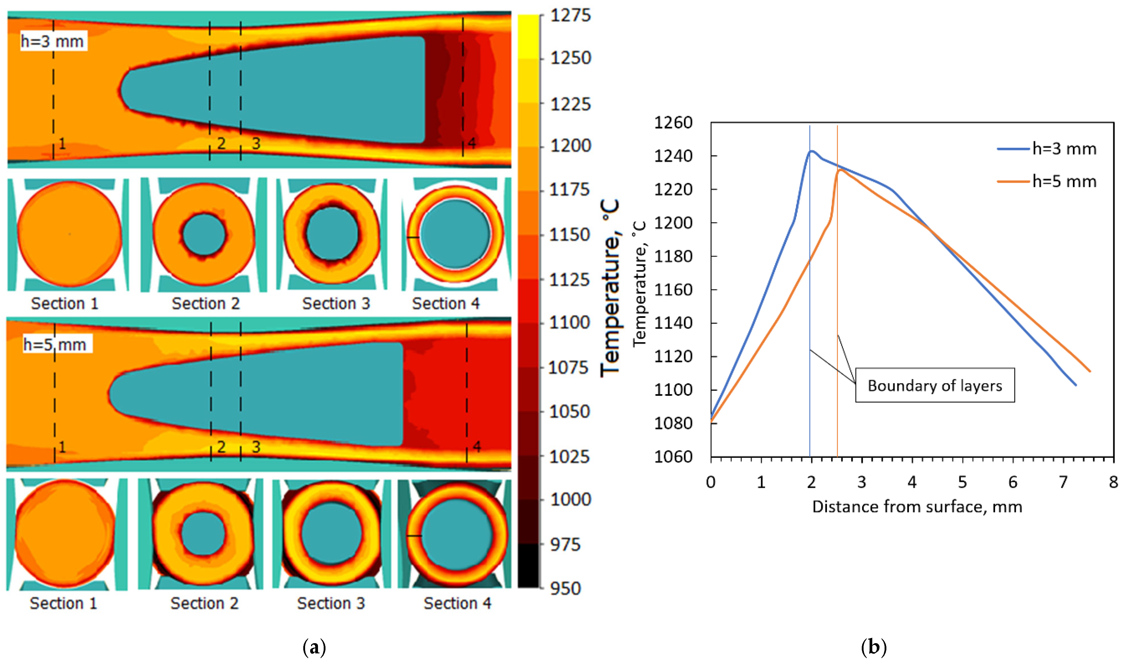
Next, an analysis of the temperature field and stress–strain state was carried out. According to the simulation results, for both initial CL thicknesses (h = 3 and 5 mm), the highest temperature was observed at the boundary of the layers (Figure 5). In contrast, a thin layer with lower temperature (~1000 °C) was formed at the contact surfaces with the rolls and mandrel. From the roll gorge region (Section 3, Figure 5a) to the exit from the deformation zone, intensive heating of the inner layers occurred, resulting in a temperature profile at the outlet characterized by a heated annular inner zone and cooler outer surfaces (Section 4).
The temperature distribution across the pipe wall thickness at the exit (Figure 5b) exhibited a dome-shaped pattern, with temperature values increasing by 50–60 °C at the interface between the cladding and base metals relative to the initial heating temperature. The temperature gradient within the cladding layer averaged 150 °C, and approximately 130 °C in the base layer.
The temperature field near the layer boundary is influenced by parameters such as heat transfer across the interface and stress and strain states. Since materials have different resistance to deformation, the dissipation of potential energy due to deformation differs between the layers under consideration. At the same time, the outer surfaces in contact with the cold tool always have a lower temperature due to natural heat exchange, so the sources of heat generation are concentrated near the boundaries. It is well established that with increasing temperature, dynamic softening processes in metals intensify, which is considered a safer deformation mode in terms of crack initiation and loss of ductility [37,38]. On the other hand, a sharp increase in temperature above the threshold value in the shear deformation zone, typical of screw rolling, can lead to delamination in this region. This fact should be taken into account when designing deformation modes.
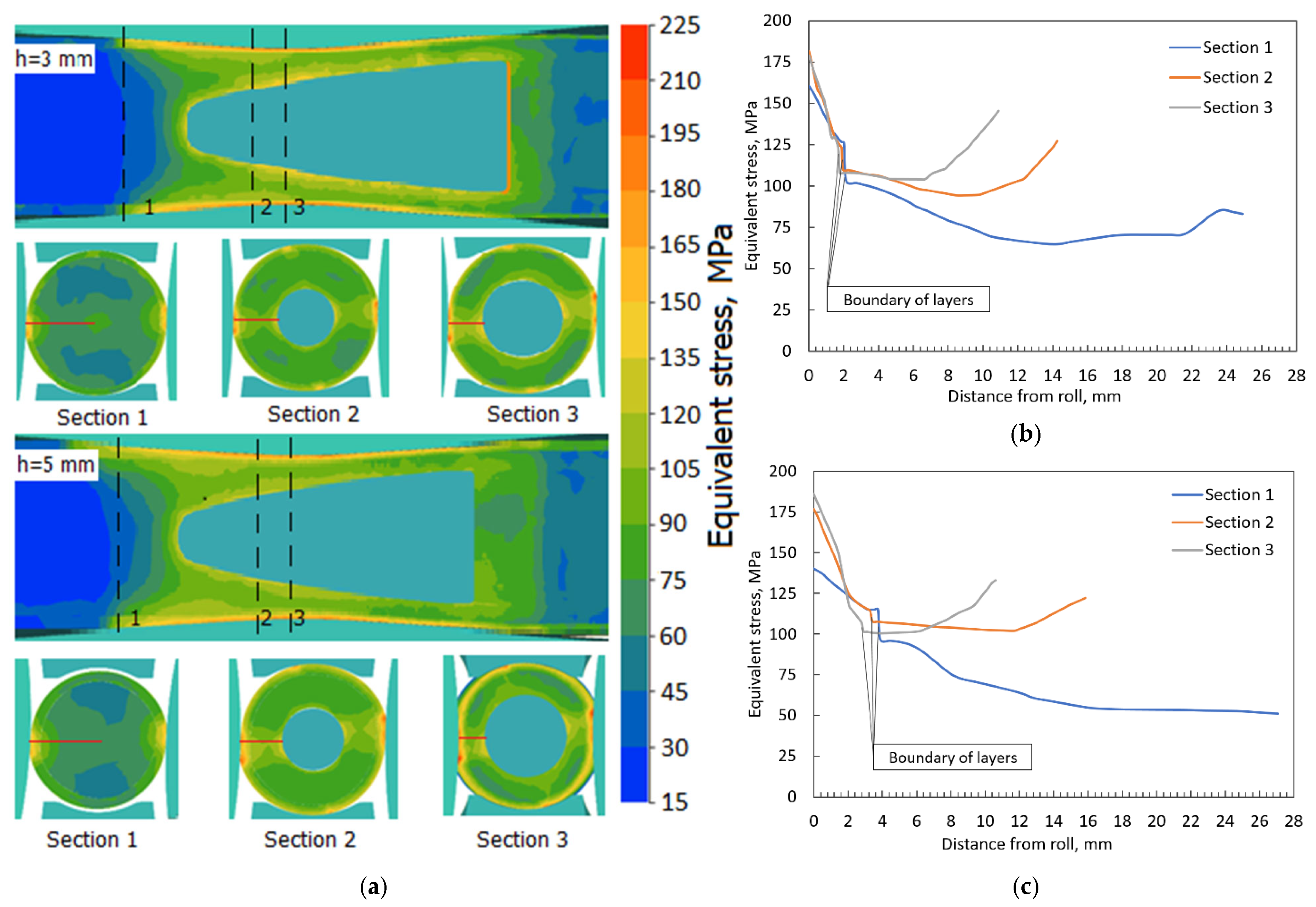
The equivalent stress field (Figure 6a) shows that the highest values of = 210–225 MPa are localized within the cladding layer in the roll gorge zone (Section 2 and Section 3), both when piercing products with h = 3 mm and with h = 5 mm. The distribution of equivalent stress is relatively uniform throughout the deformation zone and across the pipe wall thickness, with only minor peaks in the roll contact area and a slight increase in the area of the mandrel contact, which indicates the uniformity of strain distribution, the correctness of the tool calibration and the stability of the piercing process. Figure 6b,c show the curves of change in equivalent stress across sections of workpiece in the direction from the roll (see red lines in Figure 6a). It can be seen that the sharp decrease in stresses in the cladding layer occurs in the direction away from the contact surface with the roll. Then the stress drop ranging from 5 to 20 MPa is observed at the interlayer boundary. For Section 1, where deformation begins, the equivalent stress gradually decreases toward the workpiece axis. Further, in Section 2 and Section 3, where in addition to the roll, the mandrel acts on the axial zone, the equivalent stress in the base layer first decreases and then increases by 30–40 MPa toward the contact surface with the mandrel. Accordingly, heat generation during the piercing process begins intensively in Section 2 and Section 3.
Figure 6.
(a) Distribution fields of equivalent stress in deformation zone during screw piercing and curves of change in equivalent stress across section of workpiece (red line) with different initial CL: (b) h = 3 mm; (c) h = 5 mm.
The conversion of deformation energy into heat can be determined as follows:
Accordingly, the higher the equivalent stress and strain rate values, the greater the deformation heating. This also indicates that the workpiece temperature will increase more rapidly in the cladding layer. The identical change in the temperature of the workpiece during screw rolling was demonstrated during FEM simulation and experimental piercing and rolling of superaustenitic stainless steel (SASS) AISI 904L by Murillo-Marrodán at al [39]. During piercing, the heating of the metal layers close to the surface reached the values of 80–100 °C, while on the contact surface with the mandrel, the temperature dropped by 40–50 °C.
As can be seen, during the piercing (Figure 7a), the compressive stress fields ranging from −80 to −150 MPa are dominantly generated across the entire metal–tool contact area in the cladding layer. The tensile stresses are present in the gaps between rolls and guides, but their values do not exceed 10 MPa. As can be seen in Figure 7b,c, tensile stresses are almost completely absent in Section 1 due to the supporting effect created by the mandrel in the axial zone of the workpiece. To a greater extent this applies to thickness of CL h = 3 mm, where contact with the rolls occurs closer to the mandrel nose. It is well known that the Mannesmann effect is observed during screw piercing [40,41,42], which can result in axial fracture of the metal. Incorrect setting of the deformation modes can lead to defects in the pierced pipes. Therefore, the piercing process should be designed to avoid significant tensile stresses in the section from Section 1 to the mandrel nose.
Figure 7.
(a) Distribution fields of mean stress in deformation zone during screw piercing and curves of change in mean stress across section of workpiece (red line) with different initial CL: (b) h = 3 mm; (c) h = 5 mm.
For Section 2 and Section 3, the mean stresses vary from −120 to −100 MPa in the cladding layer and further decrease in their level to 0 (for a 5 mm layer). Insignificant positive values of no more than 30 MPa are observed on the contact spherical surface of the mandrel (for a 3 mm layer) due to deformation in the longitudinal direction.
Figure 8 illustrates the equivalent strain distribution across the deformation zone. High values of equivalent strain are indicative of severe deformation and refinement of the metal structure. Both cladding thickness configurations exhibit similar deformation patterns. According to simulation results, during the piercing, the equivalent strain field is initially heterogeneous, with higher strain values observed at the mandrel contact surface. However, after exiting the deformation zone, strain distribution becomes close to uniform through the wall thickness due to the deformation effect from the roll in the zone after roll gorge. For h = 5 mm, the absolute equivalent strain values are slightly higher (6–8.5) compared to h = 3 mm (4–7.8), which is attributed to the higher elongation ratio and longer deformation zone. It can also be noted that for CL h = 3 mm, the equivalent strain distribution in the base material is U-shaped with minimum values at approximately 0.5 wall thicknesses. This can be explained by the shorter deformation zone length for the pipe workpiece with a thinner CL. In general, the obtained values of , in combination with the stress state, where compressive stresses predominate, and equivalent stresses are distributed uniformly along the length of the deformation zone, indicate a favorable deformation mode that promotes intensive processing of the workpiece structure without the risk of defect formation.
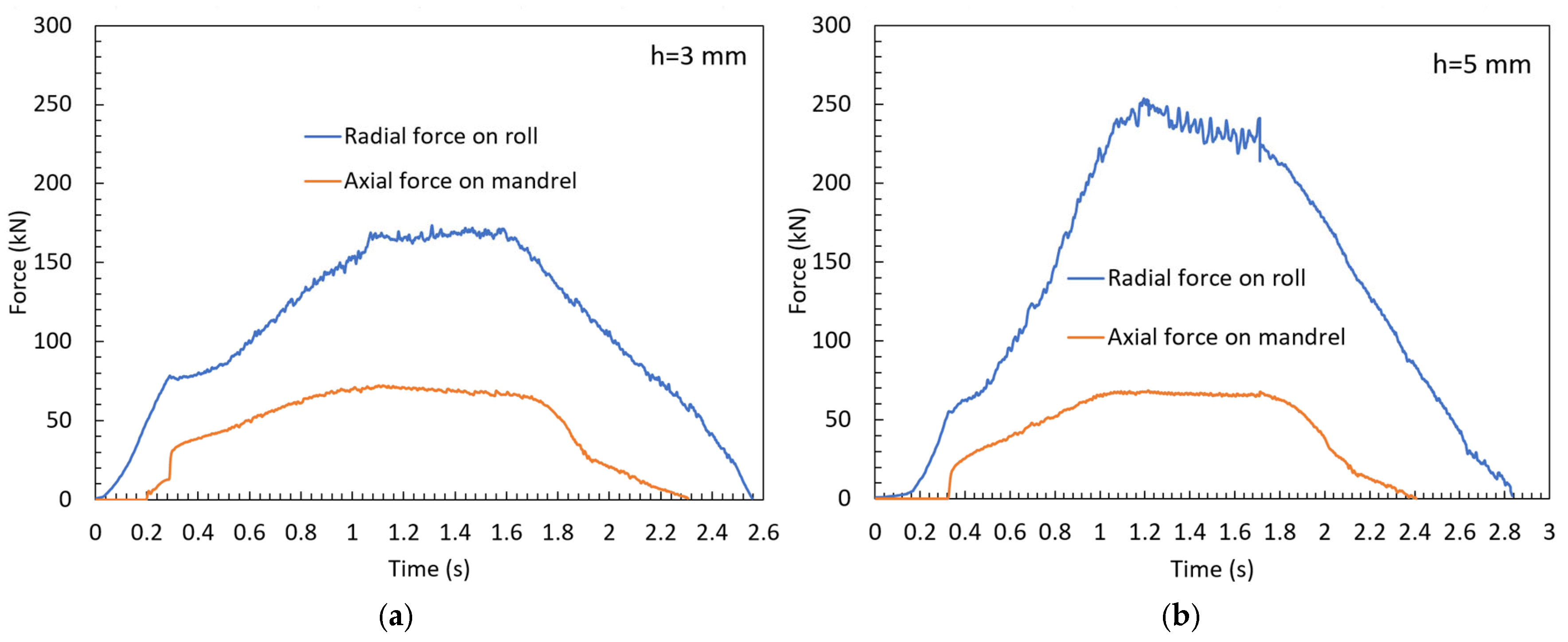
Another important parameter that determines the correctness of the design of the technology and deformation parameters is the forces acting on the tool. Figure 9 presents curves of the radial force on the roll (Pr) and axial force on the mandrel (Pm) vs. time, and Table 5 summarizes the average values of the force during the stable state, and their ratio (Pm/Pr). The force curves show no sharp fluctuations in the stages of primary roll gripping (initial contact with the rolls) and secondary roll gripping (initial contact with the mandrel), or during the stable piercing phase and release of the deformation zone. Slight fluctuations in the curves can be attributed to the inevitable fluctuation in the number of nodes at the contact during the rebuilding of the finite element mesh during the simulation process. During the secondary roll gripping phase, a sharp increase in the force on the mandrel is observed, which can be explained by the instantaneous formation of a contact area with the mandrel after passing the guide hole. As the deformation zone is released, a characteristic change in the slope of curve of the force on mandrel occurred due to a change in the balance of frictional forces at the contact with the tool. The obtained curves of forces are characteristic of the piercing process and do not differ in the nature of the change from similar ones when piercing a solid workpiece made of a single material.
Figure 9.
Curves of radial force on roll and axial force on mandrel during screw piercing of workpiece with different initial CL: (a) h = 3 mm; (b) h = 5 mm.
Table 5.
Average radial force on roll and axial force on mandrel during screw piercing.
As the cladding thickness increases from 3 mm to 5 mm, the average roll force rises from 165.5 kN to 236.3 kN (~30%), due to increased reduction, and, accordingly, there is an increase in the area of the contact surface of the workpiece with the roll. Conversely, the mandrel force decreases by approximately 5 kN (7%), a relatively insignificant change.
The ratio of mandrel to roll force ranges from 28% (0.28) to 43% (0.43). During screw piercing operations, the mandrel performs under the most challenging temperature and force conditions. Therefore, the ability to increase the reduction without significantly increasing the mandrel force enables more efficient piercing modes, such as increasing pipe length or more intensive deformation processing.
3.2. Screw Rolling
Measurements of geometric dimensions and analysis of layer ratio changes were also conducted for pipes after simulation of screw rolling process (Table 6). With identical rolling parameter settings and regardless of the initial thickness of the cladding layer, practically identical dimensions of the outer diameter of the pipe (50–50.5 mm) with a deviation of no more than ±0.12 mm, and wall thickness (7.1–7.4 mm) with a deviation of ±0.03 mm, were obtained. The final outer diameter was observed to be approximately 2 mm smaller than the calculated value (in contrast to the piercing process), which is attributed to the absence of a rolling angle of inclination on the mandrel after the roll gorge. This reduces radial metal flow and the increase in diameter at the roll exit cone. Therefore, the selected rolling settings and tool calibration ensure a sufficiently accurate cross-section of the pipe with geometric dimensions close to the calculated ones.
Table 6.
Geometric dimensions of pipes after rolling at different initial cladding thicknesses.
The cladding layer reduction during rolling is approximately 55–56%, independent of its initial thickness. The layer ratio of cladding to base material decreases from 0.18 to 0.14 for h = 2 mm, and from 0.27 to 0.22 for h = 3 mm, respectively.
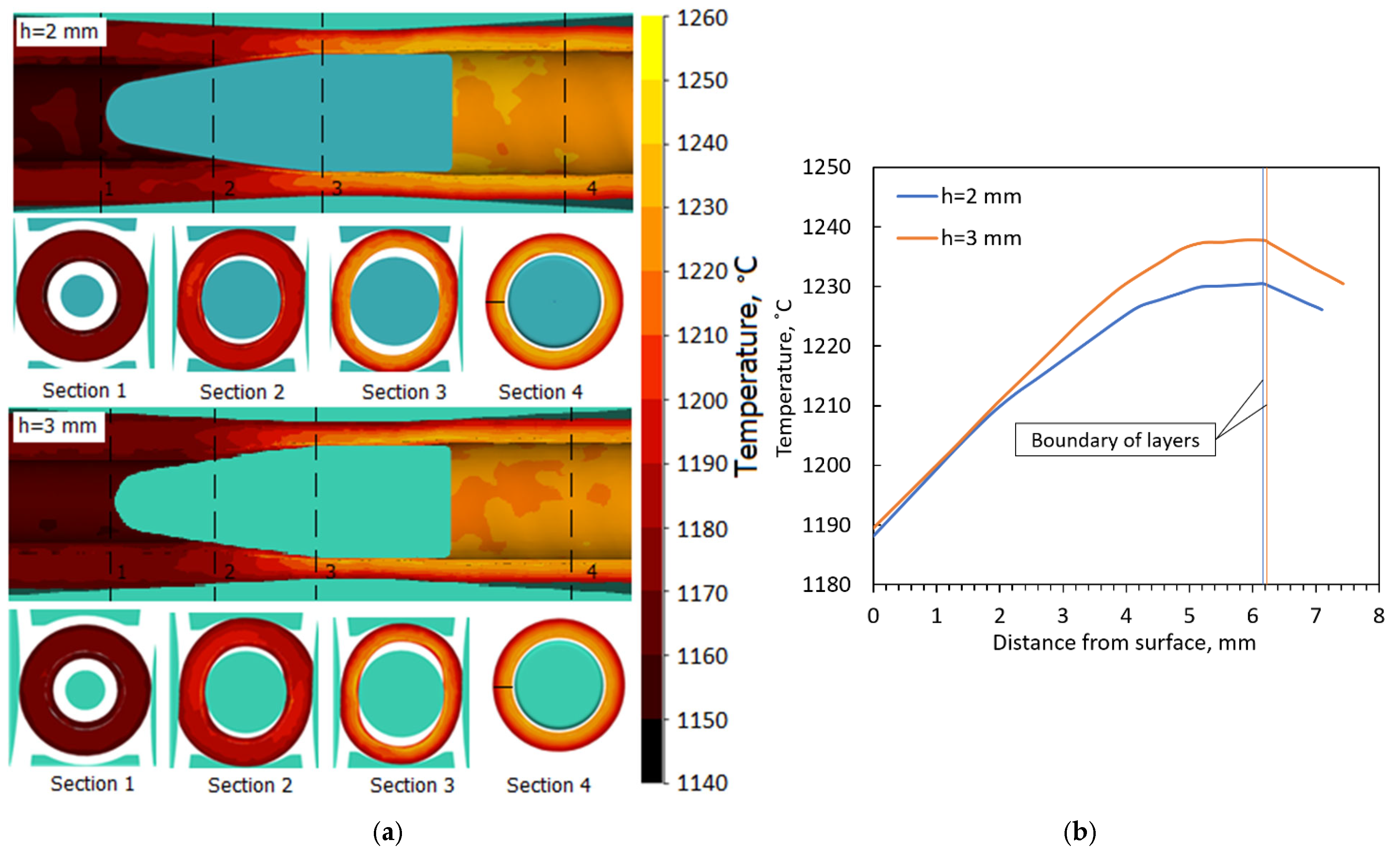
Figure 10 illustrates the temperature field distribution in the pipe during screw rolling, shown in both longitudinal and transverse sections of the deformation zone. For the two variants of the CL thickness, the nature of the temperature change during the deformation process was identical. In the area from the beginning of contact of the metal with the mandrel, a zone with an increase in temperature begins to form, associated with the release of heat from deformation and sliding. Moreover, the zone with a higher temperature is observed closer to the inner surface of the pipe, which is explained by two main reasons: firstly, the lower thermal conductivity of the corrosion-resistant steel of CL and, secondly, the smaller area of contact between the metal and the tool. At Section 2 and Section 3 (Figure 10a) it can be seen that near the roll gorge the ovalization was formed, resulting in contact between the pipe and mandrel only in the section of rolls. At the exit from the rolls (Section 4), a uniform annular profile of the pipe is formed with a small gap between the mandrel and the inner surface of the pipe.
Figure 10b shows the through-thickness temperature gradient from the outer to the inner pipe surface at Section 4. From the outer surface to a distance of approximately 2 mm, the temperature remains nearly constant at 1190–1210 °C for both thicknesses of CL. The temperature of the pipe with a thickness of h = 3 mm increases more rapidly due to greater deformation across the wall thickness, reaching a maximum of 1240 °C at the boundary of layers. For the inner cladding layer, the temperature decreases uniformly from the maximum by approximately 5–10 °C. Thus, during the rolling process, intense deformation heating also occurs, reaching 50 °C at the layer boundary. The outer surface of the pipe has the minimum temperature, and the difference between the inner and outer surfaces is approximately 40 °C.
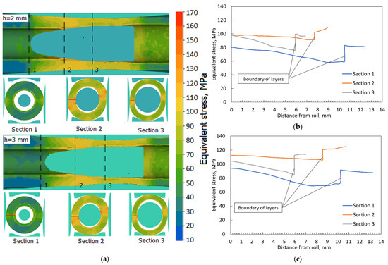
When screw rolling, it is also important to analyze the stress–strain state, which allows predicting the force conditions of deformation, the failure probability, and the nonuniformity of strain distribution and to optimize the technological process. Figure 11 presents fields of equivalent stress along the longitudinal and transverse sections of the deformation zone. The patterns of their distribution across the pipe volume are identical for the two CL thicknesses considered. Stresses are localized along the length of metal contact with the rolls. The highest equivalent stresses develop in the spherical section of the mandrel and reach peak values of 150–160 MPa in Section 2 along the line connecting the metal entry points with the gap between the roll and the mandrel (Figure 11a). In the area where the pipe wall thickness is rolled, the stresses in the inner CL are higher, despite the higher temperature of this layer (see Figure 10).
Figure 11.
(a) Distribution fields of equivalent stress in deformation zone during screw rolling and curves of change in equivalent stress across section of pipe workpiece (red line) with different initial CL: (b) h = 2 mm; (c) h = 3 mm.
The curves of change in equivalent stress across sections of pipe workpiece (see red lines in Figure 11a) show that during the rolling of a pipe workpiece, the equivalent stresses are distributed fairly uniformly across the entire layer thickness, for both the base layer and the cladding layer. However, the difference in the rheological properties of the materials results in stress differences of up to 20–30 MPa at the boundary, which represents up to 30% of the maximum stress level in the inner cladding layer.
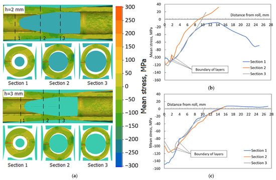
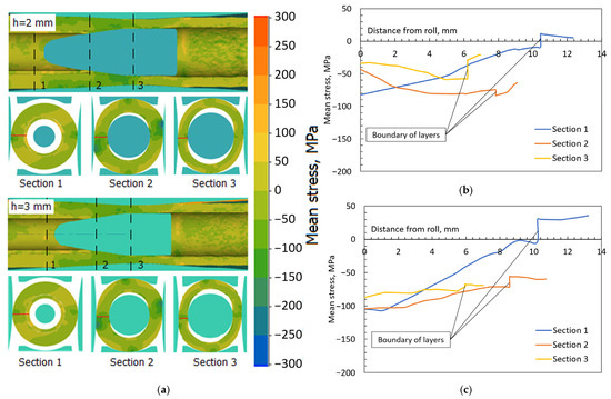
According to the analysis of the mean stress fields, during screw rolling, compressive stress fields are formed for the entire area of contact between the metal and the tool, which range from −50 to −150 MPa with the exception of the cladding layer in Section 1 (Figure 12a). In this case, the positive mean stresses are caused by a slight elongation of the pipe workpiece in the primary roll gripping area. From the point of view of the destruction, these positive mean stresses cannot result in the debonding of layers due to their insignificant values and the absence of deformation impact from the mandrel.
Figure 12.
(a) Distribution fields of mean stress in deformation zone during screw rolling and curves of change in mean stress across section of pipe workpiece (red line) with different initial CL: (b) h = 2 mm; (c) h = 3 mm.
In Section 2 and Section 3, where significant ovalization is formed, low positive (tensile) stresses (20–30 MPa) can be observed on the outer surface between the rolls and guides. However, these stresses are low in magnitude and located outside the interface zone of layers, which indicates a low probability of delamination.
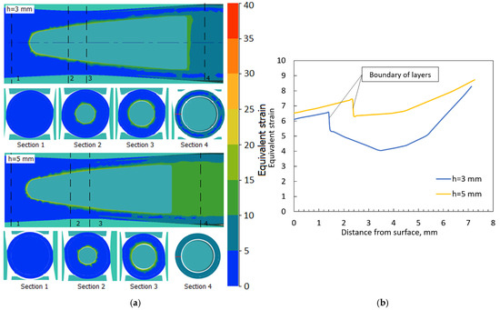
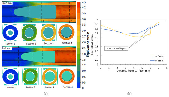
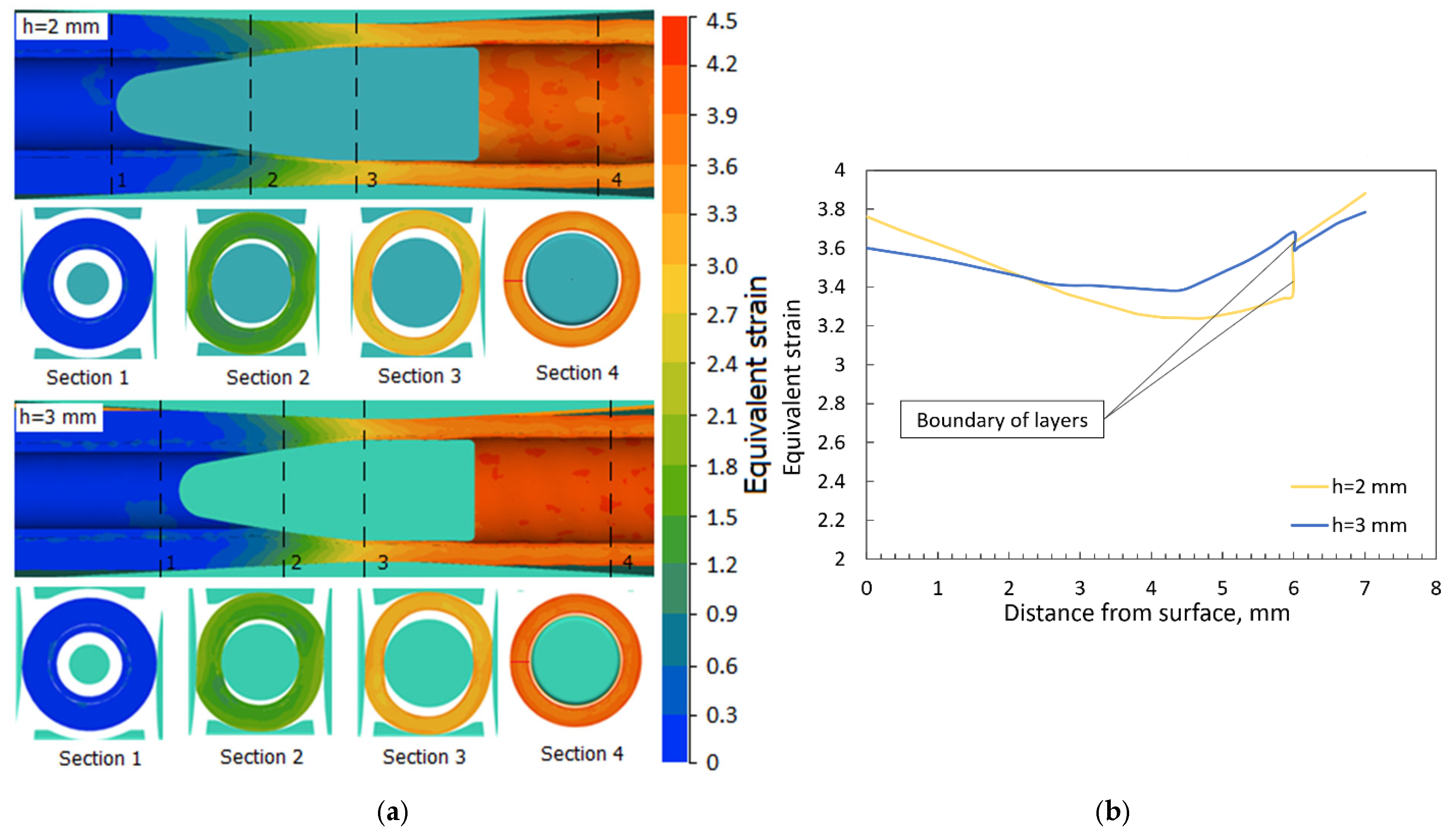
Figure 13 shows the distribution of equivalent strain throughout the sections of the deformation zone. As noted above, high values of this parameter are favorable for deformation processing and strengthening of the metal. However, under conditions of significant tensile stresses, it shows the probability of failure [43,44]. During screw rolling, the value of equivalent strain increases uniformly, reaching values of 3.3–3.8 for a thickness of CL = 2 mm and 3.5–3.8 for a thickness of CL = 3 mm at the exit from the rolls. It is interesting to note that for CL h = 2 mm, the equivalent strain of the base material at the boundary of layers is somewhat lower, which is due to the larger outer initial diameter of the pipe workpiece and, as a consequence, the shorter length of contact with the mandrel in the deformation zone. The obtained values of equivalent strains are quite high; however, as shown above, most of the metal volume in the deformation zone experiences compressive stress, which indicates uniform deformation of the layers without destruction.
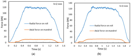
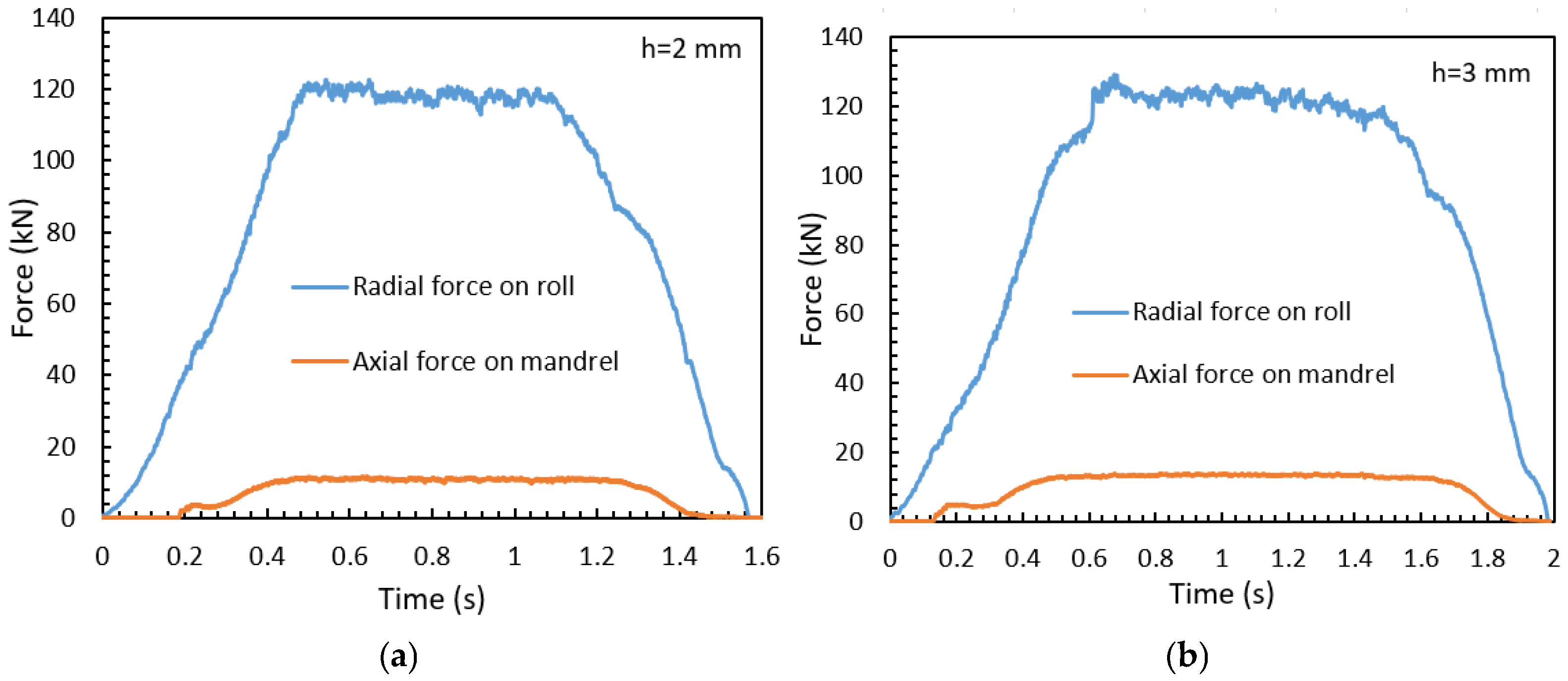
Figure 14 presents the curves of the radial force on the rolls (Pᵣ) and axial force on the mandrel (Pm) vs. time, and Table 7 summarizes the average values of the force during the stable state of screw rolling, and their ratio (Pm/Pr). Similar to the piercing process, during screw rolling, several stages can be observed such as a uniform increase in the force on the tool during the filling of the deformation zone, a steady-state stage, and a uniform decrease during the release of material from the deformation zone. The absence of sharp fluctuations and drops in force indicates correctness of tool setup and rolling mode selection.
Figure 14.
Curves of radial force on roll and axial force on mandrel during screw rolling of pipe workpiece with different initial CL: (a) h = 2 mm; (b) h = 3 mm.
Table 7.
Average radial force on roll and axial force on mandrel during screw rolling.
Increasing the cladding thickness from 2 mm to 3 mm results in a modest increase in average roll force from 115.3 kN to 121.3 kN (approximately 5%). However, mandrel force increases by 3 kN or 20%, due to the greater volume of high-deformation-resistance cladding material in contact with the mandrel. The ratio of the forces on the mandrel and on the roll is approximately 9% (0.09) to 11% (0.11), which is consistent with other experimental data [27,45,46,47].
In industrial practice, the maximum forces on the roll and the mandrel are determined by the maximum diameter of the workpiece used on a specific mill, the roll diameter, and the specific deformation conditions. In this study, for the equipment in question, the maximum workpiece diameter that can be used is 120 mm, and the roll diameter in the gorge is 430 mm. For those parameters, the maximum allowable radial force on the roll is 1000 kN, and the axial force on the mandrel is up to 300 kN. For the workpieces used in this study (see Table 2 and Table 3), the forces obtained are significantly lower than the allowable values for both the solid workpiece piercing process and pipe rolling.
To analyze the obtained data for the piercing and rolling processes, it can be concluded that the greatest increase in force is observed for the tool that contacts the cladding layer with a higher resistance to deformation. According to comparison, with correctly set equipment parameters and tool calibration, the thickness of the cladding layer does not have a significant impact on the quality of the bond. For the screw rolling process, the choice of the initial cladding layer thickness primarily depends on the required final layer thickness after deformation and the selected reduction.
The main results obtained from the FEM simulation are summarized for convenience in Table 8, which includes the pipe geometric accuracy, the reduction in the CL thickness, the change in temperature, the stress–strain state, and the force on the tool. The summarized results demonstrated that both screw piercing and screw rolling provide stable deformation conditions, accurate pipe geometry, a favorable stress–strain state and an acceptable tool load. These data provide a solid foundation for subsequent experimental testing and industrial implementation of the proposed technology for the production of bimetallic seamless pipes.
Table 8.
Summary of the FEM simulation results for screw piercing and screw rolling of bimetallic pipes.
To verify the data obtained during the simulation, a series of experimental tests are planned under conditions as close as possible to those specified during the piercing and rolling simulation. For the experiment, workpieces of different types from selected materials obtained by explosive welding, with different CL thicknesses and locations (internal/external) will be used. The screw piercing and rolling of workpieces will be implemented on a two-high screw rolling mill with the recording of the force parameters. The resulting bimetallic pipes will be measured for pipe geometry, CL thickness, and joint quality, and compared with simulation data. The microstructure and hardness of the layers, including the joint area, will be examined to analyze the impact of temperature and deformation conditions.
4. Conclusions
This study investigates the temperature evolution and stress–strain state of bimetallic pipes with varying cladding layer thicknesses during screw piercing and screw rolling processes as novel production methods of bimetallic products using FEM simulation. Based on the simulation results, the following conclusions can be drawn:
- The analysis of shape change showed that the pipe geometry obtained from the simulation results corresponds to the calculated values, indicating that the tool calibration and deformation zone settings were correctly selected. Deviations in diameter and wall thickness do not exceed the permissible values for hot-rolled seamless pipes.
- Intensive deformation heating was observed at the interface of the cladding and base layers, with a temperature increase of 50–60 °C in both the piercing and rolling processes due to the differences in resistance to deformation and thermal conductivity of the layer materials. It should be considered when designing heating and deformation modes of bimetallic pipes.
- The obtained equivalent strain values, combined with the stress state, where compressive stresses predominate, indicate a favorable deformation mode that facilitates intensive processing of the workpiece structure without the risk of defect formation during both piercing and rolling.
- In the case of rolling, the initial cladding thickness should be selected based on the required final thickness and the chosen reduction due to the forces on the roll and mandrel being significantly influenced by the deformation of the cladding layer. In the piercing process of solid workpieces, the mandrel force is practically independent of the cladding layer thickness, providing an opportunity to implement more efficient piercing modes, including increased pipe length or more intensive deformation processing.
- The obtained data can serve as a methodology that lays the groundwork for future experimental verification, including the use of these results to pilot the technology of screw piercing and rolling of bimetallic pipes with a cladding layer made of corrosion-resistant steel and comparison of the obtained experimental results with the model.
Author Contributions
Conceptualization, T.K., A.B. and Y.G.; data curation, T.K. and Y.G.; formal analysis, A.K. and I.S.; investigation, A.B., Y.G. and A.K.; methodology, Y.G. and T.K.; supervision, T.K. and Y.G.; validation, A.B., A.K. and Y.G.; visualization, A.K., T.K. and I.S.; writing—original draft, T.K., A.B. and Y.G.; writing—review and editing, T.K. and Y.G.; funding acquisition, A.B. All authors have read and agreed to the published version of the manuscript.
Funding
This research was funded by the Russian Science Foundation Grant No. 25-79-00041, https://rscf.ru/project/25-79-00041/ (accessed on 1 June 2026).
Data Availability Statement
All data that support the findings of this study are included within the article.
Conflicts of Interest
The authors declare no conflicts of interest.
References
- Yesuvadian, R.A.; Keerthiprasad, K.S. A Review on Casting and Testing of Bimetals. Int. J. Appl. Eng. Res. 2023, 18, 278–291. [Google Scholar] [CrossRef] [Scilit]
- Wang, Y.; Gao, Y.; Li, Y. Review of preparation and application of copper–steel bimetal composites. Emerg. Mater. Res. 2019, 8, 538–551. [Google Scholar] [CrossRef] [Scilit]
- Mróz, S.; Mola, R.; Szota, P.; Stefanik, A. Microstructure and properties of 1050A/AZ31 bimetallic bars produced by explosive cladding and subsequent groove rolling process. Arch. Civ. Mech. Eng. 2020, 20, 77. [Google Scholar] [CrossRef] [Scilit]
- Zixuan, L.; Shahed, R.; Tao, W.; Han, J.; Shu, X.; Pater, Z.; Huang, Q. Recent advances and trends in roll bonding process and bonding model: A review. Chin. J. Aeronaut. 2023, 36, 36–74. [Google Scholar] [CrossRef] [Scilit]
- Wang, D.; Sun, X.; Jiang, Y.; Chang, X.; Xin, Y. Review on the application of stainless-clad bimetallic steel in the marine environment. Anti-Corros. Methods Mater. 2024, 71, 132–142. [Google Scholar] [CrossRef] [Scilit]
- Su, H.; Fu, A.; Li, W.; Yin, C. Application of the corrosion resistant alloy/carbon steel bimetal pipes in oil and gas field development. In Proceedings of the AMPP Annual Conference + Expo, Denver, CO, USA, 19–23 March 2023; p. 3546. [Google Scholar] [CrossRef] [Scilit]
- Bogatov, N.A.; Bogatov, A.; Salikhyanov, D.R. New engineering solutions in the production of laminated composite pipes for the oil industry. In Progress in Materials Science and Engineering; Innovation and Discovery in Russian Science and Engineering; Brebbia, C., Connor, J., Eds.; Springer: Cham, Switzerland, 2018; pp. 163–169. [Google Scholar] [CrossRef] [Scilit]
- Li, Y.; Jin, Z.; Ren, T.; Zhuang, W.; Zhang, W.; Xia, Y.; Huang, X. Mechanical properties of bimetallic composite pipes in deep sea. Proc. Inst. Mech. Eng. J. J. Eng. Tribol. 2025, 239, 1603–1611. [Google Scholar] [CrossRef] [Scilit]
- Davydov, A.D.; Kolnyshenko, V.V.; Kurakin, M.K. Evaluation of the effectiveness of the cladding layer material of a bimetallic pipeline for transporting wet gas. Metallurgist 2025, 68, 1819–1827. [Google Scholar] [CrossRef] [Scilit]
- Bogatov, N.A.; Bogatov, A.A.; Salikhyanov, D.R. Expansion of a pair of dissimilar metal shells in lined-pipe production. Steel Transl. 2016, 46, 453–457. [Google Scholar] [CrossRef] [Scilit]
- Nikitin, K.N.; Osadchii, V.Y.; Saf’yanov, A.V.; Kolikov, A.P.; Bubnov, K.E. Production of seamless bimetallic pipe for the nuclear industry. Steel Transl. 2017, 47, 491–496. [Google Scholar] [CrossRef] [Scilit]
- Cho, J.M.; Kim, B.S.; Moon, H.K.; Lee, M.C.; Joun, M.S. Comparative study on Mannesmann roll piercing process between Diescher’s guiding disk and Stiefel’s Guiding Shoe. Inst. Met. Res. 2013, 1532, 843–849. [Google Scholar] [CrossRef] [Scilit]
- Golovko, O.; Bieliaiev, S.M.; Nürnberger, F.; Danchenko, V.M. Extrusion of the bimetallic aluminium-magnesium rods and tubes. Forsch. Ingenieurwes 2015, 79, 17–27. [Google Scholar] [CrossRef] [Scilit]
- Goncharuk, A.V.; Fadeev, V.A.; Kadach, M.V. Seamless pipes manufacturing process improvement using mandreling. Solid State Phenom. 2021, 316, 402–407. [Google Scholar] [CrossRef] [Scilit]
- Romantsev, B.A.; Goncharuk, A.V.; Davydova, E.A.; Lube, I.I.; Stoppe, E.V. Improved calculation of the deformational and rate parameters in pipe rolling on a continuous mill. Steel Transl. 2009, 39, 197–199. [Google Scholar] [CrossRef] [Scilit]
- Aghajani Derazkola, H.; García, E.; Murillo-Marrodan, A. Effects of skew rolling piercing process friction coefficient on tube twisting, strain rate and forming velocity. J. Mater. Res. Technol. 2023, 25, 7254–7272. [Google Scholar] [CrossRef] [Scilit]
- Pater, Z.; Wójcik, L.; Walczuk, P. Comparative Analysis of Tube Piercing Processes in the Two-Roll and Three-Roll Mills. Adv. Sci. Technol. Res. J. 2019, 13, 37–45. [Google Scholar] [CrossRef] [Scilit] [PubMed]
- Rotenberg, Z.Y.; Budnikov, A.S.; Dudyriev, M.D. Application of computer modeling for the evaluation of performance of a new method of cross-screw rolling. Metallurgist 2025, 69, 158–165. [Google Scholar] [CrossRef] [Scilit]
- Ye, C.; Shu, X.; Cen, Z.; Li, Z.; Xu, H.; Wang, Y. Effect of rolling parameters on hierarchical microstructure and mechanical properties during rotary tube piercing of 30NiCrMoV12 martensitic steel tubes. Mater. Charact. 2025, 228, 115339. [Google Scholar] [CrossRef] [Scilit]
- Kin, T.; Gamin, Y.; Galkin, S.; Skugorev, A. Numerical simulation of workpiece temperature field during radial shear rolling of biomedical Co-Cr-Mo alloy. Model. Simul. Mater. Sci. Eng. 2023, 31, 045012. [Google Scholar] [CrossRef] [Scilit]
- Mahmoud Alhaj Ali, A.; Khakimova, A.; Gamin, Y.; Kin, T.; Letyagin, N.; Demin, D. Numerical analysis and experimental verification of radial shear rolling of titanium alloy. Modelling 2025, 6, 93. [Google Scholar] [CrossRef] [Scilit]
- Tomczak, J.; Bulzak, T.; Pater, Z.; Wójcik, Ł.; Kusiak, T. Skew rolling of bimetallic rods. Materials 2021, 14, 18. [Google Scholar] [CrossRef] [Scilit] [PubMed]
- Kusiak, T.; Tomczak, J.; Wójcik, J. The influence of the parameters of the skew rolling process for bimetallic elements on the mechanical properties and structure of materials. Materials 2024, 17, 4558. [Google Scholar] [CrossRef] [Scilit] [PubMed]
- Szota, P.; Stefanik, A.; Dyja, H. Analysis of bimetallic bar rolling process in a three-skew rolling mill. Arch. Metall. Mater. 2009, 54, 607–615. [Google Scholar]
- Sawicki, S.; Szota, P.; Dyja, H. Analysis of the bimetallic bars rolling during a skew rolling. Arch. Metall. Mater. 2008, 31, 53–56. [Google Scholar]
- Zhu, L.; Sun, C.; Zhou, J.; Baoyu, W.; Long, M.; Xuan, W.; Ning, L.; Jialong, L. The deformation law and interfacial bonding mechanism of bimetallic hollow shafts cross-wedge rolling with mandrel. Arch. Civ. Mech. Eng. 2025, 25, 178. [Google Scholar] [CrossRef] [Scilit]
- Hu, J.; Ma, J.; Hao, Y.; Zhang, G.; Zhenqi, Z.; Pei, Y. Optimization of skew rolling piercing process for bimetallic composite pipes based on numerical simulation and intelligent algorithm fusion. J. Mater. Eng. Perform. 2026, 35, 7599–7611. [Google Scholar] [CrossRef] [Scilit]
- Dong, Z.; Xu, Z.; Wang, W.; Bi, Z.; Zhang, J. Numerical simulation and experimental confirmation of a bimetallic pipe forming process. Materials 2020, 13, 3561. [Google Scholar] [CrossRef] [Scilit] [PubMed]
- Malakhov, A.; Saikov, I.; Denisov, I.; Cherezov, N. Study of the welding zone in double-layer pipe billets produced by explosion welding. Key Eng. Mater. 2020, 839, 119–123. [Google Scholar] [CrossRef] [Scilit]
- Malakhov, A.; Niyozbekov, N.; Denisov, I.; Saikov, I.; Shakhray, D.; Volchenko, E. Study of Structure Formation in Multilayer Composite Material AA1070-AlMg6-AA1070-Titanium (VT1-0)-08Cr18Ni10Ti Steel after Explosive Welding and Heat Treatment. J. Manuf. Mater. Process. 2024, 8, 188. [Google Scholar] [CrossRef] [Scilit]
- Kin, T.Y.; Khakimova, A.N.; Budnikov, A.S.; Solovev, I.S.; Saikov, I.V.; Malakhov, A.Y. Study of screw rolling process for production of bimetallic pipes: Simulation and experimental testing. Metallurg 2026, 3, 85–91. (In Russian) [Google Scholar]
- Jong-Youn, S.; Ki-Yong, L.; Gwang-Yong, S.; Chang-Hwan, C.; Do-Sik, S. Mechanical and Thermal Properties of the High Thermal Conductivity Steel (HTCS) Additively Manufactured via Powder-Fed Direct Energy Deposition. Micromachines 2023, 14, 872. [Google Scholar] [CrossRef] [Scilit] [PubMed]
- Grzesik, W.; Niestony, P. FEM–based thermal modelling of the cutting process using power law-temperature dependent concept. Arch. Mater. Sci. Eng. 2008, 29, 105–108. [Google Scholar]
- Timoshpolski, V.; Kabishov, S.; Kalinevich, E.; Vais, B. Analysis of the steels thermophysical characteristics with the pupose of application for solving of non-linear problems of heating theory. Litiyo I Metall. 2006, 2, 17–22. (In Russian) [Google Scholar]
- Aleshchenko, A.; Muntin, A.; Gamin, Y.; Yushchuk, V.; Zlobin, D. Application of the NUST MISIS pilot industrial equipment complex for physical modeling of seamless pipe production technology. Chernye Met. 2024, 11, 32–38. [Google Scholar] [CrossRef] [Scilit]
- Murillo-Marrodan, A.; Garcia, E.; Cortes, F. A Study of Friction Model Performance in a Skew Rolling Process Numerical Simulation. Int. J. Simul. Model. 2018, 17, 569–582. [Google Scholar] [CrossRef] [Scilit] [PubMed]
- Peng, Y.; Guo, S.; Liu, C.; Barella, S.; Liang, S.; Gruttadauria, A.; Mapelli, C. Dynamic recrystallization behavior of low-carbon steel during hot rolling process: Modeling and simulation. J. Mater. Res. Technol. 2022, 20, 1266–1290. [Google Scholar] [CrossRef] [Scilit]
- Poliak, I. Dynamic recrystallization control in hot rolling. Procedia Manuf. 2020, 50, 362–367. [Google Scholar] [CrossRef] [Scilit]
- Murillo-Marrodán, A.; Gamin, Y.; Kaputkina, L.; García, E.; Aleshchenko, A.; Derazkola, H.A.; Pashkov, A.; Belokon, E. Microstructural and Mechanical Analysis of Seamless Pipes Made of Superaustenitic Stainless Steel Using Cross-Roll Piercing and Elongation. J. Manuf. Mater. Process. 2023, 7, 185. [Google Scholar] [CrossRef] [Scilit]
- Zhang, Z.; Liu, D.; Man, T.; Li, N.; Yang, Y.; Pang, Y.; Wang, J. Numerical and experimental investigations on Mannesmann effect of nickel-based superalloy. Arch. Civ. Mech. Eng. 2022, 22, 133. [Google Scholar] [CrossRef] [Scilit]
- Joun, M.S.; Lee, J.; Cho, J.M.; Jeong, S.W.; Moon, H.K. Quantitative study on Mannesmann effect in roll piercing of hollow shaft. Procedia Eng. 2014, 81, 197–202. [Google Scholar] [CrossRef] [Scilit]
- Ghiotti, A.; Fanini, S.; Bruschi, S.; Bariani, P.F. Modelling of the Mannesmann effect. CIRP Ann. 2009, 58, 255–258. [Google Scholar] [CrossRef] [Scilit]
- Zhang, Z.; Liu, D.; Wang, J. Compression-shear fracture of nickel-based superalloy during rotary tube piercing. Eng. Fract. Mech. 2024, 295, 109777. [Google Scholar] [CrossRef] [Scilit]
- Tang, B.; Li, M.; Guo, N.; Li, Q.; Zhang, Z. Genetic effects of dynamic recrystallization on ductile fracture at elevated temperature for AA7075 alloy with various stress states: Modeling and simulation. Int. J. Mater. Form. 2023, 16, 9. [Google Scholar] [CrossRef] [Scilit]
- Aleshchenko, A.; Lakiza, V.; Romantsev, B.; Korol, V. Study of the resistance of plugs when piercing billets made of 20Kh13 steel on the MISIS-130D screw rolling mill. Chernye Met. 2023, 10, 70–74. [Google Scholar] [CrossRef] [Scilit]
- Kolikov, A.P.; Aleshchenko, A.S.; Fortunatov, A.N.; Kuznetsov, D.V. Improving the Methodology for Calculating Energy-Power Parameters when Piercing Blanks in Screw Rolling Mills. Steel Transl. 2024, 54, 336–342. [Google Scholar] [CrossRef] [Scilit]
- Goncharuk, A.V.; Gamin, Y.V.; Sharafanenko, I.K.; Aleshchenko, A.S. Piercing of a billet in a mill with guide disks. Russ. Metall. 2020, 13, 1637–1642. [Google Scholar] [CrossRef] [Scilit]

Disclaimer/Publisher’s Note: The statements, opinions and data contained in all publications are solely those of the individual author(s) and contributor(s) and not of MDPI and/or the editor(s). MDPI and/or the editor(s) disclaim responsibility for any injury to people or property resulting from any ideas, methods, instructions or products referred to in the content. |
© 2026 by the authors. Licensee MDPI, Basel, Switzerland. This article is an open access article distributed under the terms and conditions of the Creative Commons Attribution (CC BY) license.