


Abstract
The environmental pressure simulation facility is crucial to the development and testing of high-performance aeroengines. During environmental pressure simulation tests of aeroengines, a large amount of uncertain high-temperature and low-pressure gas is discharged into the pressure regulation system, resulting in significant disturbances and complex coupling among compressor unites, valves and the main pipe. To analyze the surge mechanism and support controller design, a control-oriented dynamic model of pressure regulation system is established. By considering the dominant pressure dynamics of the main pipe and the dynamic characteristics of compressors and regulating valves, the original complex system is simplified into a nonlinear model suitable for control analysis and safety-oriented design. Based on the developed model, the safe operation problem of compressor units is transformed into a constrained control problem. A cooperative sliding mode control (Co-SMC) method is then proposed to ensure that the compressor pressure ratio remains within a safe range while mitigating the impact of exhaust disturbances on the pressure regulation process. The proposed method enhances the robustness of pressure regulation system and the grid-connected efficiency of compressor units while guaranteeing the stability of closed-loop system. Comparative simulations under complex operating conditions demonstrate that the proposed method significantly improves both the safety level and control performance of pressure regulation system.
1. Introduction
The environmental pressure simulation test ground is critical for the development of advanced aircraft engines and propulsion systems [1]. Environmental pressure simulation testing is the most efficient and safe method for validating the aerodynamic compatibility of various components in aircraft engines. Some nations have developed relatively sophisticated environmental pressure simulation capabilities [2], such as the Arnold Engineering Development Center in the United States, with the Aerodynamic and Propulsion Test Facility (ASTF) being the largest and most advanced test ground globally [3]. The pressure regulation system is a core subsystem of environment pressure simulation facilities. It provides back pressure for environmental pressure testing by regulating the main pipe pressure and discharging high-temperature, low-pressure exhaust gases. Compressor units are core components of pressure regulation system. The pressure ratio of compressor is regulated by adjusting the main pipe pressure to ensure safe operation. This highlights the challenges of modeling and controlling such a complex, coupled system [4]. From a control perspective, the pressure regulation system can be regarded as a nonlinear large-scale system with multiple coupled subsystems and safety constraints. The coordinated operation of parallel compressor units therefore constitutes a typical cooperative control problem for complex industrial processes. The rapid development of advanced aeroengines significantly raises the requirements for the pressure regulation system. It also poses a potential threat to the safe operation of compressor units [5,6]. Therefore, it is important to apply appropriate process control methods.
To meet the testing requirements of high-performance aeroengine, the air source regulation unit needs to be replanned and expanded, with necessary adaptive transformation [7,8]. The pressure regulation system is mainly composed of numerous valves, compressors, and pipe networks. Regarding the valve control strategy, refs. [9,10] propose two optimization algorithms: high-precision position follow-up control and feedforward control, both of which are model-free methods based on PID control. However, these algorithms focus solely on modeling and controlling the pressure regulating valve, without considering the modeling of pressure regulation system. Refs. [11,12,13] present dynamic models for the compressor unit, including models for the compressor, pipe network, heat exchanger, and regulating valve. However, these models do not address the safety control concerns associated with multiple compressor units operating in parallel. Ref. [14] suggests a model predictive control (MPC) method to enhance the performance of anti-surge and process control. This approach aims to improve the control of surge problems in individual compressors. Additionally, ref. [15] proposes a feedforward anti-surge control strategy for parallel compressor units, which incorporates the multi-valve synchronization control strategy. The multi-valve synchronization method is designed to synchronize the adjustment of compressor units. However, this approach will lead to low resource utilization and poor fault tolerance. Therefore, safety control issues of compressor units in operation require more in-depth investigation to ensure the robustness and reliability of the overall system.
Cooperative and decentralized control strategies have been widely investigated for large-scale interconnected systems such as energy systems [16,17] and multi-UAV systems [18]. Cooperative control is a control process where multiple subsystems work together to achieve a common goal [19]. Centralized approaches may achieve optimal coordination but often suffer from scalability and reliability issues [20]. Decentralized and distributed schemes improve flexibility and fault tolerance through structured local coordination [17]. For instance, [21] adopts a decentralized MPC strategy in which each compressor is equipped with a local predictive controller. The local controllers explicitly incorporate the coupling among units, thereby achieving coordinated pressure regulation and surge constraint handling within a receding-horizon optimization framework. Although the decentralized MPC framework enables coordinated performance, its effectiveness relies on the availability of sufficiently accurate system models. The multi-valve synchronization mechanism is essentially still a single-valve control. Under this strategy, a surge occurring in a single compressor may require all units to be shut down and restarted, leading to significant time delay and increased energy consumption. To address these limitations, the cooperative regulation problem can be formulated as a decentralized optimization problem with global safety constraints. Specifically, a coordination objective is constructed based on tracking objectives and safety constraints. All local controllers cooperatively optimize this shared objective, thereby realizing coordination through a common safety-driven performance goal. However, the external disturbance of the cooperative method in the control process is easy to affect other collaborators. Learning-based control methods are explored for nonlinear systems subject to external disturbances [22,23]. However, their practical deployment in safety-critical industrial environments faces challenges in stability assurance and interpretability. Active disturbance rejection control (ADRC) treats unmodeled dynamics and uncertainties as total disturbances and compensates them via an extended state observer (ESO) [24]. Its disturbance-oriented philosophy demonstrates effectiveness in environmental pressure simulation facilities [25,26,27]. From a cooperative control perspective, embedding ADRC into a decentralized coordination framework enables stability-guaranteed local regulation while preserving system-level cooperative behavior. Compared with purely data-driven approaches, the proposed cooperative ADRC is decentralized, stability-oriented, and computationally efficient, making it suitable for safety-critical industrial applications.
To satisfy the test requirements of aeroengines, the pressure regulation system needs to supply pressure within a certain range to the rear compartment of aeroengines. As test conditions change, the impact on the pressure of main pipe may lead to a surge in the compressor, manifested as changes in the pressure ratio of compressor. Compressors are expensive, and the losses resulting from surge are incalculable. At present, there is still no suitable control strategy to confine the pressure ratio of compressor unit within a safe range. Pressure control is only achieved through the pressure regulating valve. This does not guarantee that each compressor operates within a safe range. There are several issues with main pipe pressure control, including long adjustment times, low precision, and weak anti-interference capabilities. Therefore, ensuring the safe operation of compressors while controlling the main pipe pressure is a key challenge for the pressure regulation system. To tackle with the aforementioned challenges, in this paper, a cooperative control method is proposed. The contributions are summarized as follows.
- Establish a control-oriented dynamic model of pressure regulation system by capturing the dominant pressure dynamics of main pipe and integrating compressor, cavity, and valve characteristics, which provides a modeling foundation for safety analysis and controller design.
- Develop a safety-oriented control framework, in which a decentralized penalty-based optimization update is implemented locally for each valve to enforce compressor safety constraints, while a cooperative SMC within the ADRC framework coordinates multi-valve actions without a centralized coordinator.
The outline of this paper is presented as follows. Section 2 provides an overview of working process of pressure regulation system and the mathematical model of its important components and establishes a control-oriented dynamic model. Section 3 designs a algorithm and demonstrates the convergence of the algorithm. Section 4 designs a cooperative controller for multiple units and proves the stability. Section 5 makes a comparative analysis of the current control effectiveness versus cooperative control strategy within a simulation environment. Finally, Section 6 concludes and outlines future research directions.
2. Mathematical Model of Pressure Regulation System
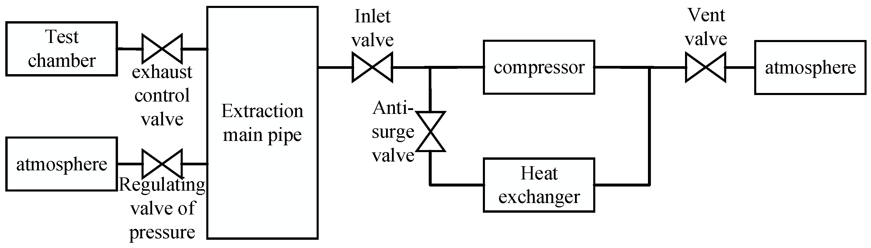
The pressure regulation system consists of multiple compressor units, various types of valves, heat exchangers, main pipe, and a complex network of pipes, as illustrated in Figure 1. To characterize the pressure dynamics and surge-related behavior during main pipe pressure control, a mathematical model of the entire pressure regulation system is established. The pressure regulation system is divided into generalized models such as the dynamic model of compressor, model of cavity characteristic, and model of regulating valve. Since the engine exhaust is cooled through cooling systems of multiple pipeline, the temperature is close to atmospheric temperature.
Figure 1.
Pressure regulation system diagram for multiple compressor units, illustrating the test chamber, extraction pipe, valves, compressor, and heat exchanger involved in the control process.
2.1. Dynamic Model of Compressors
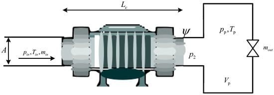
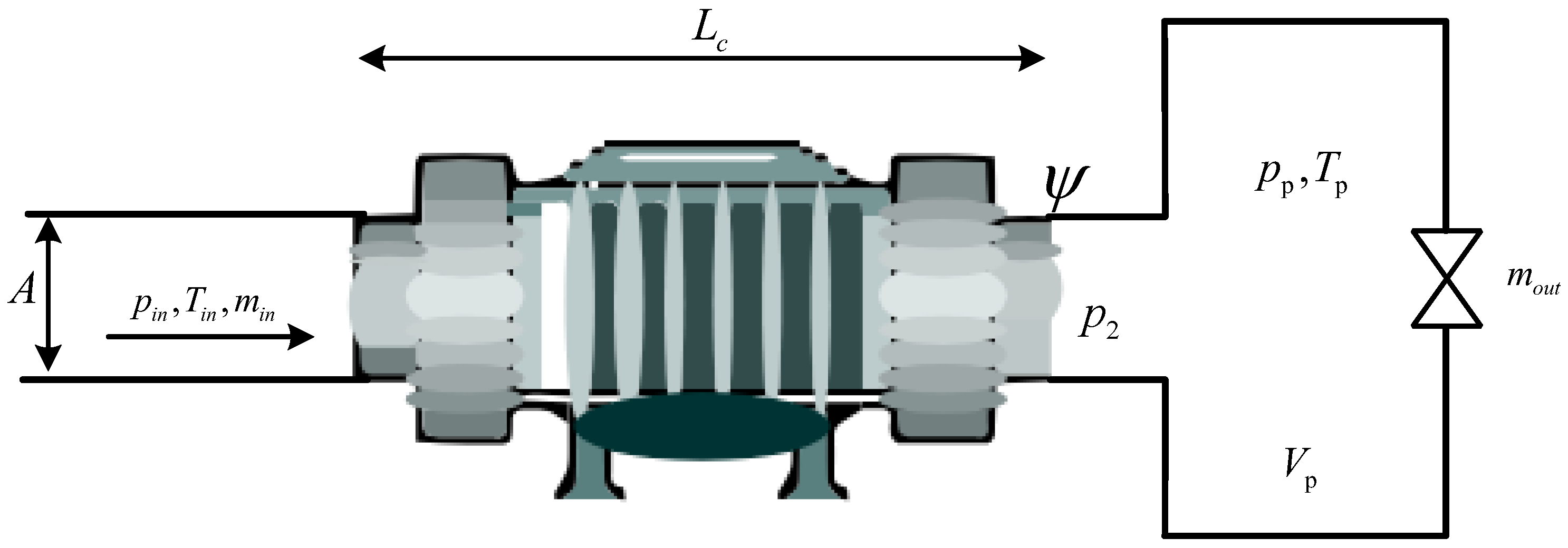
Centrifugal compressor is the core component of the pressure regulation system. Figure 2 depicts a schematic diagram of model of compressor. In this diagram, represents the inlet pressure, temperature, and mass flow rate of the compressor. is the dimensionless curve of the compressor, which represents the compressor boost process. The boost pressure can be obtained from the performance curve. and denote the average pressure and temperature of the equivalent cavity, respectively. represents the mass flow rate of the extracted gas. A is the equivalent flow area. is the equivalent flow distance, and is the equivalent cavity volume. The compressor model, according to the Greitzer and Gravdahl models [12,13], is derived from the principles of mass, momentum, and energy conservation as follows.
where a is the sound velocity at the compressor inlet and and are the enthalpy value of the inflow and outflow working fluid. is the external work, and q is the external heat transfer. is the constant pressure specific heat capacity, and is the gas density.
Figure 2.
Schematic diagram of compressor model.
2.2. Model of Cavity Characteristic
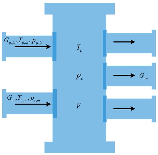
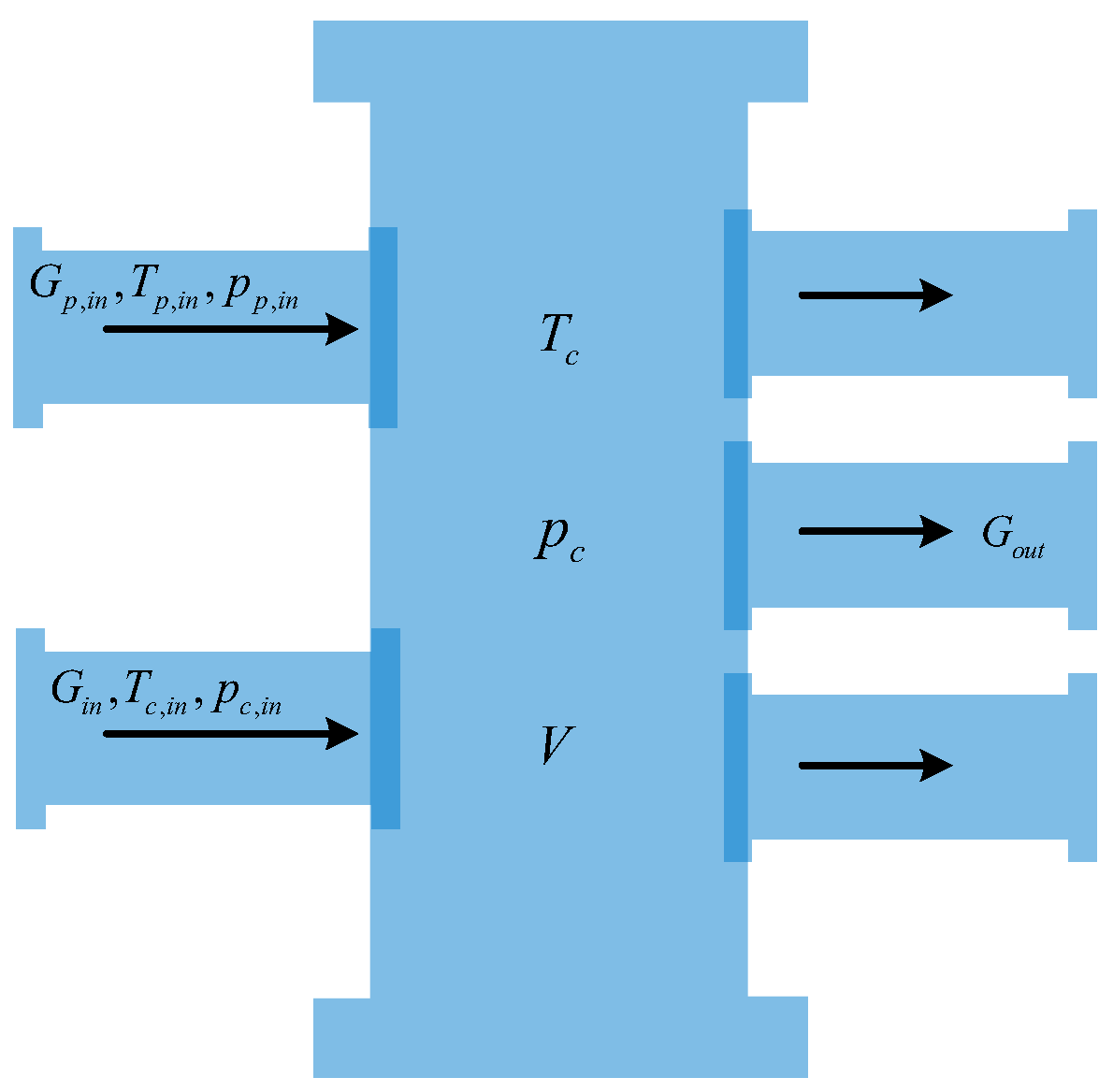
The pressure regulation system can be simplified into a cavity structure with two inlets and multiple outlets, as shown in Figure 3. Among them, are the gas flow, temperature, and pressure flowing into the exhaust main pipe from the engine. They are the main sources of disturbance in the exhaust main pipe. are the gas flow, temperature, and pressure flowing into the exhaust main pipe through the air supply valve. are the temperature, pressure, and volume of the main pipe. is the sum of gas flow out of the main pipe. According to the laws of thermodynamics, temperature and pressure equations of cavity of main pipe are obtained as
where R is the gas constant and are the enthalpy value of the exhaust outlet and the discharge flow rate of the exhaust outlet, respectively. is the heat exchange amount.
Figure 3.
Cavity structure of main exhaust pipe.
This paper focuses on the safe constraints of the pressure ratio of compressor in the pressure regulation system and the control of main pipe. It allows for the simultaneous operation of multiple compressor units. The exhaust gas of engine enters the pressure regulation system, which needs to be cooled by multiple coolers. It can be considered that the temperature of the main pipe is approximately unchanged . The airflow and inner wall of the pipe enter a thermal equilibrium state , and the enthalpy values of all outlets of the main pipe are basically equal.
2.3. Mathematical Model of Regulation Valve
In the pressure regulation system, the regulating valve is an important actuator. Among them, the inlet valve, the vent valve, and the anti-surge valve are all butterfly valves. Regulating valve is a plunger valve for the pressure of main pipe. The simulation shows that the regulating valves used in actual systems can track changes in setting instructions well [26]. Therefore, the models for the butterfly valve and plunger valve can be simplified to an equivalent inertia element.
2.3.1. Model of Butterfly Valve
The model of butterfly valve can be simplified to a first-order inertia unit [28], and its motion equation is
where is the butterfly valve opening and is the proportional coefficient. is the time constant, and is the control quantity of the butterfly valve. The flow formula of the butterfly valve can be simplified as
where is the mass flow rate of the butterfly valve and is the density of working fluid upstream of the butterfly valve. is the pressure difference before and after the butterfly valve. is the throttle hole area of the butterfly valve, and is the flow coefficient of butterfly valve, whose characteristics are shown in [25].
2.3.2. Model of Plunger Valve
The model of plunger valve can be simplified to a second-order inertia unit [29] below,
where is the opening of plunger valve and is the damping ratio. is the frequency of undamped oscillation, and is the control quantity of plunger valve. According to [11], the simplified flow model of the plunger valve is
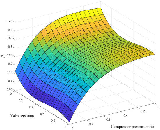
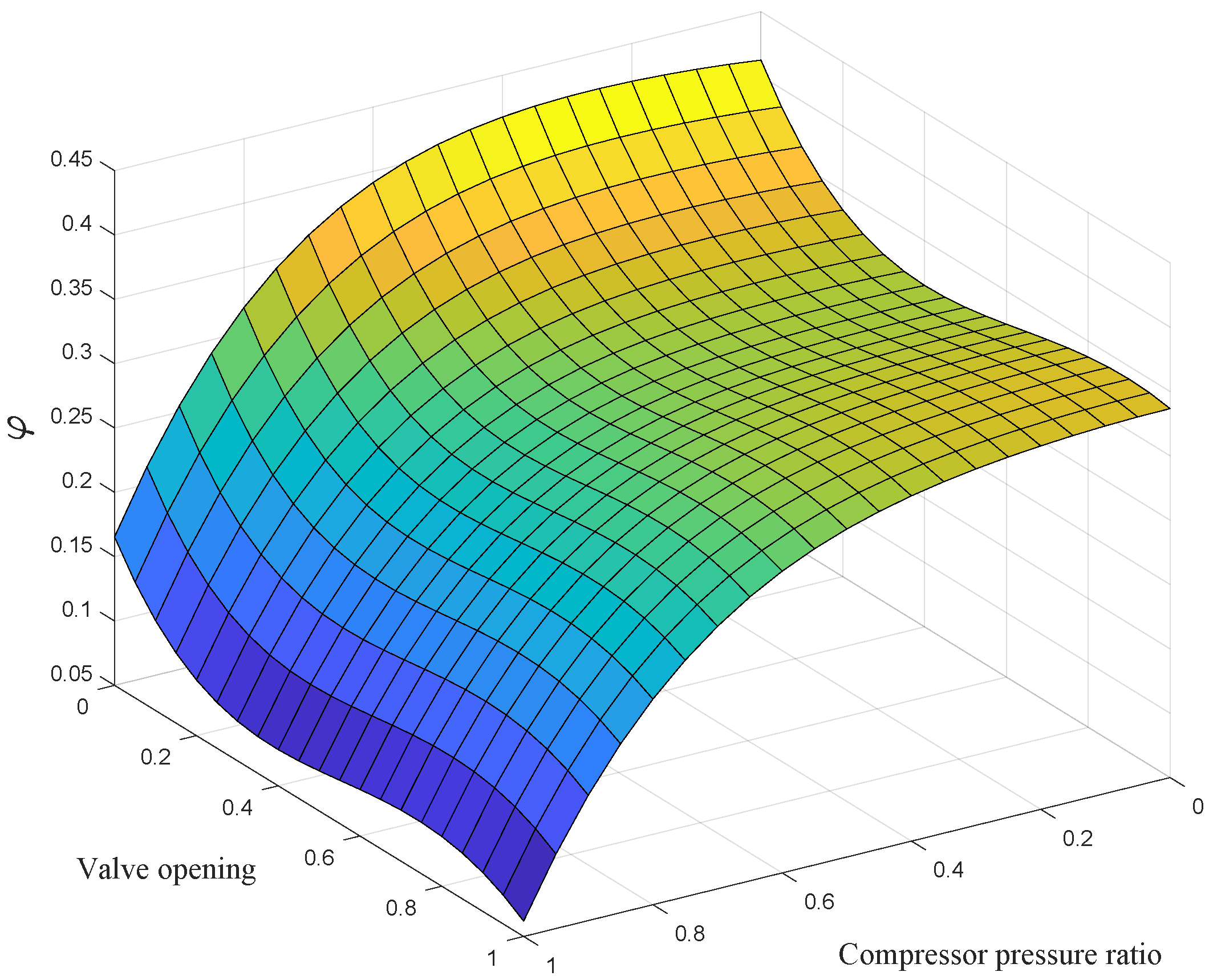
where is the mass flow rate of the plunger valve. S is the flow area, which is proportional to the opening of valve. are the inlet pressure and temperature of the plunger valve. is the flow coefficient of the plunger valve, whose characteristic curve is shown in Figure 4. Therefore, the flow rate out of the main pipe can be expressed as
Figure 4.
Plunger valve flow characteristic surface figure. The color gradient from blue to yellow represents the increasing magnitude of the flow coefficient .
2.4. Closed-Loop Control System
The exhaust gas from the compressor units and the engine is treated as external disturbances to the main pipe. According to Formulas (3), (4) and (6), the transfer function between the flow rate of air supply valve and the exhaust pressure of main pipe can be obtained as
with
The valve position model of the plunger valve is a second-order inertial unit, where . Its transfer function can be written as
Assume is a time constant, and simplify the model of plunger valve according to Taylor expansion
Although high-order dynamic terms are ignored, the simplified model is consistent with the characteristics of the actual system [27]. In the flow model of plunger valve, the flow area is in the form of a quadratic function. When the opening of valve ranges in , it can be approximated as a linear function. The flow transfer function is presented as follows:
where is the linear conversion coefficient.
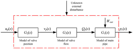
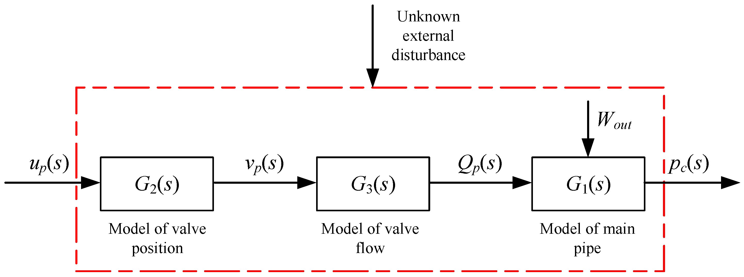
From the above transfer functions, according to Figure 5, the transfer function of the controlled object is
By transforming the above equation into the differential equation, we get
where is the external disturbances caused by the inlet valve and compressor to the main pipe and w is the external total disturbance. and are model parameters. b is the control gain as follows:
The main parameters in the above model are presented in Table 1 [30].
Figure 5.
Schematic diagram of controlled plant.
Table 1.
The Main Parameters Of The Model.
3. Design of Decentralized Cooperative Update Algorithm
In this paper, decentralized refers to the implementation architecture of the cooperative valve regulation, where each valve computes its update locally based on locally available measurements and predefined coordination rules, without a centralized coordinator or online global optimization. The cooperative nature is reflected in the controller structure: the local update law explicitly embeds shared objectives and coupling constraints through the augmented penalty terms, so that the inlet valve and the air supply valve coordinate their actions to regulate the main-pipe pressure while maintaining the compressor pressure-ratio within the safe range.
3.1. Problem Formulation
For pressure regulation systems, the safe operation of the compressor is the priority. At the same time, the exhaust pressure of main pipe is controlled to establish the pressure required for the flight environment. Compressor safety hazards are typically induced by surge and clogging. Surge is a major instability phenomenon in centrifugal compressors, characterized by large oscillations in pressure and mass flow of the system. Pressure ratio of compressor is an important indicator to measure the safety of compressor, expressed as the ratio of rear pressure of compressor to the front pressure . In the steady state, since the pressure regulation system directly discharges gas into the atmosphere, the pressure of main pipe directly affects the pressure ratio of compressor. According to the model, this relationship can be simplified as . Considering that the pressure ratio of compressor is constrained within a certain range, the problem is transformed into the following optimization problem
where is a continuously differentiable function, , , and is the target value. are the lower and upper bounds of the compressor safety pressure ratio. Let be the feasible domain of Problem (13). According to the above inequality constraints, the following auxiliary function is defined as
where is the penalty factor and is the penalty function. Combined with the characteristics of the exponential function, the penalty function is designed as
where the exponential function is used to ensure the existence of its derivative in the whole domain, which can accelerate the convergence rate of the system.
3.2. Design of Decentralized Control Algorithm
The current pressure regulation system exhibits poor anti-disturbance capability and low control accuracy, making it highly susceptible to disturbances and prone to producing large jumps. In order to prevent the system from being affected by shock jumps and sudden disturbances if the designed penalty factor is too large, a cooperative algorithm is designed to ensure smooth states and reduce the damage caused by valve jitter. The core units are designed as
where x is the state of the system. is the upper bound of state increment, which is updated by the second state estimate of the expanded state observer in the controller. For the safety of pressure of the main pipe and pressure ratio of the compressor, the core units are designed as
where . Combined with the above penalty function, the flexibility function is designed as
where is the state adjustment coefficient of the core unit. The auxiliary function with the core unit is used to design the augmented objective function as
where is the flexibility factor. Therefore, the optimization problem is transformed to
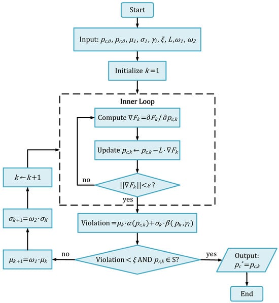
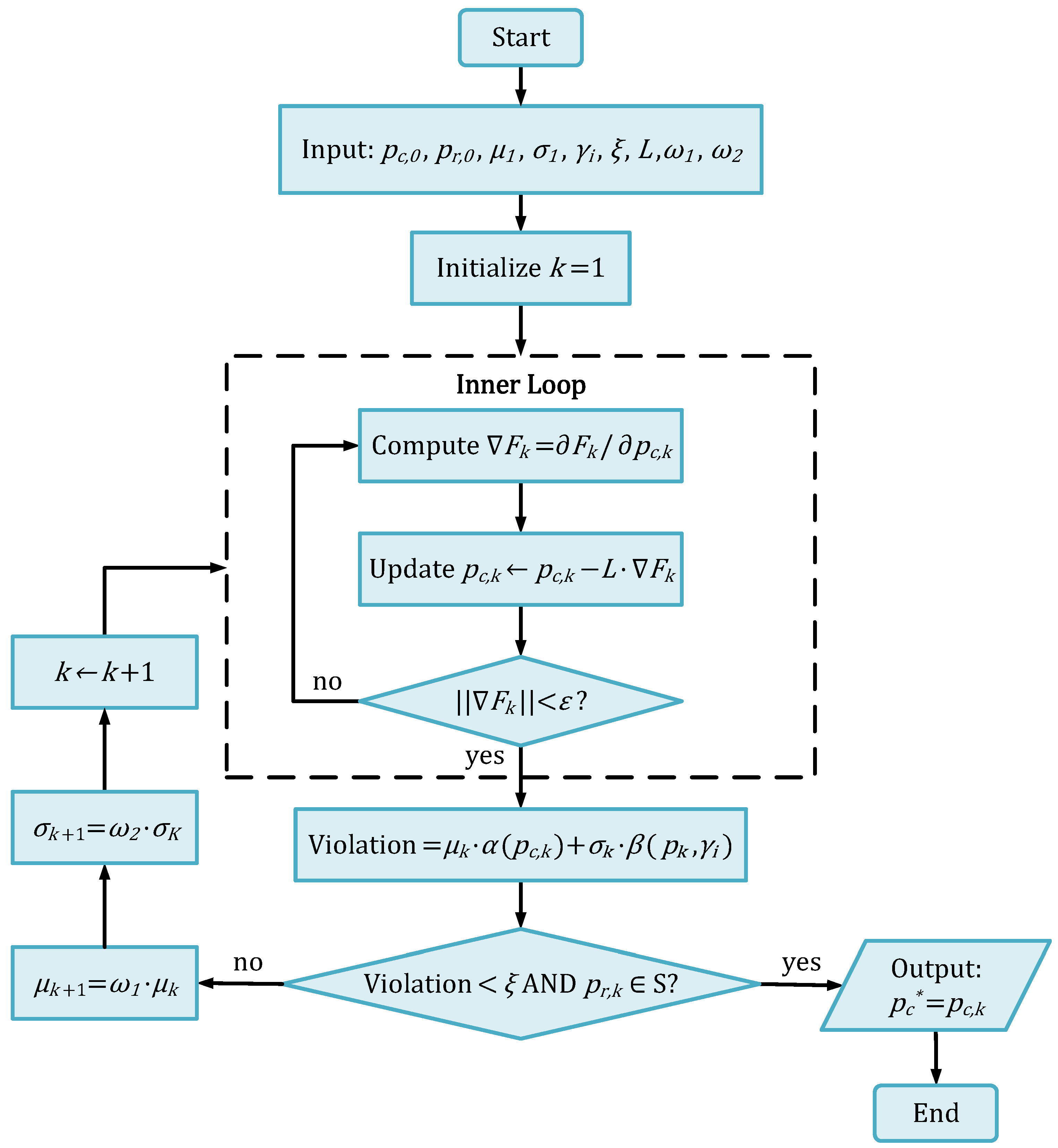
Once the system reaches the optimum, the optimal value of objective function is augmented, which ensures that the compressor is in a safe operating range and the pressure of main pipe reaches the expected value. The specific operation steps are presented in Figure 6. As shown in Figure 6, is the initial control state of pressure and is the control state at iteration k. is the final optimal solution found by the algorithm. is the initial response state of the pressure ratio and represents response state at iteration k. is the gradient of the objective function. and are initial values for the penalty factors. and are values at iteration k. L is the learning rate. and are scaling coefficients. is the tolerance threshold and is the gradient convergence threshold. S is the feasible region.
Figure 6.
Flowchart of the decentralized optimization-based cooperative control algorithm.
3.3. Convergence Analysis
In order to prove the convergence of above resilience algorithm and ensure that the optimal solution of constructed unconstrained problem is the optimal solution of original problem, the following Lemma is obtained.
Lemma 1.
For any and , if there exists such that
the following two claims hold:
- (1)
- .
- (2)
- are non-increasing functions with respect to μ and σ, respectively, and are non-decreasing functions with respect to .
Proof of Lemma 1.
According to Chapter IX of [31], the equation transformation (22)+(23) can be obtained , as approaches infinity, , , thus is a non-increasing function with the parameter . The same can be said for , , is a non-increasing function with the parameter . According to (23), , is a non-decreasing function. From (23), we can get and . Therefore, , is a non-decreasing function. □
Consider a feasible point , which is located within the safety range of ,
The amount of state change is very small when reaching steady state. By adjusting the parameters , let , thus
- (1)
- , so .
- (2)
- According to , let , we can get
Lemma 2.
Proof of Lemma 2.
Problem (13) has a feasible solution that satisfies . According to compressor model, we can obtain the relationship expression of pressure ratio, , where . When the inlet valve is fully open and the anti-surge valve is fully closed, the inlet pressure of compressor is approximately the pressure of main pipe, . At this time, the pressure of main pipe remains basically stable, so that . Thus, ; it only needs to satisfy to have a solution. Solving the inequality, we get when . The pressure of the main pipe is bounded by structural limitations. We can get , where serves as an upper bound for . Let , so that . Thus, the proof is completed. □
Theorem 1.
The limit point of any convergent subsequence is a global optimal solution, .
Proof of Theorem 1.
First, we prove that and have the upper bounds, then prove that the limit of is a feasible solution to the problem, and finally prove . The specific process is as below.
- Let be the optimal solution to the problem . By Lemma 1, we can deduce that the inequality . By Lemma 2, .
- When , . For any convergent subsequence represented by , Lemma 1 implies: . Let be the limit of ; therefore, . When , . This implies that is a feasible solution to Problem (13).
- By Lemma 1, we know that is the optimal solution, . When , . Thus, .
□
Remark 1.
The aforementioned optimization problem can be efficiently solved by adopting classic numerical optimization techniques, such as the quadratic programming method, interior point method, and Lagrange multiplier method. In this paper, control theory-based methodologies are adopted to address the aforementioned optimization problem. The detailed design of the corresponding controller is presented below.
4. Design of Cooperative Controller
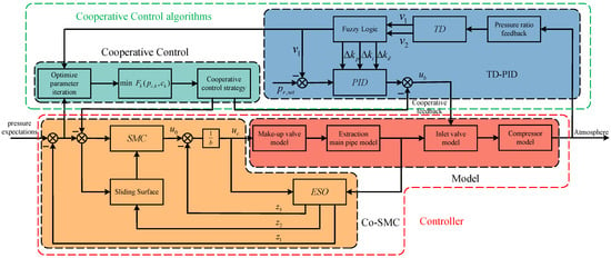
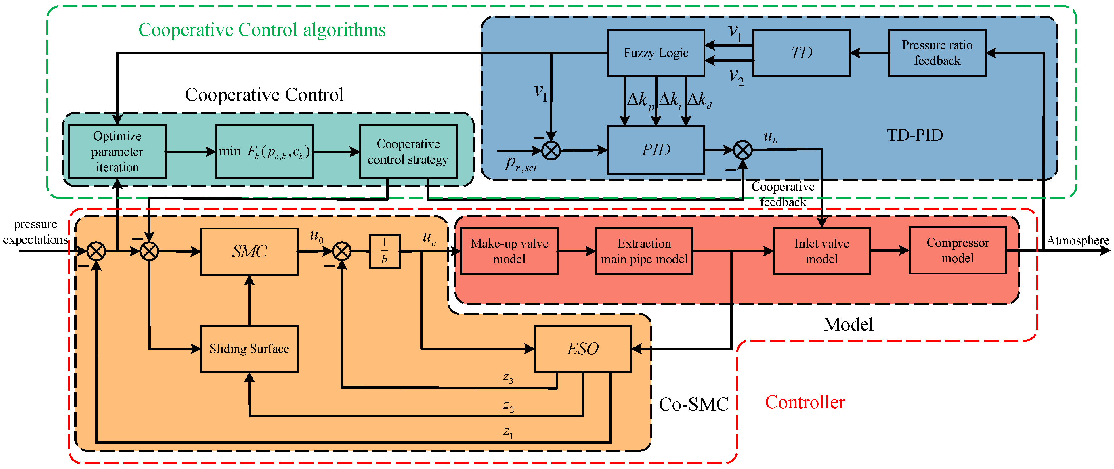
Since the pressure of main pipe is greatly affected by engine disturbances, the SMC is used to improve the stability of the system and reduce the fluctuation of pressure in the main pipe. The system model with the main pipe is complex. Therefore, PID control is preferred here since it does not rely on an accurate model. PID can control the pressure ratio well before the system is fully loaded, but it is lost after the inlet valve is fully opened. Fuzzy control can be used to optimize the PID parameters. In order to ensure that the pressure ratio of compressor is within the normal range, according to the optimization algorithm in Section 3, a cooperative control strategy is designed to control the pressure and pressure ratio simultaneously. Subsequently, the algorithm parameters are optimized and iterated according to the system state. Finally, the optimization problem is updated, and the process is iterated until the pressure ratio and pressure converge to the desired requirements, respectively. The specific control process is shown in Figure 7.
Figure 7.
Cooperative control architecture of pressure regulation system.
4.1. TD-Based Cooperative Controller of Inlet Valve
A tracking differentiator (TD) is designed to filter the signal of the pressure ratio and reduce measurement noise while providing its differential signal for feedback control. The state space model of the system is
where are the tracking setting value, the filtered input, and the differential of the filtered input, respectively. r is the fast factors, which affects the convergence speed of TD. By combining the optimization algorithm and TD, the following cooperative controller is designed. The control input of the inlet valve is designed as
where , is the cooperative optimization term. is a column vector where the ith element is 1 and all other elements are 0. are controller parameters. The controller parameters are adjusted by adaptive fuzzy control which is detailed in Appendix A, and the fuzzy input is the error e of pressure ratio and the rate of change in pressure ratio error . The design controller structure diagram is shown in Figure A1. Based on the error and its rate of change, the controller parameters are corrected, and these real-time adjustments are used to compensate for the initial parameters [32]. Note that the inlet valve only controls the compressor before it reaches full load operation. Once the compressor achieves its rated power following a backflow start-up, the inlet valve will be fully opened. Therefore, the control law for inlet valve is as follows:
where is the time at which the compressor achieves its rated power (i.e., the time corresponding to the completion of the backflow start-up). is the compensation coefficient, which makes the inlet valve open at a certain rate until it is fully open.
4.2. Cooperative SMC for Air Supply Valve
According to (12), the system model is expanded with an augmented state such that . The extended state-space system is
where the state variable is and the correlation matrix is
According to [33], the following ESO is obtained:
where state estimation is . The ESO gain matrix is , and is the output state estimation error. According to the bandwidth method [34], the specific parameters of ESO gain matrix can be obtained as . According to the ESO and SMC, the sliding surface is designed as
where is a design constant and are positive odd numbers satisfying . Combined with the objective function and based on the sliding mode control, the following cooperative control law is designed as
with
where determine the speed of controller convergence and the jitter magnitude. is the parameter of the function, and the jitter is generated by the sliding mode control. is the cooperative optimization item, where . Assuming that the ESO estimation result is accurate, the total disturbance of the system is , so the control law can be designed as
4.3. Stability Analysis
Theorem 2.
If , where are known upper bound, the design controller makes the closed-loop system state reach the sliding surface and converge to the origin. Then the closed-loop system (12) is stable if .
Proof of Theorem 2.
Consider the Lyapunov function as below:
The time derivative Lyapunov function yields
Since are positive odd numbers when and , if we set , we can get . The system (12) is stable. □
Remark 2.
The primary disturbance affecting the pressure regulation system stems from the exhaust gas flow of engine. Given that the maximum exhaust flow is constrained by capacity of pipeline and the flow rate changes smoothly, the nonlinear total disturbance is not only bounded above but also differentiable. The mechanical structure restricts the opening rate of valve. The change in pressure in the main pipe is continuous, so the gradient of the augmented objective function is also continuous. The objective function composed of the exponential penalty function is obviously differentiable. The maximum rate of change is determined by the change rate of pressure of the main pipe and the pressure ratio. The rate of change is determined by the opening of valve, so it has an upper bound and satisfies the condition of assumption .
5. Simulation Results
In this section, the hardware-in-the-loop simulation platform is built first, and its workflow is introduced. Second, the simulation parameters and the control objectives are determined. Finally, the effect of individual control and Co-SMC control are compared and discussed.
5.1. Experimental Set-Up
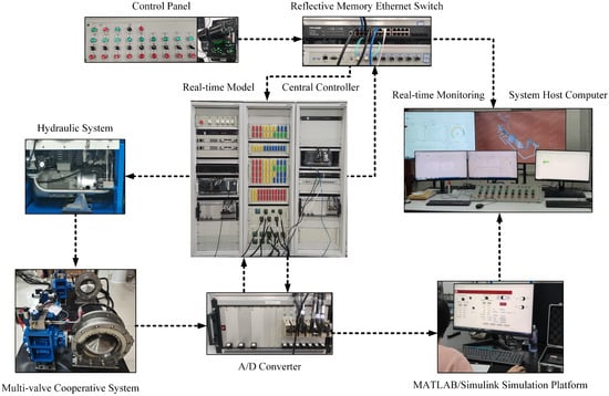
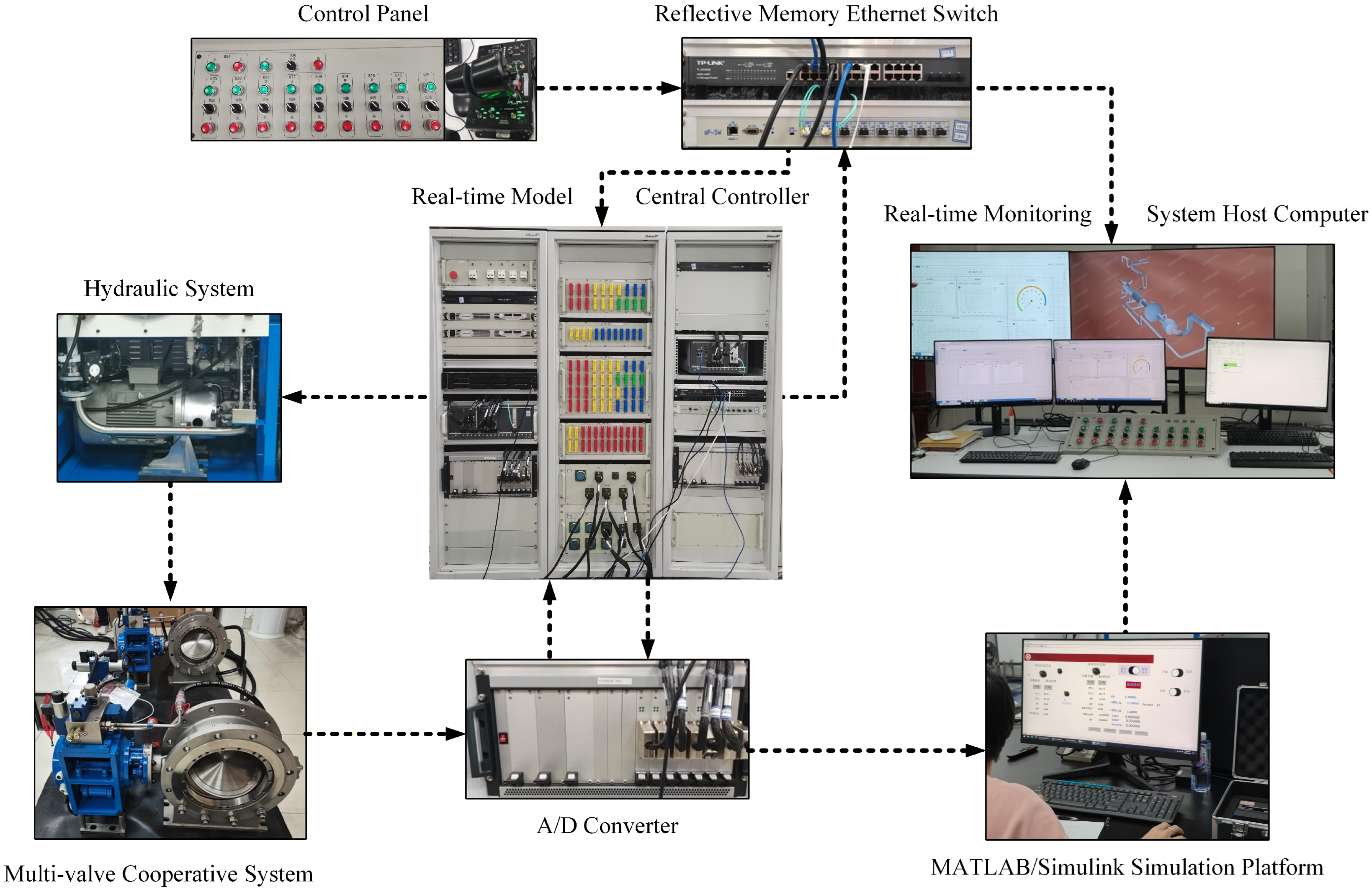
Based on the above models and controllers, a hardware-in-the-loop simulation platform for the pressure regulation system was built through MATLAB/Simulink to verify the effectiveness of the designed control algorithm, as shown in Figure 8. Since the proposed algorithm is designed to address compressor safety, it considers the effects of pressure ratio variations and external disturbances on the main pipe pressure under various complex operating conditions. The simulation addresses the simultaneous operation of two compressors, including the process of compressor return start-up and return flow connection to the grid. In the initial state, all inlet valves are closed, the anti-surge valve is fully open, the regulating valve of main pressure is fully closed, and the vent valve is also fully closed. At the final steady state, the unit inlet valve is fully open, and the anti-surge valve is fully closed. When the pressure regulating valve (i.e., the air supply valve) is opened to a certain angle, the main pipe pressure is established and gradually reaches a steady state. At present, the working pressure ratio of the compressor unit ranges from 2.5 to 9.5, and the surge protection pressure ratio is about 10.5. The compressor pressure ratio should remain within the safe range of 4.0–6.0 throughout the process. In the first-level regulation stage, the main pipe pressure gradually transitions from the initial atmospheric pressure (about 95.5 kPa) to the initial setting value of pressure. We compare the simulation results of the cooperative control with the multi-valve synchronization method.
Figure 8.
Hardware-in-the-loopsimulation platform.
5.2. Parameters Setting
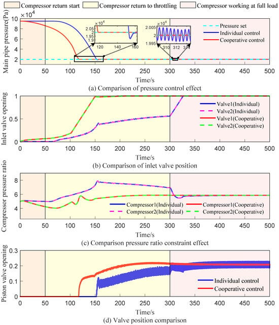
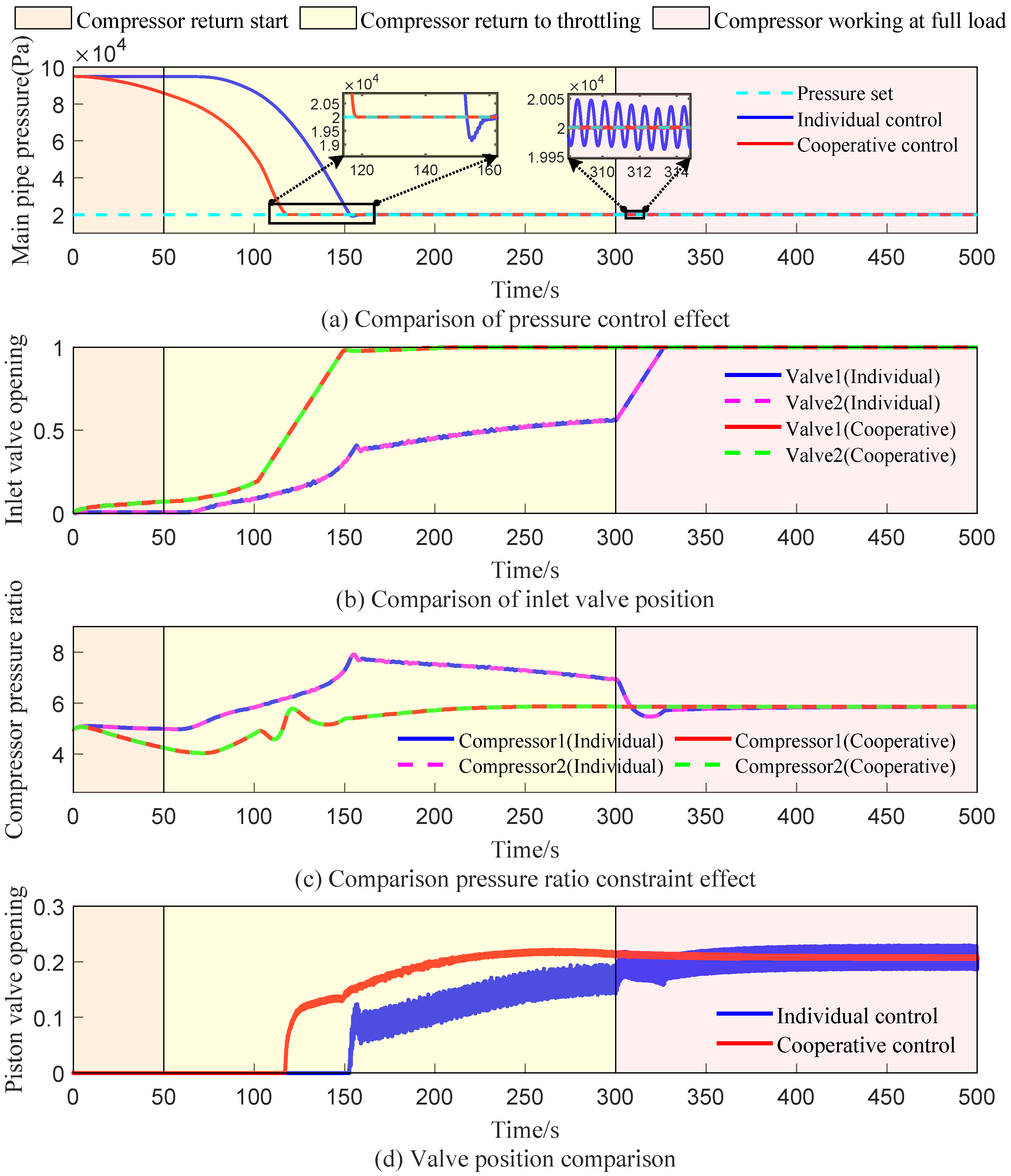
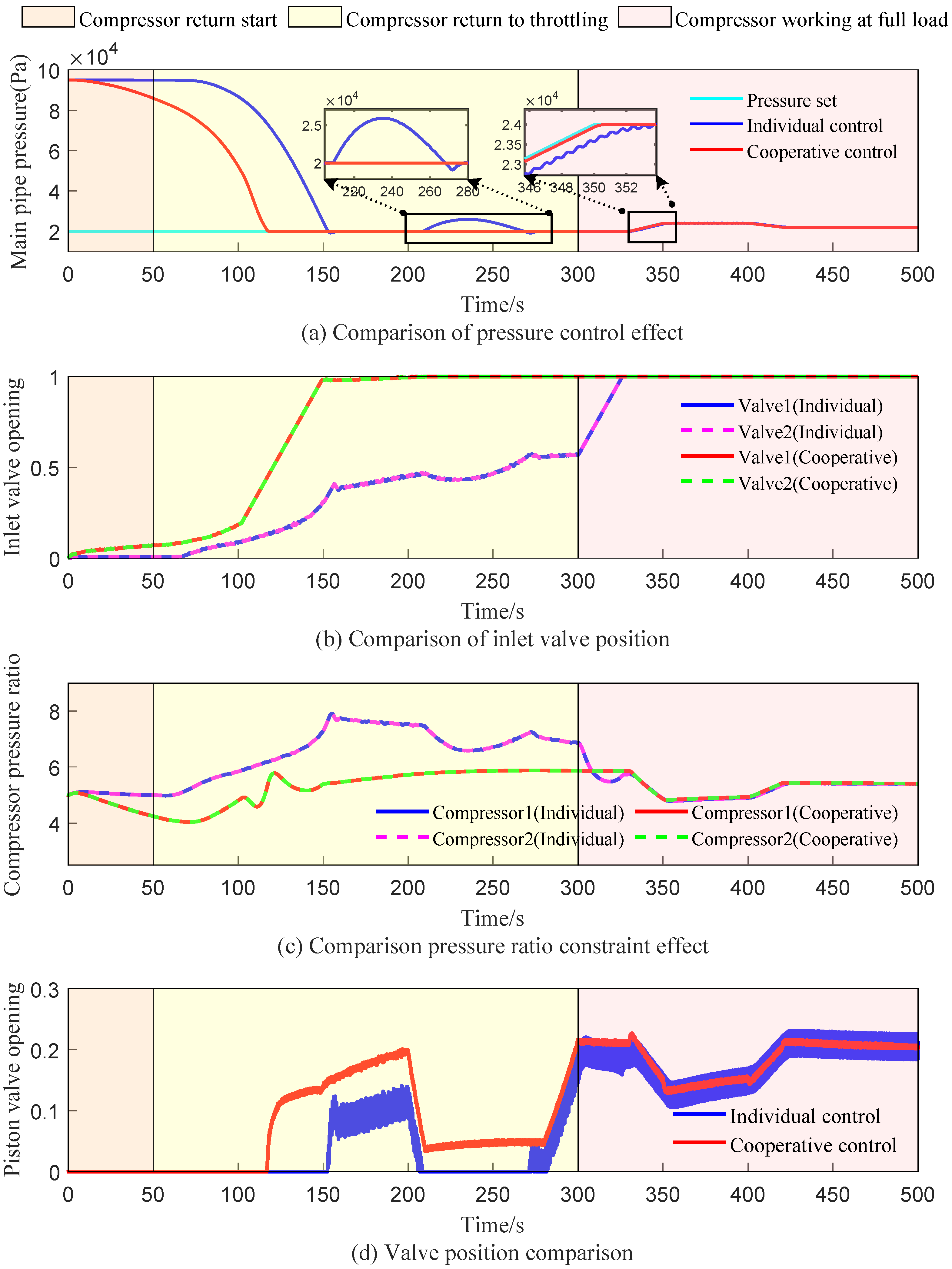
To verify the cooperative SMC method, the pressure regulation system is simulated. The expected value of the pressure of main pipe is kPa, and the constraints of pressure ratio are and . The pressure ratio bounds are selected according to the safe operating envelope of the compressor and anti-surge considerations. The lower bound prevents operation near unstable low-pressure-ratio regions, and the upper bound avoids excessive loading and efficiency degradation, thereby providing a conservative safety margin during mode transitions and disturbance propagation. The manipulated variables are the opening of inlet valve and the opening of air supply valve, both limited to the actuator range . The process variables are the main-pipe pressure and the compressor pressure ratio. The opening of the air supply valve is simulated, which is then compared with the individual control method. Simulation results are shown in Figure 9, and the main parameters of controller are presented in Table 2. To improve reproducibility, the simulation starts from a steady operating point under nominal exhaust-flow conditions, and the disturbance scenarios follow the profiles reported in Figure 9. According to the magnitude of the error and its rate, fuzzy rules are designed and documented in Table A1. In addition, the algorithmic parameters are selected to balance convergence speed, constraint enforcement, and actuation smoothness. Specifically, the initial penalty and flexibility factors are set to moderate values to avoid overly aggressive constraint enforcement at the beginning. The multiplicative update factors and progressively strengthen the penalty when the constraint-violation measure remains above the threshold . The learning rate L is chosen through a short sensitivity test to ensure stable descent of the augmented objective in the inner-loop update while achieving convergence within a limited number of iterations. The tolerance parameters and are set as small positive values to terminate the iterations once the gradient norm becomes sufficiently small, thereby trading off numerical accuracy and computational cost for real-time feasibility. These settings provide a reproducible implementation guideline for the proposed penalty-based cooperative control scheme.
Figure 9.
Comparison of control results.
Table 2.
The Main Parameters of The Controller.
5.3. Comparison and Discussions
The operation process of the pressure regulation system can be divided into three parts: 0∼50 s is the stage from stop to initial startup of compressor; 50∼300 s is the anti-surge process started by the compressor backflow. The anti-surge valve operates from a fully open to a fully closed position, while the inlet valve simultaneously opens to a specific angle to provide auxiliary regulation, thus mitigating surge caused by an excessive pressure ratio of compressor. At this time, the inlet and outlet pressures of compressor achieve the required regulation state. The range of 300∼500 s encompasses the backflow and grid connection process. The inlet valve opens at a certain rate until it is fully open, and the pressure regulating valve opens to a certain angle.
The performance of the individual control and Co-SMC methods is compared under constant engine exhaust flow conditions. The setpoint is 20 kPa. The manipulated variables are the opening of the inlet valve and the air supply valve (i.e., the piston valve), as shown in Figure 9b,d. The process variables are the main pipe pressure and the compressor pressure ratio, as shown in Figure 9a,c. Figure 9a shows the main pipe pressure response. Under individual control, the pressure reaches the setpoint with noticeable overshoot and steady oscillations. In contrast, Co-SMC reaches the setpoint with zero overshoot and negligible oscillation, demonstrating a faster and smoother dynamic response. Figure 9c presents the pressure ratio behavior. Individual control causes the pressure ratio to exceed the safe operating range during the transient process and remain outside the safe region for an extended period before recovering. By comparison, Co-SMC maintains the pressure ratio within the safe range throughout the entire regulation process. Figure 9b compares the inlet valve dynamics. Individual control exhibits slow and delayed opening characteristics, and full-load operation is achieved only at a late stage. In contrast, Co-SMC enables smooth initial opening under cooperative regulation. The penalty mechanism accelerates valve opening, allowing faster convergence to full-load operation. Figure 9d shows the response of the air supply valve. Significant oscillations are observed under individual control, which degrade regulation performance. Co-SMC effectively attenuates these oscillations, thereby lowering the probability of valve failure.
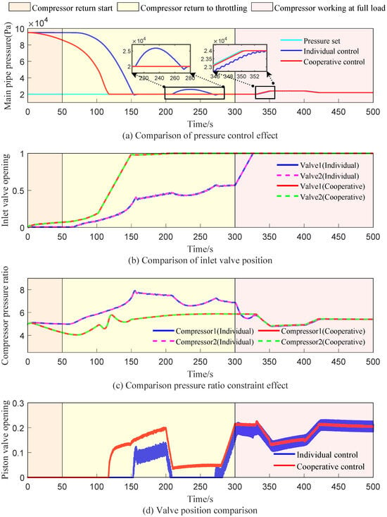
To evaluate robustness under realistic operating variations, multiple disturbances are introduced, and the simulation results are shown in Figure 10. The setpoint of pressure is adjusted within the interval of 330∼420 s, as shown in Figure 10a. A leakage fault of 60 kg/s is introduced into the pressure regulating valve during the compressor return to throttling at 200 s. In addition, the engine discharge flow begins to increase at 330 s, rising to 30 kg/s, before dropping to 10 kg/s at 400 s. Figure 10a shows the main pipe pressure response. Under the influence of the valve fault, individual control loses regulation from 208 s to 278 s, and the main pipe pressure rises to 26 KPa. In contrast, Co-SMC maintains stable pressure regulation, with the valve fault having negligible impact on the main pipe pressure. Under engine exhaust flow disturbances, individual control results in a noticeable static pressure deviation, while Co-SMC effectively minimizes it. Under fault conditions of pressure regulating valve, as shown in Figure 10b,c, individual control induces noticeable fluctuations in both the inlet valve opening and the compressor pressure ratio compared with the fault-free case. In contrast, Co-SMC maintains stable actuation of inlet valve and ensures that the compressor pressure ratio closely tracks its setpoint. In addition, compared with individual control, Co-SMC has a significant inhibitory effect on the oscillation, which is caused by regulation of pressure regulating valve, as shown in Figure 10d.
Figure 10.
Comparison of control results under special working conditions.
To complement the qualitative comparisons in Figure 10, Table 3 provides a numerical evaluation between the individual control and the proposed cooperative control. The cooperative control reduces the pressure-tracking RMSE from 53.64 kPa to 5.58 kPa, eliminates overshoot, and shortens the settling time from 160 s to 119 s. Regarding safety, the compressor pressure ratio is maintained within the prescribed range throughout the regulation process, whereas individual control cannot guarantee this constraint during transients. Moreover, Co-SMC effectively suppresses air-supply valve oscillations, reducing the valve swing from to , which improves actuation smoothness. Finally, under exhaust-flow disturbance, the steady pressure deviation is reduced from 0.5 kPa to 0.1 kPa, demonstrating improved robustness.
Table 3.
Numerical evaluation comparing individual control and cooperative control.
In terms of engineering applicability, the proposed scheme requires only lightweight online computations. Each sampling step performs a small number of gradient-based updates with a low-dimensional decision variable and simple algebraic operations, while the main modeling and parameter tuning are completed offline. To meet real-time constraints on embedded platforms, the inner-loop iteration can be capped to a fixed and small number with a warm start from the previous step. A simplified fallback controller can be used when computation resources are limited. Importantly, the proposed coordination is executed through local valve updates and does not require online centralized optimization, which makes the implementation compatible with real-time control loops.
6. Conclusions
This paper develops a safe cooperative control method for multiple compressor units and validates its effectiveness through theoretical analysis and numerical simulations. By formulating the compressor pressure-ratio safety requirement as inequality constraints and embedding it into a penalty-based optimization framework, the constrained problem is transformed into an implementable cooperative control algorithm that coordinates multi-valve actions. The results show that the proposed method keeps the pressure ratio within the prescribed safe range while regulating the main-pipe pressure toward the set value. Compared with the individual control strategy, it improves transient performance and significantly reduces valve jitter. For practical deployment, several practical issues must be addressed, including ensuring that the cooperative update can be executed within the sampling period, maintaining stable performance under sensor noise and actuation delays, adapting to model mismatch and parameter drift in valve dynamics, and explicitly handling actuator amplitude and rate limits. Future work will extend the framework to multi-stage pressure regulation systems and larger-scale multi-compressor coordination as well as explore an optional distributed extension with limited inter-unit communication to improve scalability and engineering applicability.
Author Contributions
Conceptualization, C.Z., X.Q. and Y.F.; methodology, X.Q.; software, X.L., X.Q. and Y.F.; validation, X.Q. and Y.F.; analysis, X.Q., X.L. and Y.F.; investigation, X.Q., Y.F., X.L., C.Z., H.Z. and W.Z.; resources, C.Z., H.Z. and W.Z.; data curation, X.Q., Y.F. and X.L.; writing—original draft preparation, X.Q., Y.F. and X.L.; writing—review and editing, X.Q. and Y.F.; visualization, X.Q. and X.L.; supervision, C.Z., H.Z. and W.Z.; project administration, C.Z., H.Z. and W.Z.; funding acquisition, C.Z., H.Z. and W.Z. All authors have read and agreed to the published version of the manuscript.
Funding
This work was supported by the Stable Support Project of the Sichuan Gas Turbine Research Institute, Aero Engine Corporation of China (AECC) under Grant No. GJCZ-0101-2024-0008.
Institutional Review Board Statement
Not applicable.
Informed Consent Statement
Not applicable.
Data Availability Statement
The original contributions presented in this study are included in the article. Further inquiries can be directed to the corresponding author.
Conflicts of Interest
Author Wei Zhao was employed by Sichuan Gas Turbine Research Institute, Aero Engine Corporation of China. The remaining authors declare that the research was conducted in the absence of any commercial or financial relationships that could be construed as a potential conflict of interest.
Appendix A
Figure A1.
Fuzzy control schematic.
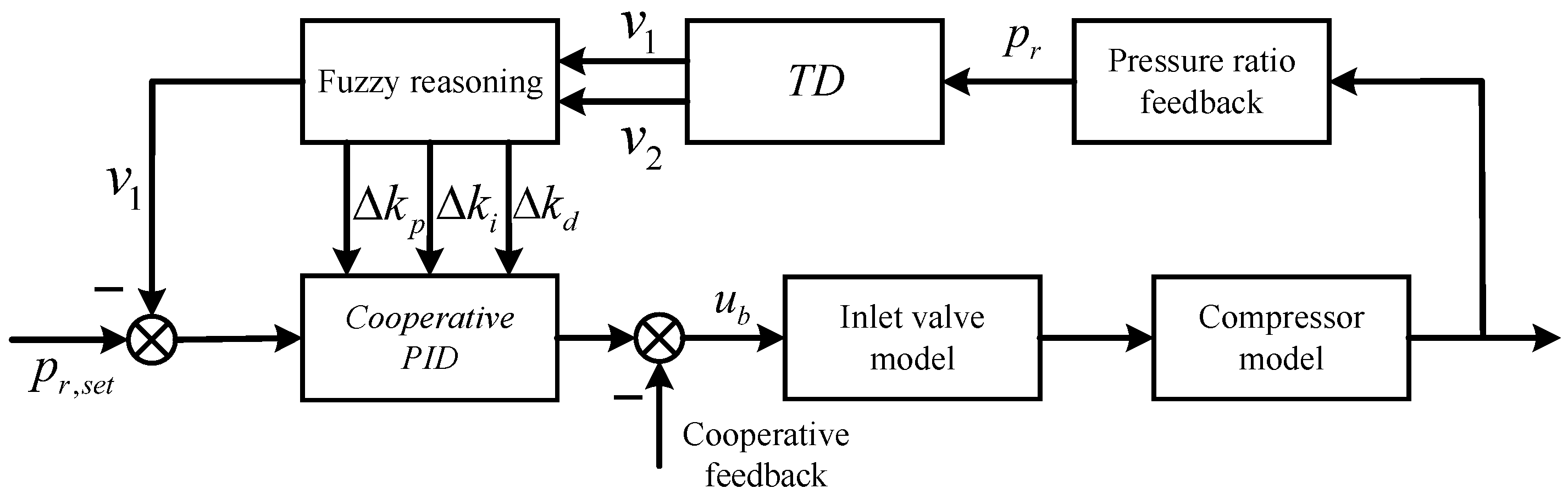
For adjustment of fuzzy control parameter, the input is fuzzy and normalized. It is converted into continuous variables to generate seven fuzzy subsets, including negative large (NB), negative medium (NM), negative small (NS), zero (ZO), positive small (PS), positive medium (PM), and positive large (PB). The membership function uses the Gaussian function as
where a determines the position of function and b determines the curvature of function.
Table A1.
Fuzzy Rule Table.
References
- Pei, X.; Wang, X.; Liu, J.; Zhu, M.; Dan, Z.; He, A.; Miao, K.; Zhang, L.; Xu, Z. A review of modeling, simulation, and control technologies of altitude ground test facilities for control application. Chin. J. Aeronaut. 2023, 36, 38–62. [Google Scholar] [CrossRef] [Scilit]
- Weisser, M.; Bolk, S.; Staudacher, S. Hardware in-the-loop simulation of a feedforward multivariable control for the altitude test facility at the University of Stuttgart. In Proceedings of the Deutscher Luft-und Raumfahrtkongress, Stuttgart, Germany, 10–12 September 2013. [Google Scholar]
- Luppold, R.H.; Meisner, R.; Norton, J.M. Design and evaluation of an auto-tuning control system for an altitude test facility. In Proceedings of the Turbo Expo: Power for Land, Sea, and Air, Indianapolis, IN, USA, 7–10 June 1999. [Google Scholar]
- Li, J.; Fu, Z.; Luo, J. Equivalent stress model-assisted aero-structural optimization of a compressor rotor using an adjoint method. Modelling 2025, 6, 125. [Google Scholar] [CrossRef] [Scilit]
- Zagorowska, M.; Degner, M.; Ortmann, L.; Ahmed, A.; Bolognani, S.; del Rio Chanona, E.A.; Mercangöz, M. Online feedback optimization of compressor stations with model adaptation using Gaussian process regression. J. Process Control 2023, 121, 119–133. [Google Scholar] [CrossRef] [Scilit]
- Oh, Y.; Lee, C.J.; Lim, Y. A short-cut graphical method for sizing of recycle valves in anti-surge system considering time delay. J. Process Control 2017, 58, 23–32. [Google Scholar] [CrossRef] [Scilit]
- Zhou, Q.; Zhang, L.; Zhuang, C.; Jia, H. Study on matching calculation method and experimental technology of compressor gas source for ASTF. Chin. J. Turbomach. 2017, 59, 48–55. [Google Scholar]
- Zhou, Q.; Zhuang, C.; Fang, J.; Jia, H. Adaptation transformation of gas source for high-altitude simulation test facility. Plant Maint. Eng. 2017, 8, 45–47. [Google Scholar]
- Wang, B.; Tang, S.; Wan, S.; Zhang, H. PLC digital PID control of the air deflation system airflow supply of altitude test facility. Gas Exp. Res. 2010, 23, 30–34. [Google Scholar]
- Dong, M.S.; Liu, Z.Y.; Li, X.T.; Tang, F.Z. Optimal control structure design for air extraction system of the simulated altitude test facility. Gas Exp. Res. 2018, 31, 42–45. [Google Scholar]
- Jia, W.; Wang, X.; Zhong, L.P.; Zhang, S.; Dan, Z.H. Characteristics and acceptance maintenance regulations of altitude test platform plunger regulating valve. Sci. Tech. Innov. Herald 2015, 12, 105–107. [Google Scholar]
- Su, Y.; Wang, X.; Chen, X.J.; Ai, W.S.; Wang, T.Q.; Li, X.D.; Liu, X.M. Research on dynamic simulation method for air supply compressor unit of altitude test facility. J. Propul. Technol. 2022, 43, 210444. [Google Scholar]
- Dong, Y.; Zhou, Y.; Zou, J.; Wang, X.; Li, X.; Cui, H. Grid-connection control method for air supply compressor unit of altitude test facility. Acta Aeronaut. Astronaut. Sin. 2023, 44, 327221. [Google Scholar]
- Cortinovis, A.; Ferreau, H.J.; Lewandowski, D.; Mercangöz, M. Experimental evaluation of MPC-based anti-surge and process control for electric driven centrifugal gas compressors. J. Process Control 2015, 34, 13–25. [Google Scholar] [CrossRef] [Scilit]
- Jung, J.; Lee, W.J.; Park, S.; Kim, Y.; Lee, C.J.; Han, C.H. Improved control strategy for fixed-speed compressors in parallel system. J. Process Control 2017, 53, 57–69. [Google Scholar] [CrossRef] [Scilit]
- Xu, L.; Chen, Y.L.; Chen, Y.T.; Nie, L.F.; Wei, X.T.; Xue, L.; Zhang, D.X. Swarm Learning for temporal and spatial series data in energy systems: A decentralized collaborative learning design based on blockchain. Appl. Energy 2025, 381, 125053. [Google Scholar] [CrossRef] [Scilit]
- Zuo, K.; Wu, L. A review of decentralized and distributed control approaches for islanded microgrids: Novel designs, current trends, and emerging challenges. Electr. J. 2022, 35, 107138. [Google Scholar] [CrossRef] [Scilit]
- Song, H.; Yang, Z.; Du, H.T.; Zhang, Y.T.; Zeng, J.; He, X.X. LLM-LCSA: LLM for collaborative control and decision optimization in UAV cluster security. Drones 2025, 9, 779. [Google Scholar] [CrossRef] [Scilit]
- Zhai, C.; Zhang, H.T.; Xiao, G. Cooperative Coverage Control of Multi-Agent Systems and Its Applications, 1st ed.; Springer: Singapore, 2021; pp. 1–136. [Google Scholar]
- Wang, G.R.; Sun, S.M.; Cheng, Y.; Yu, P.; Wang, S.B.; Zhao, X.S. Multi-agent proximal policy optimization for coordinated adaptive control of photovoltaic inverter clusters in active distribution networks. Energies 2026, 19, 978. [Google Scholar] [CrossRef] [Scilit]
- Imani, H.; Jahed-Motlagh, M.R.; Salahshoor, K.; Ramezani, A.; Moarefianpur, A. Robust decentralized model predictive control approach for a multi-compressor system surge instability including piping acoustic. Cogent Eng. 2018, 5, 1483811. [Google Scholar] [CrossRef] [Scilit]
- Yilmaz, F.C.; Onler, R.; Tatlicioglu, E.; Zergeroglu, E. A transfer learning based deep neural network adaptive controller for the Furuta pendulum subject to uncertain disturbance signals. Sci. Rep. 2025, 15, 24012. [Google Scholar] [CrossRef] [Scilit]
- Gao, T.; Tomita, K.; Kamimura, A. Robustness enhancement for multi-quadrotor centralized transportation system via online tuning and learning. In Proceedings of the American Control Conference, Denver, CO, USA, 8–10 July 2025. [Google Scholar]
- Han, J.Q. From PID to active disturbance rejection control. Trans. IRE Prof. Group Ind. Electron. 2009, 56, 900–906. [Google Scholar] [CrossRef] [Scilit]
- Qian, Q.M.; Dan, Z.H.; Zhang, S.; Pei, X.T.; Wang, W. Linear active disturbance rejection control method for intake pressure control in aero-engine transient test. J. Aerosp. Power 2019, 34, 2271–2279. [Google Scholar]
- Zhu, M.Y.; Zhang, S.; Dan, Z.H.; Pei, X.T.; Wang, W.; Wang, X. A coordinate positioning and regression algorithm for the flow characteristics of a large butterfly valve. Gas Exp. Res. 2017, 30, 39–44. [Google Scholar]
- Dan, Z.H.; Zhang, S.; Bai, K.Q.; Qian, Q.M.; Pei, X.T.; Wang, X. Air intake environment simulation of altitude test facility control based on extended state observer. J. Propul. Technol 2021, 42, 2119–2128. [Google Scholar]
- Mu, Y.; Liu, M.; Ma, Z. Research on the measuring characteristics of a new design butterfly valve flowmeter. Flow Meas. Instrum. 2019, 70, 101651. [Google Scholar] [CrossRef] [Scilit]
- Ren, Y.; Bai, C.; Zhang, H. Dynamic modeling and combination analysis of plunger valve considering both flow and actuator. J. Appl. Fluid Mech. 2023, 17, 192–204. [Google Scholar]
- Zhang, S.; Zhu, M.; Dan, Z.; Pei, X.; Wang, X.; Wang, X. Integral type μ synthesis control of flight environment simulation volume. J. Propul. Technol 2018, 39, 660–666. [Google Scholar]
- Bazaraa, M.S.; Sherali, H.D.; Shetty, C.M. Nonlinear Programming: Theory and Algorithms, 3rd ed.; John Wiley & Sons: Hoboken, NJ, USA, 2006; pp. 652–668. [Google Scholar]
- Duan, X.; Li, H.; Deng, H. Robustness of fuzzy PID controller due to its inherent saturation. J. Process Control 2012, 22, 470–476. [Google Scholar] [CrossRef] [Scilit]
- Feng, H.; Guo, B.Z. Active disturbance rejection control: Old and new results. Annu. Rev. Control 2017, 44, 238–248. [Google Scholar] [CrossRef] [Scilit]
- Gao, Z. Scaling and bandwidth-parameterization based controller tuning. In Proceedings of the American Control Conference (ACC), Denver, CO, USA, 4–6 June 2003. [Google Scholar]

Disclaimer/Publisher’s Note: The statements, opinions and data contained in all publications are solely those of the individual author(s) and contributor(s) and not of MDPI and/or the editor(s). MDPI and/or the editor(s) disclaim responsibility for any injury to people or property resulting from any ideas, methods, instructions or products referred to in the content. |
© 2026 by the authors. Licensee MDPI, Basel, Switzerland. This article is an open access article distributed under the terms and conditions of the Creative Commons Attribution (CC BY) license.