


Abstract
Multi-grooved water-lubricated bearings (MGWLBs) are widely used in marine stern tube applications, where hydrodynamic performance is strongly influenced by groove geometry and operating conditions. This study presents a combined experimental and computational investigation of water film lubrication characteristics in MGWLBs with different groove geometries. An experimental test setup redesigned to replicate the operational behavior of MGWLBs was employed to record the circumferential film pressure variations under varying rotational speeds and applied loads. Detailed experimental tests were performed on a MGWLBs with filleted V-shaped grooves, where the film pressures at the bearing midplane were measured using a flush-mounted diaphragm pressure sensor mounted on a hollow shaft. The experimental results revealed a transition from localized, non-uniform pressure generation at low speeds to stable and circumferentially continuous hydrodynamic pressure fields at higher speeds and loads. CFD simulations were also conducted to analyze the influence of groove geometry on pressure distribution and flow behavior. An increase in rotational speed was shown to significantly enhance pressure magnitude, circumferential continuity, and film stability under moderate to high loading conditions. Filleted V-shaped, semicircular, and short V-shaped groove models were analyzed for a speed range of 400 to 6000 RPM. Filleted V-shaped grooves produced smooth pressure development with moderate gradients, while semicircular grooves improved pressure and velocity uniformity by limiting localized intensification. In contrast, short V-shaped grooves generated higher peak pressures due to enhanced flow acceleration at groove–land interfaces. The findings provide design guidance for selecting groove geometry and operating conditions to enhance the hydrodynamic performance of marine water-lubricated bearings.
1. Introduction
Water-lubricated stern tube bearings, recognized for their environmental friendliness and resource efficiency, have gained significant importance as sustainable solutions in ship propulsion systems and related marine applications [1]. Water-lubricated bearings (WLBs) provide significant benefits over traditional oil-lubricated metal bearings, including reduced oil consumption, less environmental pollution, and lower levels of friction, wear, and noise. Even their simple structure and ability to accommodate misalignments make them easy to install and maintain [2,3]. The United States Environmental Protection Agency’s draft bill requires ships built after 2013 to use biodegradable and non-toxic lubricants. Older vessels were also encouraged to transition to environmentally acceptable lubricants in order to minimize ecological impact. Water-lubricated bearings are widely used across various technologies, encompassing rubber [4,5], polymer [6], composite, ceramic [7], sintered metal alloy, and advanced multi-layer materials [8,9], with extensive research continuing on their respective advantages and limitations. The film pressure is a key performance parameter of water-lubricated rubber bearings and has attracted significant attention. However, due to factors like film space sealing, formation mechanisms, and varying bearing structures, measuring film pressure is very difficult, so most studies are theoretical rather than experimental [1]. Recent developments in bio-inspired surface designs, advanced coatings, and fabrication techniques offer effective pathways to enhance wear resistance and prolong the operational lifespan of water-lubricated bearings [10].
Several experimental studies have examined the influence of groove geometry and bush deformation on the film pressure distribution in water-lubricated bearings. In one of the notable studies, Wang et al. [5] experimentally measured the continuous film pressure distribution of WLBs with eight-axial grooves using a wireless technique. Bearing grooves had a significant effect on film pressures, and the rubber bush experienced deformation during operation. Bearings with concave staves formed a continuous water film in the load-carrying region, whereas in flat stave bearings, each stave exhibited its own pressure peak. The research group led by Litwin [11,12] has carried out several pioneering experimental studies on water-lubricated bearings, contributing significantly to the advancement of this field. Experimental studies by Litwin and Olszewski [9] indicated that water-lubricated bearing performance is highly dependent on bush material and geometry, with three-layer or partial-groove designs achieving lower friction, improved hydrodynamic lubrication, and higher load capacity than traditional rubber or full-groove bearings [13]. Further studies by Litwin [11,12] emphasized the roles of bush elasticity, surface finish, and proper running-in procedures in maintaining fluid film lubrication and reducing wear, particularly under low-speed and mixed-lubrication conditions. Test rig experiments showed that partial-groove and three-layer polytetrafluoroethylene (PTFE)/NBR (nitrile butadiene rubber)/brass bearings offer lower start-up friction, better misalignment tolerance, and greater durability than conventional NBR or polymer bushings [14,15]. Experiments showed that certain water-lubricated bearings can operate safely without continuous lubricant flow due to low friction and effective heat dissipation. Overheating tests indicated that temperature rise increases friction and limits torque, highlighting the need for proper thermal design and flow monitoring [16]. An earlier study examined the transient dynamics of a water-lubricated bearing–rotor system using a four-stage pump test rig, analyzing journal orbit and pressure distribution and showing improved stability with optimized clearance, aspect ratio, and speed [17]. Subsequent work on naval propulsion bearings used scaled experiments and EHL modeling to evaluate lubrication regimes, friction, and eccentricity variations with rotational speed [18]. Han et al. [19] experimentally evaluated water-lubricated bearings made of PEEK (polyether ether ketone), PI (polyimide), and NBR using a dedicated test rig, showing that PEEK provides the lowest friction and wear, while NBR offers superior vibration damping and rotor stability. Studies on WLBs exposed to contaminated water showed that particle ingress and dissolved salts can substantially increase wear, decrease load-carrying capacity, and modify frictional performance [20].
Xie et al. [21,22] conducted extensive experimental and numerical studies on water-lubricated bearings, covering surface texturing, cavitation behavior, rotor–bearing dynamics, and fluid–structure interaction effects. They showed that micro-cavity texturing in water-lubricated bearings modifies pressure distribution, reduces cavitation, and improves load capacity, with CFD results indicating that cavity geometry and Reynolds number control vortex behavior and film stability. Extending the numerical insights, Xie et al. [23] further developed a multifunctional rotor–bearing test rig with displacement and force sensors, enabling reduced shaft deflection and precise measurement of film thickness and friction forces. By accounting for the surface roughness, thermal balance, and bushing deformation, theoretical and experimental results consistently show that structural parameters such as clearance ratio, eccentricity, and bush thickness have a pronounced impact on pressure distribution, load capacity, and frictional behavior [24,25]. Tang et al. [26] analyzed the tribo-dynamic behavior of staved water-lubricated bearings, demonstrating the critical impact of stave geometry and operating conditions on their mixed-lubrication performance. Liu and Li [27] developed a specialized test rig with a hollow shaft and embedded micro-pressure sensors to measure film pressure in water-lubricated rubber bearings. Their results showed that higher shaft speeds strengthen hydrodynamic effects and loads, while the water film can sustain negative pressure without cavitation.
Recent studies on water-lubricated bearings have also analyzed journal shape errors, including waviness and amplitude variations, to evaluate their effect on transient tribo-dynamic performance during start-up. Chen et al. [28] showed that low-order journal waviness with moderate amplitudes can enhance hydrodynamic pressure and reduce asperity contact during start-up, whereas higher-order waviness and larger errors increase friction and vibration, reducing stability. Focusing on the vibration characteristics of WLBs under different pressures, flow rates, and bushing materials, Liu et al. [29] found that asperity contact affects vibration more than wear, with environmental temperature strongly influencing lubrication and vibration. Additionally, partially grooved bearings were found to offer more stable performance and stronger water film capacity under extreme conditions, reducing friction and vibration compared with fully grooved bearings. Hybrid water-lubricated journal bearings with lobe pockets show improved stability, with optimal pocket design and water supply conditions boosting performance and threshold speed [30]. Water-lubricated bearings exhibit three axial lubrication sub-regions, with negative pressure zones governed by load, speed, and structural deformation. At high speeds, end regions may shift toward elastohydrodynamic lubrication, while forward housing elevation reduces mid-bearing effects [31]. Parameters like shaft speed, inlet water temperature, bearing specific pressure, and liner surface roughness strongly affect lubrication, temperature rise, and wear in water-lubricated stern bearings, while sediment-laden water further increases friction and thermal stress [32]. Start-up behavior is also strongly affected by sea-wave shocks, as their amplitude, direction, and timing can either dampen or amplify shaft vibrations and asperity contact, thereby influencing system stability [33,34].
Several CFD-based studies on water-lubricated bearings have focused on geometric modifications and flow-field optimization to improve hydrodynamic load-carrying capacity. Gengyuan et al. [35] proposed a modified bush design incorporating a transition-arc structure to enhance the hydrodynamic load capacity of water-lubricated journal bearings. Using three-dimensional computational fluid dynamics (CFD) analysis, they showed that the transition-arc geometry and L/D ratio significantly influence load-carrying performance, providing practical design guidance for high-capacity bearing configurations. Even CFD studies on water-lubricated step thrust bearings have been used to optimize geometry and operating parameters based on pressure, load capacity, friction, and film thickness [36]. Wang et al. [37] investigated water-lubricated compliant journal bearings using CFD coupled with fluid–structure interaction (FSI) and showed that elastic deformation significantly affects load capacity and bearing performance, providing design guidance under varying loads and speeds. Coupled CFD–FSI analyses further show that elastic deformation strongly affects tribological performance, while bearing noise is relatively less sensitive to material choice [38]. Recently, CFD studies have also explored the effects of slip flow, groove geometry, and L/D ratios on pressure distribution, static characteristics, and vortex formation in WLBs, emphasizing their role in optimizing load capacity and managing cavitation risk [39,40]. Journal misalignment is another key factor that degrades lubrication in WLBs, as it increases film pressure and shear stress, reduces film thickness, and shifts the bearing toward boundary lubrication conditions. In WLBs, journal misalignment produces uneven axial pressure distribution, reducing load capacity and causing mixed and hydrodynamic lubrication to coexist along the bearing length. Although a higher L/D ratio increases load capacity under aligned conditions, its benefit diminishes with misalignment, leading to the concept of an effective L/D ratio [41,42].
Based on the literature studies, the development of test rig facilities to perform experimental studies on WLBs is essential in the field of bearing tribology to improve the design and performance aspects of water-lubricated stern tube bearings. Unlike many existing numerical studies that rely on simplified bearing configurations and idealized groove geometries, the present work focuses on experimentally and numerically investigating multi-grooved water-lubricated bearings with realistic groove geometries representative of commercial marine stern tube applications. The novelty of this study lies in bridging the gap between idealized numerical models and actual bearing operating conditions through a detailed experimental and CFD-based study. The present study details the development of a renovated water-lubricated test setup, including advanced sensing features to determine the lubricant film pressures in a filleted V-shaped groove WLB. The test setup, equipment and measurement procedures are detailed in this study. Additionally, CFD-based lubrication analysis was performed on a similar filleted V-shaped groove WLB to determine the maximum film pressures, velocity distribution and load capacity generated. CFD analysis was further extended to diverse groove designs featuring semicircular and short V-shaped grooves in long WLBs. Development, testing and analysis of WLBs helps to refine the bearing structure for improved performance while offering an effective and environmentally friendly alternative to oil-lubricated bearings in marine and hydropower applications.
2. Experimental Test Setup and Instrumentation
2.1. Water-Lubricated Bearing Test Rig Design
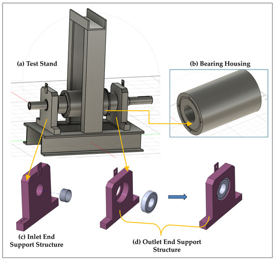
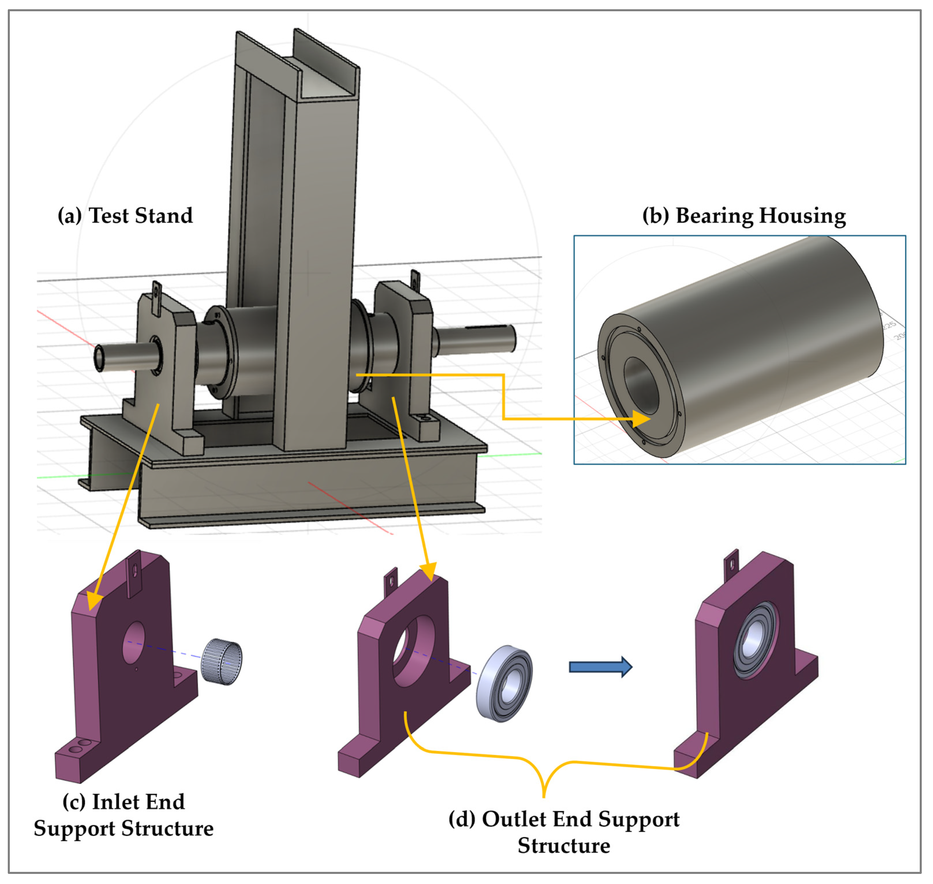
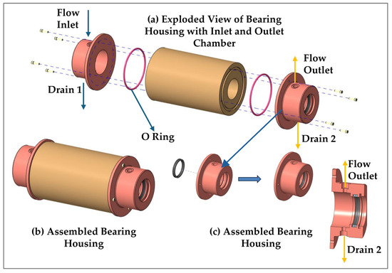
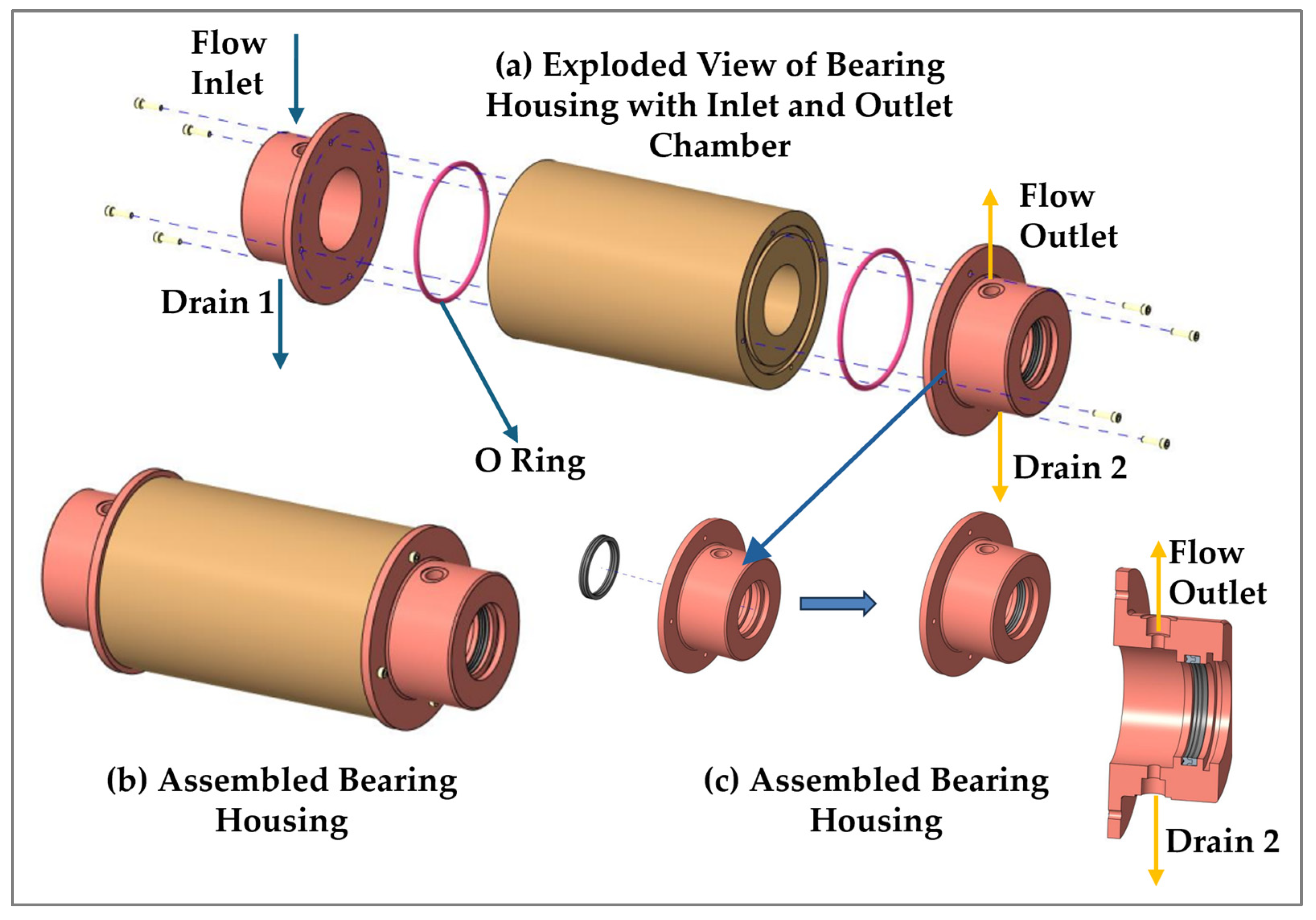
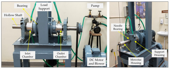
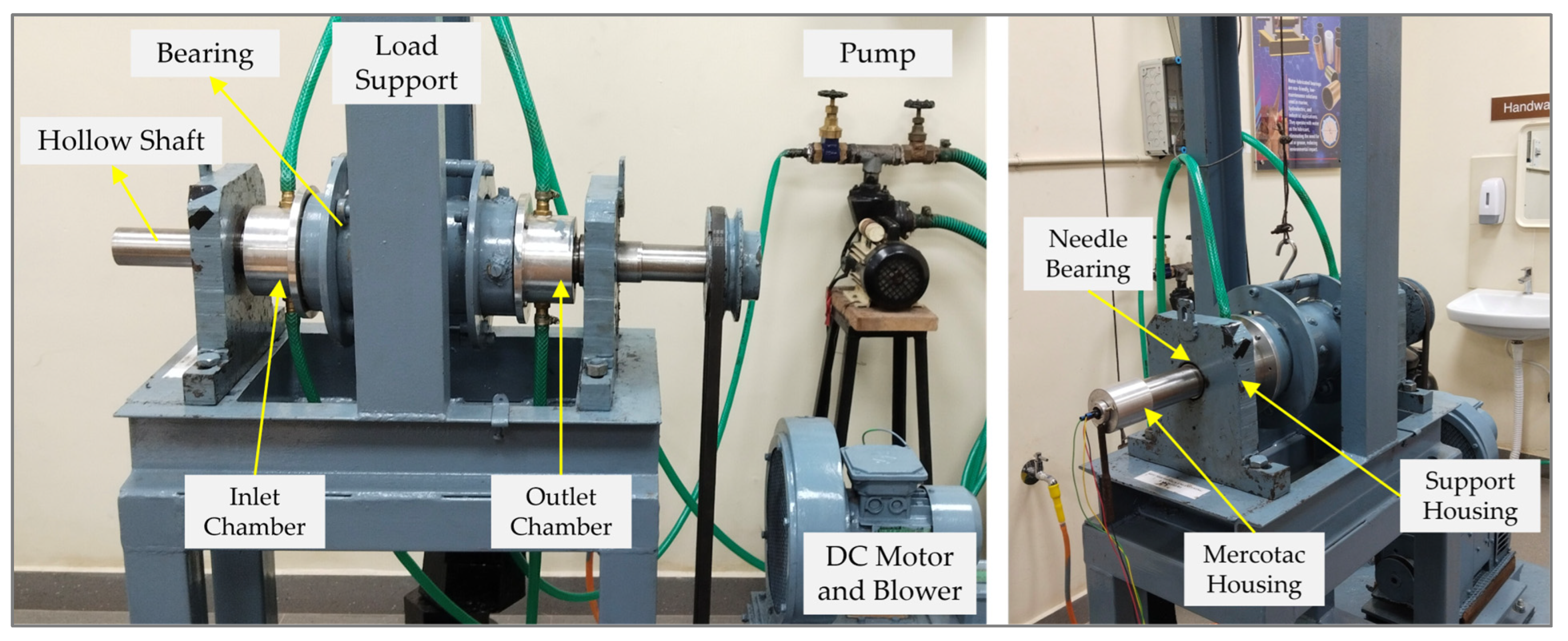
The experimental test setup shown in Figure 1, Figure 2 and Figure 3 was renovated and modified to simulate the actual operating conditions of a water-lubricated stern tube bearing. Figure 1 shows the computer-aided design (CAD) model of the test setup, bearing housing and inlet and outlet chambers utilized in the test rig facility. The main test stand was built on I-beams and incorporated vertical columns to support the loading system. Two support structures at the inlet and outlet ends with rolling-element bearings were mounted on the I-beams to support and align the rotating shaft. A needle bearing was placed at the inlet-end support structure for easy assembly and disassembly of WLBs. The outlet-end support structure was equipped with ball bearings to provide stable load capacity and smooth rotation. A multi-grooved WLB was fitted inside a metal casing with inlet and outlet flow chambers mounted at either end (Figure 2). The inlet chamber had a flow inlet and a drain connection, and the outlet chamber was configured similarly. Both flow chambers were redesigned by adding a lip seal and slid ring to prevent water leakage, which was a major issue in the earlier setup. Additionally, O-rings were placed on both ends of the bearing housing to ensure proper sealing with the flow chambers and minimize the flow leakage.
Figure 1.
CAD model of renovated water-lubricated test setup. (a) Test stand; (b) bearing housing; (c) inlet end support structure; (d) outlet end support structure.
Figure 2.
CAD model of water-lubricated bearing housing with flow chambers. (a) Exploded view of bearing housing; (b) assembled bearing housing; (c) assembled bearing housing.
Figure 3.
Experimental test rig of water-lubricated bearing.
Figure 3 details the experimental test rig facility with assembled bearing and flow chambers. A hollow stainless-steel shaft with an outer diameter of 63.206 mm and an inner diameter of about 30 mm was utilized in this study. The hollow shaft was primarily used to mount the pressure sensor at the central location of the bearing, ensuring accurate measurement of the pressure distribution during operation. The stainless-steel journal was precision-machined, balanced and supported between rolling-contact bearings in tight-fit housings fixed to I-section channel bases. The lubricating water entered axially through a pressurized inlet chamber, flowed through the clearance between the hollow stainless-steel journal and the bearing, circulated around the bearing, and exited through a low-pressure outlet chamber. The bearing, with a diametral clearance of 0.83 mm to allow for water absorption, had an axial length of 254 mm and an L/D ratio of nearly 4. The journal was driven via a belt–pulley mechanism by a 3.75 kW variable-speed DC motor from Integrated Electric Co.(P) Ltd., Peenya, Bengaluru, India, operating between 0 and 800 RPM and controlled by a DC speed controller. Two annular discs connected with tie rods placed on the bearing housing were used to apply loads in both upward and downward directions. A two-way pneumatic loading mechanism was utilized for applying loads with improved control and repeatability.
2.2. Test Bearing Specifications
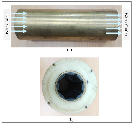
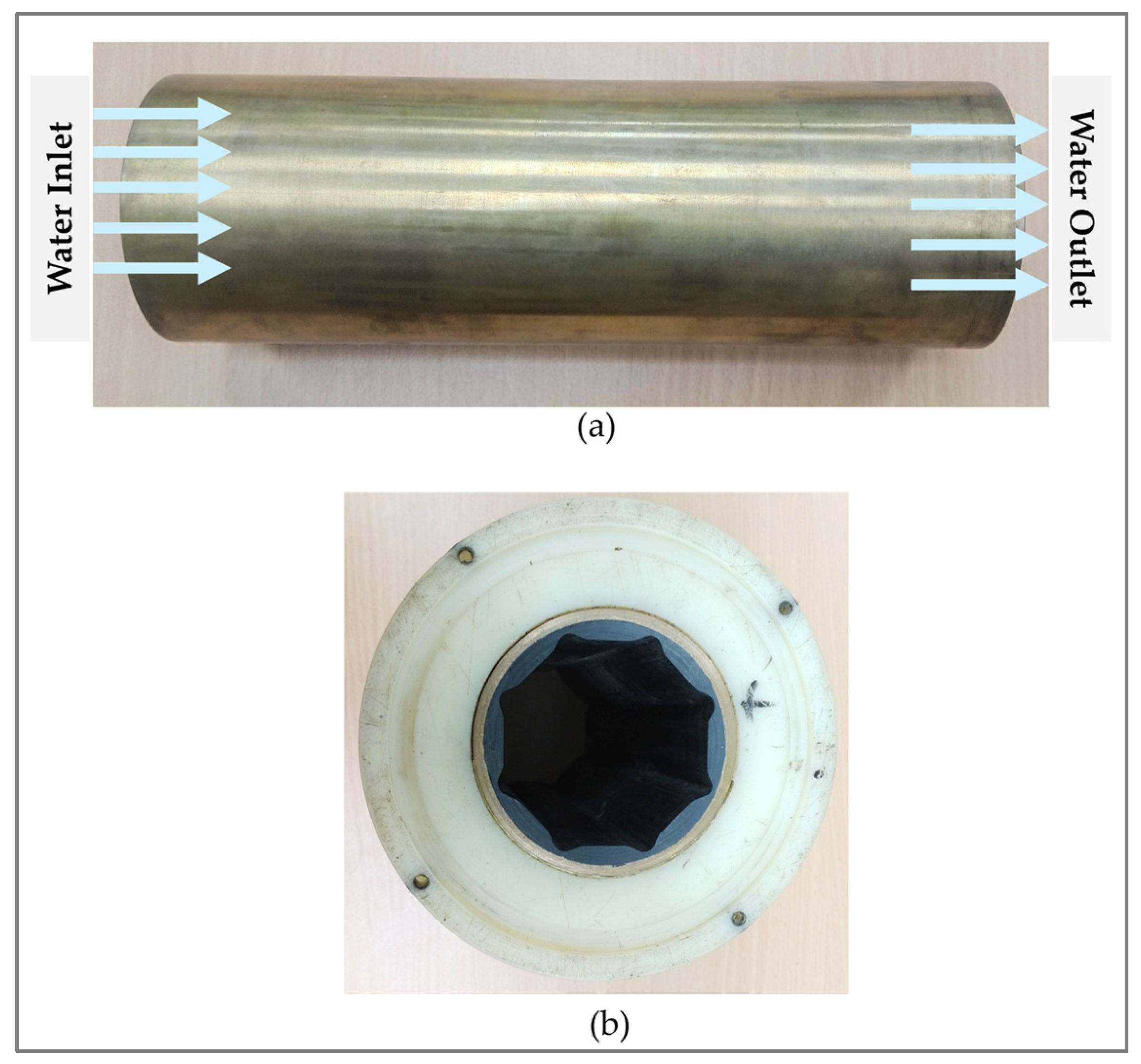
The water-lubricated bearing consisted of flexible rubber bonded to a rigid metal shell, with eight land regions (staves) and eight axial grooves (flutes). The internal geometry of the oil groove had a filleted V-shaped design. As shown in Figure 4, the bearing was press-fitted into a mild steel housing. Water flowed from the inlet chamber into the grooves, and during hydrodynamic action, the water gradually filled in the land regions before exiting through the outlet end.
Figure 4.
Water-lubricated journal bearing and flow mechanism. (a) Flow through grooves; (b) multi-grooved water-lubricated bearing with casing.
2.3. Pneumatic Loading System
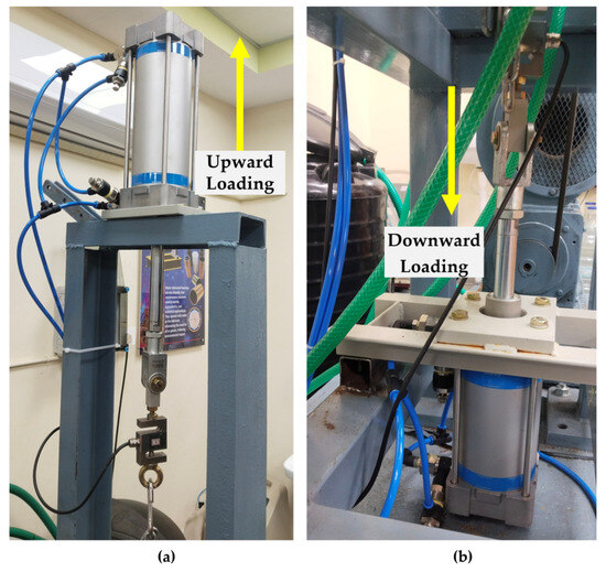
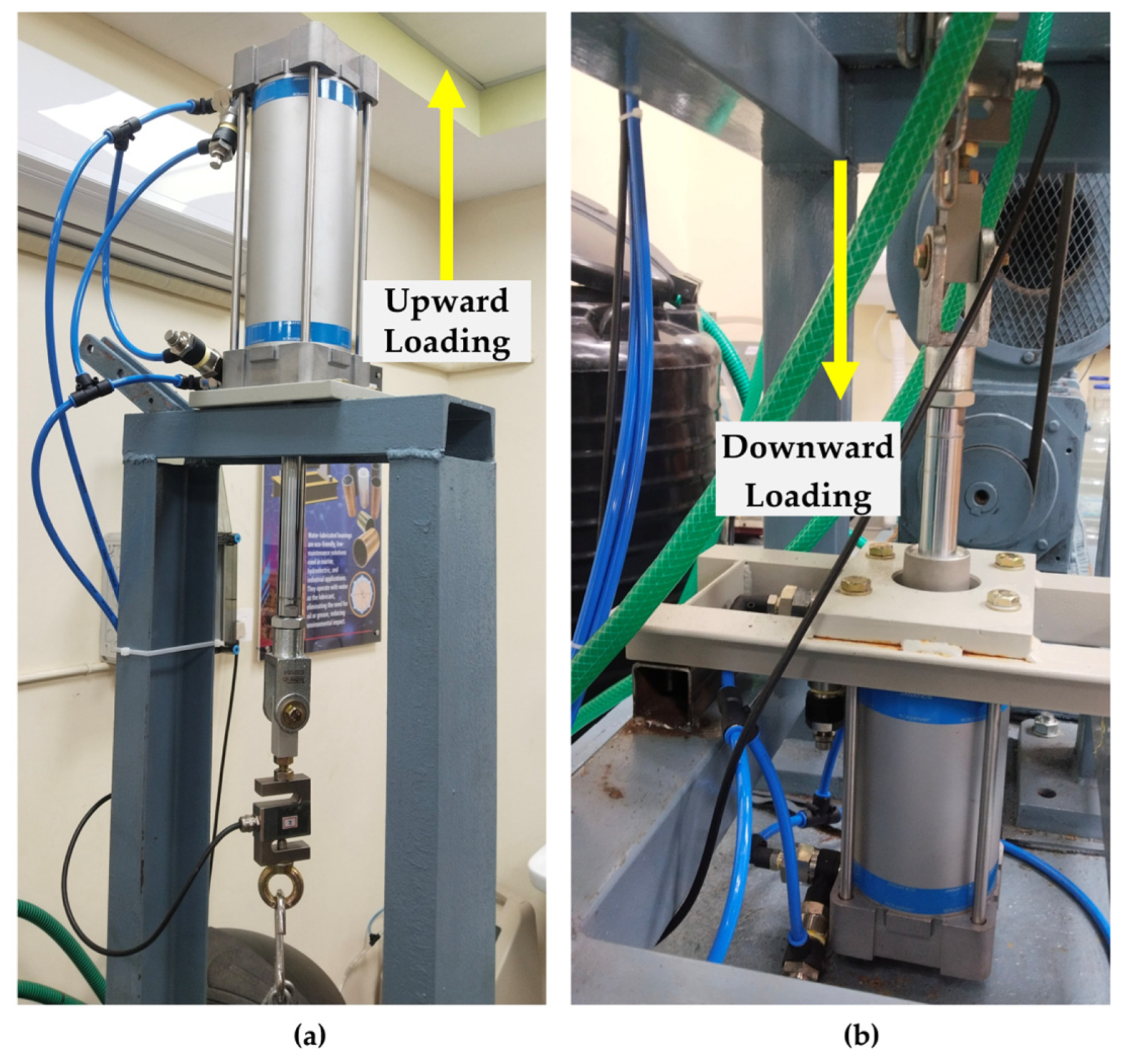
The experimental setup employed two Janatics pneumatic cylinders (Model A281002000), widely used for precision actuation in laboratory loading systems (Figure 5). The cylinder was equipped with high-quality pneumatic connectors at both the top and bottom ports, allowing controlled air supply for extension and retraction. These ports were fitted with push-in tube fittings and adjustable flow-control valves that regulated airflow and thereby fine-tuned the piston speed. The robust aluminum body, guide rods, and rigid mounting frame ensured stable vertical actuation during testing. Together, the cylinder and its end-mounted connectors enabled smooth, repeatable, and precisely controlled loading, making the unit a reliable actuator for experimental force application tasks.
Figure 5.
Pneumatic loading system for WLBs. (a) Upward Loading Cylinder (b) Downward Loading Cylinder.
2.4. Lubrication System
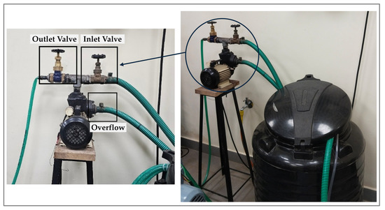
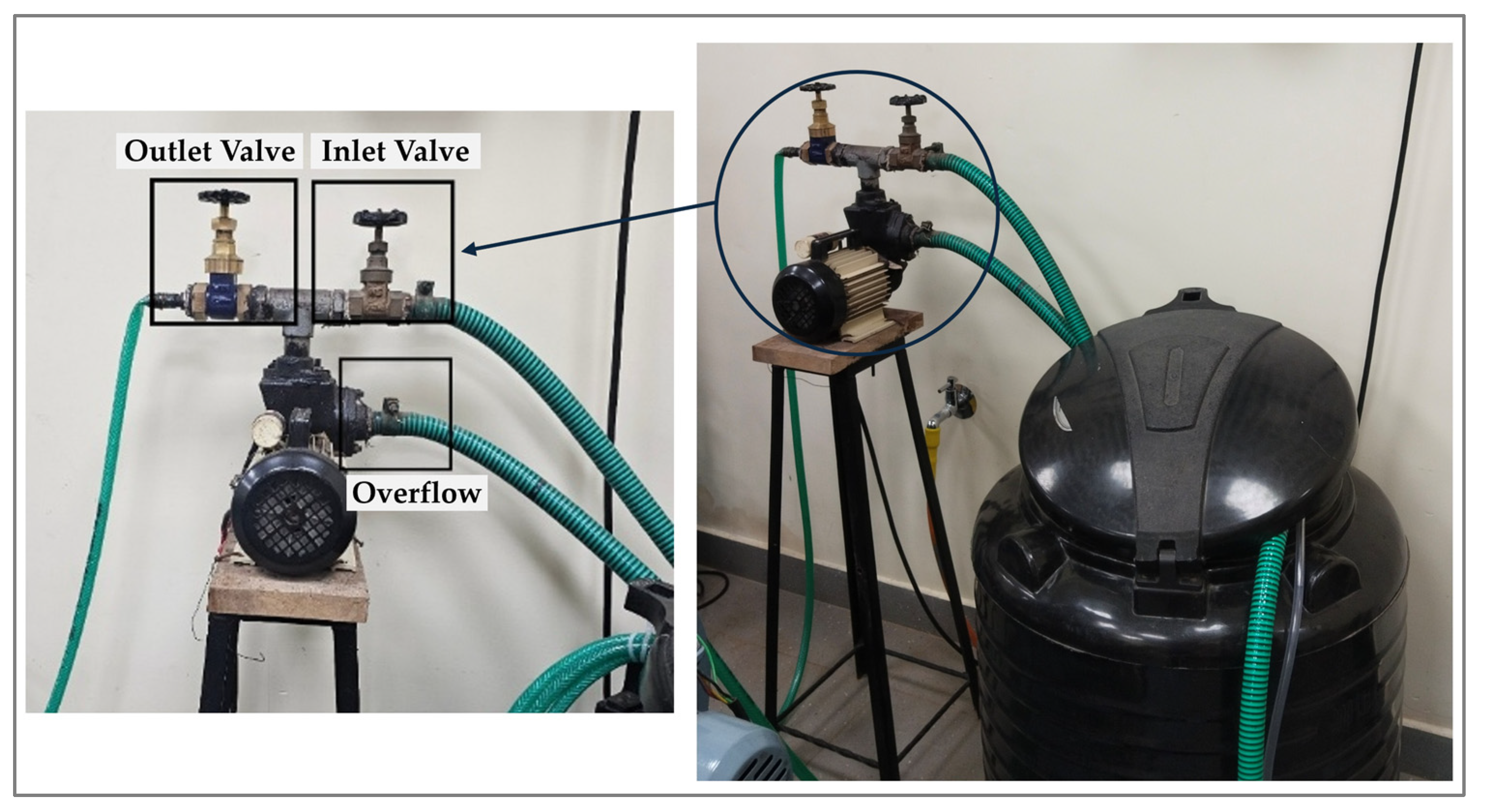
The test setup functioned as a closed-loop lubrication system in which water was pumped from a 200 L storage tank (Figure 6) into the inlet chamber of the test bearing using a centrifugal pump. A control valve at the pump outlet regulated the flow rate, while excess lubricant returned to the storage tank through a back-pressure line. The lubricant flowed from the inlet chamber through the bearing clearance and grooves, exited into the outlet chamber, and then returned to the tank via flexible pipes. Lip seals were provided at both chambers to minimize leakage at the journal interface.
Figure 6.
Water lubrication system for WLBs.
2.5. Instrumentation Setup
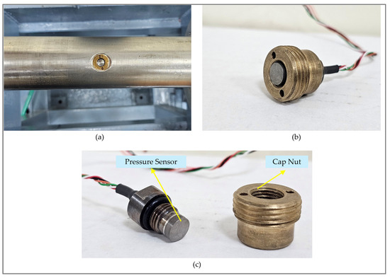
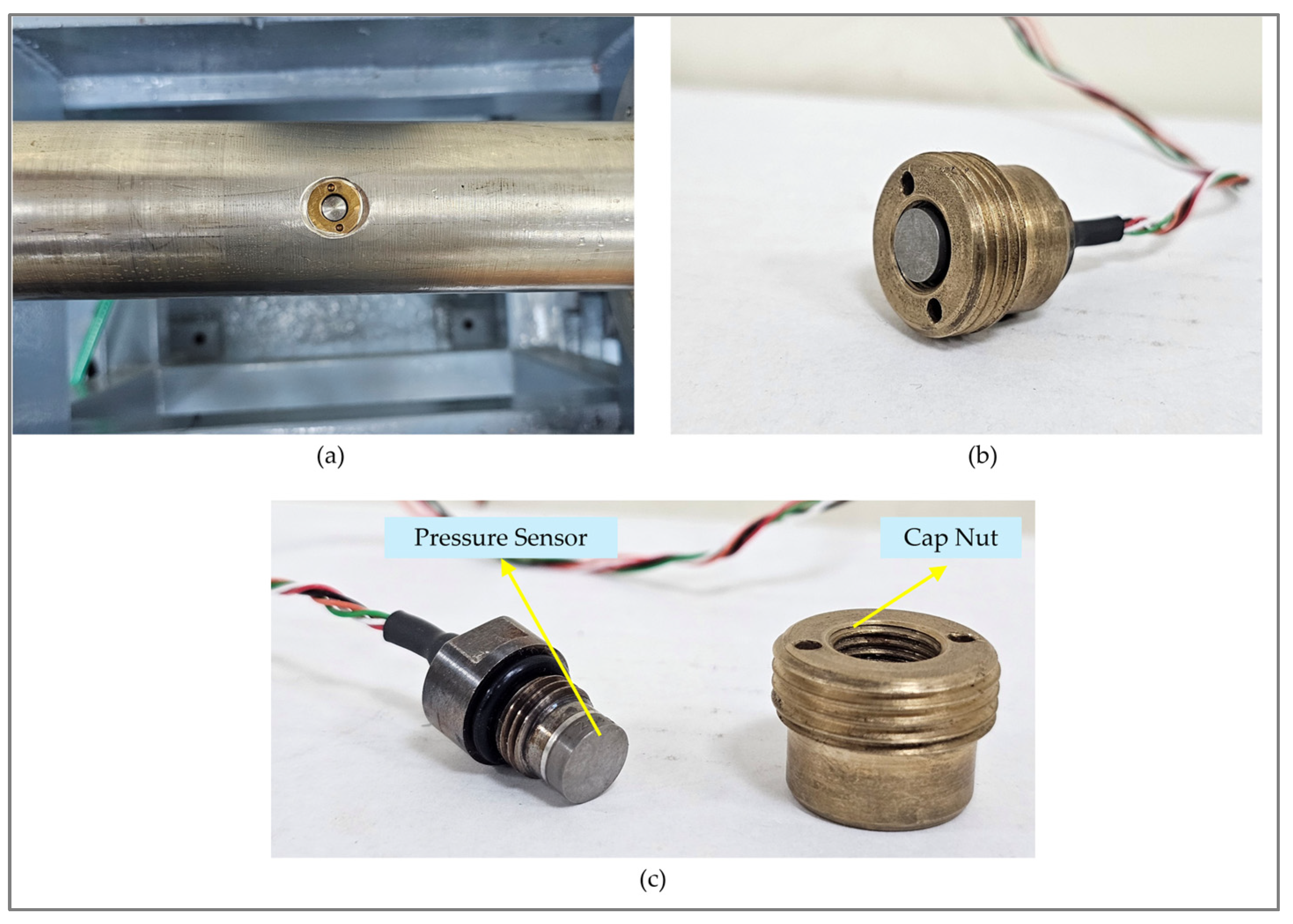
A submersible flush-type diaphragm pressure transducer (Honeywell Model S pressure sensor) was mounted on the journal to measure the hydrodynamic pressure generated at the bearing’s central plane. The sensor was positioned with its sensing surface slightly recessed below the shaft surface to ensure direct contact with the lubricant film within the clearance space. The shaft was drilled to accommodate a cap nut shown in Figure 7a, which positioned the sensor at the midpoint of the bearing. The designs of the cap nut and sensor type suitable for such bearing studies are illustrated in Figure 7b,c. The pressure sensor mounted on the rotating hollow shaft continuously measured and recorded the hydrodynamic film pressure generated within the lubricant film. The measurements were dynamically captured at the bearing mid-plane, reflecting the pressure distribution as the journal operated under rotation. This arrangement allowed for the assessment of both transient and steady-state pressure variations in the fluid film, offering valuable insights into lubrication behavior, load-carrying capacity, and overall bearing performance. Such detailed pressure measurements for realistic groove geometries are rarely reported in the existing literature and provide valuable experimental validation for numerical studies.
Figure 7.
Test journal. (a) Hollow shaft with cap nut; (b) design of cap nut; (c) flush diaphragm pressure sensor.
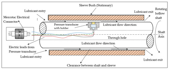
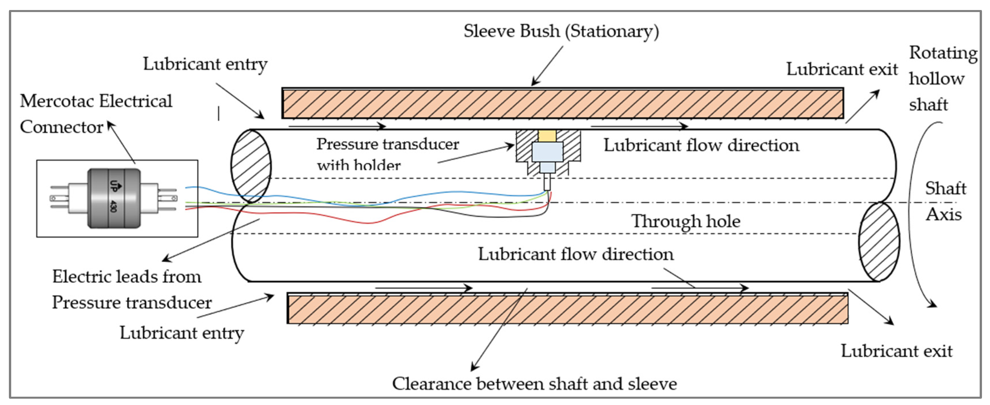
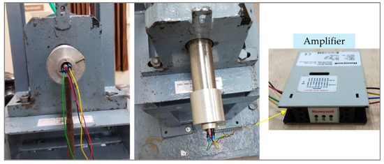
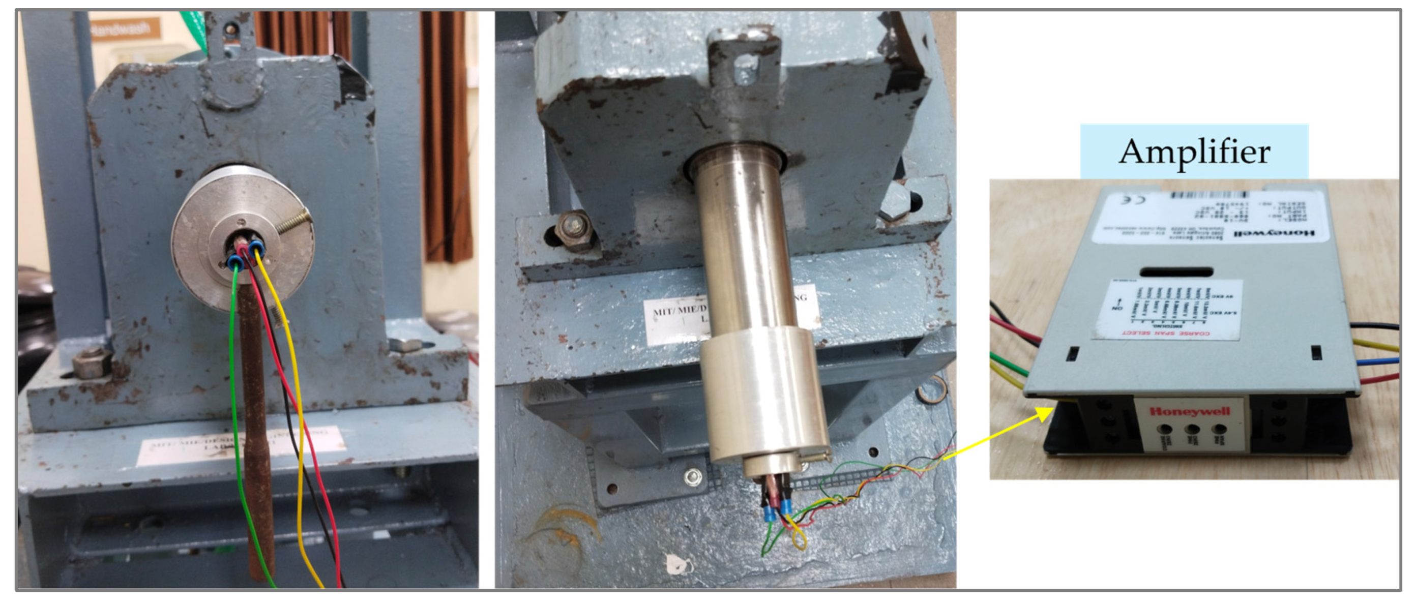
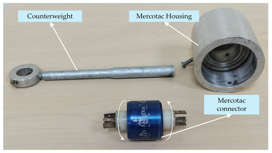
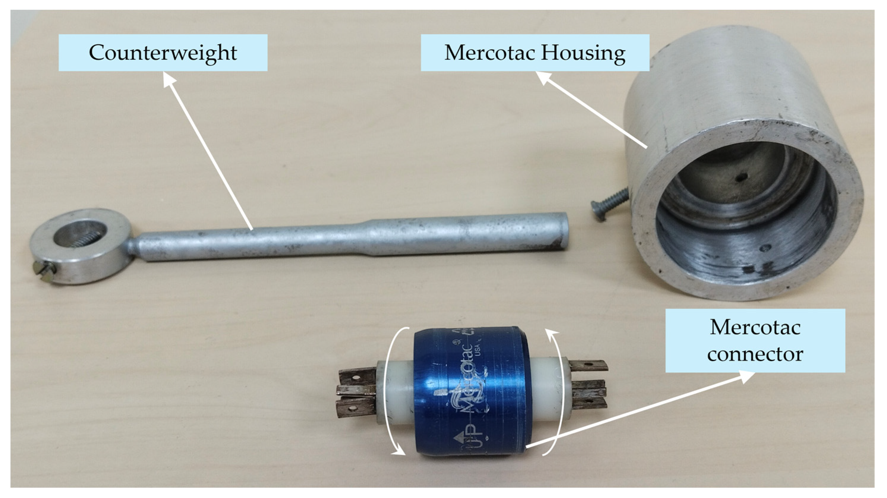
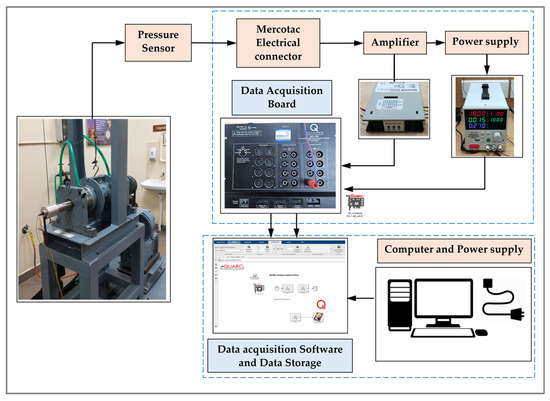
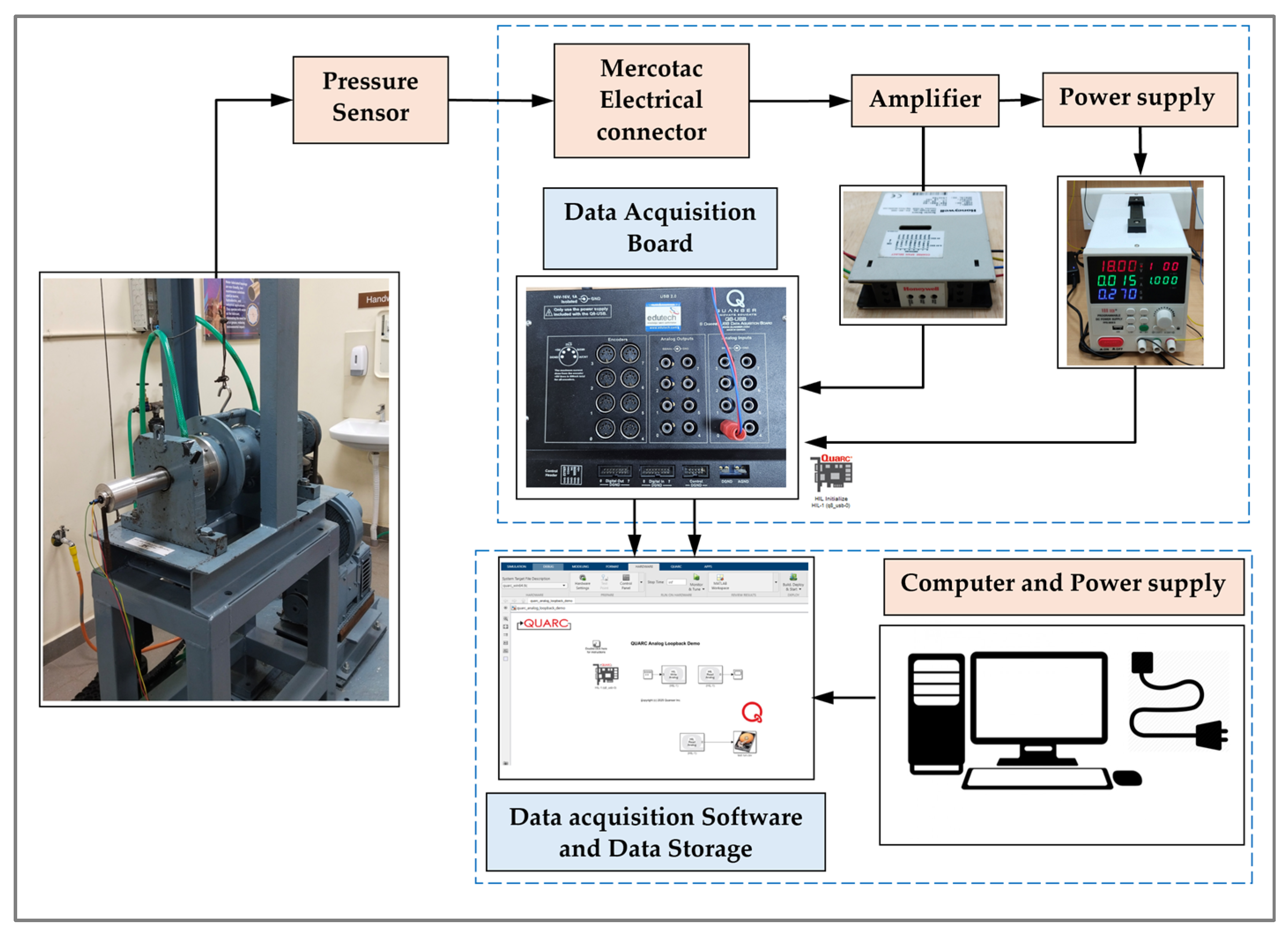
The pressure sensor used in this study had two excitation terminals and two output terminals, providing an output in mV/V. Since this output level is insufficient for direct data acquisition, the sensor signals were routed to a signal-conditioning amplifier requiring a minimum supply voltage of 18–32 V. Directly wiring the rotating sensor to the stationary amplifier is impractical, as shaft rotation would cause the wires to twist and eventually damage the sensor. To overcome this, a Mercotac rotary electrical connector was employed. Figure 8 shows the arrangement of the pressure sensor on the rotating shaft together with the Mercotac rotary connector assembly. The configuration highlights the mounting of the pressure sensor for hydrodynamic film pressure measurement, while the Mercotac connector ensured a stable and uninterrupted electrical connection for data transmission during shaft rotation. This connector had one end that rotated with the shaft, while the other end remained stationary. The sensor leads were connected to the rotating end of the Mercotac connector, allowing continuous electrical transmission without twisting sensor cables (Figure 9). The connector was housed within a custom-fabricated aluminum casing so that both the housing and the rotating end of the Mercotac rotated together with the shaft (Figure 10). The stationary end of the connector was positioned outside the shaft and secured with a counterweight to minimize residual rotation. The Mercotac electrical connector transferred the signal from the rotating sensor to an inline amplifier, which boosted the millivolt output to a voltage level suitable for acquisition. The amplifier, powered by a regulated DC supply delivering 18–32 V, was connected to a Q8 data acquisition (DAQ) board (Quansar make) operated via QUARC software 2022 (4.2.3782). The acquired voltage data were recorded on a computer and converted to pressure values (MPa) using the manufacturer-supplied calibration sheet.
Figure 8.
Pressure sensor arrangement and Mercotac working mechanism with connectors.
Figure 9.
Mercotac arrangement on hollow shaft with output wires further connected to amplifier (indicated by Yellow Arrow).
Figure 10.
Parts of Mercotac connector operation.
The schematic layout of the complete instrumentation from the bearing and pressure sensor through the Mercotac rotary connector and inline amplifier to the data acquisition (DAQ) board is shown in Figure 11. A QUARC-based MATLAB 2021b interface was developed to control and monitor the acquisition process, incorporating an HIL Initialize block for Q8 DAQ hardware configuration, signal generator blocks for generating test inputs, an HIL Write Analog block for transmitting signals to DAQ output channels, an HIL Read Analog block for acquiring analog voltages from the pressure sensor via the amplifier, and Scope blocks for real-time visualization (Figure 11). This interface enabled real-time monitoring, signal logging, and post-processing, with seamless MATLAB integration for numerical computation, signal filtering, and data analysis, thereby ensuring synchronized acquisition of pressure and displacement data for accurate correlation between operating conditions and measured film pressure. The data captured from the pressure sensor is displayed in the scope block of the MATLAB interface, with the variations visualized and recorded in real time.
Figure 11.
Layout of the instrumentation used in the experimental test setup.
3. CFD Study of Multi-Grooved Water-Lubricated Bearings
3.1. Governing Flow Equations
In a water-lubricated journal bearing, the eccentric position of the rotating shaft relative to the bearing liner produces a circumferentially varying lubricant film thickness. This geometric asymmetry results in the formation of a converging clearance zone, within which hydrodynamic pressure is generated and supports the applied radial load. The lubricant flow is described using the three-dimensional, transient conservation equations for an incompressible Newtonian fluid. The general form of the mass conservation equation is given by Equation (1).
Since the lubricant is water and density variations are negligible under the operating conditions considered, the flow is assumed to be incompressible. Accordingly, the continuity equation reduces to
Under this incompressibility constraint, the governing momentum equations take the form
These equations are solved numerically using a finite-volume-based discretization approach. The lubricant is assumed to be isothermal, iso-viscous, and fully flooded throughout the bearing clearance and axial groove regions. At the start of the transient simulation, the lubricant within the computational domain is initialized at rest with a uniform reference pressure. Accordingly, the initial velocity field is set to zero in all directions, and the pressure field is initialized to ambient pressure.
3.2. Turbulence Modeling and Numerical Implementation
At high rotational speeds, the lubricant flow within the bearing clearance may transition to a turbulent regime. To account for this effect, a shear-stress-transport (SST) turbulence model is employed, as it provides improved near-wall resolution while retaining numerical stability in the core flow region.
The transport equation for turbulent kinetic energy is given by
Similarly, the specific dissipation rate is governed by
where and represent the turbulence production, and denote the dissipation terms, and accounts for cross-diffusion effects. The turbulence variables are initialized with low uniform values corresponding to a low turbulence intensity at the beginning of the simulation to ensure numerical stability. The transient solution is advanced in time until a periodic steady-state condition is achieved, after which the pressure and velocity fields reported in this study are extracted.
3.3. CFD Model of WLBs
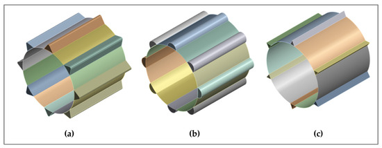
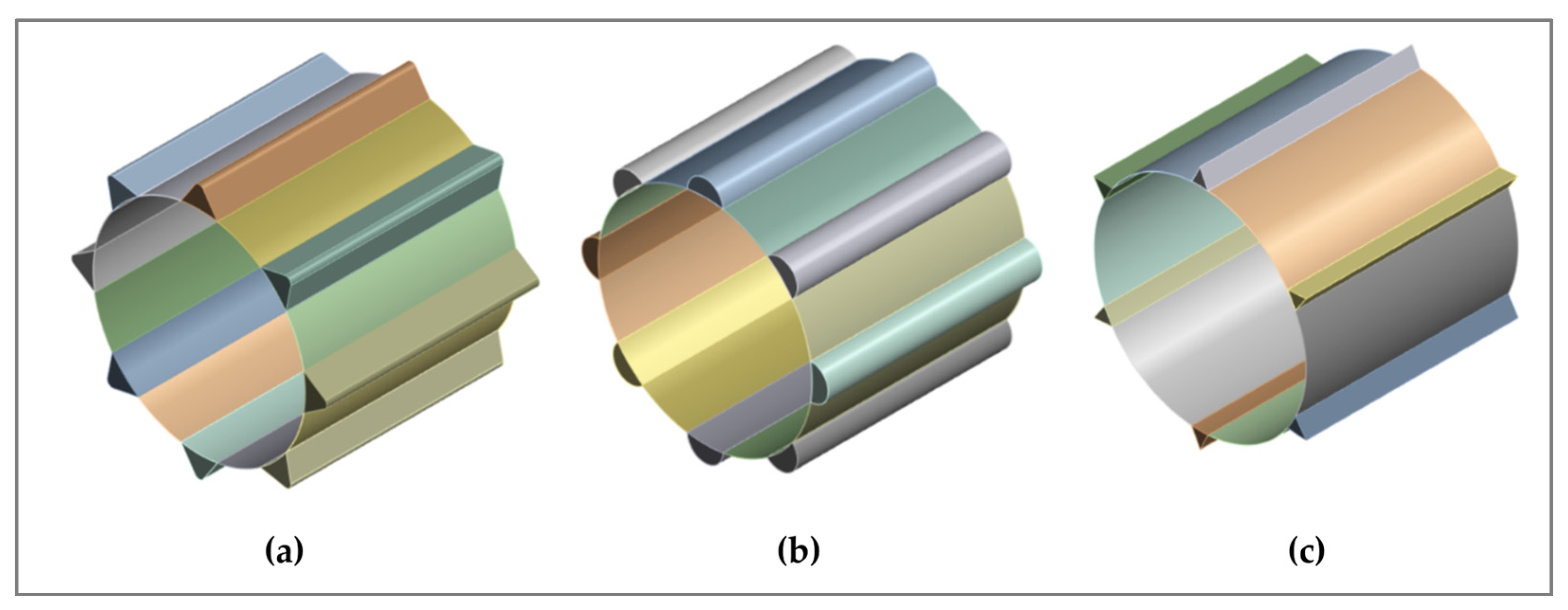
A three-dimensional computational model was first developed to characterize hydrodynamic pressure generation in water-lubricated bearings (WLBs), incorporating specific axial groove geometries and profile variations. In contrast with earlier numerical investigations that primarily adopt simplified or idealized groove representations, the present CFD model incorporates realistic groove geometries and operating conditions consistent with the experimental configuration. This approach enables a closer representation of actual bearing behavior and facilitates direct comparison between experimental observations and numerical predictions. The bearing configuration with length-to-diameter ratios of 1.0 was analyzed over a rotational speed range of 400–6000 RPM. As illustrated in Figure 12, three axially grooved bearing geometries, namely, filleted V-shaped grooves, semicircular grooves, and short V-shaped grooves, each incorporating eight equally spaced grooves along the axial direction, were considered as test configurations. The filleted V-shaped groove model features smoothly rounded groove edges, while the short V-shaped groove model incorporates truncated V-shaped profiles. In contrast, the semicircular groove configuration provides a uniform groove cross-section that promotes consistent lubricant distribution. These models enable a systematic assessment of the influence of groove geometry on pressure development, flow characteristics, and overall bearing performance under water-lubricated conditions. The computational analysis was executed using the dynamic mesh model in ANSYS Fluent (ANSYS 2025R1) to resolve the flow field evolution. The journal eccentricity ratio was imposed as a fixed geometric constraint derived from steady-state operating conditions, with the journal center coordinates initialized such that the line of centers coincided with the vertical axis. Consequently, the equilibrium attitude angle was determined through post-processing of the converged solution. The orthogonal components of the generated hydrodynamic force were integrated over the journal surface to compute the resultant load vector. The operating attitude angle was then defined as the angular deviation of this resultant force vector relative to the vertical axis. The computational domain was discretized using a structured mesh with enhanced near-wall resolution to accurately resolve velocity and pressure gradients within the thin lubricant film. Steady-state solutions were obtained after ensuring convergence of residuals and stabilization of integral performance parameters.
Figure 12.
CFD models of multi-grooved water-lubricated bearings (WLB). (a) Filleted V-shaped groove; (b) semicircular groove; (c) short V-shaped groove.
3.4. Mesh and Boundary Conditions
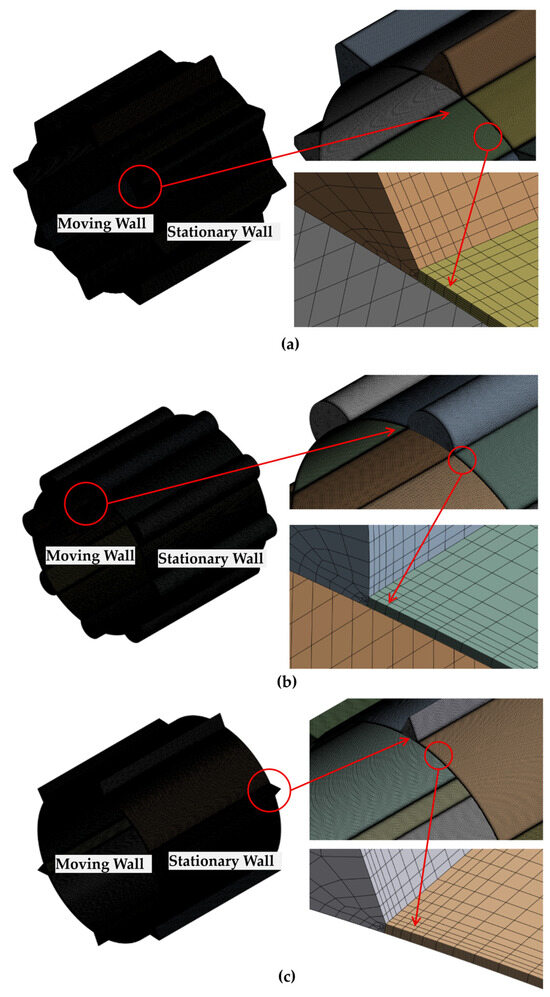
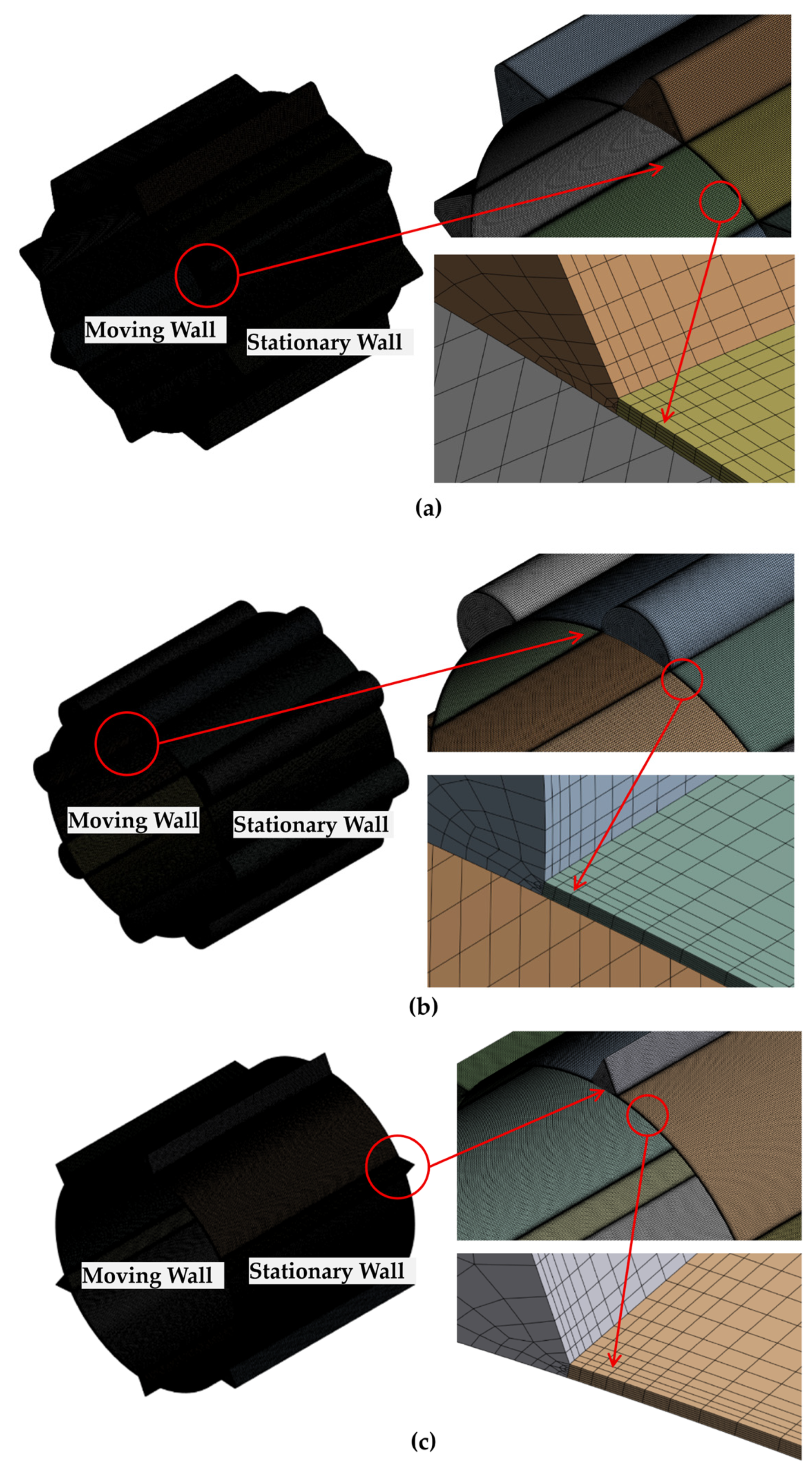
Figure 13 illustrates the mesh topology employed for the fluid domain of the axially grooved water-lubricated bearings (WLBs). To accurately evaluate the hydrodynamic lubrication performance, a carefully optimized spatial discretization strategy was developed. Considering the inherent trade-off between computational cost and numerical accuracy, a non-uniform meshing approach was adopted. Instead of uniformly increasing the global element count, localized mesh refinement was applied to geometrically critical regions such as groove edges, sharp topographical features, and asperity peaks. This targeted refinement ensures high numerical resolution in regions with steep velocity and pressure gradients, while avoiding unnecessary increases in the overall degrees of freedom.
Figure 13.
Mesh geometry of WLB fluid domain with multiple grooves. (a) Filleted V-shaped groove; (b) semicircular groove; (c) short V-shaped groove.
The fluid domain was discretized using a structured hexahedral mesh to enhance numerical stability and computational efficiency. Groove boundaries were partitioned to maintain strict control over mesh orthogonality and element aspect ratios. A multizone meshing strategy was employed for volume discretization, combined with a sweep method to preserve axial mesh uniformity. To improve the accuracy of hydrodynamic pressure predictions, refined inflation layers were introduced along the fluid–solid interfaces, thereby minimizing discretization errors associated with boundary layer modeling. Within the bearing land regions, the fluid domain was further refined using five inflation layers to accurately resolve near-wall hydrodynamic phenomena. This refinement is essential for capturing thin-film lubrication effects and for resolving sharp velocity and pressure gradients adjacent to the solid boundaries. By ensuring adequate mesh resolution within the viscous sublayer, the numerical model reliably represents boundary layer characteristics, thereby enhancing the robustness of the CFD simulations and the fidelity of the predicted lubrication film behavior.
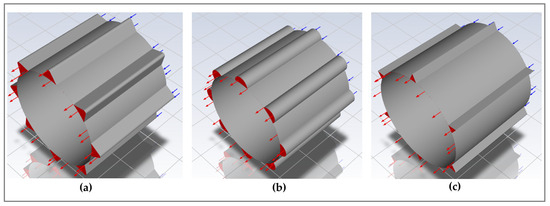
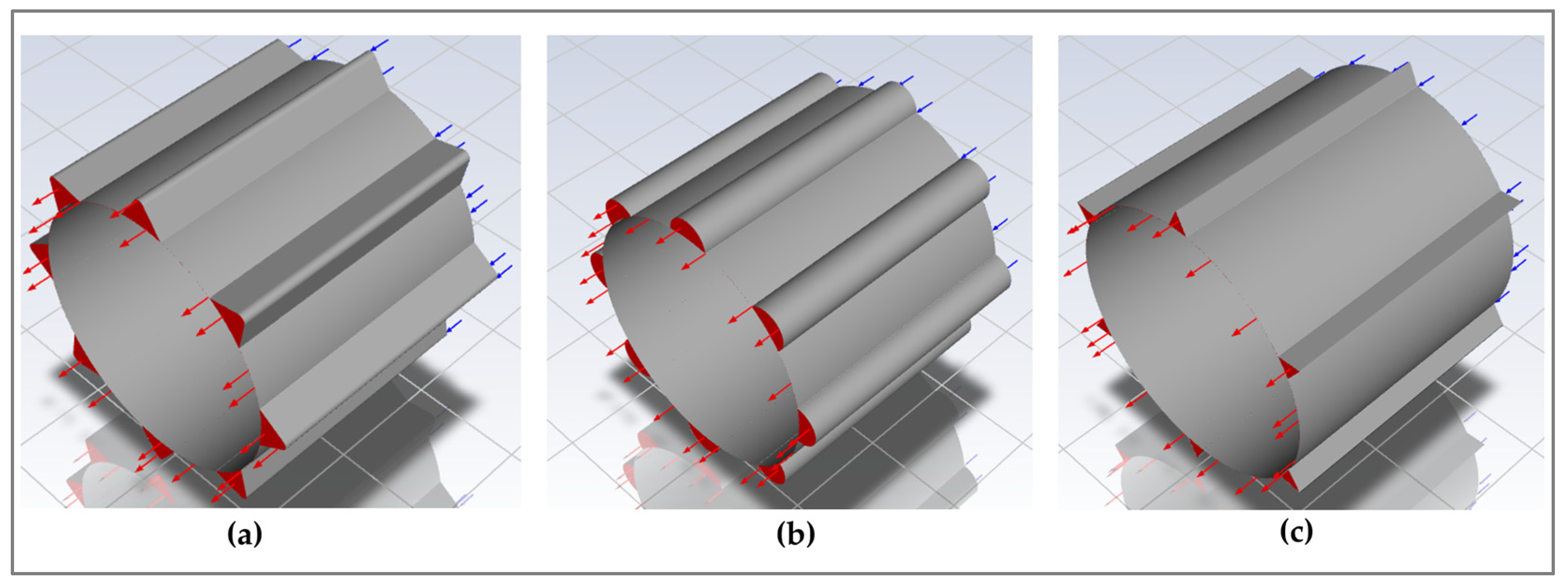
The boundary conditions applied to the CFD models are illustrated in Figure 14. The inlet and outlet of the lubricant film were positioned on opposite sides of the bearing clearance to represent an open-ended water-lubricated bearing configuration. At both the inlet and outlet boundaries, a gauge pressure of 0 Pa was prescribed, corresponding to ambient pressure conditions and allowing free inflow and outflow of the lubricant. The outer surface of the water film, corresponding to the stationary bearing liner, was modeled as a fixed wall with a no-slip boundary condition. The inner surface, representing the rotating journal, was also treated as a no-slip wall and assigned the prescribed rotational speed, thereby inducing shear-driven flow within the lubricant film. This wall treatment ensured accurate representation of viscous effects and momentum transfer between the rotating shaft and the lubricant. A pressure-based solver was employed for the numerical simulations, as it is well suited for incompressible flows characteristic of hydrodynamic lubrication. The pressure–velocity coupling was handled using the SIMPLEC algorithm to enhance convergence stability and computational efficiency. Steady-state solutions were obtained by iteratively solving the governing equations until both residuals and integral performance parameters satisfied the prescribed convergence criteria.
Figure 14.
Multi-grooved WLB model with boundary conditions. (a) Filleted V-shaped groove; (b) semicircular groove; (c) short V-shaped groove.
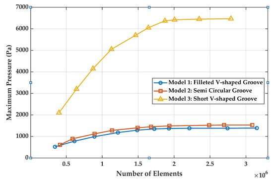
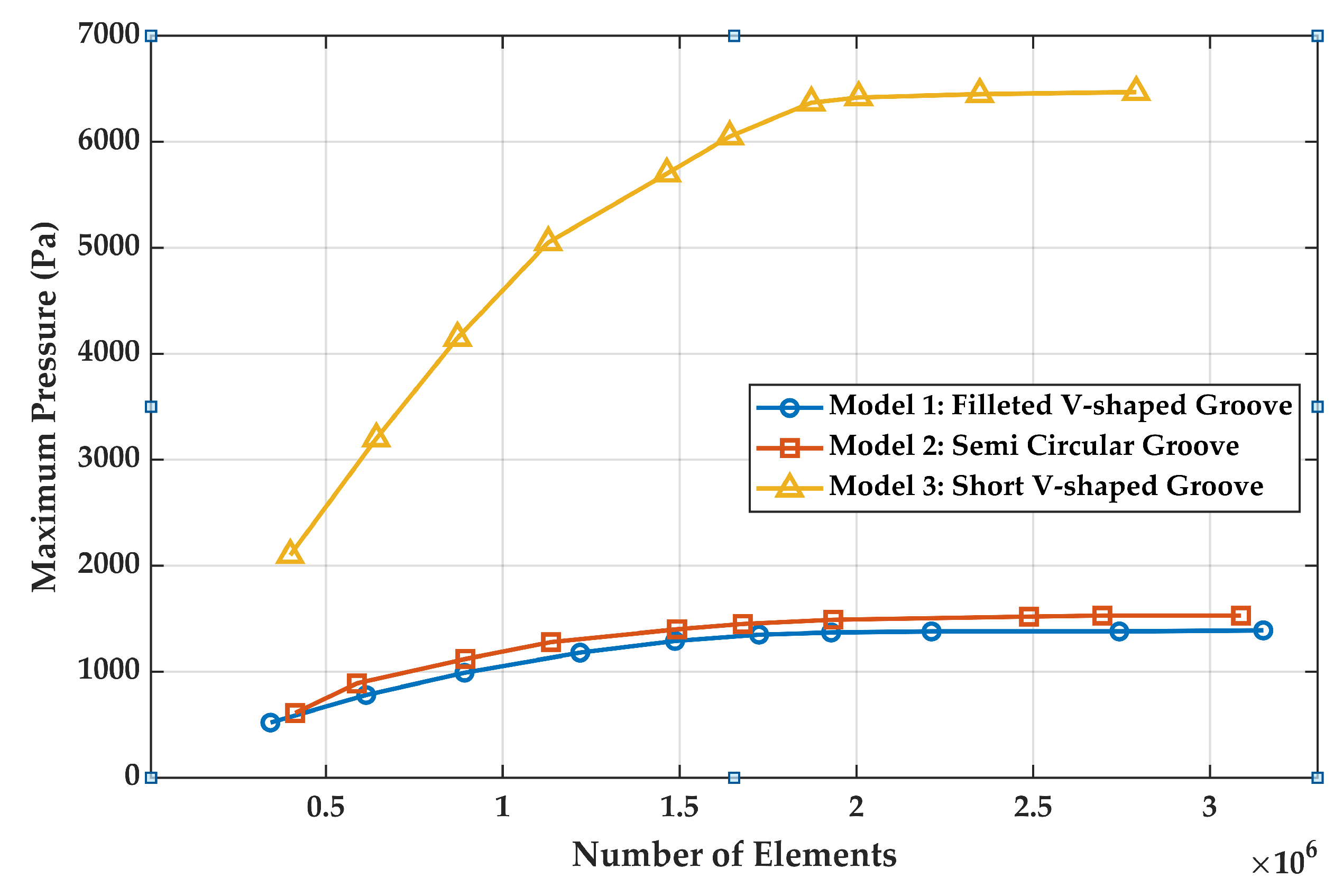
A mesh independence study was conducted to verify that the numerical predictions were not influenced by spatial discretization, as illustrated by the variation in maximum hydrodynamic pressure with increasing element count in Figure 15. Progressive mesh refinement was carried out for all three groove configurations, and the corresponding peak film pressure was monitored to assess convergence. For each bearing model, the maximum pressure increased with mesh refinement at lower element counts and then converged to a stable value, beyond which further refinement produced negligible variation. This trend confirms that the numerical solutions become mesh independent once a critical mesh density is attained. Although the short V-shaped groove model exhibited substantially higher-pressure levels than the filleted V-shaped and semicircular groove models, all configurations demonstrated similar convergence behavior. Based on this assessment, the final mesh sizes were selected to achieve an optimal balance between numerical accuracy and computational efficiency. The adopted meshes comprised 2,212,497 elements for the filleted V-shaped groove model, 2,488,472 elements for the semicircular groove model, and 2,006,315 elements for the short V-shaped groove model. These mesh densities were used for all subsequent simulations to ensure consistent and reliable hydrodynamic performance predictions.
Figure 15.
Mesh independence analysis of WLBs with different groove configurations.
4. Validation
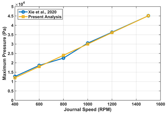
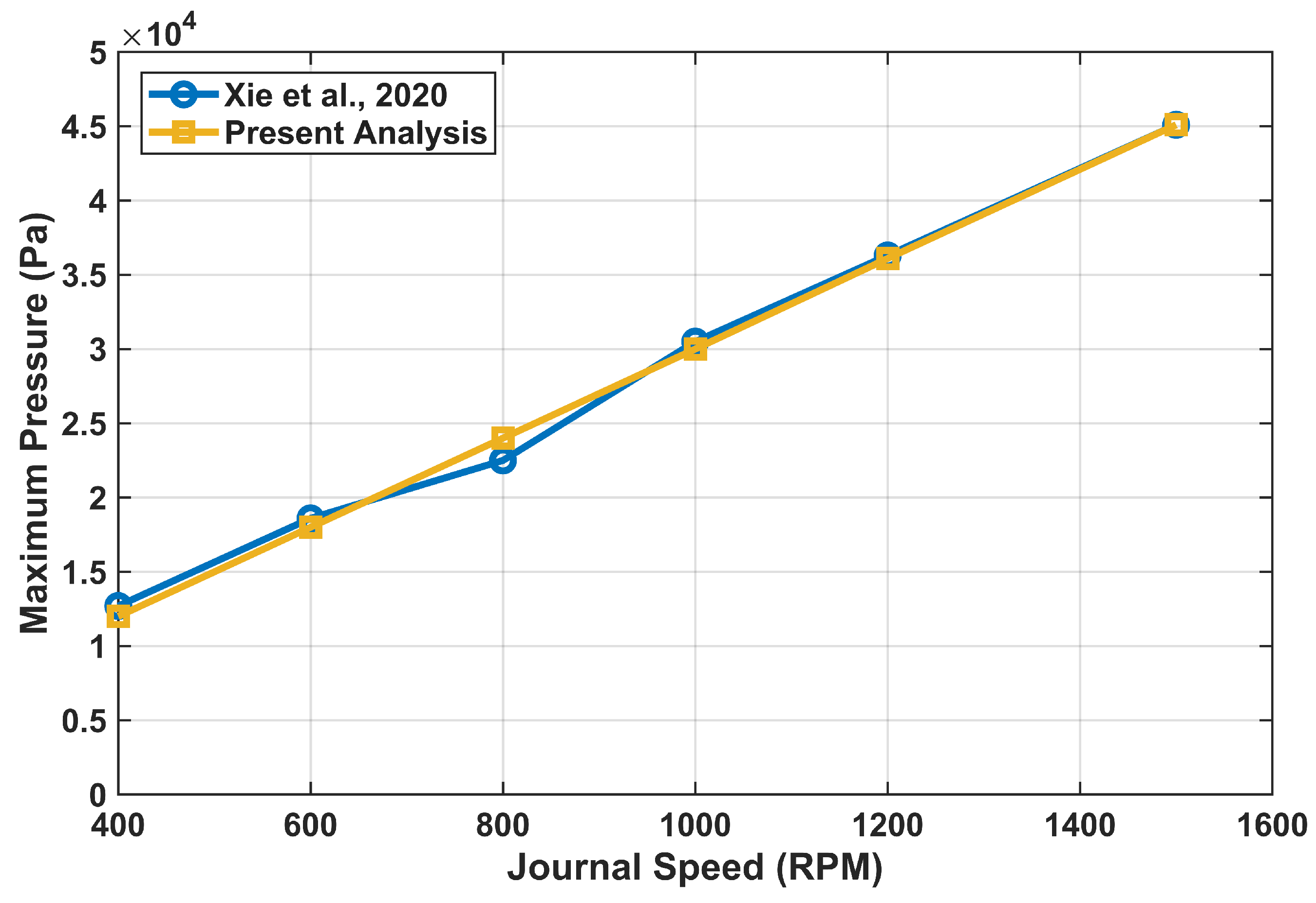
To establish the reliability of the computational framework, the CFD model was validated against the numerical results reported by Xie et al. [43] for a water-lubricated bearing operating under identical geometric and operating conditions. In the present work, validation was performed by reproducing the operating conditions corresponding to the water-lubricated bearing case reported by Xie et al. [43] with particular emphasis on the variation of maximum hydrodynamic pressure with journal speed. All relevant geometric parameters, lubricant properties, and boundary conditions were matched to the reference study. The comparison was carried out over a rotational speed range of 400–1500 RPM to assess the ability of the model to capture speed-dependent pressure development. As shown in Figure 16, the present results exhibit excellent agreement with the reference data across the entire speed range, with both datasets showing a consistent increase in maximum pressure with increasing rotational speed. The close correspondence in trend and magnitude confirmed that the numerical formulation accurately captured the underlying hydrodynamic behavior of the water-lubricated bearing. This agreement validated the adopted mesh resolution, numerical schemes, and boundary condition implementation, thereby providing confidence in the predictive capability of the CFD model. Consequently, the validated framework was considered reliable for the subsequent parametric investigation of axial groove geometry and bearing performance.
Figure 16.
Comparison of maximum pressure variation with journal speed between Xie et al.’s study [43] and the present analysis.
5. Results and Discussion
5.1. Experimental Water Film Pressure Measurements in MGWLBs
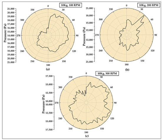
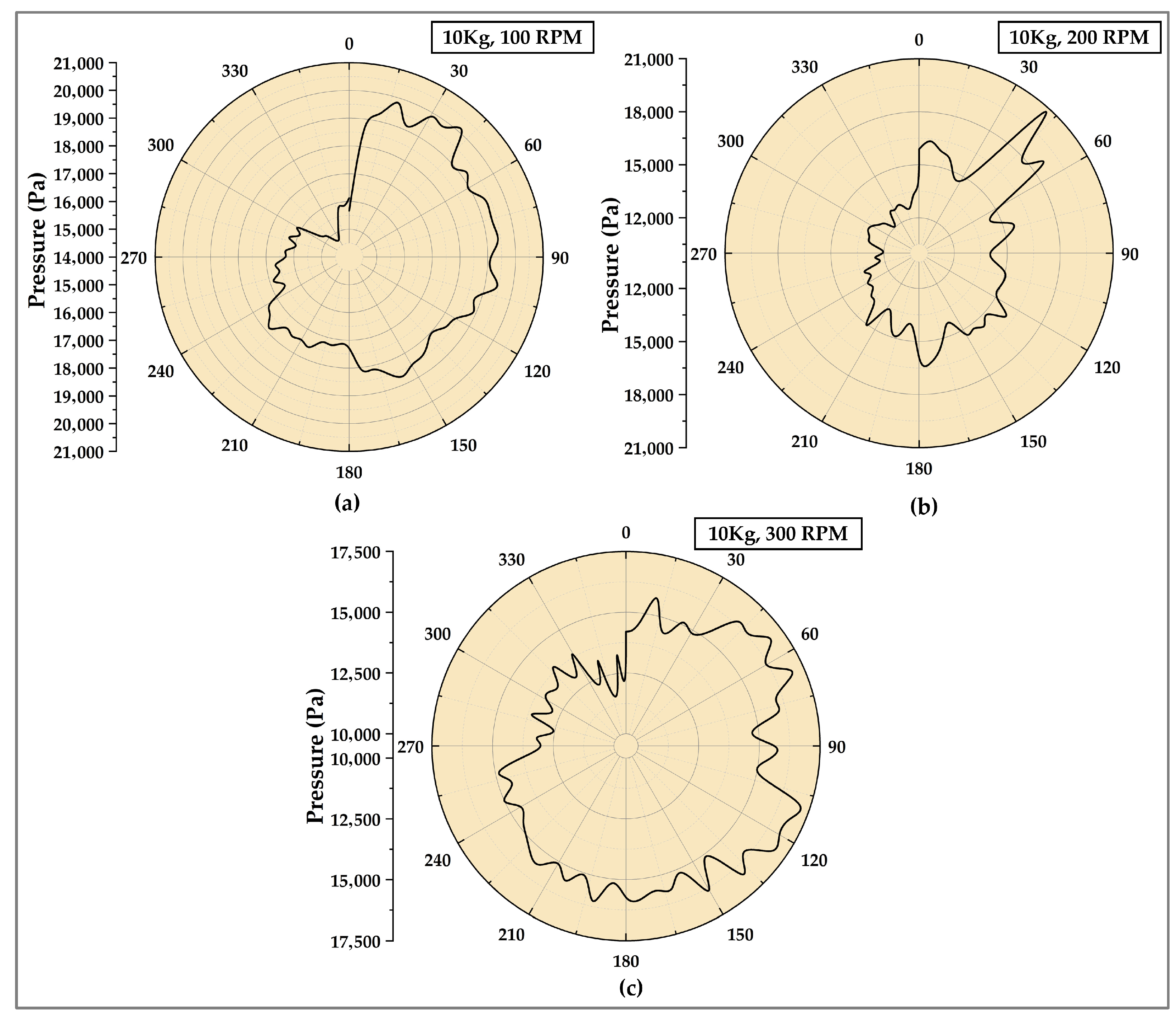
The renovated WLB test rig, which replicates the stern tube operational conditions, was utilized to conduct a series of controlled experiments to measure the circumferential hydrodynamic pressure variation under different rotational speeds and applied loads. For the experimental case, a multi-grooved WLB with filleted V-shaped grooves was tested. Figure 17 presents the circumferential film pressure distribution measured at the mid-plane of the MGWLB under a constant 10 kg upward load for rotational speeds of 100, 200 and 300 RPM. The polar plots depict the circumferential pressure variation as a function of angular position around the bearing, measured using a flush-mounted pressure sensor integrated into the rotating hollow journal. At 100 RPM in Figure 17a, the pressure profile exhibits a relatively asymmetric distribution with a well-defined pressure build-up region extending over a wider angular span. The peak pressure occurs downstream of the load line, indicating the initiation of hydrodynamic wedge formation as the journal begins to entrain water into the converging clearance. However, the overall pressure magnitude and circumferential spread remain modest, reflecting the limited hydrodynamic action at a low rotational speed where viscous shear and lubricant entrainment are comparatively weak. As the speed increases to 200 RPM (Figure 17b), a marked enhancement in the pressure magnitude is observed. The pressure distribution becomes better developed, with the high-pressure zone spreading over a concentrated angular region. Such behavior is attributed to increased journal surface velocity, which strengthens the hydrodynamic wedge effect and promotes more effective water entrainment into the land regions between grooves. The smoother pressure variation also suggests improved film stability and reduced local pressure fluctuations compared with the 100 RPM case. As shown in Figure 17c at 300 RPM, the pressure field reaches its most uniform and fully developed state. The peak pressure values have stabilized due to lesser loads acting, and the pressure contours show a broader, more evenly distributed load-supporting region. The circumferential pressure variation becomes smoother, indicating a stable hydrodynamic film. The effect of the multi-grooved geometry is clearly reflected in the pressure profiles, where periodic fluctuations correspond to transitions between land and groove regions without causing abrupt pressure drops. At elevated speeds, pressure generation is dominated by viscous-driven hydrodynamic effects, signifying stable full-film lubrication with negligible boundary contribution.
Figure 17.
Polar representation of water film pressures in MGWLB for varying speeds under 10 kg upward load. (a) 100 RPM (b) 200 RPM (c) 300 RPM.
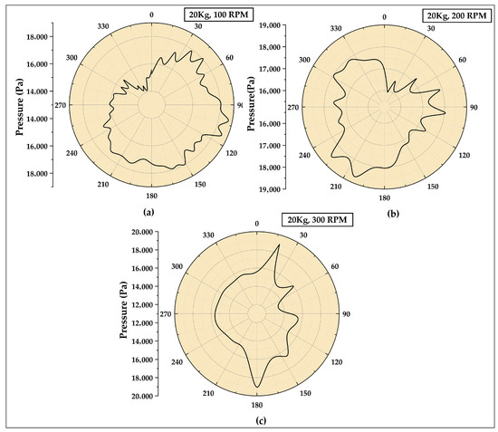
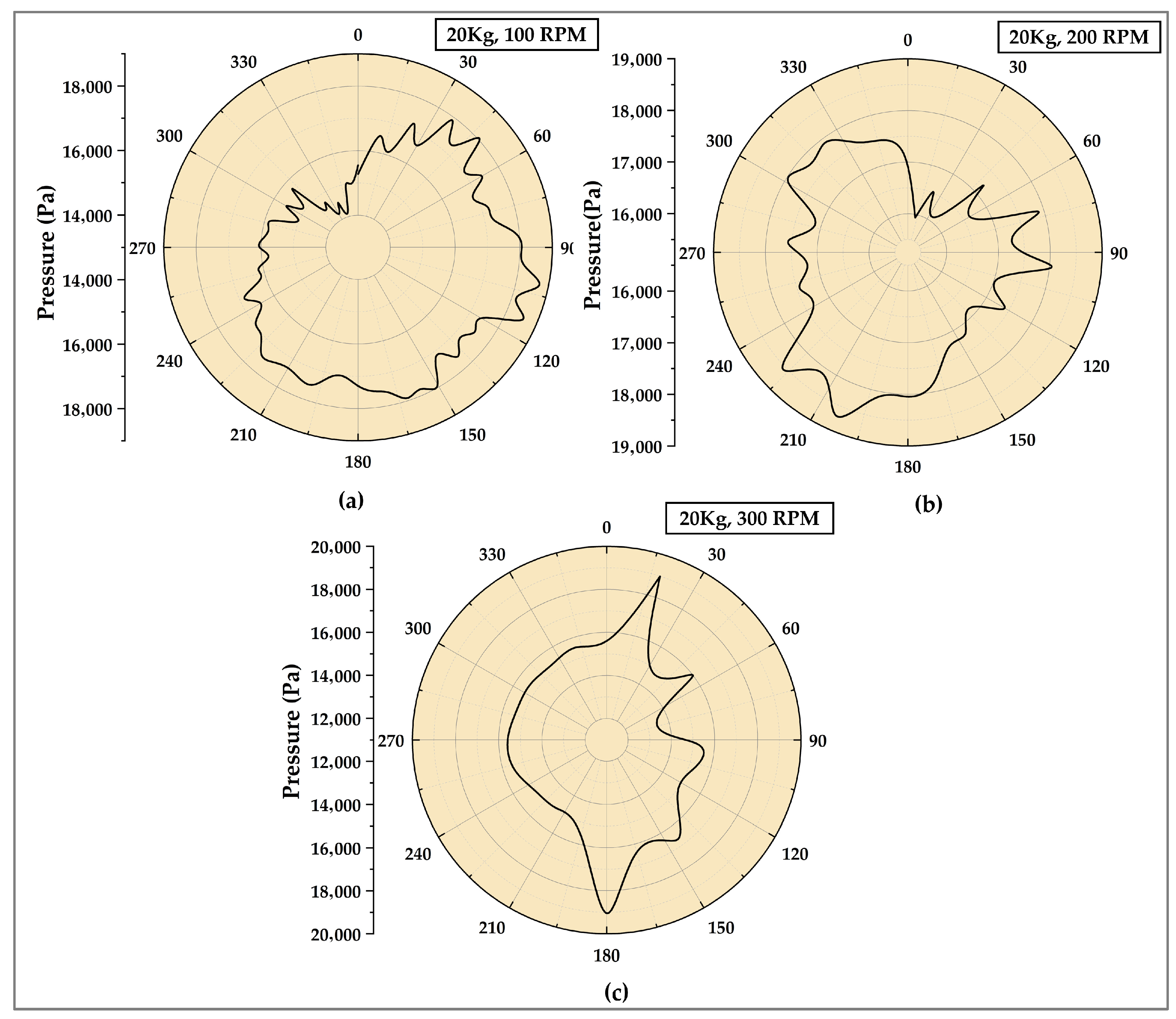
Figure 18 presents the experimentally measured water film pressure variation at the bearing mid-plane for an upward load of 20 kg. In comparison with lower loads, the pressure profiles reflect a stronger influence of applied load on film formation and pressure development across the bearing circumference. At a rotational speed of 100 RPM (Figure 18a), the pressure distribution shows a distinct but angularly limited load-carrying zone, along with pronounced circumferential non-uniformities. The confined pressure region suggests inadequate lubricant entrainment at a low speed to sustain a continuous hydrodynamic film under higher load. With an increase in speed to 200 RPM (Figure 18b), the pressure distribution expands circumferentially and becomes more coherent. The pressure field shows improved continuity and reduced asymmetry, indicating enhanced hydrodynamic action arising from increased journal velocity. This transition reflects more effective lubricant transport through the groove–land network, resulting in a broader and more stable load-carrying region. At 300 RPM, the pressure field demonstrates a broad and well-developed load-carrying region with relatively smooth circumferential variation, influenced by two pronounced localized pressure peaks, likely arising from groove–land geometric effects and local flow concentration. While periodic pressure fluctuations associated with the land–groove geometry remain visible, their influence is moderated, indicating stable full-film lubrication.
Figure 18.
Polar representation of water film pressures in MGWLB for varying speeds under 20 kg upward load. (a) 100 RPM (b) 200 RPM (c) 300 RPM.
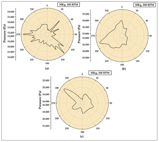
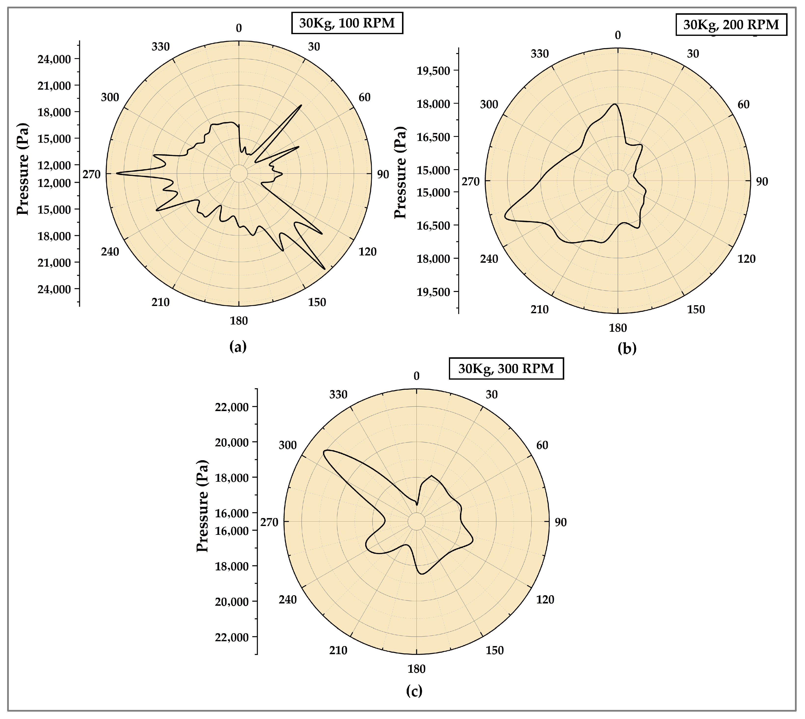
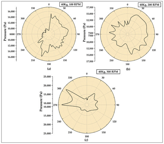
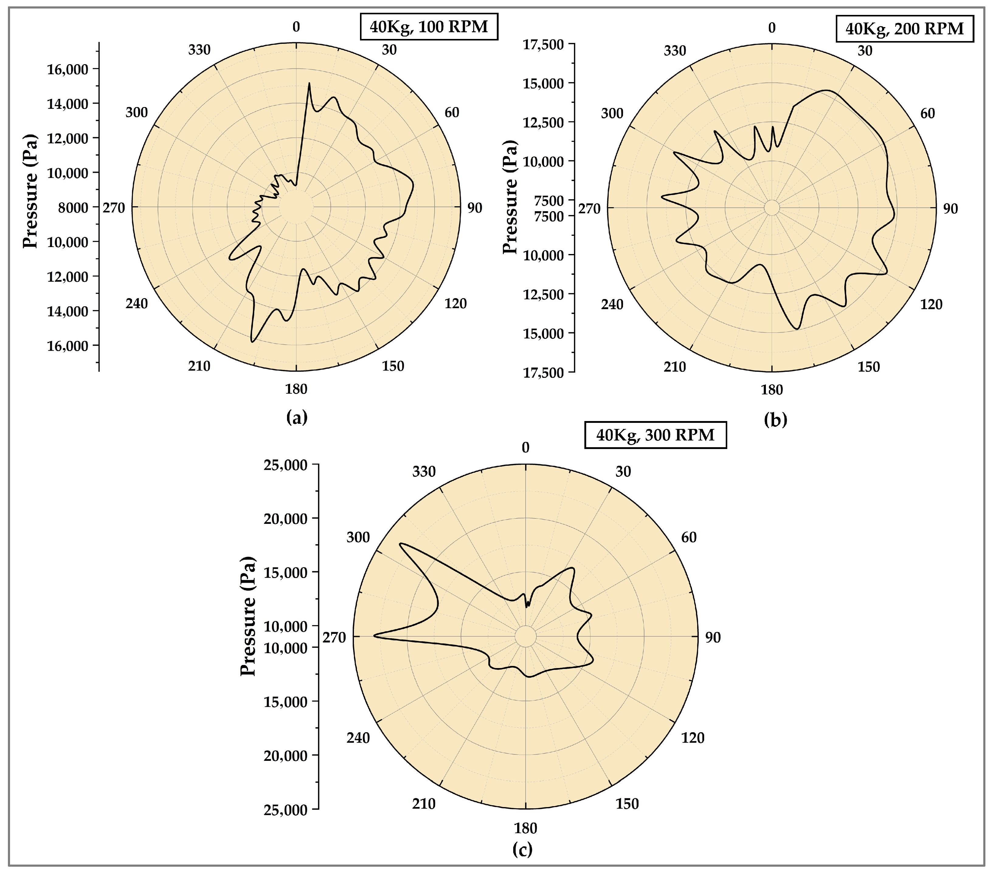
Figure 19 and Figure 20 show the experimentally obtained polar pressure distributions at the bearing mid-plane for 30 kg and 40 kg upward loads. At 100 RPM, both load conditions exhibit pronounced circumferential non-uniformity, with pressure generation confined to narrow angular regions. MGWLBs under 30 kg loads (Figure 19a) exhibit a localized yet comparatively coherent pressure build-up, indicating partial hydrodynamic wedge formation. The sharp pressure fluctuations observed at certain angular locations are likely influenced by measurement noise and localized flow disturbances within the groove–land structure. In contrast, the WLBs under the 40 kg condition (Figure 20a) display more pronounced pressure irregularities and steeper variations. At 200 RPM, both load conditions exhibit a noticeable enlargement in the effective load-carrying pressure region, with diminished measurement noise relative to the lower-speed condition, indicating enhanced hydrodynamic performance. However, the 30 kg load case (Figure 19b) develops a comparatively higher and more spatially coherent pressure field, suggesting more efficient pressure generation and distribution under moderate loading. In contrast, the 40 kg load case (Figure 20b) exhibits reduced pressure uniformity, implying that the higher applied load suppresses circumferential pressure equalization through increased film thinning and intensified groove–land interactions. At 300 RPM, hydrodynamic pressure formation is further strengthened for both load levels, reflecting the dominant influence of speed-induced viscous effects. For the 30 kg load represented in Figure 19c, the pressure field approaches circumferential uniformity, indicative of a stable and well-established hydrodynamic lubrication regime. Conversely, despite the increase in pressure magnitude at 40 kg (Figure 20c), localized pressure concentrations persist, demonstrating that excessive upward loading continues to restrict pressure homogenization by limiting film recovery even at elevated rotational speeds.
Figure 19.
Polar representation of water film pressures in MGWLB for varying speeds under 30 kg upward load. (a) 100 RPM (b) 200 RPM (c) 300 RPM.
Figure 20.
Polar representation of water film pressures in MGWLB for varying speeds under 40 kg upward load. (a) 100 RPM (b) 200 RPM (c) 300 RPM.
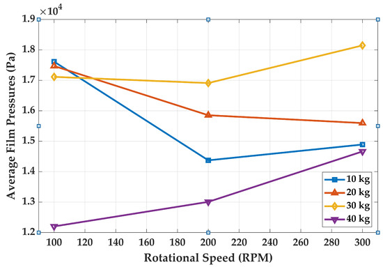
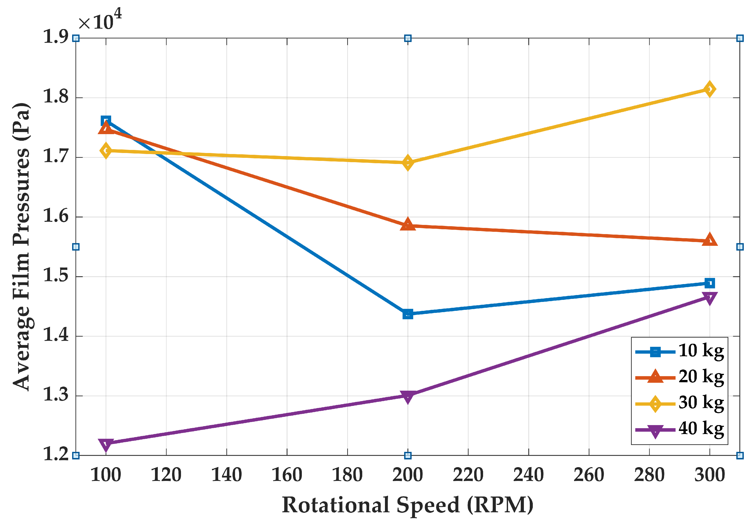
Figure 21 illustrates the variation in average hydrodynamic film pressures developed in the MGWLB with filleted V-shaped grooves as a function of rotational speed for different upward load conditions (10–40 kg). For the 10 kg load, the average film pressure decreases markedly as the speed increases from 100 to 200 RPM, followed by a slight recovery at 300 RPM, resulting in an overall reduction of approximately 11% across the investigated speed range. Such a trend indicates that at relatively low loads, pressure generation is influenced by changes in flow redistribution and hydrodynamic entrainment rather than sustained wedge reinforcement. Under a 20 kg load, the pressure variation with speed becomes less pronounced, where only a marginal reduction of about 1–2% is observed between 100 and 200 RPM, followed by an increase of approximately 7–8% at 300 RPM. Such variation indicates that speed-induced viscous effects contribute progressively more to hydrodynamic pressure generation as the applied load increases. For the 30 kg load, the average film pressure exhibits a gradual increase with rotational speed, showing an overall rise of nearly 20% from 100 to 300 RPM. The observed positive speed dependence signifies intensified hydrodynamic wedge action and increased load-carrying capacity driven by elevated journal surface velocity. At the 40 kg load level, the steady rise in average pressure with speed demonstrates the dominant influence of rotational speed on hydrodynamic pressure formation and film maintenance under heavy loading. The consistent pressure rise at elevated speeds suggests that increased viscous shear and lubricant entrainment effectively compensate for the greater load-induced film thinning.
Figure 21.
Average film pressures of WLB measured from the experimental test setup.
5.2. Influence of Groove Structure on Water Film Pressures: CFD Study
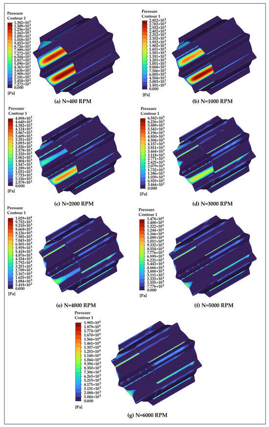
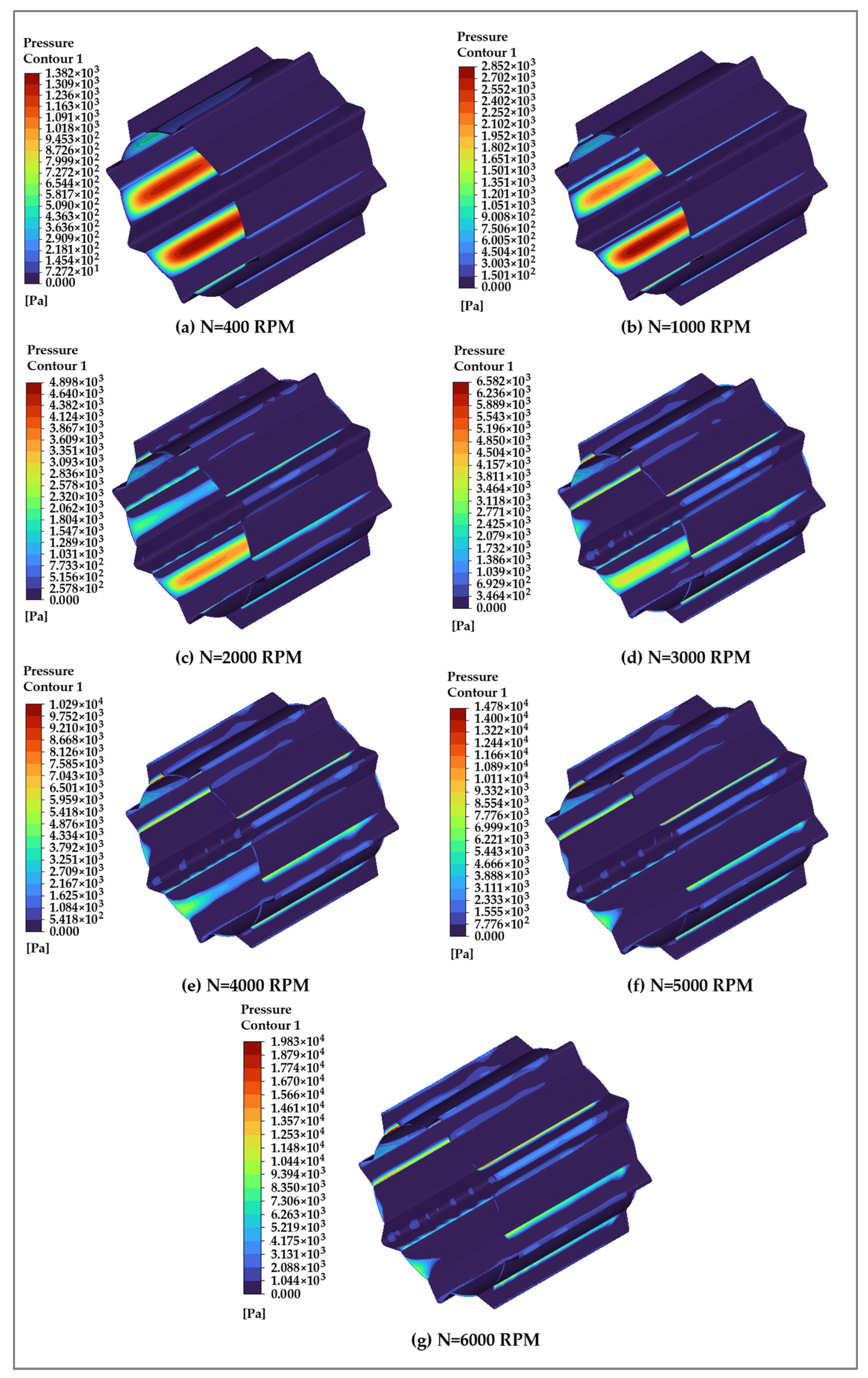
The effect of the journal rotational speed on the hydrodynamic pressure characteristics of the water film in multi-grooved water-lubricated bearings was evaluated using CFD simulations. In the present study, the journal and bearing liner were assumed to be nominally smooth to examine the influence of groove geometry and operating conditions on hydrodynamic pressure development independently. While surface roughness can affect film formation, pressure distribution, and frictional behavior, its influence is expected to be secondary under the predominantly hydrodynamic conditions considered. The interaction between surface roughness and groove-induced flow features may become more significant at lower speeds or higher loads and is identified as an important direction for future investigation. Figure 22 illustrates the evolution of fluid film pressure contours within the multi-grooved water-lubricated bearing with filleted V-shaped grooves as the journal rotational speed increases from 400 to 6000 RPM. At lower speeds (400–1000 RPM), pressure generation is relatively modest and localized primarily within the converging regions of the groove–land interfaces, indicating limited hydrodynamic action due to reduced shear-driven flow. As the rotational speed increased to intermediate levels (2000–3000 RPM), a substantial rise in pressure magnitude was observed, accompanied by an expansion of the high-pressure zones along the load-carrying regions of the bearing. Such behavior reflects enhanced hydrodynamic wedge formation and increased lubricant entrainment into the converging clearance. At higher speeds (4000–6000 RPM), the pressure contours exhibit pronounced intensification and elongation along the groove edges and bearing lands, with peak pressure values increasing significantly. The pressure distribution becomes more uniformly developed circumferentially, indicating stronger fluid momentum transfer and improved load-carrying capability. The filleted V-shaped groove geometry promotes smooth pressure buildup by reducing sharp flow separations at groove edges, thereby enabling efficient pressure generation at elevated speeds.
Figure 22.
Fluid film pressure contours in the fluid domain of multi-grooved WLB with filleted V-shaped groove.
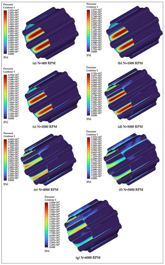
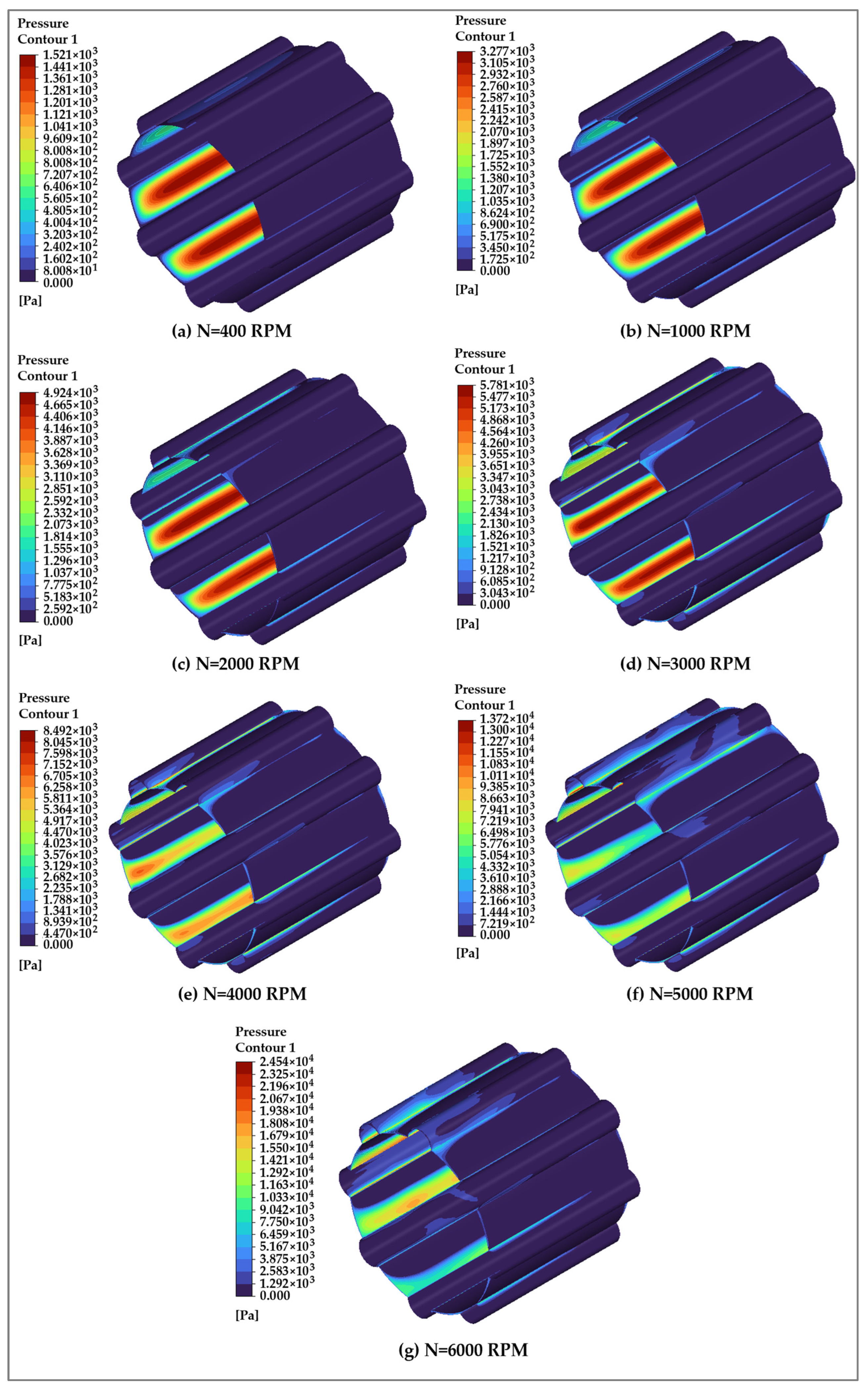
Figure 23 presents the fluid film pressure contours for the multi-grooved water-lubricated bearing with a semicircular groove geometry over a journal speed range of 400–6000 RPM. In comparison with the filleted V-shaped groove configuration shown in Figure 22, the semicircular groove produces a comparatively smoother pressure field with reduced circumferential pressure gradients. The pressure development is primarily governed by gradual lubricant entrainment into the converging clearance, resulting in a more evenly distributed hydrodynamic pressure along the bearing lands. At lower speeds (400–1000 RPM), pressure generation is limited and primarily confined to the converging regions within the bearing lands adjacent to the groove exits. The pressure contours remain localized, indicating relatively weak hydrodynamic action due to reduced lubricant entrainment. As the rotational speed increases to intermediate levels (2000–3000 RPM), a noticeable rise in pressure magnitude is observed, accompanied by a broader spatial distribution of high-pressure zones along the circumferential direction. The semicircular groove profile facilitates smoother lubricant flow into the converging clearance, resulting in more continuous pressure development across the load-carrying regions. At higher speeds (4000–6000 RPM), the pressure contours intensify significantly, with elongated high-pressure bands forming along the bearing lands. This reflects enhanced shear-driven flow and improved hydrodynamic wedge formation, leading to increased load-carrying capability. Compared with the filleted V-shaped groove configuration shown in Figure 22, the semicircular groove model exhibits a more uniformly distributed hydrodynamic pressure field, particularly at intermediate and higher rotational speeds. The rounded groove profile mitigates sharp geometric transitions, thereby reducing abrupt flow acceleration and suppressing localized pressure intensification near groove edges that is characteristic of the filleted V-shaped groove. As a result, the pressure gradients in the semicircular groove configuration are smoother, leading to a more evenly extended load-supporting region along the bearing surface. Overall pressure increases with journal speed, but peak pressures remain lower than those of the filleted V-shaped groove, particularly beyond 3000 RPM. Above 4000 RPM, pressure contours become more circumferentially continuous, indicating improved lubricant stability and fewer localized spikes. This suggests a trade-off between peak pressure and pressure uniformity, with the semicircular groove promoting more distributed support and better operational stability under water-lubricated conditions.
Figure 23.
Fluid film pressure contours in the fluid domain of multi-grooved WLB with semicircular groove.
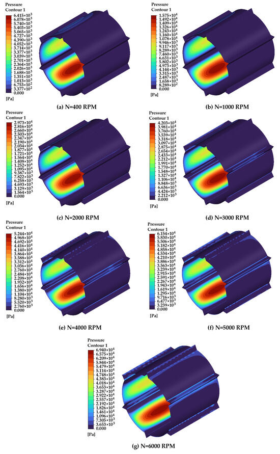
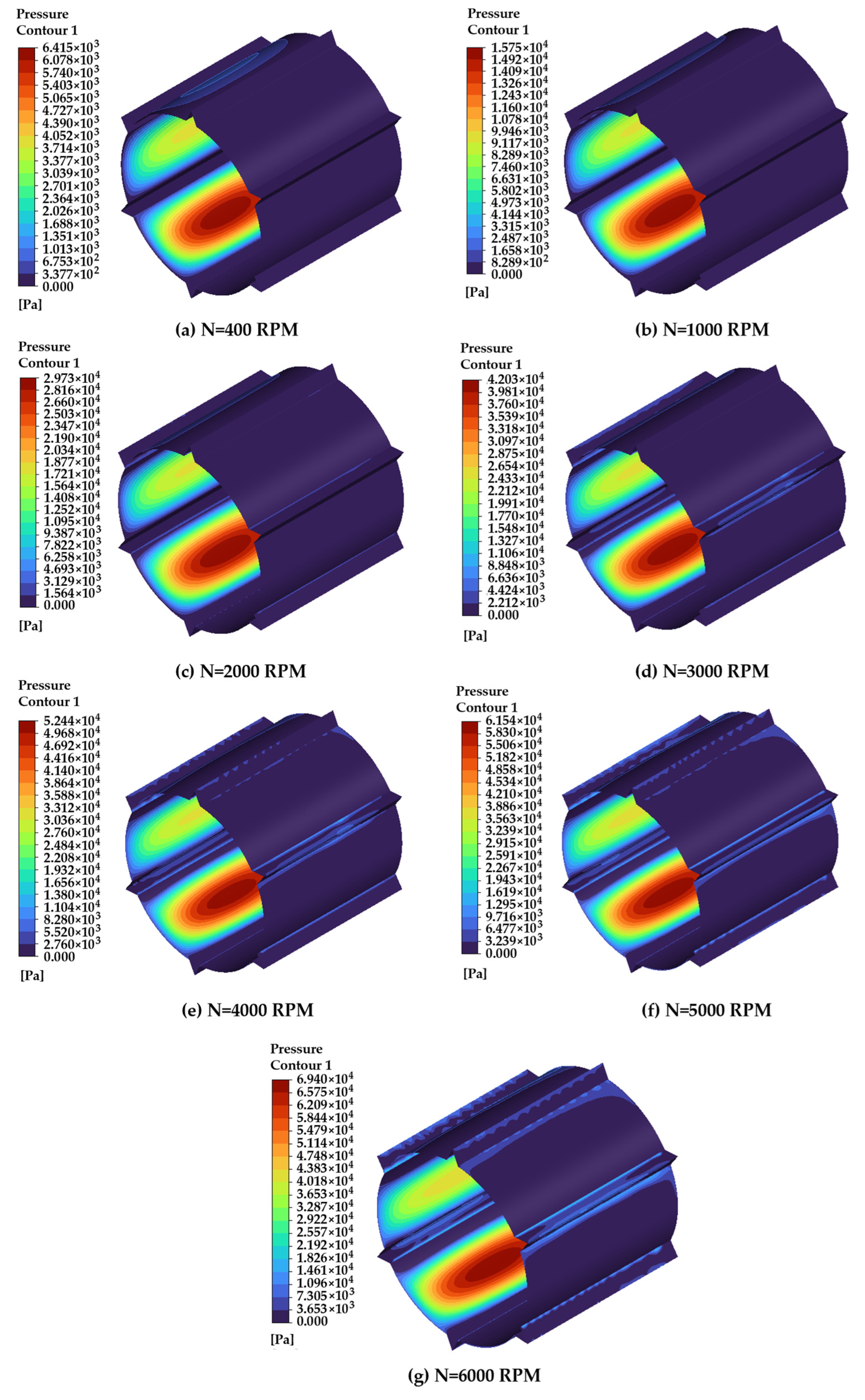
Figure 24 presents the film pressure contours for the multi-grooved WLB with short V-shaped groove geometry over a journal speed range of 400–6000 RPM. Even at lower rotational speeds (400–1000 RPM), the short V-shaped groove configuration generates relatively pronounced pressure zones within the converging clearance, indicating an early onset of hydrodynamic wedge action. As the journal speed increases to intermediate values (2000–3000 RPM), the pressure magnitude rises sharply, and the high-pressure regions become more concentrated and spatially confined near the groove–land junctions. This behavior reflects strong flow acceleration and enhanced squeeze effects induced by the truncated V-shaped profile. At higher rotational speeds (4000–6000 RPM), the pressure contours exhibit substantial intensification, with peak pressure levels significantly exceeding those observed in the other groove configurations. The high-pressure zones remain highly localized, suggesting aggressive pressure build-up driven by abrupt geometric convergence and restricted lubricant redistribution. While this leads to a superior load-carrying capability, it also results in steeper pressure gradients and increased non-uniformity in the pressure field. In comparison with the semicircular groove configuration shown in Figure 23, the short V-shaped groove produces markedly higher peak pressures but exhibits reduced circumferential pressure uniformity. The semicircular groove promotes smoother lubricant entrainment and pressure homogenization, whereas the short V-shaped groove amplifies local hydrodynamic effects through sharper geometric contraction. Relative to the filleted V-shaped groove presented in Figure 22, the short V-shaped groove further intensifies pressure localization due to its truncated geometry, surpassing the filleted design in peak pressure generation while sacrificing pressure smoothness.
Figure 24.
Fluid film pressure contours in the fluid domain of multi-grooved WLB with short V-shaped groove.
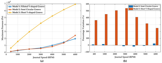
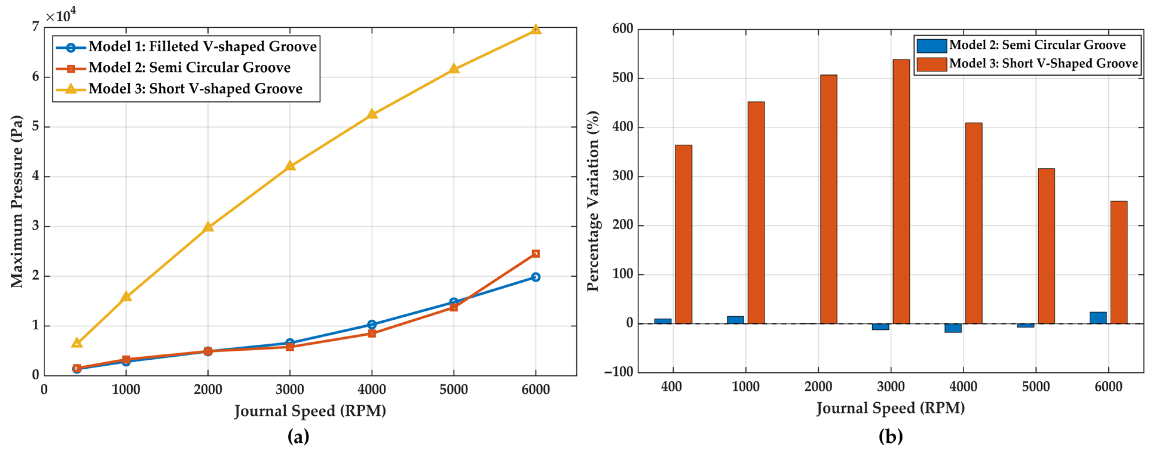
Figure 25a compares the maximum hydrodynamic film pressures developed in the water-lubricated bearings for the three different groove configurations over the investigated journal speed range. For all cases, the maximum pressure increases with rotational speed, reflecting strengthened hydrodynamic action due to enhanced lubricant entrainment and shear. Among the configurations, the short V-shaped groove consistently produces the highest pressure levels, followed by the semicircular groove and the filleted V-shaped groove. The relative differences between the groove geometries are more clearly highlighted through the percentage variation plot shown in Figure 25b, where the filleted V-shaped groove is taken as the reference. The semicircular groove exhibits relatively small percentage deviations, remaining close to the reference across most speeds, which indicates comparable pressure generation capability with slightly smoother pressure development. In contrast, the short V-shaped groove shows a substantial positive percentage variation, particularly at low to intermediate speeds, demonstrating its strong ability to amplify local hydrodynamic pressure. Although the percentage variation for the short V-shaped groove decreases gradually at higher speeds, it remains significantly higher than that of the other configurations throughout the operating range.
Figure 25.
(a) Variation in maximum film pressure with journal speed for different groove geometries, and (b) percentage variation in maximum pressure relative to filleted V-shaped groove.
5.3. Influence of Groove Structure on Flow Field Characteristics: CFD Analysis
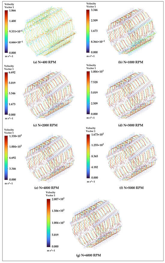
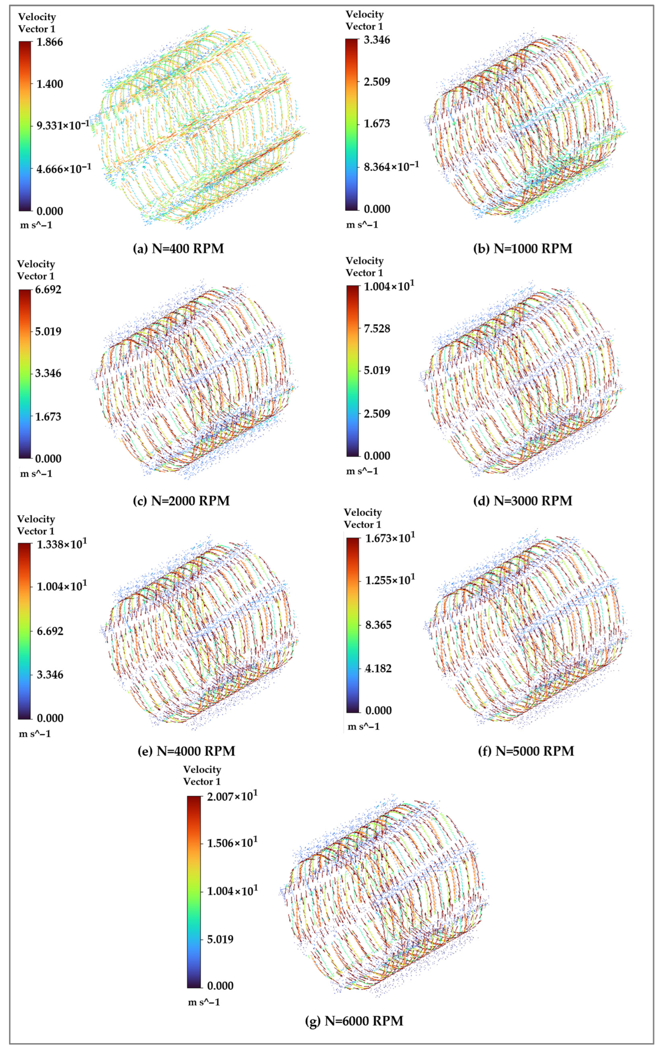
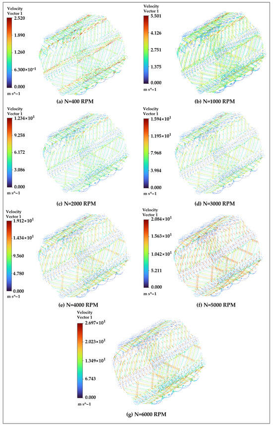
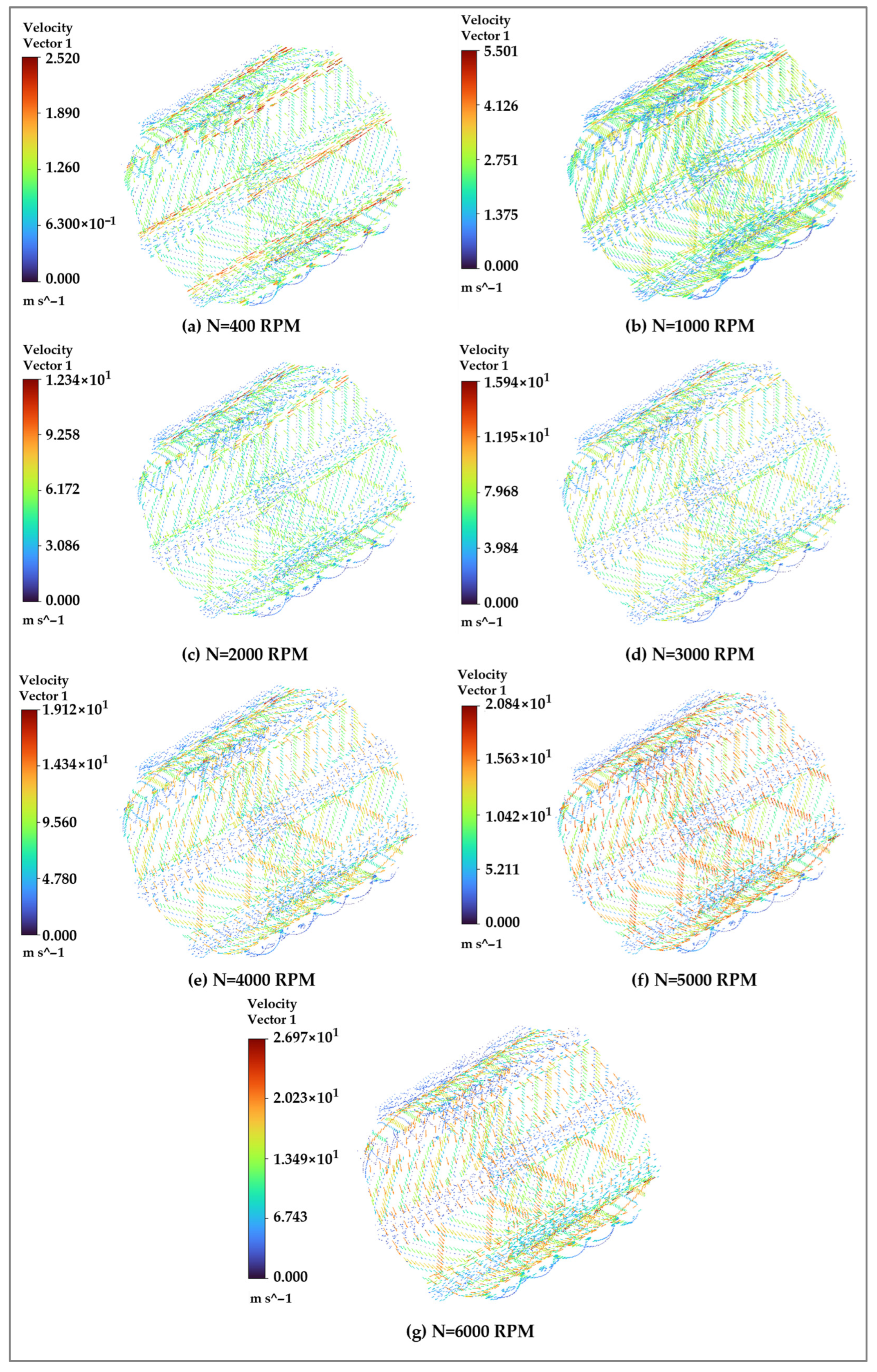
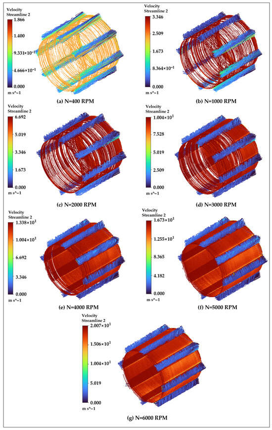
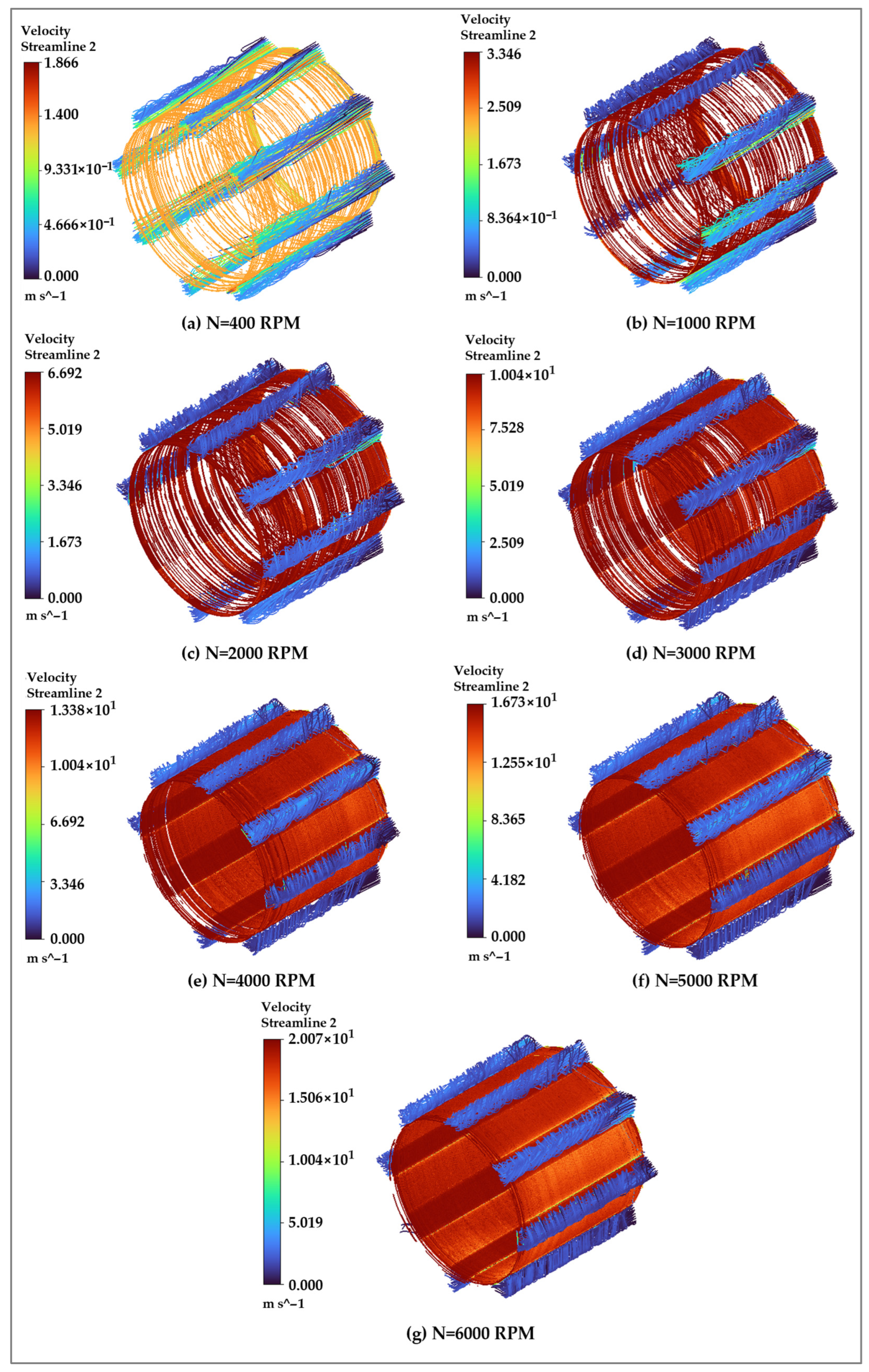
The role of groove structure on the internal flow field characteristics of water-lubricated bearings was examined using CFD simulations. The analysis provides insight into the flow mechanisms responsible for pressure generation, lubricant transport, and overall hydrodynamic performance. Figure 26 presents the velocity vector distributions within the fluid domain of the multi-grooved water-lubricated bearing with a filleted V-shaped groove for journal speeds ranging from 400 to 6000 RPM. At lower rotational speeds (400–1000 RPM), the flow field is characterized by relatively low velocity magnitudes, with smooth and orderly streamlines following the circumferential motion induced by journal rotation. The lubricant motion remains largely attached to the bearing surface, indicating stable shear-driven flow with limited secondary motion. As the rotational speed increases to intermediate values (2000–3000 RPM), the velocity magnitude increases significantly, and pronounced axial and circumferential flow components develop near the groove regions. The filleted V-shaped groove promotes gradual flow redirection, allowing the lubricant to be efficiently guided along the groove–land interfaces without abrupt separation. This results in enhanced lubricant entrainment and improved mixing within the fluid film. At higher speeds (4000–6000 RPM), the flow field becomes more dynamic, with high-velocity streaks forming along the groove edges and bearing lands. The velocity vectors exhibit stronger circumferential alignment accompanied by localized axial transport, indicating intensified shear and momentum transfer from the rotating journal to the lubricant. Despite the increased flow intensity, the rounded grooved ends help maintain flow coherence and limit excessive recirculation, contributing to stable flow development even at elevated speeds.
Figure 26.
Flow field variation developed in the fluid domain of multi-grooved WLB with filleted V-shaped groove.
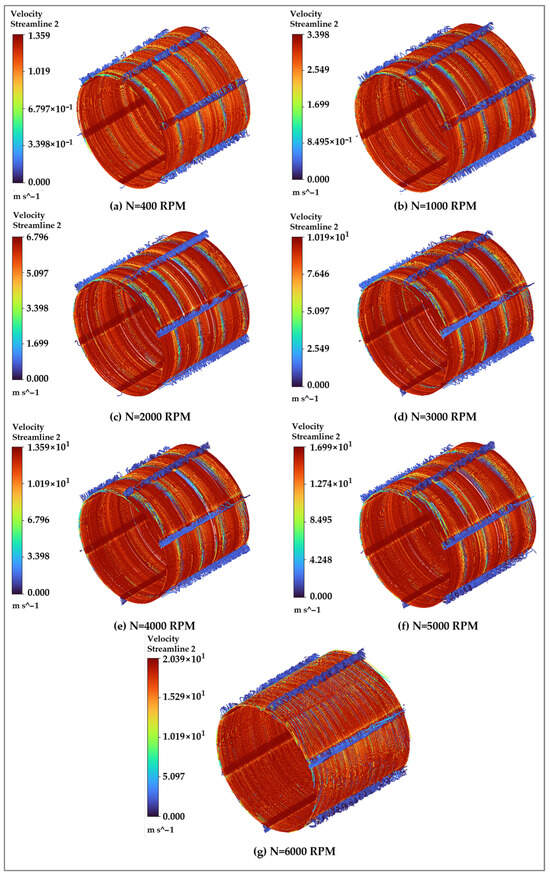
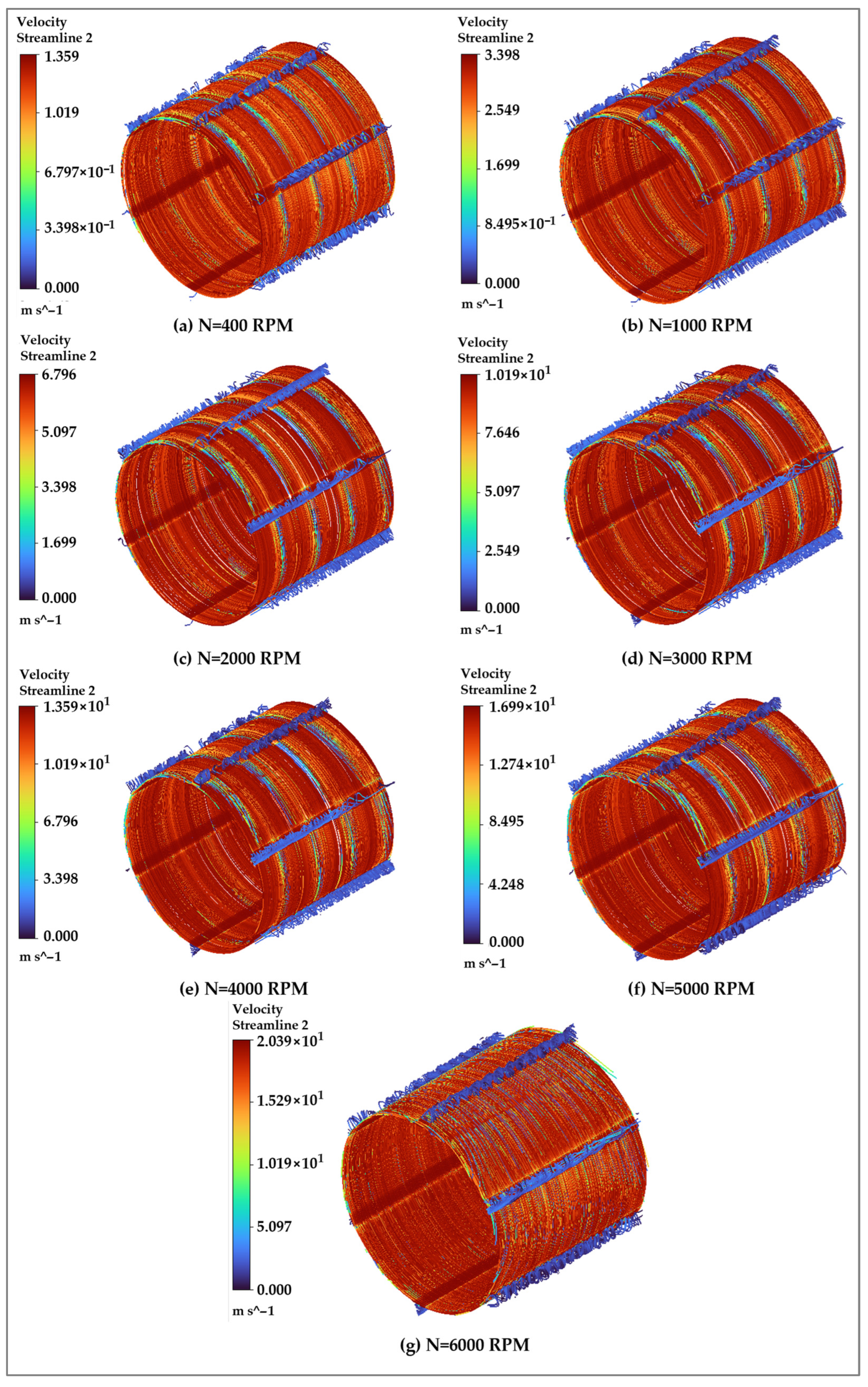
Figure 27 and Figure 28 illustrate the velocity vector distributions within the fluid domain of multi-grooved water-lubricated bearings with semicircular and short V-shaped groove geometries. These figures highlight the influence of groove shape on lubricant flow directionality, velocity magnitude, and flow uniformity under increasing rotational speeds. For the semicircular groove configuration shown in Figure 27, the flow field exhibits smooth and coherent velocity vectors across all operating speeds. At lower speeds, the lubricant motion is predominantly circumferential, closely following the journal rotation with limited secondary flow. As the speed increases, the velocity magnitude rises steadily, and mild axial flow components develop near the groove regions. The rounded groove geometry facilitates gradual flow redirection, resulting in a relatively uniform velocity distribution and limited flow separation even at higher speeds. This indicates stable lubricant transport and effective momentum diffusion throughout the bearing clearance. In contrast, the short V-shaped groove configuration presented in Figure 28 shows a more aggressive flow response. Even at moderate speeds, pronounced velocity gradients and localized high-velocity regions appear near the groove–land interfaces. As the journal speed increases, the flow field becomes increasingly non-uniform, with strong axial and circumferential velocity components concentrated around the truncated groove edges. This behavior reflects intensified shear and flow acceleration caused by the abrupt geometric contraction associated with the short V-shaped groove, leading to enhanced lubricant entrainment but also increased flow complexity. When compared directly, the semicircular groove promotes smoother and more uniformly distributed flow patterns, contributing to stable hydrodynamic conditions and reduced velocity fluctuations. Conversely, the short V-shaped groove enhances local flow acceleration and velocity magnitude, which supports higher pressure generation but at the expense of increased flow non-uniformity and potential local instabilities. These contrasting flow characteristics are consistent with the pressure trends observed earlier and underscore the strong coupling between groove geometry, flow field structure, and hydrodynamic performance in water-lubricated bearings.
Figure 27.
Flow field variation developed in the fluid domain of multi-grooved WLB with semicircular groove.
Figure 28.
Flow field variation developed in the fluid domain of multi-grooved WLB with short V-shaped groove.
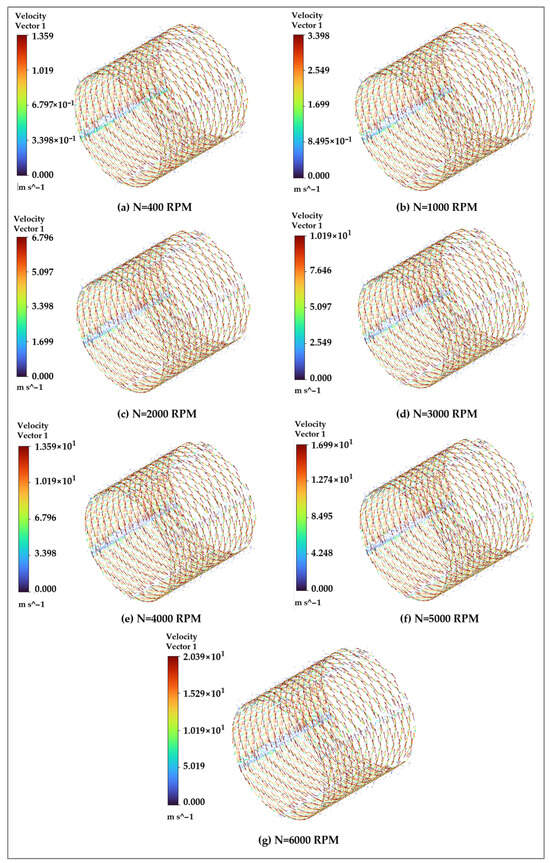
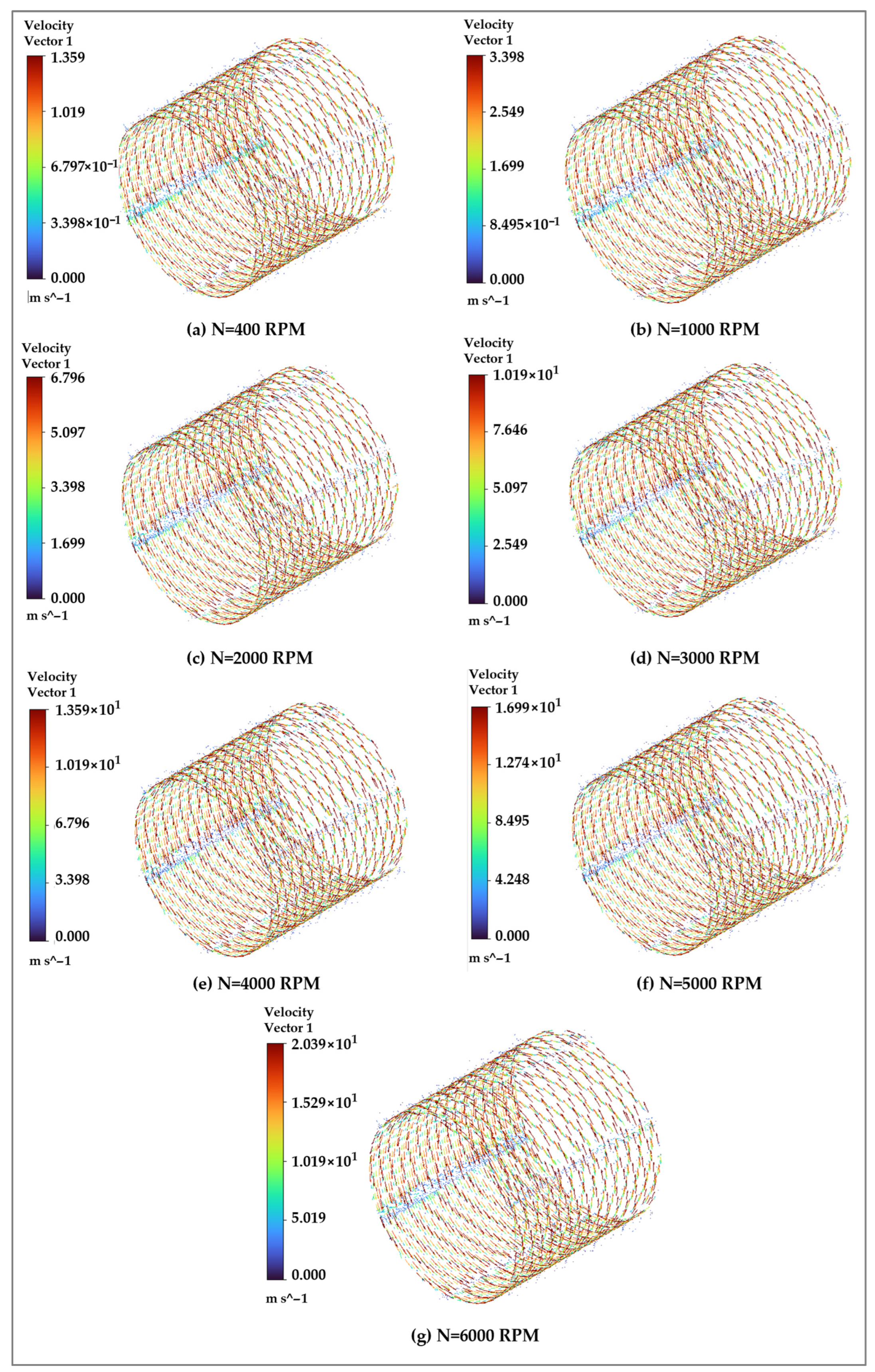
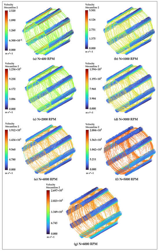
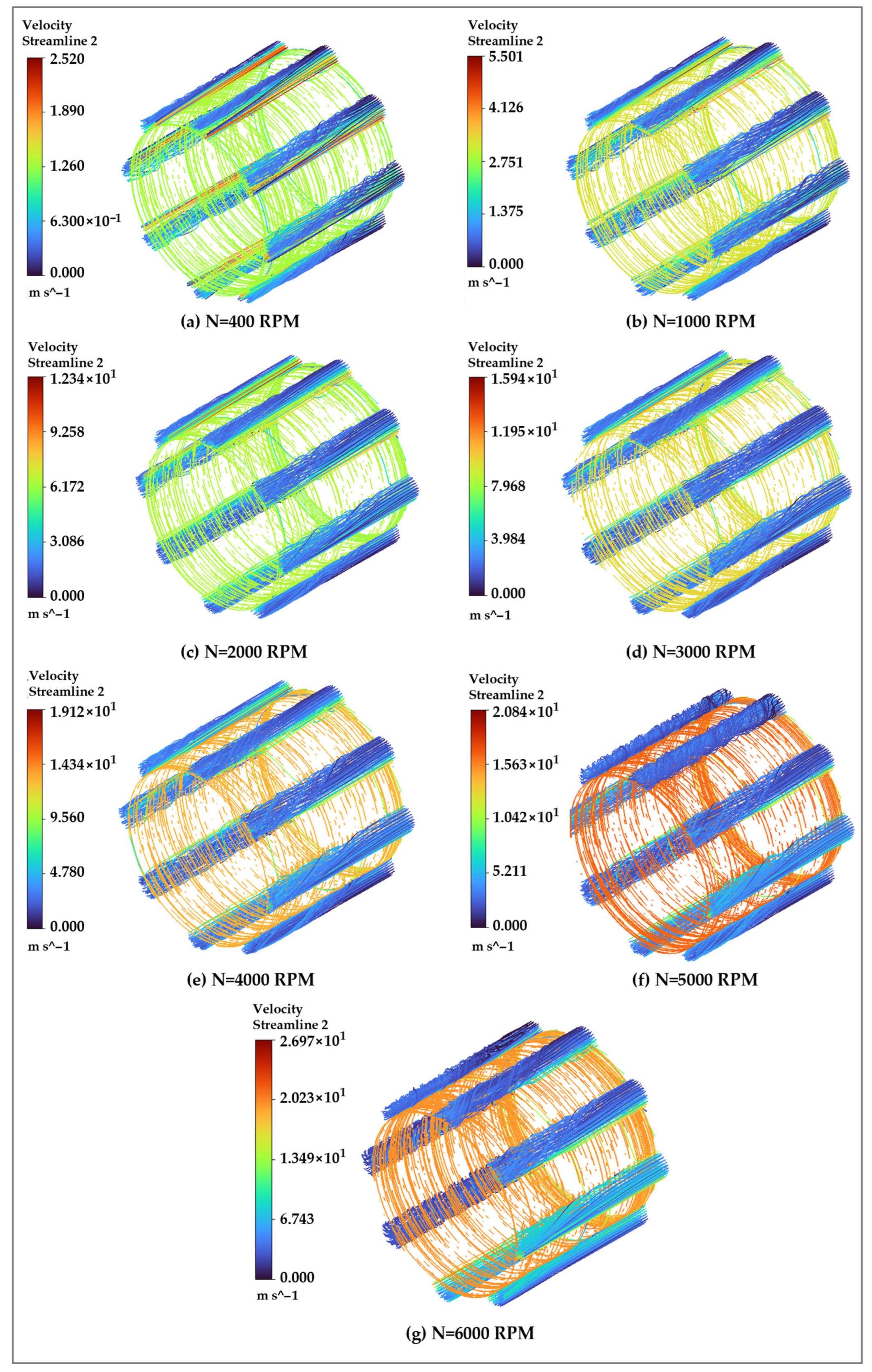
Figure 29, Figure 30 and Figure 31 present the velocity distribution within the fluid domain of multi-grooved water-lubricated bearings with filleted V-shaped, semicircular, and short V-shaped groove geometries over a journal speed range of 400–6000 RPM. In all configurations, an increase in journal speed leads to higher lubricant velocities due to enhanced shear-driven motion and stronger momentum transfer from the rotating journal to the water film. However, the spatial distribution and intensity of the velocity field are strongly influenced by the groove geometry. For the filleted V-shaped groove configuration (Figure 29), the velocity field is characterized by smooth circumferential flow with gradually varying velocity gradients. The rounded groove edges facilitate controlled flow acceleration and minimize abrupt changes in flow direction, resulting in stable lubricant transport and balanced axial and circumferential velocity components. This behavior supports steady hydrodynamic pressure development while limiting excessive shear localization, which is beneficial for reducing frictional losses and maintaining stable operating conditions. The semicircular groove configuration (Figure 30) exhibits the most uniform velocity distribution across the fluid domain. The absence of sharp geometric transitions allows the lubricant to be entrained smoothly into the converging clearance, promoting even momentum diffusion and reducing localized velocity amplification. This uniform flow structure contributes to improved flow stability and reduced velocity fluctuations, which can be advantageous in applications where consistent lubrication, reduced vibration, and enhanced operational reliability are critical.
Figure 29.
Velocity distribution in the fluid domain of multi-grooved WLB with filleted V-shaped groove.
Figure 30.
Velocity distribution in the fluid domain of multi-grooved WLB with semicircular groove.
Figure 31.
Velocity distribution in the fluid domain of multi-grooved WLB with short V-shaped groove.
In contrast, the short V-shaped groove configuration (Figure 31) produces significantly higher local velocity magnitudes, particularly near the groove–land interfaces and converging regions. The truncated V-shaped profile induces strong flow acceleration and intensified shear, leading to localized high-velocity zones within the lubricant film. While this aggressive flow behavior enhances lubricant entrainment and supports higher hydrodynamic pressure generation, it also introduces pronounced velocity gradients that may increase frictional heating and localized stresses within the fluid film. From a practical perspective, these observations highlight a clear trade-off in groove design. The semicircular groove is well suited for applications prioritizing flow uniformity, operational stability, and reduced wear risk, whereas the short V-shaped groove is more effective for maximizing load-carrying capacity under high-speed conditions. The filleted V-shaped groove offers an intermediate response, balancing enhanced hydrodynamic action with controlled flow behavior. These insights provide valuable guidance for selecting groove geometries tailored to specific performance requirements in water-lubricated bearing applications.
6. Conclusions
This study presented a detailed experimental and numerical investigation of hydrodynamic pressure development and flow behavior in multi-grooved water-lubricated bearings (MGWLBs) under operating conditions representative of marine stern tube applications. A renovated experimental test rig enabled repeatable measurement of circumferential water film pressures at the bearing mid-plane for rotational speeds between 100 and 300 RPM and applied upward loads ranging from 10 to 40 kg. The experimental results demonstrated that at low speeds (100 RPM), pressure generation was highly localized and circumferentially non-uniform for all load levels, indicating limited lubricant entrainment. With increasing speed, the pressure field expanded circumferentially and became smoother, signifying improved film continuity and stable hydrodynamic lubrication. For the 10 kg load case, the average film pressure showed an overall reduction of approximately 11% between 100 and 300 RPM, whereas for the 20 kg load, a net increase of about 7–8% was observed at 300 RPM. At higher loads of 30 kg and 40 kg, the average film pressure increased steadily with speed, with the 30 kg load exhibiting an overall rise of nearly 20% from 100 to 300 RPM, highlighting the dominant role of speed-induced viscous effects under moderate to heavy loading.
CFD simulations conducted over a wider speed range of 400–6000 RPM further revealed the strong influence of groove geometry on pressure magnitude, spatial distribution, and flow structure. Filleted V-shaped grooves produced smooth pressure development with moderate gradients and stable flow behavior. Semicircular grooves resulted in more uniform pressure and velocity distributions, with reduced localized intensification, but exhibited lower peak pressures compared with other geometries. In contrast, short V-shaped grooves consistently generated the highest peak pressures across the investigated speed range, with percentage increases in maximum pressure significantly exceeding those of the filleted V-shaped reference geometry, particularly at low to intermediate speeds. However, this enhanced pressure generation was accompanied by increased pressure localization and flow non-uniformity. Hence, the combined experimental and numerical results quantify key trade-offs between pressure magnitude, circumferential uniformity, and flow stability, providing design-oriented guidance for selecting groove geometry and operating conditions in marine water-lubricated bearings. Future work will extend the present study to include long-term endurance testing, tribological evaluation, and dynamic performance characterization to assess durability and rotor–bearing system interactions under sustained operating conditions.
Author Contributions
Conceptualization, G.H., N.K. and R.M.; methodology, K.N.R., G.H., N.K. and R.M.; validation, K.N.R., G.H. and N.K.; formal analysis, K.N.R. and G.H.; investigation, K.N.R., G.H. and R.M.; data curation, V. and S.K.B.; writing—original draft preparation, K.N.R. and G.H.; writing—review and editing, G.M.C. and V.; visualization, N.K., G.M.C., S.K.B. and V.; supervision, C.P.S. and G.M.C.; project administration, N.K., S.K.B. and C.P.S. All authors have read and agreed to the published version of the manuscript.
Funding
This research received no external funding.
Data Availability Statement
The raw data supporting the conclusions of this article will be made available by the authors on request.
Acknowledgments
The authors would like to thank Manipal Institute of Technology, MAHE Manipal for their valuable infrastructure support and cooperation during this study. Portions of this manuscript were prepared with the assistance of ChatGPT (GPT-5, OpenAI), which was used to improve the clarity, grammar, and readability of the text. The content and scientific interpretations were fully conceived, reviewed, and approved by the authors.
Conflicts of Interest
The authors declare no conflicts of interest.
References
- Xie, Z.; Jiao, J.; Yang, K.; Zhang, H. A state-of-art review on the water-lubricated bearing. Tribol. Int. 2023, 180, 108276. [Google Scholar] [CrossRef] [Scilit]
- Orndorff, R.L. Water-Lubricated Rubber Bearings, History and New Developments. Nav. Eng. J. 1985, 97, 39–52. [Google Scholar] [CrossRef] [Scilit]
- Zhou, G.; Wang, J.; Han, Y.; Wei, B.; Tang, B.; Zhong, P. An Experimental Study on Film Pressure Circumferential Distribution of Water-Lubricated Rubber Bearings with Multiple Grooves. Tribol. Trans. 2017, 60, 385–391. [Google Scholar] [CrossRef] [Scilit]
- Orndorff, R.; Foster, L.; Sheppert, R. From Lab to Field: New High Performance Water Lubricated Bearings. In Proceedings of the World Tribology Congress III, Washington, DC, USA, 12–16 September 2005; ASMEDC: Washington, DC, USA, 2005; Volume 2, pp. 55–56. [Google Scholar] [CrossRef] [Scilit]
- Wang, N.; Meng, Q.; Wang, P.; Geng, T.; Yuan, X. Experimental Research on Film Pressure Distribution of Water-Lubricated Rubber Bearing With Multiaxial Grooves. J. Fluids Eng. 2013, 135, 084501. [Google Scholar] [CrossRef] [Scilit]
- Ginzburg, B.M.; Tochil’nikov, D.G.; Bakhareva, V.E.; Anisimov, A.V.; Kireenko, O.F. Polymeric materials for water-lubricated plain bearings. Russ. J. Appl. Chem. 2006, 79, 695–706. [Google Scholar] [CrossRef] [Scilit]
- Jahanmir, S.; Ozmen, Y.; Ives, L.K. Water Lubrication of Silicon Nitride in Sliding. Tribol. Lett. 2004, 17, 409–417. [Google Scholar] [CrossRef] [Scilit]
- Jia, J.; Chen, J.; Zhou, H.; Wang, J.; Zhou, H. Friction and wear properties of bronze–graphite composite under water lubrication. Tribol. Int. 2004, 37, 423–429. [Google Scholar] [CrossRef] [Scilit]
- Litwin, W.; Olszewski, A. Water-Lubricated Sintered Bronze Journal Bearings—Theoretical and Experimental Research. Tribol. Trans. 2014, 57, 114–122. [Google Scholar] [CrossRef] [Scilit]
- Li, X.; Guo, Z.; Huang, Q.; Yuan, C. Application of Bionic Tribology in Water-Lubricated Bearing: A Review. J. Bionic Eng. 2022, 19, 902–934. [Google Scholar] [CrossRef] [Scilit]
- Litwin, W. Experimental research on water lubricated three layer sliding bearing with lubrication grooves in the upper part of the bush and its comparison with a rubber bearing. Tribol. Int. 2015, 82, 153–161. [Google Scholar] [CrossRef] [Scilit]
- Litwin, W. Marine Propeller Shaft Bearings under Low-Speed Conditions: Water vs. Oil Lubrication. Tribol. Trans. 2019, 62, 839–849. [Google Scholar] [CrossRef] [Scilit]
- Litwin, W. Properties comparison of rubber and three layer PTFE-NBR-bronze water lubricated bearings with lubricating grooves along entire bush circumference based on experimental tests. Tribol. Int. 2015, 90, 404–411. [Google Scholar] [CrossRef] [Scilit]
- Wodtke, M.; Litwin, W. Water-lubricated stern tube bearing-experimental and theoretical investigations of thermal effects. Tribol. Int. 2021, 153, 106608. [Google Scholar] [CrossRef] [Scilit]
- Litwin, W. Influence of local bush wear on water lubricated sliding bearing load carrying capacity. Tribol. Int. 2016, 103, 352–358. [Google Scholar] [CrossRef] [Scilit]
- Litwin, W.; Dymarski, C. Experimental research on water-lubricated marine stern tube bearings in conditions of improper lubrication and cooling causing rapid bush wear. Tribol. Int. 2016, 95, 449–455. [Google Scholar] [CrossRef] [Scilit]
- Ye, X.; Wang, J.; Zhang, D.; Hu, L.; She, X. Experimental Research of Journal Orbit for Water-Lubricated Bearing. Math. Probl. Eng. 2016, 2016, 1–11. [Google Scholar] [CrossRef] [Scilit]
- Avishai, D.; Morel, G. Experimental Investigation of Lubrication Regimes of a Water-Lubricated Bearing in the Propulsion Train of a Marine Vessel. J. Tribol. 2020, 143, 041803. [Google Scholar] [CrossRef] [Scilit]
- Han, Y.; Yin, L.; Xiang, G.; Zhou, G.; Chen, H.; Zheng, X. An experimental study on the tribological performance of water-lubricated journal bearings with three different materials. Ind. Lubr. Tribol. 2020, 72, 1159–1165. [Google Scholar] [CrossRef] [Scilit]
- Litwin, W.; Wasilczuk, M.; Wodtke, M.; Olszewski, A. The influence of polymer bearing material and lubricating grooves layout on wear of journal bearings lubricated with contaminated water. Tribol. Int. 2023, 179, 108159. [Google Scholar] [CrossRef] [Scilit]
- Xie, Z.; Zhang, Y.; Zhou, J.; Zhu, W. Theoretical and experimental research on the micro interface lubrication regime of water lubricated bearing. Mech. Syst. Signal Process. 2021, 151, 107422. [Google Scholar] [CrossRef] [Scilit]
- Xie, Z.; Jiao, J.; Yang, K. Theoretical and experimental study on the fluid-structure-acoustic coupling dynamics of a new water lubricated bearing. Tribol. Int. 2023, 177, 107982. [Google Scholar] [CrossRef] [Scilit]
- Xie, Z.; Liu, H. Experimental research on the interface lubrication regimes transition of water lubricated bearing. Mech. Syst. Signal Process. 2020, 136, 106522. [Google Scholar] [CrossRef] [Scilit]
- Xie, Z.; Shen, N.; Zhu, W.; Tian, W.; Hao, L. Theoretical and experimental investigation on the influences of misalignment on the lubrication performances and lubrication regimes transition of water lubricated bearing. Mech. Syst. Signal Process. 2021, 149, 107211. [Google Scholar] [CrossRef] [Scilit]
- Xie, Z.; Rao, Z.; Liu, H. Effect of Surface Topography and Structural Parameters on the Lubrication Performance of a Water-Lubricated Bearing: Theoretical and Experimental Study. Coatings 2019, 9, 23. [Google Scholar] [CrossRef] [Scilit]
- Tang, D.; Xiang, G.; Guo, J.; Cai, J.; Yang, T.; Wang, J.; Han, Y. On the optimal design of staved water-lubricated bearings driven by tribo-dynamic mechanism. Phys. Fluids 2023, 35, 093611. [Google Scholar] [CrossRef] [Scilit]
- Liu, G.; Li, M. Experimental study on the lubrication characteristics of water-lubricated rubber bearings at high rotating speeds. Tribol. Int. 2021, 157, 106868. [Google Scholar] [CrossRef] [Scilit]
- Chen, S.; Xiang, G.; Fillon, M.; Guo, J.; Wang, J.; Cai, J. On the tribo-dynamic behaviors during start-up of water lubricated bearing considering imperfect journal. Tribol. Int. 2022, 174, 107685. [Google Scholar] [CrossRef] [Scilit]
- Liu, Q.; Ouyang, W.; Li, R.; Jin, Y.; He, T. Experimental research on lubrication and vibration characteristics of water-lubricated stern bearing for underwater vehicles under extreme working conditions. Wear 2023, 523, 204778. [Google Scholar] [CrossRef] [Scilit]
- Ren, T.; Feng, M. Theoretical and experimental study on the stability of water lubricated high speed journal bearing with lobe pockets. Tribol. Int. 2023, 187, 108665. [Google Scholar] [CrossRef] [Scilit]
- Ouyang, W.; Liu, Q.; Xiao, J.; Huang, J.; Zhang, Z.; Wang, L. Experimental study on the distributed lubrication characteristics of full-size water-lubricated stern bearings under hull deformation. Ocean Eng. 2023, 267, 113226. [Google Scholar] [CrossRef] [Scilit]
- Chang, X.; Liu, J.; Yan, X.; Sun, F.; Zhu, H.; Wang, C. Experimental Study on the Effects of Controllable Parameters on the Healthy Operation of SF-2A Material Water-Lubricated Stern Bearing in Multi-Point Ultra-Long Shaft Systems of Ships. J. Mar. Sci. Eng. 2024, 13, 14. [Google Scholar] [CrossRef] [Scilit]
- Liang, P.; Li, X.; Guo, F.; Cao, Y.; Zhang, X.; Jiang, F. Influence of sea wave shock on transient start-up performance of water-lubricated bearing. Tribol. Int. 2022, 167, 107332. [Google Scholar] [CrossRef] [Scilit]
- Wu, C.; Chen, F.; Long, X. The self-excited vibration induced by friction of the shaft-hull coupled system with the water-lubricated rubber bearing and its stick-slip phenomenon. Ocean Eng. 2020, 198, 107002. [Google Scholar] [CrossRef] [Scilit]
- Gengyuan, G.; Zhongwei, Y.; Dan, J.; Xiuli, Z. CFD analysis of load-carrying capacity of hydrodynamic lubrication on a water-lubricated journal bearing. Ind. Lubr. Tribol. 2015, 67, 30–37. [Google Scholar] [CrossRef] [Scilit]
- Zhang, X.; Yin, Z.; Jiang, D.; Gao, G. The design of hydrodynamic water-lubricated step thrust bearings using CFD method. Mech. Ind. 2014, 15, 197–206. [Google Scholar] [CrossRef] [Scilit]
- Wang, Y.; Yin, Z.; Jiang, D.; Gao, G.; Zhang, X. Study of the lubrication performance of water-lubricated journal bearings with CFD and FSI method. Ind. Lubr. Tribol. 2016, 68, 341–348. [Google Scholar] [CrossRef] [Scilit]
- Tauviqirrahman, M.; Jamari, J.; Bagir, M.; Caesarendra, W.; Paryanto, P. Elastohydrodynamic behavior analysis on water-lubricated journal bearing: A study of acoustic and tribological performance based on CFD-FSI approach. J. Braz. Soc. Mech. Sci. Eng. 2022, 44, 1. [Google Scholar] [CrossRef] [Scilit]
- Ambekar, R.; Kumar, N.; Kumar, S.; Girish, H. CFD analysis of cavitated flow in multi-groove water lubricated bearings with partial and full slip effects. Results Eng. 2025, 27, 106693. [Google Scholar] [CrossRef] [Scilit]
- Hariharan, G.A.G.; Kumar, S.; Kumar, N. Enhancing performance in water lubricated bearings with groove structures: A CFD analysis. Cogent Eng. 2024, 11, 2399762. [Google Scholar] [CrossRef] [Scilit]
- Lv, F.; Jiao, C.; Xu, J. Theoretical and experimental investigation on effective length-to-diameter ratio of misaligned water-lubricated bearings. Tribol. Int. 2023, 187, 108712. [Google Scholar] [CrossRef] [Scilit]
- Zhang, X.; Yin, Z.; Jiang, D.; Gao, G.; Wang, Y.; Wang, X. Load carrying capacity of misaligned hydrodynamic water-lubricated plain journal bearings with rigid bush materials. Tribol. Int. 2016, 99, 1–13. [Google Scholar] [CrossRef] [Scilit]
- Xie, Z.; Song, P.; Hao, L.; Shen, N.; Zhu, W.; Liu, H.; Shi, J.; Wang, Y.; Tian, W. Investigation on effects of Fluid-Structure-Interaction (FSI) on the lubrication performances of water lubricated bearing in primary circuit loop system of nuclear power plant. Ann. Nucl. Energy 2020, 141, 107355. [Google Scholar] [CrossRef] [Scilit]
Disclaimer/Publisher’s Note: The statements, opinions and data contained in all publications are solely those of the individual author(s) and contributor(s) and not of MDPI and/or the editor(s). MDPI and/or the editor(s) disclaim responsibility for any injury to people or property resulting from any ideas, methods, instructions or products referred to in the content. |
© 2026 by the authors. Licensee MDPI, Basel, Switzerland. This article is an open access article distributed under the terms and conditions of the Creative Commons Attribution (CC BY) license.