


Abstract
We theoretically examined the optical spectra of a structurally chiral nanocomposite medium with local point-group symmetry, featuring a central twist defect and embedding randomly dispersed metallic nanospheres. We analyzed the optical response under normal and oblique incidence of circularly polarized light, considering various medium parameters such as the nanoparticle filling fraction, structural pitch, and twist defect angle. The transmission and reflection spectra exhibit splitting and widening of the photonic bands driven by the coupling among the defect mode, the Bragg band of the chiral structure, and the omnidirectional bandgaps generated by the metallic inclusions. The spectra are highly sensitive to the nanoparticle volume fraction, offering a mechanism to tune the spectral features of the medium.
1. Introduction
Photonic crystals (PCs) are artificial periodic structures whose ability to mold and control the flow of light has stimulated extensive theoretical and experimental research over the past decades. A particularly interesting type of one-dimensional PCs is constituted by structurally chiral media (SCMs), including cholesteric liquid crystals, cholesteric elastomers, and chiral sculptured thin films [1,2,3]. These continuously nonhomogeneous materials exhibit a helicoidal modulation of anisotropy along a fixed axis and display the circular Bragg phenomenon (CBP), whereby a circularly polarized wave of matching handedness is strongly reflected within a specific wavelength range, while the opposite handedness is transmitted [4]. The intrinsic polarization selectivity and spectral filtering properties of SCMs make them attractive for photonic devices requiring compactness and dynamic tunability.
The appearance of a spectral hole in the reflection spectrum of chiral sculptured thin films has been theoretically and experimentally demonstrated by inserting an anisotropic and homogeneous layer between two slabs of the same chiral sculptured film, or by introducing a twist defect into the chiral sample [5,6]. A twist defect is obtained by rotating one section of the SCM by a specific angle relative to the other section around their common helical axis.
Active control of defect modes and Bragg bands can be achieved by exploiting the strong susceptibility of SCMs to external stimuli such as electric and magnetic fields, temperature, pressure, and mechanical strain. Cholesteric liquid crystals and their polymer-stabilized counterparts provide additional high-Q resonances and multistable operation regimes [7,8]. Cholesteric liquid crystal elastomers further combine mechanical compliance with optical chirality, allowing reversible strain-induced tuning of single and multiplet defect modes [9,10,11,12].
An alternative strategy for manipulating the spectral response of chiral photonic crystals relies on incorporating resonant nanocomposites with metallic inclusions [13,14,15,16]. The giant plasmonic dispersion introduced by nanoparticles can significantly distort the photonic bandgap (PBG) and the CBP, offering an additional degree of freedom for spectral control. In particular, under oblique incidence of circularly polarized waves, Ref. [16] reported the appearance of three narrow omnidirectional bands –two bandgaps and a pass band– that can be adjusted by varying the filling fraction of metallic nanoparticles dispersed in an SCM. These advances have recently enabled the extension of SCM-based photonic structures toward sensing and biosensing applications, where changes in the dielectric environment associated with chemical or biological analytes are transduced into measurable optical shifts. Notably, optical biosensors based on chiral photonic media provide compact platforms with real-time response, wide dynamic range, and high sensitivity for biomedical diagnostics [17,18,19].
Recent advances in structurally chiral media (SCMs) have enabled enhanced control of polarization-dependent optical responses, including polarization-universal photonic bandgaps in chiral sculptured thin films [20] and tailored chiroptical properties in twisted anisotropic structures [21]. Structural defects, particularly twist and phase discontinuities, provide additional spectral control by introducing localized optical modes within the circular Bragg regime. Their influence on geometric phase and polarization-dependent optical properties has been investigated [22], while the spectral characteristics and quality factors of defect modes in cholesteric resonators have been systematically analyzed [23].
Parallel developments in metallic and hybrid chiral nanomaterials have demonstrated the potential of resonant dispersion and absorption for tailoring optical responses. Integrating metallic nanostructures with chiral environments can enhance light–matter interactions and polarization-dependent optical effects [24,25], while plasmonic superlattices assembled from achiral nanoparticles exhibit pronounced chiroptical responses arising from structural organization [26]. The incorporation of metallic nanospheres into cholesteric elastomers, with and without structural defects, has revealed the dependence of photonic bandgaps, reflection characteristics, and polarization-dependent resonant spectral features on nanoparticle concentration, mechanical deformation, and structural configuration [27,28]. Related investigations have examined the influence of metallic inclusions on the optical response of nanocomposite chiral structures [29], including the Goos–Hänchen shifts of defect modes in structurally chiral media with twist defects [30].
These developments motivate a systematic examination of how the spectral interplay among circular Bragg reflection, defect-induced localized modes, and metallic nanoparticle resonances governs the formation and evolution of multiple transmission and reflection bands. Accordingly, the present theoretical study investigates the polarization-dependent optical spectra of a structurally chiral nanocomposite with a central twist defect and randomly dispersed metallic nanospheres, considering variations in nanoparticle filling fraction, structural pitch, twist-defect angle, and incidence angle. Particular emphasis is placed on reflection-band splitting, spectral broadening, and attenuation of defect-associated transmission features arising from the overlap between the circular Bragg regime and nanoparticle-induced absorption resonances. The results provide physical insight into multiband spectral formation and establish a theoretical basis for designing wavelength-selective, polarization-dependent optical filters through the combined control of structural chirality, defect geometry, and metallic inclusions. In this context, the investigation of defect modes and band-gap engineering in nanocomposite structurally chiral photonic crystals constitutes a promising route toward tunable and multifunctional photonic devices. By combining the polarization selectivity of helicoidal structures resonant media, these systems offer new opportunities for sensing, filtering, and light–matter interaction at the nanoscale.
Here, we analyze the optical properties of a twist defect located at the center of a nanocomposite structurally chiral medium (NSCM) composed of an SCM with local point-group symmetry, containing randomly dispersed silver nanoinclusions. This work investigates an artificial structure that exploits the coupling among the periodic properties of the SCM, the resonant characteristics of the metallic nanoballs and the defect mode, thereby allowing the spectral properties of the NSCM to be tuned by varying the filling fraction of the metallic particles. According to our findings, these media may have potential applications in the detection of metallic particles in fluids. Indeed, chiral sculptured thin films with a twist defect have been proposed as fluid sensors because of their porosity, which enables the infiltration of fluids into these media, thereby altering their optical spectra [31,32].
2. Model and Basic Equations
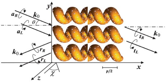
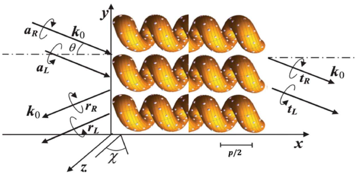
We focus on the study of an obliquely incident electromagnetic plane wave propagating parallel to the plane throughout a nonmagnetic periodic structure surrounded by air and located between the planes and , in which metallic nanoparticles are randomly dispersed. The periodicity axis is parallel to the x-axis and a twist defect is inserted at the middle part of the structure. Within the system, Maxwell’s equations are formulated as a first-order matrix differential equation system for the transverse field components [15]. The impinging wavevector of light forms an angle with the x-axis. The wavenumber is related to the wavelength through the expression .
We modeled the nanocomposite medium as a nondissipative dielectric SCM with spatial period p, locally uniaxial symmetry ( point group), and a small volume fraction f of isotropic metallic inclusions (see Figure 1). The dielectric properties of the system are represented by an effective dielectric tensor which is obtained from a generalized Maxwell-Garnett formalism for anisotropic hosts [16], in which the metallic nanoparticles obey a Drude permittivity , where is the frequency of the propagating wave, c denotes the speed of light in vacuum, represents the background dielectric constant, is the plasma frequency, and is the plasma relaxation rate. For the uniaxial medium, the principal permittivities and define a diagonal tensor in the local coordinate system, whose distinguished axis is tilted by an angle with respect to the laboratory z-axis (see Figure 1). Under these considerations, the effective permittivities and , which depend on frequency and volume fraction, are expressed as follows [15]
Figure 1.
A NSCM with a twist defect at the center of the slab. An electromagnetic wave with wavevector impinges on the structure at an angle with respect to the x-axis. Here, the x-axis is the nonhomogeneity and periodicity axis, p is the pitch of the helical system, is the tilt angle with the z-axis, and are the left- and right-circularly polarized components of the incident plane waves, whereas, and denote the reflection amplitudes and and the transmission ones.
In expression (1), each effective permittivity has a resonance frequency that depends on f and the dielectric constants,
In the vicinity of the resonance frequencies and , the medium exhibits optical dispersion and absorption caused by the metallic nanoparticles dispersed throughout the structure.
Subsequent application of tilt and rotation transformations yields a frequency-dependent effective dielectric tensor of the NSCM, arising from both the chiral geometry and the metallic inclusions. A twist defect is inserted by introducing a phase jump in the chiral structure. This is achieved by rotating half of the sample about its periodic axis by an angle , giving rise to a resonant cavity of zero width.
By imposing electromagnetic boundary conditions at and , the reflected and transmitted fields are computed for oblique incidence by applying the transfer matrix method [33,34]. The optical response is characterized in terms of co-polarized and cross-polarized transmittance and reflectance for right- and left-circularly polarized (RCP and LCP) incident waves. Here, will represent the right co-polarized transmittance, will denote left-polarized transmittance of an incident right-polarized wave, and so forth.
3. Results and Discussion
In the subsequent analysis, the following values will be assumed: a right-handed structural chiral material with dielectric constants , , tilt angle and ; silver nanoballs with , Hz and Hz. The parameter p will be appropriately chosen to ensure that the resonant wavelengths of the nanocomposite medium lie within or in close proximity to the photonic bandgap of the nanoparticle-free chiral structure.
We studied the optical spectra when circularly polarized light normally and obliquely impinges on a slab of the medium for different cases:
- (a)
- An NSCM with a twist defect and different values of metallic nanoball filling factor f.
- (b)
- An NSCM with a twist defect and two values of pitch p.
- (c)
- An NSCM with a few values of twist defect angle and two values of pitch p, at normal incidence of light.
- (d)
- An NSCM with different values of twist defect angle and various values of metallic nanoball filling factor f, at normal incidence of light.
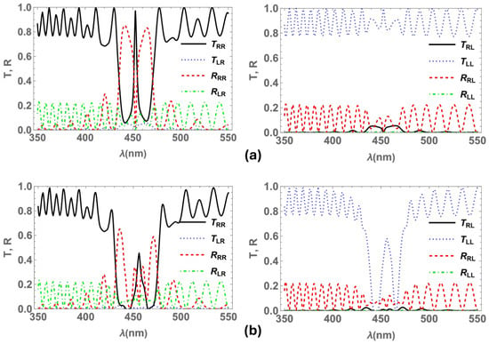
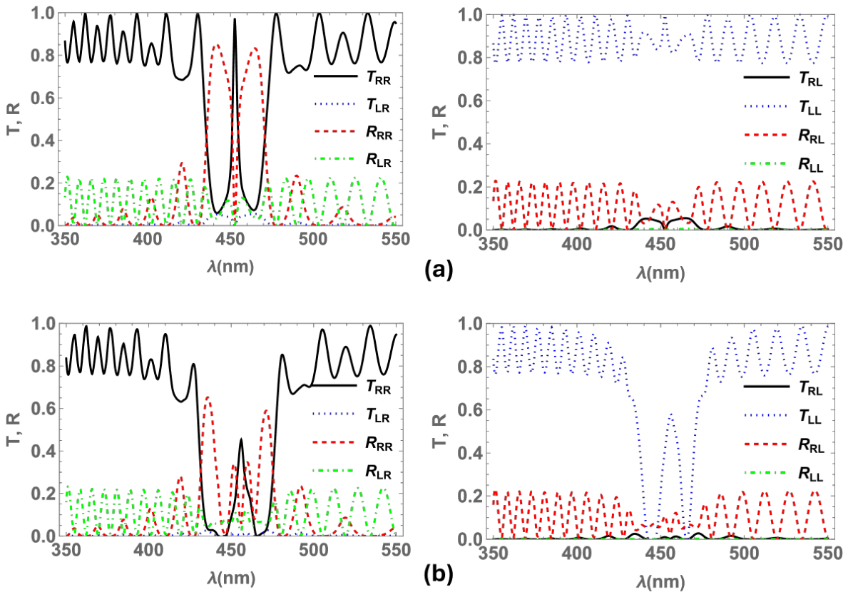
Figure 2a shows the transmittance and reflectance spectra at normal incidence for right- and left-circularly polarized light impinging on an NSCM with a twist defect in the center of the slab and pitch nm. The spectra display the usual twist defect mode band in the center of the circular Bragg band of the chiral structure for the transmission and reflection . Whereas, in Figure 2b the reflection spectrum exhibits that the band with the central defect mode splits into four distinct reflection bands when metallic nanoballs are randomly dispersed in the NSCM. Conversely, no splitting is observed in the transmission spectrum because the two bandgaps induced by the silver particles do not overlap with the defect mode peak. Furthermore, the intensity of both bands decreases due to the absorption of the silver inclusions. Here, for the chiral medium without either a twist defect or metallic inclusions, the band edges are located at nm and nm, where and . While the band edges are determined solely by the pitch and permittivities of the SCM when the structure is free of metallic nanoparticles, introducing metallic inclusions modifies the effective dielectric constants according to Equation (1). Consequently, the band edges, bandwidth, and central wavelength of the Bragg band become dependent on both the filling fraction and the frequency of the incident light.
Figure 2.
Transmittances and reflectances at normal incidence of light for a right-handed NSCM with a twist defect in the center of the slab and pitch nm. (a) Spectra for filling factor (no inclusions). (b) Spectra for (with metallic inclusions). The figures on the left (right) correspond to RCP (LCP) incident electromagnetic waves: RCP (black line) and LCP (blue dotted line) transmittances; RCP (red dashed line) and LCP (green dot-dashed line) reflectances.
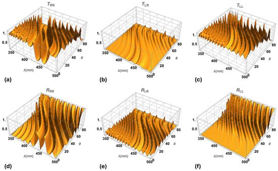
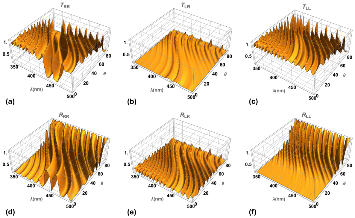
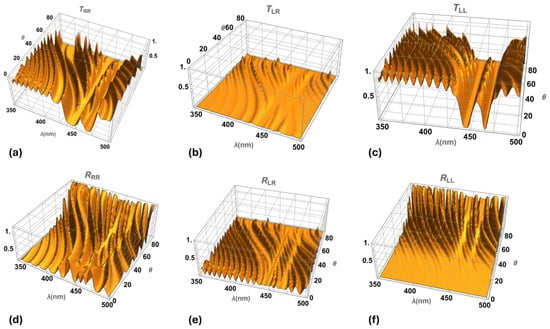
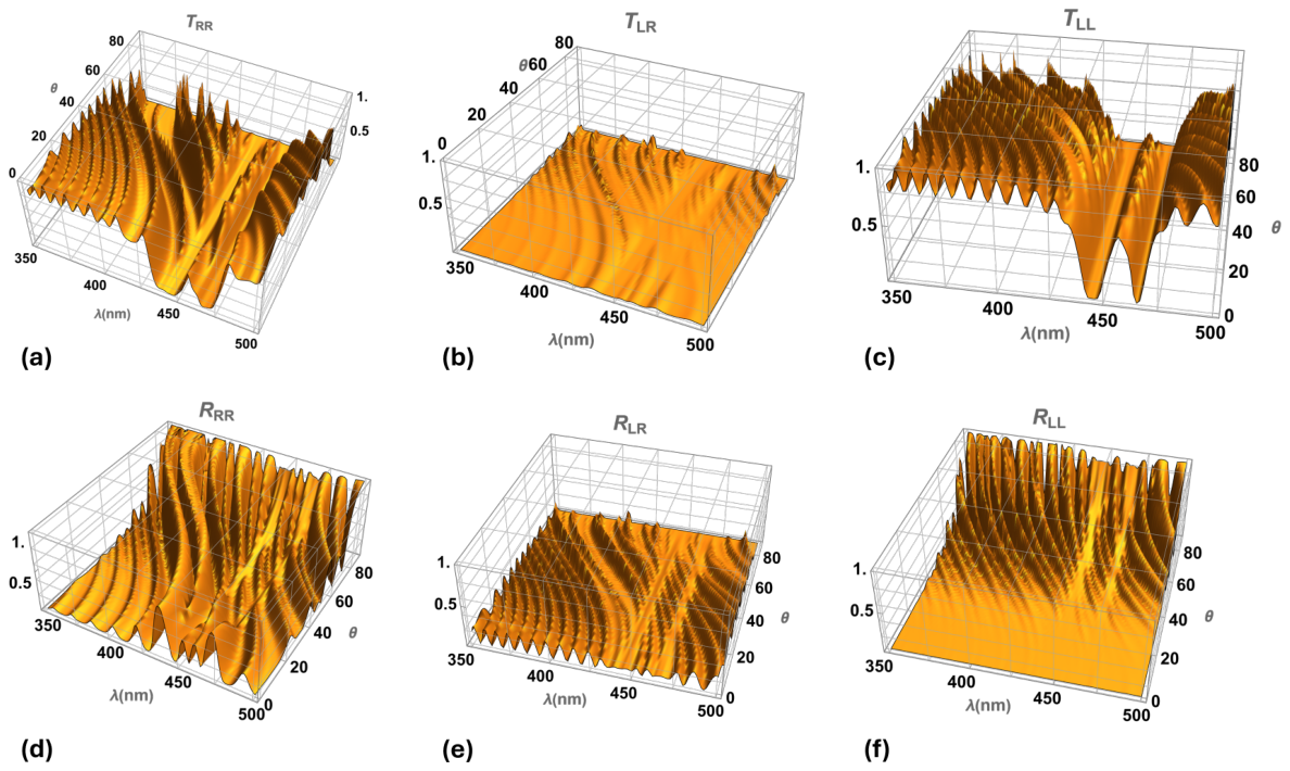
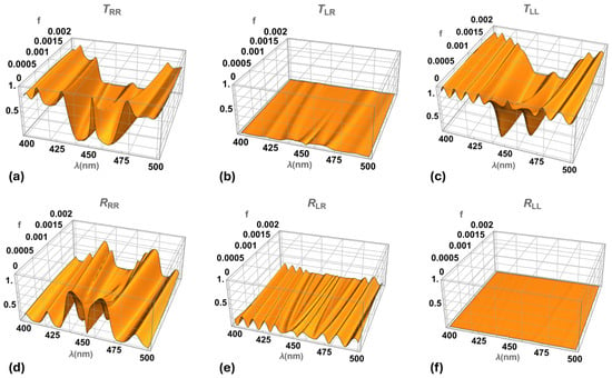
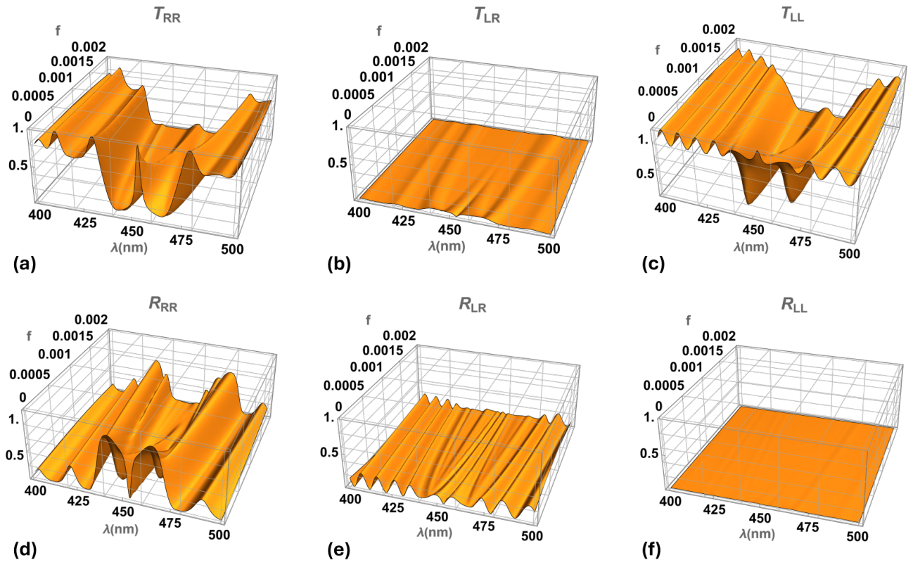
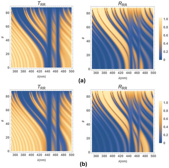
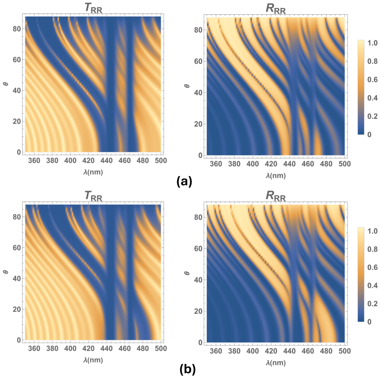
Figure 3 displays transmittances and reflectances as a function of the wavelength and the incidence angle of light , when circularly polarized light obliquely impinges on an NSCM with a twist defect in the center of the slab and no metallic inclusions, for the same material parameters as Figure 2. The spectra exhibit the usual defect mode band at the center of the circular Bragg band ( and spectra) and the blueshift of these bands as the incidence angle of light increases. Meanwhile, the dispersion and absorption induced by silver nanoballs give rise to two omnidirectional bandgaps in each of the transmission, , , and reflection, , spectra, where the center of these bands coincides with the resonant wavelengths of the silver nanoballs, approximately at nm and nm (see Figure 4), where and () are defined by Equation (2).
Figure 3.
Transmittances and reflectances as a function of the wavelength and light incidence angle , considering no metallic inclusions (filling factor ), for the same material parameters as Figure 2. As and to numerical accuracy, the plots of and are not displayed here.
Figure 4.
Transmittances and reflectances as a function of the wavelength and light incidence angle , for an NSCM considering inclusions of silver nanoballs (filling factor ), for the same material parameters as Figure 2. As and to numerical accuracy, the plots of and are not displayed here.
Note that there are no significant changes in the reflection , () and transmission spectra (), when adding metallic inclusions to the medium, other than two faint omnidirectional bands.
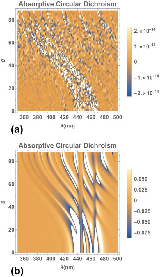
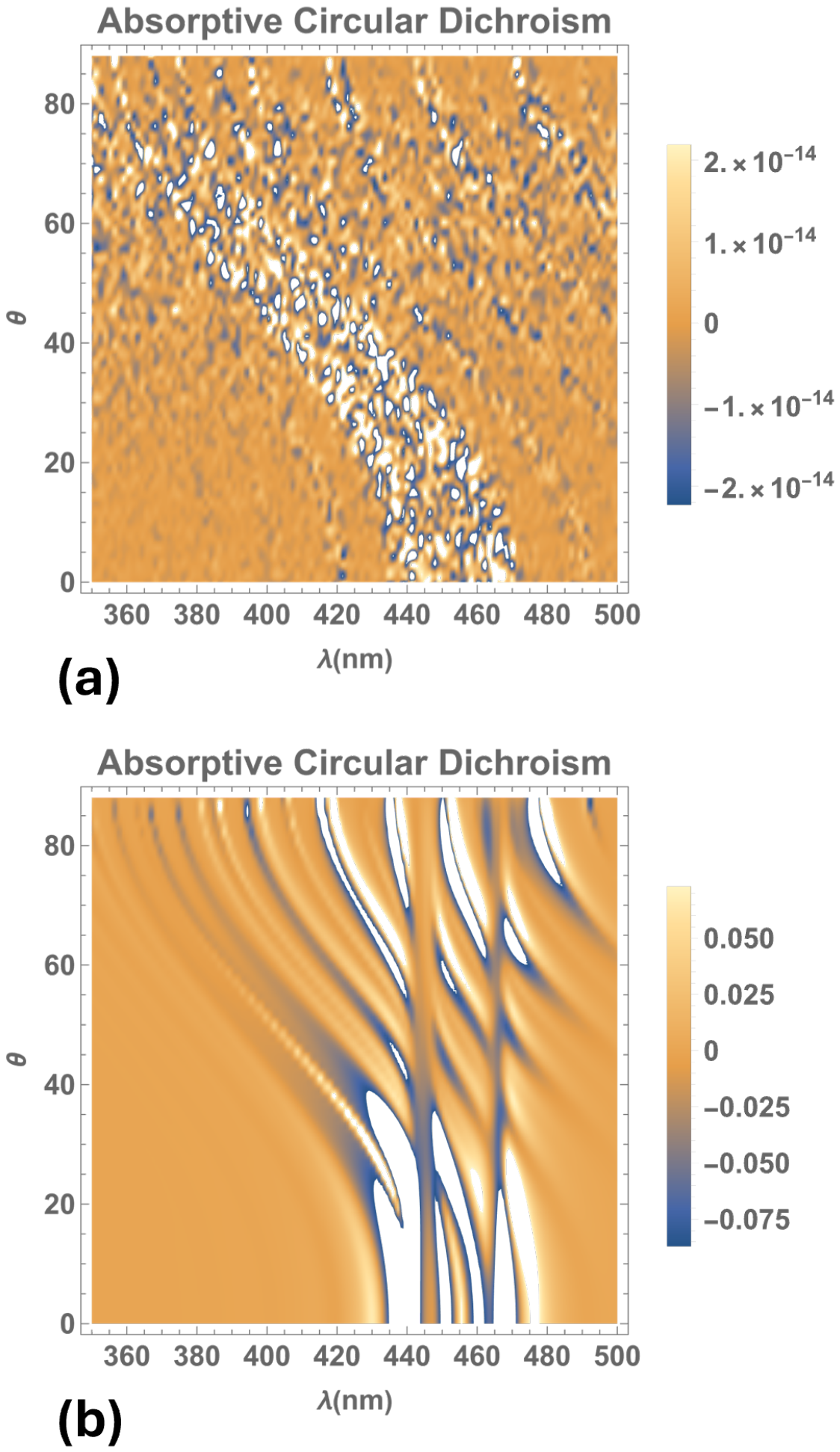
The Absorptive Circular Dichroism , where and are the absorptances for right- and left- circularly polarized incident waves, respectively, reveals the interplay between structural chirality and dissipation in the medium. Figure 5 shows the ACD as a function of the wavelength and the incidence angle of light for the same material parameters as Figure 2. Without metallic inclusions (Figure 5a), the contrast remains zero, with fluctuations of the order of attributable to numerical roundoff. The incorporation of a small nanosphere filling factor (Figure 5b) generates pronounced positive and negative spectral features, indicating preferential absorption of right- and left- circularly polarized incident waves, respectively. Near the resonant wavelengths of the silver nanospheres, several resonant branches shift toward shorter wavelengths as the incidence angle increases, whereas others exhibit weaker angular dispersion. This behavior is consistent with polarization-dependent variations in the internal electromagnetic field and the associated dissipative losses by the metallic inclusions. The sign reversals demonstrate that the preferentially absorbed polarization depends on both wavelength and incidence angle without changing structural handedness.
Figure 5.
Absorptive circular dichroism as a function of the wavelength and light incidence angle . The calculations use the same material parameters as in Figure 2 for two filling factors: (a) and (b) .
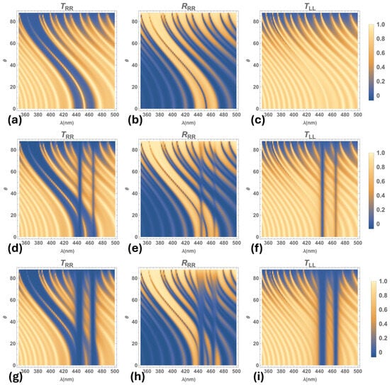
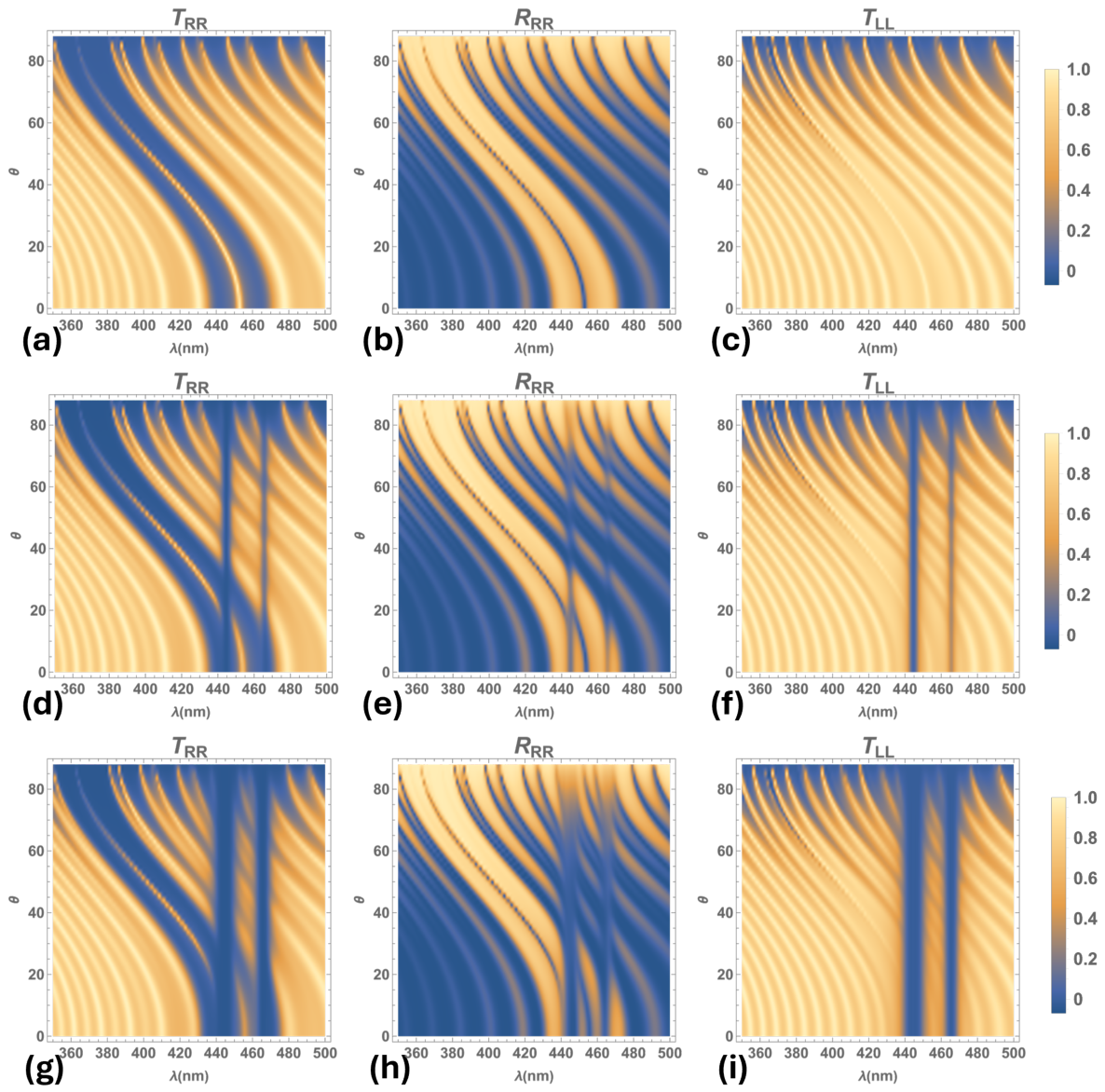
Figure 6 shows density plots of the relevant transmittances, , , and reflectance, , as function of the light incidence angle, , for the NSCM with a twist defect, for the same material parameters as Figure 2. The plots depict two different cases: (1) the medium with no metallic inclusions, (Figure 6a–c); and (2) the medium with silver inclusions for a filling factor of (Figure 6d–f) and (Figure 6g–i). We observe that when metallic nanospheres are included in the medium, the two omnidirectional band gaps appear in the transmission and reflection spectra, inside the Bragg band and on either side of the defect mode band at normal incidence, and they are broader and deeper as the silver nanoball fraction increases. These span a wavelength interval around the resonant wavelengths of the silver nanoballs in which the refractive indexes are complex numbers [15,16], hence, these omnidirectional bands are due to absorption and dispersion of the metallic inclusions in the NSCM. Thus, when the filling fraction increases, the absorption and dispersion of the medium increases around the resonant wavelengths of metallic inclusions. Additionally, calculations show that the center of the omnidirectional bandgaps slightly redshifts as the filling factor increases. Notice that although a dependence exists between the resonant wavelengths , and the filling factor, the center of the omnidirectional bandgaps are approximately at nm and nm for all the values of f considered in this study.
Figure 6.
Density plots of co-polarized transmittances, , , and reflectance, , as function of the angle of incidence . No metallic nanoballs included: (a–c) filling fraction . Silver nanoballs included: (d–f) , and (g–i) , for the same material parameters as Figure 2.
We observe splitting of the reflection bands inside the Bragg band as long as at least one of the omnidirectional bandgaps overlaps with the Bragg band; see Figure 6d–i, where . At normal incidence of light, the omnidirectional bands are on each side of the twist defect mode band; however, as the light incidence angle increases, the Bragg band, along with the defect mode blueshift while the omnidirectional bands, due solely to the silver nanoballs inclusions, remain nearly at the same light wavelengths. Therefore, the overlap of those bands and the consequent splitting of the reflection bands is observed only when the light incidence angle is (see Figure 6), where there are up to four reflection bands inside the Bragg band.
Meanwhile, in the transmission spectrum, , of Figure 6d,g, the omnidirectional bandgaps are situated within the Bragg bandgap. They slightly overlap the defect mode transmission peak, without splitting or suppressing it. Nevertheless, the peak intensity diminishes due to intrinsic absorption and dispersion from the silver inclusions (see in Figure 7b,c). Furthermore, for the medium with metallic inclusions, we observe two omnidirectional bands in the transmission spectrum, , that broaden as the filling factor increases.
Figure 7.
Transmittance and reflectance for (a) , (b) , and (c) . The calculations use the same material parameters as in Figure 2 for three angles of incidence: (black line), (blue dotted line), and (red dashed line).
Figure 7, exhibits plots of transmission, , and reflection, , spectra for the material parameters mentioned above. Here, we considered the following values for the filling fraction of metallic nanospheres: (a) , (b) and (c) , at three light incidence angles: , and . Figure 7a shows that, for a medium without metallic inclusions and nm, the Bragg band spans approximately from nm to nm, with the -twist defect mode band located at its center. Both bands blueshift concurrently as the angle of incidence increases. For the medium with silver inclusions, the reflection bands split into four sub-bands at normal incidence. Increasing the concentration of metallic inclusions further enhances this band splitting (see in Figure 7b,c, black line). Nevertheless, the defect mode transmission peak is neither split nor suppressed by the insertion of metallic inclusions into the NSCM; it is merely attenuated due to a slight overlap with the omnidirectional absorption bands within the Bragg band.
On the other hand, for the medium containing metallic nanospheres at an angle of incidence , band splitting occurs in both the transmission and reflection spectra within the Bragg band. For a filling factor , we observe three attenuated, narrow transmission bands, two well-defined reflection bands, and one minor reflection band (see Figure 7b, blue doted line). Meanwhile, for a filling factor , three attenuated, narrow transmission bands and two well-defined reflection bands are observed (see Figure 7c, blue dotted line). Thus, the intensity of the transmission and reflection bands diminish as the filling factor increases, for and . Nonetheless, for , the intensity of these bands does not decrease with an increase in the concentration of metallic inclusions, and no band splitting occurs because the Bragg band and omnidirectional bandgaps no longer overlap.
Figure 8 displays transmittances and reflectances as a function of the filling factor f at normal incidence. We observe the defect mode band at the center of the Bragg band, which rapidly diminishes as the filling factor increases (see and spectra in Figure 8a,d. Figure 8c displays the effect on the transmission due to the absorption caused by the metallic inclusions that generate two omnidirectional bands at the resonant wavelengths of the silver inclusions. We observe splitting of the reflection bands in the presence of metallic inclusions in the medium. Moreover, high reflection persists at the edges of the Bragg band, which broadens as the filling factor increases (see the spectrum in Figure 8d). Note that the remaining optical spectra —, and (Figure 8b,e,f)— are not significantly different from the plots of the medium without defect, which are reported in Ref. [15].
Figure 8.
Transmittances and reflectances as a function of filling factor f at normal incidence (), using the same material parameters as in Figure 2. As and to numerical accuracy, the plots of and are not displayed here.
Figure 9 displays plots of the transmission and reflection spectra as a function of the angle of incidence . In Figure 9a, we observe that for a medium with a pitch value of nm and a filling factor , at normal incidence, both omnidirectional bandgaps are located inside the Bragg band and on each side of the defect mode band for . This Bragg band spans from approximately 430 nm to 477 nm, and it broadens as the filling factor increases. The reflection band splits into up to four bands, whereas no splitting is observed for the transmission peak. At oblique incidence, the defect mode transmission band does not split; instead, it diminishes as the filling factor increases. This defect mode transmission band is neither split nor removed by the omnidirectional bands at normal incidence because, although both bands lie within the Bragg band, they barely overlap.
Figure 9.
Density plots of transmittance and reflectance as a function of the angle of incidence for a filling fraction of the included silver nanoballs. The calculations use the same material parameters as in Figure 2 for two values of pitch: (a) nm, and (b) nm.
In Figure 9b, we observe reflection and transmission spectra for the medium with nm and , where only the omnidirectional bandgap at nm lies inside the Bragg band beside the transmission peak at normal incidence. Here, there are up to three transmission bands as well as up to three reflection bands. Moreover, the Bragg band and the omnidirectional bandgaps cease to overlap when the incidence angle of light is approximately for a medium with nm and for nm (see Figure 9a,b). We observe that, at larger incidence angles, the blueshift of the Bragg band completely separates these bands, preventing any splitting of the transmission and reflection bands.
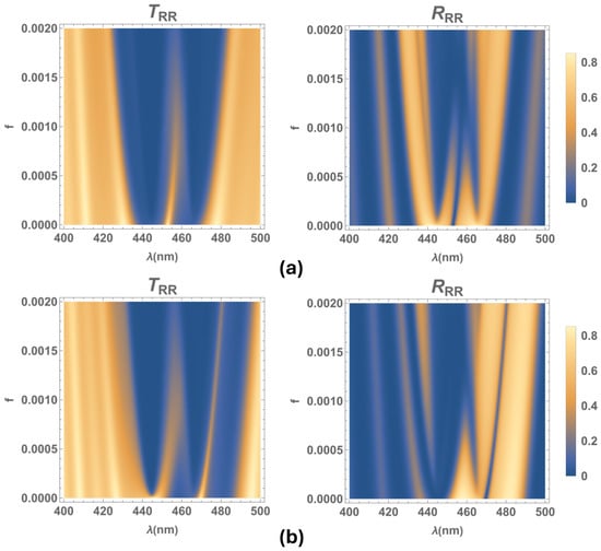
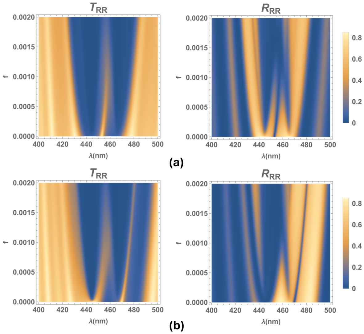
Figure 10 exhibits the density plots of transmittance and reflectance as a function of the filling factor f at normal incidence for two pitch values: (a) nm and (b) nm. Figure 10a shows that, for nm and , the transmission spectral peak of the twist defect is located at the center of the Bragg band. Owing to the overlap of this band with the omnidirectional bands at nm and nm, the Bragg reflection band splits into four sub-bands for filling factor values within approximately . Within this range, the intensity of the bands at the edges of the Bragg band remains high as the filling factor increases. While, for the medium with nm and , similar results are observed (see Figure 10b); here, the optical band spans from approximately 450 nm to 490 nm. In contrast, for the medium without a twist defect or inclusions, the edges of the Bragg band are nm () and nm (). Notice that the omnidirectional band with a central wavelength at nm lies outside the Bragg band. The reflection band at longer wavelengths has the highest intensity and splits when coupled with the resonant wavelength of metallic inclusions at nm. Meanwhile, the transmission bandgap broadens due to the overlap with the absorption band at shorter wavelengths.
Figure 10.
Density plots of transmittance and reflectance as a function of the filling factor f at normal incidence of light. The calculations use the same material parameters as in Figure 2 for two pitch values: (a) nm, and (b) nm.
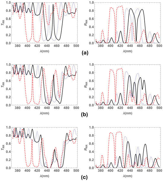
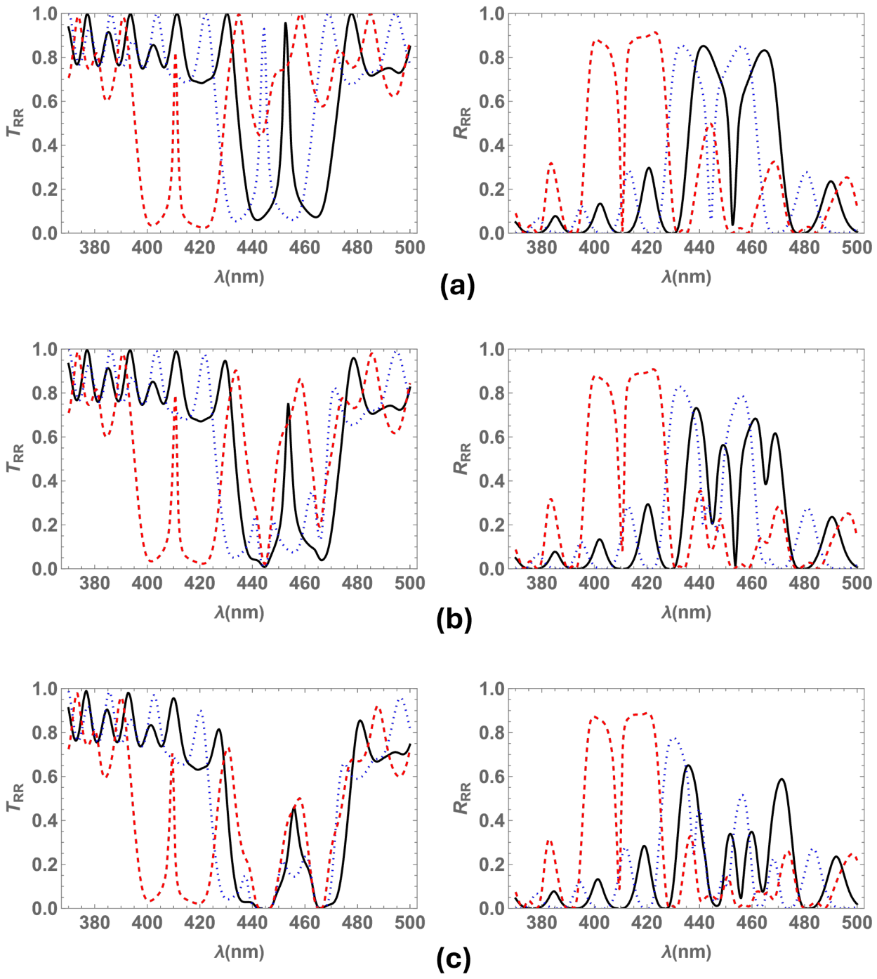
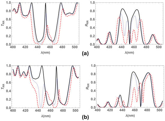
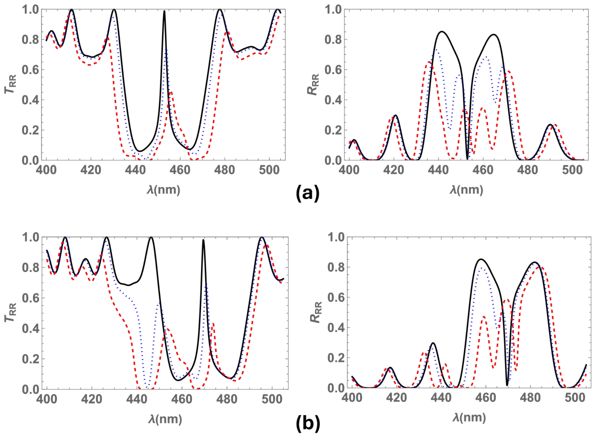
Figure 11 shows plots of transmittance and reflectance at normal incidence for different filling factor values (, , ) and pitch values ( nm, and nm). For the medium with nm (see Figure 11a), both omnidirectional bandgaps lie inside the Bragg band and alongside the defect mode peak, which diminishes without splitting as the filling factor increases. Furthermore, owing to the coupling between the Bragg band and the omnidirectional bandgaps, each reflection band splits within the Bragg band. Thus, four reflection bands emerge inside the Bragg band.
Figure 11.
Transmittance and reflectance at normal incidence. The calculations use the same material parameters as in Figure 2 for two pitch values: (a) nm and (b) nm. Three values of filling fraction are considered: (black solid line), (blue dotted line), and (red dashed line).
Figure 11b shows that the Bragg band redshifts as the pitch increases, as expected, when comparing the spectra for nm and nm, whereas the omnidirectional absorption bands remain at the same wavelengths. Here, the omnidirectional band at shorter wavelengths lies outside the Bragg band, while the other overlaps it (see Figure 9b), splitting the reflection band at the resonant wavelength of nm. Hence, the reflection spectrum displays three bands for each filling factor value, where the band with the highest intensity is located at longer wavelengths, and its intensity decreases as the filling factor increases.
The spectra show that splitting is enhanced as the filling fraction of silver nanospheres increases in the NSCM, consistent with other nanocomposites doped with metallic inclusions [13,14]. For a filling fraction of , the transmission spectrum shows two narrow transmission bands inside a broader bandgap, where (430, 490) nm, approximately (Figure 11b red dashed line).
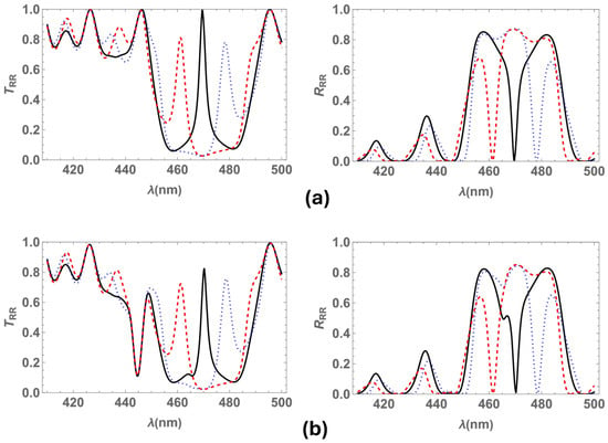
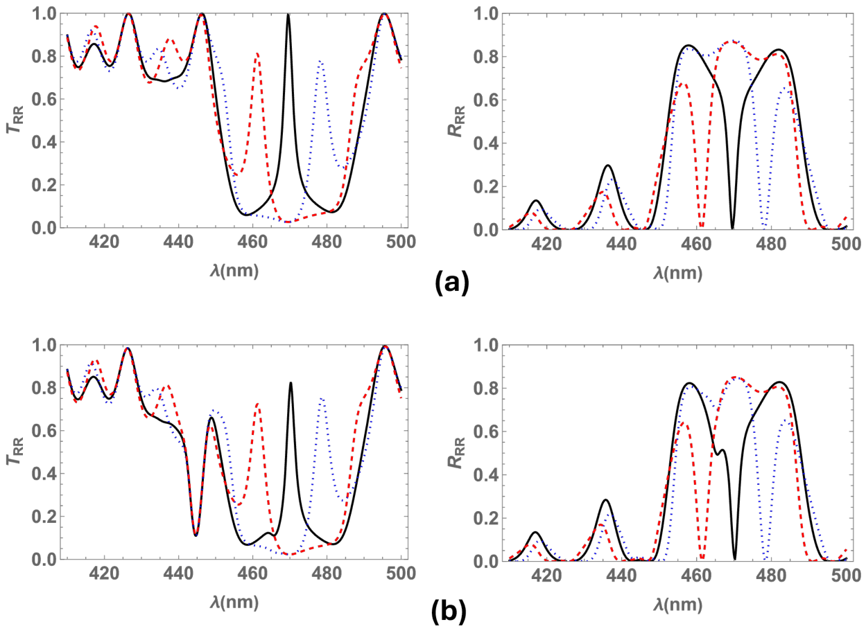
Figure 12 displays transmittance and reflectance at normal incidence for a pitch value of nm and different values of twist defect angles (, , ). To facilitate comparison, Figure 12a shows and for the medium without metallic inclusions, whereas Figure 12b shows the spectra for the medium with silver nanospheres at . In the latter case, a twist defect mode peak is observed inside the Bragg band, along with an omnidirectional band outside the Bragg regime at nm. Concurrently, the second omnidirectional band lies inside the Bragg band at nm. This latter band is adjacent to the transmission peak for , and ; hence, it is not discernible. The transmission spectrum shows that the defect mode peak diminishes at for and , whereas it maintains nearly the same intensity for the medium with . Additionally, for and , two well defined transmission peaks emerge inside a wider bandgap within the approximate range of nm. This behavior is consistent with that of a chiral medium featuring two twist defects uniformly distributed along its helical axis. In contrast, for the medium with silver nanospheres and a twist defect, two slightly overlapped transmission bands appear inside the Bragg band (see Figure 12b, red dashed line). The reflection spectrum exhibit a slightly broader bandgap at nm, for and (compared with , ).
Figure 12.
Transmittance and reflectance at normal incidence, using the same material parameters as in Figure 2 and a pitch of nm, for two values of filling fraction: (a) , and (b) . The calculations consider twist defect angles of (black solid line), (blue dotted line), and (red dashed line).
Moreover, within the transmission band of the medium containing metallic inclusions, two distinct peaks are observed, whose separation can be tuned by varying the twist defect angle. For a medium with a twist defect, these two peaks overlap.
Table 1 provides a comparative overview of the effects of structural parameters and metallic inclusions on the optical response of the NSCM.
Table 1.
Influence of structural and metallic parameters on the optical response of the NSCM.
The physical mechanisms identified in this study are not exclusive to silver inclusions and can be generalized to other metallic nanoparticles randomly dispersed within a structurally chiral medium, provided that their plasmonic resonances spectrally overlap with the circular Bragg band. For instance, gold nanospheres embedded in the medium with the specified structural and dielectric parameters exhibit plasmonic resonances at wavelengths nm and nm. By tuning the helical pitch, the circular Bragg band of the nanoparticle-free structure can be shifted to overlap with these resonances, enabling their spectral interplay. Specifically, for a pitch nm, the Bragg band spans the wavelength interval nm, where the interaction between plasmonic resonances and the photonic bandgap may give rise to modified transmission and reflection spectra.
4. Conclusions
In summary, we studied optical spectra for circularly polarized light that normally and obliquely impinges on a nanocomposite structurally chiral medium, which locally possesses a point group symmetry, with randomly dispersed metallic nanoballs and a twist defect in the center of the slab. We numerically compute the optical spectra by means of the piecewise uniform approximation of the transfer matrix method.
The spectra exhibit one twist defect mode band within the Bragg band of the chiral structure and two omnidirectional bandgaps arising from the dispersion and absorption effects of the silver inclusions. The centers of these omnidirectional bands coincide with the resonant wavelengths of the silver nanospheres. Furthermore, these latter bands become deeper and broader as the filling fraction of silver inclusions increases; near the resonant wavelengths, the absorption and dispersion of the medium are enhanced by the higher concentration of metallic inclusions.
The spectra show that the omnidirectional bandgaps that appear for the medium with metallic inclusions can split and broaden the reflection Bragg band; they also split or diminish the transmission twist defect peak, yielding up to four reflection bands and up to three transmission bands. This effect is due to the coupling between the transmission peak and the omnidirectional bands generated by the absorption and dispersion of the metallic inclusions.
The Bragg band blueshifts as the light incidence angle increases and redshifts as the pitch increases, whereas the omnidirectional absorption bands remain fixed at the same wavelengths. Therefore, overlapping between the Bragg band and the omnidirectional bands is observed only for incidence angles ; for angles of incidence , these bands are completely decoupled, and no modification of the spectra due to the metallic inclusions is observed. Likewise, the coupling between bands can be tuned by selecting appropriate values for either the incidence angle or the pitch.
Moreover, for a structurally chiral medium with a twist defect and metallic nanospheres, The transmission spectrum can exhibit two peaks inside a broadened bandgap, where the separation of the peaks can be controlled via the twist defect angle. The overlapping of bands can be tuned by properly selecting the pitch, incidence angle, twist defect angle, and filling fraction of metallic inclusions, consequently modifying the optical spectra.
The research presented herein shows a novel photonic device with potential applications as an optical resonator, a circular polarizer, and a wavelength filter. The transmission and reflection spectra of this device can be controlled by selecting appropriate material parameters and light incidence angles. Furthermore, these photonic media could be utilized in the development of sensors for metallic particles in fluids. In particular, while the specific set of parameters employed in this work yields interesting results in the violet and blue regions of the electromagnetic spectrum, they can be suitably adjusted to meet specific requirements in other spectral domains.
Author Contributions
Conceptualization, L.O.P.; methodology, L.O.P. and C.G.A.; software, L.O.P. and C.G.A.; validation, L.O.P. and C.G.A.; formal analysis, L.O.P. and C.G.A.; investigation, L.O.P. and C.G.A.; resources, L.O.P. and C.G.A.; data curation, L.O.P. and C.G.A.; writing—original draft preparation, L.O.P.; writing—review and editing, L.O.P. and C.G.A.; visualization, L.O.P. and C.G.A.; supervision, L.O.P. and C.G.A.; project administration, L.O.P. and C.G.A.; funding acquisition, C.G.A. All authors have read and agreed to the published version of the manuscript.
Funding
This research received no external funding.
Data Availability Statement
The original contributions presented in this study are included in the article. Further inquiries can be directed to the corresponding author.
Acknowledgments
Carlos G. Avendaño acknowledges financial support from CCyT UACM through grant UACM CCYT-2026-CON-11.
Conflicts of Interest
The authors declare no conflicts of interest.
References
- De Gennes, P.G.; Prost, J. The Physics of Liquid Crystals; Clarendon Press: Oxford, UK, 1993. [Google Scholar]
- Warner, M.; Terentjev, E.M. Liquid Crystal Elastomers; Clarendon Press: Oxford, UK, 2003. [Google Scholar]
- Lakhtakia, A.; Messier, R. Sculptured Thin Films: Nanoengineered Morphology and Optics; Spie Press: Washington, DC, USA, 2005. [Google Scholar]
- Faryad, M.; Lakhtakia, A. The circular Bragg phenomenon. Adv. Opt. Photon. 2014, 6, 225–292. [Google Scholar] [CrossRef] [Scilit]
- Lakhtakia, A.; Venugopal, V.C.; McCall, M.W. Spectral holes in Bragg reflection from chiral sculptured thin films: Circular polarization filters. Opt. Commun. 2000, 177, 57–68. [Google Scholar] [CrossRef] [Scilit]
- Hodgkinson, I.J.; Wu, Q.H.; Thorn, K.E.; Lakhtakia, A.; McCall, M.W. Spacerless circular-polarization spectral-hole filters using chiral sculptured thin films: Theory and experiment. Opt. Commun. 2000, 184, 57–66. [Google Scholar] [CrossRef] [Scilit]
- Matsuhisa, Y.; Ozaki, R.; Yoshino, K.; Ozaki, M. High Q defect mode and laser action in one-dimensional hybrid photonic crystal containing cholesteric liquid crystal. Appl. Phys. Lett. 2006, 89, 101109. [Google Scholar] [CrossRef] [Scilit]
- Hsiao, Y.C.; Hou, C.T.; Zyryanov, V.Y.; Lee, W. Multichannel photonic devices based on tristable polymer-stabilized cholesteric textures. Opt. Express 2011, 19, 23952–23957. [Google Scholar] [CrossRef] [Scilit]
- Serra, F.; Matranga, M.A.; Ji, Y.; Terentjev, E.M. Single-mode laser tuning from cholesteric elastomers using a notch band-gap configuration. Opt. Express 2010, 18, 575–581. [Google Scholar] [CrossRef] [Scilit]
- Mota, A.E.; Palomares, L.O.; Reyes, J.A. Mechanically controlled defect mode in cholesteric elastomers. Appl. Phys. Lett. 2010, 96, 081906. [Google Scholar] [CrossRef] [Scilit]
- Avendaño, C.G.; Reyes, J.A. Mechanically tuned defect-mode multiplet for cholesteric photonic elastomers. Phys. Rev. E 2012, 85, 021702. [Google Scholar] [CrossRef] [Scilit]
- Avendaño, C.G.; Reyes, J.A. Elastic dependence of defect modes in one-dimensional photonic crystals with a cholesteric elastomer slab. Photonics Nanostruct. Fundam. Appl. 2018, 30, 30–38. [Google Scholar] [CrossRef] [Scilit]
- Vetrov, S.Y.; Avdeeva, A.Y.; V., T.I. Spectral properties of a one-dimensional photonic crystal with a resonant defect nanocomposite layer. J. Exp. Theor. Phys. 2011, 113, 755. [Google Scholar] [CrossRef] [Scilit]
- Vetrov, S.Y.; Pyatnov, M.V.; Timofeev, I.V. Photonic defect modes in a cholesteric liquid crystal with a resonant nanocomposite layer and a twist defect. Phis. Rev. E 2014, 90, 032505. [Google Scholar] [CrossRef] [Scilit]
- Mendoza, J.; Reyes, J.A.; Avendaño, C.G. Optical band gap in a nanocomposite structurally chiral medium. Phys. Rev. A 2016, 94, 053839. [Google Scholar] [CrossRef] [Scilit]
- Avendaño, C.G.; Palomares, L.O. Omnidirectional narrow optical filters for circularly polarized light in a nanocomposite structurally chiral medium. Appl. Opt. 2018, 57, 3119–3125. [Google Scholar] [CrossRef] [Scilit]
- Pitruzzello, G.; Krauss, T.F. Photonic crystal resonances for sensing and imaging. J. Opt. 2018, 20, 073004. [Google Scholar] [CrossRef] [Scilit]
- Ghorani, N.; Madani, A.; Entezar, S.R. Real-time biosensor application of structurally chiral medium for detection and sensing of plasma in human blood. Phys. Scr. 2023, 98, 055518. [Google Scholar] [CrossRef] [Scilit]
- Ghorani, N.; Madani, A.; Entezer, S.R. Detection of the blood hemoglobin using an electro-optical biosensor based on a structurally chiral medium. Int. J. Biophoton. Biomed. Eng. 2023, 3, 23–29. [Google Scholar]
- Fiallo, R.A.; Horn, M.W.; Lakhtakia, A. Polarization-universal bandgaps realized with chiral sculptured thin films. J. Opt. Soc. Am. B 2022, 39, 2697–2704. [Google Scholar] [CrossRef] [Scilit]
- Dimitrov, B.; Bukharina, D.; Poliukhova, V.; Nepal, D.; McConney, M.E.; Bunning, T.J.; Tsukruk, V.V. Printed Twisted Thin Films with Near-Infrared Bandgaps and Tailored Chiroptical Properties. ACS Appl. Opt. Mater. 2024, 2, 2540–2550. [Google Scholar] [CrossRef] [Scilit]
- Lakhtakia, A. Geometric phase in plane-wave transmission by a dielectric structurally chiral slab with a central phase defect. Phys. Rev. A 2024, 109, 043517. [Google Scholar] [CrossRef] [Scilit]
- Zaplotnik, J.; Mur, U.; Muševič, I.; Ravnik, M. Photonic defect modes in cholesteric liquid crystal resonators with embedded isotropic layers. Opt. Express 2024, 32, 34564–34581. [Google Scholar] [CrossRef] [Scilit]
- Wu, W.; Pauly, M. Chiral plasmonic nanostructures: Recent advances in their synthesis and applications. Mater. Adv. 2022, 3, 186–215. [Google Scholar] [CrossRef] [Scilit]
- Zhang, X.; Xu, Y.; Valenzuela, C.; Zhang, X.; Wang, L.; Feng, W.; Li, Q. Liquid crystal-templated chiral nanomaterials: From chiral plasmonics to circularly polarized luminescence. Light Sci. Appl. 2022, 11, 223. [Google Scholar] [CrossRef] [Scilit]
- Qi, X.; Pérez, L.A.; Mendoza-Carreño, J.; Garriga, M.; Alonso, M.I.; Mihi, A. Chiral plasmonic superlattices from template-assisted assembly of achiral nanoparticles. Nat. Commun. 2025, 16, 1687. [Google Scholar] [CrossRef] [Scilit]
- Reyes, G.; Reyes, J.A. Omnidirectional optical spectra for a nanocomposite cholesteric elastomer. J. Phys. Condens. Matter 2019, 31, 325701. [Google Scholar] [CrossRef] [Scilit]
- Reyes, G.; Reyes, J.A. Optical spectra for a cholesteric elastomer doped with metallic nanospheres with an inversion defect. J. Mod. Opt. 2023, 70, 253–264. [Google Scholar] [CrossRef] [Scilit]
- Shirin, S.; Madani, A.; Entezar, S.R. Tunable lateral shift of the reflected optical beams from a nanocomposite structurally chiral medium. Opt. Mater. 2020, 107, 110026. [Google Scholar] [CrossRef] [Scilit]
- Shirin, S.; Madani, A.; Roshan Entezar, S. Polarization switchable lateral shift of the transmitted and reflected defect modes from a structurally chiral medium with a twist defect. Phys. Scr. 2025, 100, 085567. [Google Scholar] [CrossRef] [Scilit]
- Lakhtakia, A.; McCall, M.W.; A., S.J.; Wu, Q.H.; Hodgkinson, I.J. Sculptured-thin film spectral holes for optical sensing of fluids. Opt. Commun. 2001, 194, 33–46. [Google Scholar] [CrossRef] [Scilit]
- Sherwin, J.A.; Lakhtakia, A. Nominal model for the optical response of a chiral sculptured thin film infiltrated with an isotropic chiral fluid. Opt. Commun. 2002, 214, 231–245. [Google Scholar] [CrossRef] [Scilit]
- Chuang, S.L. Physics of Photonic Devices; John Wiley & Sons: Hoboken, NJ, USA, 2009. [Google Scholar]
- Mackay, T.G.; Lakhtakia, A. The Transfer-Matrix Method in Electromagnetics and Optics; Morgan & Claypool Publishers: San Rafael, CA, USA, 2020. [Google Scholar]

Disclaimer/Publisher’s Note: The statements, opinions and data contained in all publications are solely those of the individual author(s) and contributor(s) and not of MDPI and/or the editor(s). MDPI and/or the editor(s) disclaim responsibility for any injury to people or property resulting from any ideas, methods, instructions or products referred to in the content. |
© 2026 by the authors. Licensee MDPI, Basel, Switzerland. This article is an open access article distributed under the terms and conditions of the Creative Commons Attribution (CC BY) license.