


Abstract
To address the core challenges of low energy utilization efficiency and limited range in front-wheel-drive electric vehicles (FWD EVs), this study proposes a dynamic series braking energy recovery strategy featuring adaptive braking force distribution and multi-factor correction. A comprehensive simulation model integrating five core modules—Cycle, Driver, Controller, Vehicle, and Display—was developed using Matlab/Simulink, combining the dynamic series recovery strategy with traditional parallel recovery strategies. Model reliability was validated through chassis dynamometer test data (maximum error ≤ 3.2%), followed by simulation comparisons under CLTC conditions. Results demonstrate that compared to parallel strategies, the dynamic series approach increases range by 25.8% (from 318 km to 400 km). Key innovations include real-time adaptive front axle braking coefficients based on braking intensity and a correction mechanism integrating vehicle speed and state of charge (SOC), achieving a balance between recovery efficiency, braking stability, and battery protection. This study provides actionable design guidance for FWD EV powertrain optimization while establishing a validated regenerative braking simulation framework.
1. Introduction
Braking energy recovery in electric vehicles is an effective measure to improve energy utilization and overall economy, which makes it have incomparable advantages over traditional vehicles: it can not only improve the energy utilization rate, reasonably use the energy that would have been wasted to extend the cruising range of the vehicle, but also alleviate the issue of weak power during vehicle startup, and also reduce the consumption and wear of the basic braking system and braking heat, reduce noise and alleviate thermal recession, thus optimizing the braking performance of the vehicle, improving braking stability and prolonging the service life of the brake [1]. By optimizing the energy recovery strategy, the overall performance of electric vehicles can be improved, making them more suitable for diversified driving needs [2]. This research is not only of great significance to environmental protection and economic benefits, but also can promote the progress of related technologies and the transformation and upgrading of the automobile industry [3].
Using Simulink to simulate a pure electric vehicle model for studying braking energy recovery allows researchers to test extreme conditions without damaging the hardware, avoiding the danger caused by possible problems in the testing process, reducing the number of physical prototypes and reducing the research and development cost, especially in the early design stage [4], and at the same time, the simulation environment allows researchers to accurately control the experimental conditions, which may be difficult to achieve in the real environment, making it easier to alter parameters and conduct ‘what-if’ analyses [5,6]. Once the simulation model is created, it can be used repeatedly to test different scenarios and assumptions, and a large amount of data can be generated, which is helpful to deeply understand the dynamic behavior of the system and facilitate the subsequent data analysis [7].
In practical applications, the control strategy of the regenerative braking system has also been widely studied. Ai, Y.Y. et al. [8] designed an optimal control strategy for regenerative braking energy recovery of battery electric vehicles based on the electro-mechanical braking system, which effectively improves the energy recovery efficiency of a single braking system but is limited to the structural constraints of electro-mechanical braking systems—failing to consider the collaborative complementarity with hydraulic braking systems, and thus cannot adapt to complex braking scenarios requiring multi-system synergy. The team of Chen, D.L. [9] proposed a hierarchical control strategy for regenerative braking energy recovery of distributed drive battery electric vehicles based on working condition recognition. This strategy optimizes energy recovery effects under complex drive configurations through hierarchical logic, yet its core design is tailored to distributed drive architectures, resulting in poor adaptability to mainstream front-wheel-drive configurations; additionally, the working condition recognition algorithm relies on a large amount of pre-calibrated data, lacking real-time adaptability to unforeseen working conditions. Cao, L.L. et al. [10] specially developed a regenerative braking energy recovery strategy adapted to the structural characteristics of battery electric vehicles with front and rear axle dual motors, giving full play to the advantages of coordinated recovery of dual motors. However, the strategy overly focuses on the collaborative control of dual motors and ignores the dynamic constraints of battery SOC and vehicle speed on recovery intensity, which may lead to battery overcharging risks under high SOC conditions or poor driving smoothness at low speeds. Peng, S.Y. [11] focused on the goal of energy recovery and constructed a control strategy for the EHB-motor composite braking system of electric vehicles, realizing the coordinated optimization of electro-hydraulic braking and motor regenerative braking. Nevertheless, the strategy adopts a fixed braking force distribution ratio and lacks adaptive adjustment based on braking intensity; it also fails to establish a dynamic correction mechanism linked to real-time vehicle status, resulting in insufficient optimization of recovery efficiency under different braking severity levels. Lu, Y. [12] focused on the cooperative control strategy of the electromechanical regenerative braking energy recovery system of battery electric vehicles, improving the stability and efficiency of energy recovery through multi-system collaboration. However, the study mainly emphasizes the cooperative logic between electromechanical systems and does not consider the coupling impact of tire-road adhesion conditions on braking force allocation, which may compromise braking stability when the road surface adhesion coefficient is low; furthermore, the strategy’s control parameters are calibrated for specific vehicle models, lacking universality for different vehicle parameter configurations.
While the aforementioned studies have significantly advanced regenerative braking technologies, a critical gap remains in the literature: a persistent trade-off between architectural complexity and real-time dynamic adaptability. Existing methods heavily reliant on dual-motor or distributed drive architectures lack universality for the mainstream front-wheel-drive (FWD) market. Conversely, composite braking strategies for FWD vehicles often employ static allocation ratios or highly complex intelligent algorithms. These approaches not only demand substantial computational resources but also frequently overlook the coupled dynamic constraints of low-speed drivability and high-SOC battery protection.
To address these limitations, the novelty of this study lies in developing a low-complexity, highly adaptive dynamic series recovery strategy specifically optimized for FWD EVs. Unlike existing static models, the proposed strategy introduces a real-time adaptive front-axle braking coefficient mapped directly to braking intensity. Furthermore, it integrates a novel multi-factor dynamic correction mechanism (combining real-time vehicle speed and SOC constraints). This approach achieves the high regenerative efficiency typically associated with complex algorithmic models, but utilizes a simplified control logic that ensures superior real-time responsiveness, braking stability, and battery safety.
2. Literature Review
2.1. Regenerative Braking Systems and Control Strategies
The regenerative braking systems (RBS) have now become a key technology in enhancing the energy efficiency of electric cars (EVs) and hybrid electric cars (HEVs). Such systems enable the regeneration of energy in the vehicle during braking by converting the motion of the car into electricity which is saved within the battery to be used at a later time. The operation greatly helps the range of the car, avoids wastage of energy and eliminates wear and tear of conventional brake system.
According to Szumska [5], regenerative braking has become widely popular over the past twenty years as one of the most important ways to improve the general efficiency of electric vehicles. With developments in control schemes, energy recovery models, and optimization algorithms, the performance of such systems has greatly enhanced. A regenerative braking system works generally on the principle of using an electric drive to slow a car down and convert kinetic power into electricity. The given technology has been shown to be useful in minimizing total energy use, extending vehicle range, and enhancing sustainability. Nonetheless, energy recovery optimization is still problematic when taking into account real world driving environments and particular vehicle configurations, including front-wheel-drive (FWD) systems.
Regenerative braking systems performance are highly affected by control methods which are implemented to control energy recovery. These strategies may all come under a few general categories, such as parallel, series, adaptive, rule-based, and optimization-based strategies. All these approaches are optimizing energy recovery to different extents, which depend on the particular driving conditions and the architecture of the vehicle.
2.1.1. Parallel Regenerative Braking
Parallel regenerative braking systems employ both regenerative braking and conventional hydraulic braking concurrently. Although such a strategy remains effective in the case of moderate decelerations, it cannot be applied as flexibly when trying to maximize energy recovery in cases involving a stronger deceleration. It is noted by Li et al. [13] that the recovery rate of energy in the parallel systems is typically constant and thus this restricts the ability to adapt the system. Furthermore, Qiu et al. [14] explain that with such a fixed rate of recovery it becomes difficult to achieve the best performance of the system at high levels of variation in driving conditions especially in the city where there is a lot of stop-and-go movement.
2.1.2. Series Regenerative Braking
The series regenerative braking system adjusts the braking force depending on the changes in the parameters of the real time parameters like vehicle speed and battery state of charge (SOC). Such dynamic changes lead to better energy recovery, particularly at higher rates of deceleration. As Zhou and Chen [15] show, series regenerative brakings systems can recover energy better than parallel ones, especially when frequent motor engagement is necessary. The series system can optimize energy recovery by changing the braking force dynamically so that it would not overload the hydraulic braking system.
2.1.3. Other Regenerative Braking Strategies
The adaptive strategies make use of machine learning and optimization algorithms that change the braking force depending upon several factors like the speed of the vehicle, battery state-of-charge (SOC), and other environmental elements. The strategies have important benefits when it comes to the energy recovery efficiency because they keep on keeping up with the actual conditions in which drivers drive their vehicles. Xie and Zhao [16] point to the prospects of adaptive strategies (including Particle Swarm Optimization (PSO)) to optimize the process of regenerative breaking. Nevertheless, they observe that there could be a high computational complexity needed to perform in real time, which might restrict the widespread applicability of the systems especially in low-cost automobiles.
The approach of rule-based strategies is based on a specific predetermined set of rules to define the amount of braking force and energy recovery. These strategies are easier to implement than adaptive ones but have lower flexibility levels. According to Kumar and Sharma [17], it is proposed that although the rule-based system performs well in a predictable driving environment, it fails to maximize the energy recovery during dynamically changing conditions or unpredictable situations. These systems can be applied in more straightforward driving scenarios, but fail in cases where complicated variables are present.
Strategies based on optimization, including game theory and PSO are intended to optimize energy recovery through sharing the braking forces of the regenerative braking system with each other and the hydraulic brakes. Zhou and Chen [15] explain that these strategies adaptively change the braking force to optimize the recovery of energy. Nonetheless, such approaches are frequently demanding in terms of calculations, so they can also be time-consuming when applied to a real-time system. Although highly efficient, they are usually limited to high-end systems or experimental ones because of the complexity.
2.2. Key Influencing Factors of Regenerative Braking
2.2.1. Energy Recovery Efficiency and Vehicle Performance
The effectiveness of energy recovery Efficiency is also one of the key factors to consider when assessing the quality of regenerative braking system. The greater efficiency of recovery is, the more energy can be stored, which lowers the total amount of energy used by the vehicle and increases the distance it can travel.
Szumska [5] and Li et al., [13] describe how series regenerative braking systems are able to attain up to 15 percent better energy recovery as opposed to parallel methods, especially at higher deceleration levels. The increase would be even more pronounced when the motor could be used more often to maximize efficiency of energy recovery. Efficiency of regenerative braking systems also relies greatly on driving circumstances. According to Kumar and Sharma [17], energy recovery varies depending on vehicle speed and battery SOC, and the faster the car goes, the higher rate of recovery it gets. But Chidambaram [18] notes that when the battery SOC is near full, recovery modes decrease braking force in order to prevent overcharging, which reduces the efficiency of energy recovery.
2.2.2. State of Charge (SOC) Management
SOC management is extremely important to energy recovery, and also to the lifetime of a vehicle battery. Optimal SOC management means that the battery is kept under safe conditions which would not lead to overcharging and consequently extend the life of the battery.
Chidambaram [18] highlights that in serial regenerative braking systems, the dynamism in changing braking effort depending on the battery state of charge will guarantee that the battery does not extend beyond the safety levels. It is especially crucial when it comes to preserving the health of the batteries in electric cars since overcharging them may have adverse effects on their lifespan.
Li et al., [13] claim that the management of SOC in real time optimizes regenerative braking and safeguards the battery against overcharging. It will enable recovering energy at the maximum level and not affecting the health of the battery, which is one of the key elements of the sustainability of electric vehicles in the long run.
2.3. Challenges and Future Directions
Although regenerative braking systems have been successful, some obstacles still persist. As suggested by Wang et al. [19], it has been proposed that future studies must work towards the enhancement of system integration especially to integrate regenerative braking with other vehicle control systems such as traction control stability systems. On top of that, more sophisticated algorithms are needed to handle SOC and battery health when braking happens often so that the system can remain reliable in the long run.
The authors also note that there is a necessity to optimize the recovery of energy in urban road conditions because the braking instances are often high as stated by Hannan et al. [20]. Adjusting regenerative braking systems to different road conditions and optimizing their energy recovery in stop-and-go traffic is one of the key areas of further development.
The article has analyzed how the concept of regeneration brakes has evolved, and it has compared the recovery rates and the effects of series and parallel recovery modes. Researchers have shown that series regenerative braking has much better energy recoverability as well as braking performance. This is a future area of research because the main focus in the current research is optimizing these systems under different real-world conditions, enhancing the compatibility of these systems with battery management systems, and overcoming the issues associated with the real-world conditions especially during front-wheel-drive (FWD) operation in electric cars.
3. Simulation Model Design and Core Modules
3.1. Simulation Model Design
The regenerative braking system of a front-wheel-drive electric vehicle (FWD EV) is a complex mechatronic system coupling longitudinal vehicle dynamics, motor electromagnetics, and battery electrochemistry. During a braking event, the kinetic energy of the vehicle is transmitted through the front axle to the drive motor, which operates as a generator. This converts mechanical energy into electrical energy, subsequently stored in the battery pack, while simultaneously applying a retarding torque to the wheels.
To accurately capture these dynamic interactions and evaluate the proposed braking energy recovery strategy, a comprehensive theoretical framework was first established. Based on this physical architecture, a forward-facing modular simulation model was developed using the Matlab/Simulink (R2022b) environment. The overall system comprises five interlinked functional domains: the driving cycle formulation, driver intention modeling, supervisory controller, physical vehicle dynamics, and performance visualization. Before detailing the control logic, the baseline physical properties of the target FWD EV must be defined. The key parameters, selected to represent a typical mainstream compact FWD EV, are detailed in Table 1.
Table 1.
Key parameters of prototype vehicle and simulation model.
The key parameters listed in Table 1 were systematically selected to represent a typical A-class (compact) front-wheel-drive electric vehicle, a configuration that currently dominates the urban commuting market. Specifically, the test mass of 1500 kg accounts for the vehicle’s standard curb weight combined with a typical payload (e.g., driver and equipment). The motor peak power of 80 kW was matched to this mass to ensure sufficient dynamic performance (such as acceleration and gradeability) in urban environments, while intentionally avoiding the reduced low-load efficiency commonly associated with oversized motors.
Furthermore, the kinematic parameters—namely, the gear ratio of 9.0 and the tire rolling radius of 0.33 m—were configured to optimally align the motor’s high-efficiency operating map with the typical speed distribution characteristics of the CLTC driving cycle. Finally, a battery capacity of 60 Ah was specified to provide a baseline energy storage system sufficient to evaluate the regenerative strategies over the 1800 s CLTC cycle without introducing excessive battery weight. This carefully bounded configuration ensures that any observed improvements in cruising range are strictly attributable to the superiority of the proposed dynamic series recovery strategy, rather than arbitrary battery sizing.
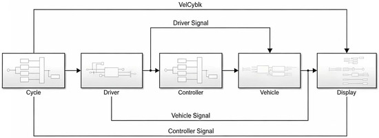
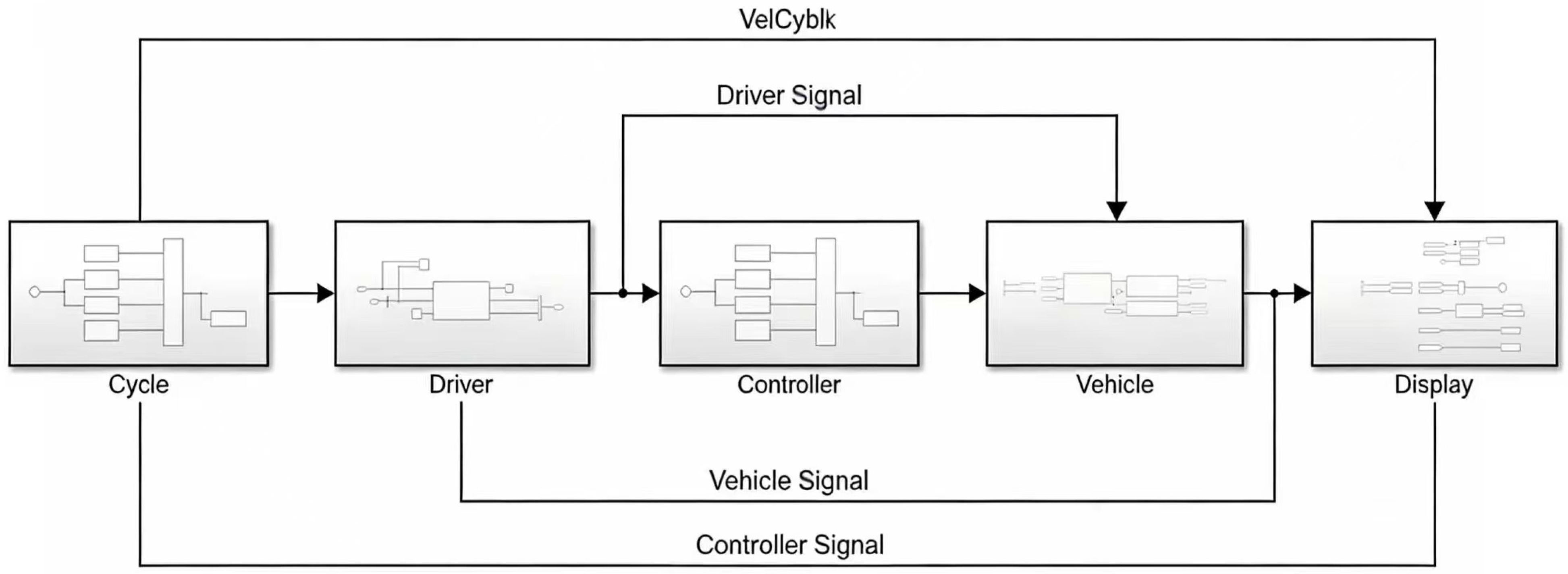
As illustrated in Figure 1, the system employs a forward-facing, closed-loop simulation architecture to address the dynamic control problem of vehicle trajectory tracking and energy distribution. The fundamental scientific problem modeled here is the continuous minimization of the error between the target reference speed (dictated by the CLTC cycle in the Cycle module) and the actual longitudinal vehicle speed.
Figure 1.
Basic function module.
In this data flow, the Driver module acts as a physiological-behavioral PI (Proportional-Integral) controller. It translates the speed tracking error into normalized accelerator or brake pedal commands (ranging from 0 to 1). These physiological signals are transmitted to the Controller module (acting as the Vehicle Control Unit, VCU), which calculates the precise optimal torque distribution based on the proposed dynamic series recovery strategy. This torque command is strictly bounded by scientific constraints: the real-time battery State of Charge (SOC) and the motor’s external characteristic limits. Finally, the Vehicle module executes these commands through multi-body longitudinal dynamics equations, feeding the resultant actual speed back to the Driver module to close the continuous control loop.
3.2. Core Modules
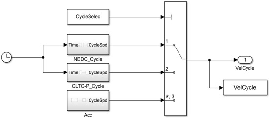
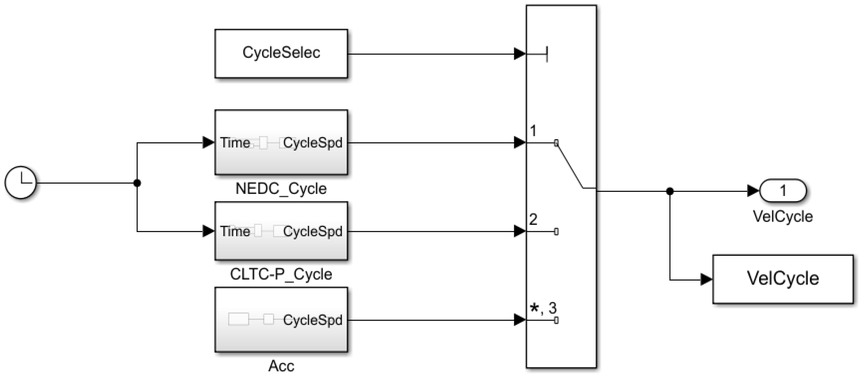
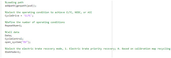
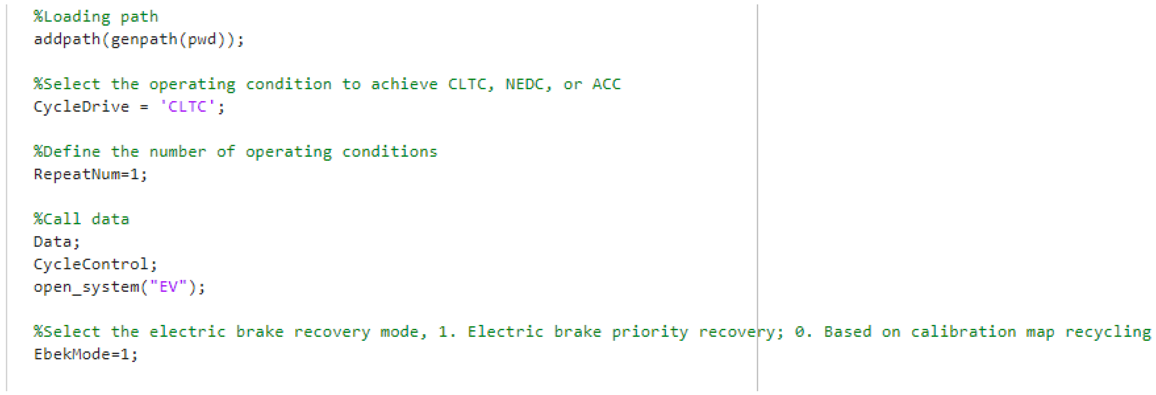
Cycle Module: The Cycle module (as shown in Figure 2) primarily manages the working condition control, and selects the working condition of simulation operation by defining the value of CycleSelec variable. The model calculates and defines the variables related to working conditions through the CycleControl script (as shown in Figure 3), and selects working conditions through the CycleDrive variable in the AutoRun script when the model is running.
Figure 2.
Cycle module.
Figure 3.
AutoRun Script Parameter Configuration Interface for Electric Vehicle Simulation Model.
Driver Module: The Driver module (shown in Figure 4) is implemented using the Longitudinal Driver block in the powertrain blockset toolbox, which outputs the opening of the accelerator pedal and the brake pedal.
Figure 4.
Drive module.
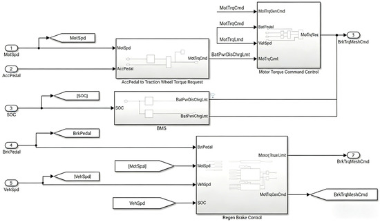
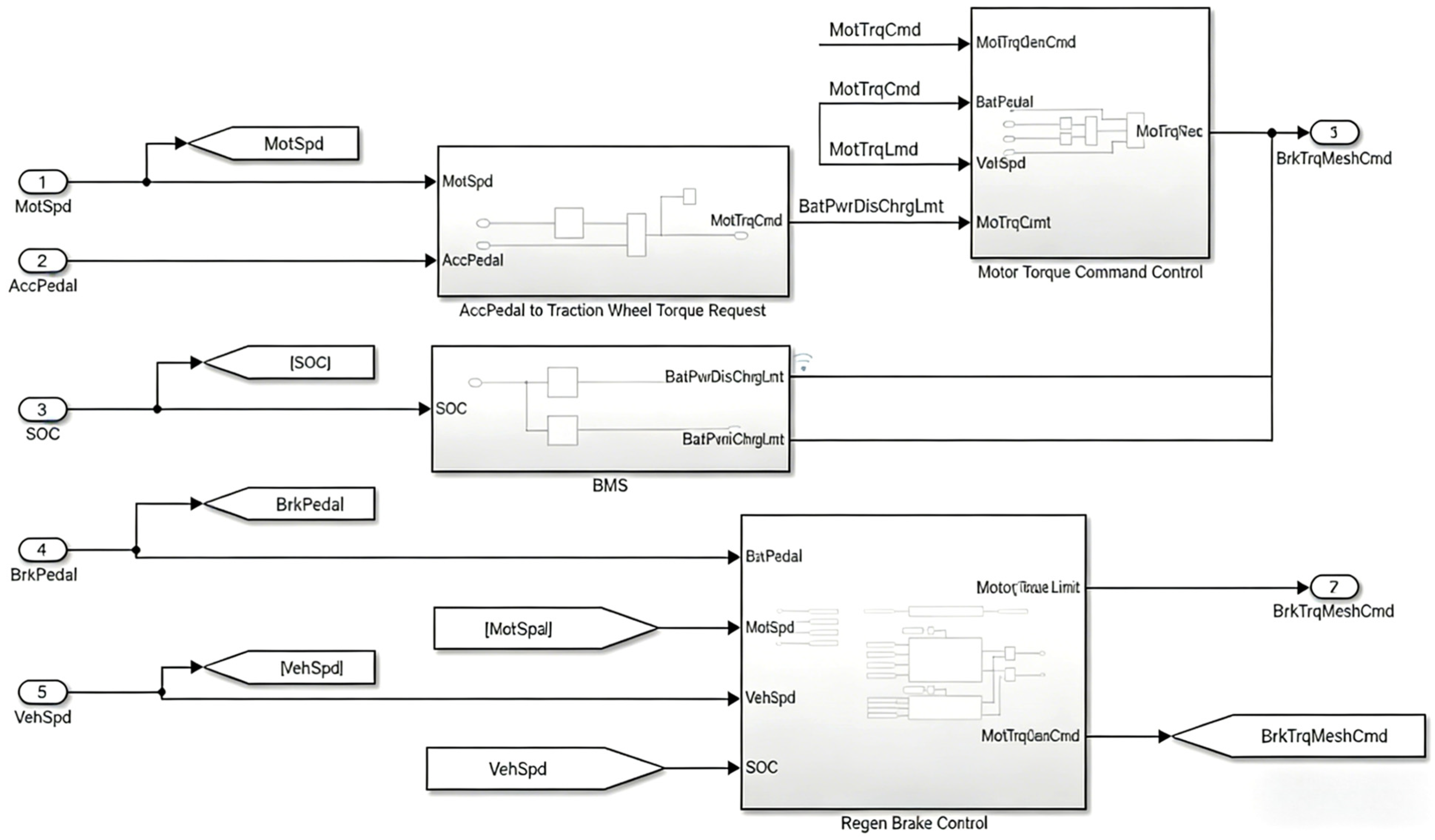
Controller Module: The controller module (structure shown in Figure 5) mainly completes the strategies of torque request calculation, BMS power limitation, motor torque control, motor torque limit, energy recovery and so on.
Figure 5.
Controller module.
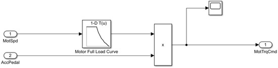
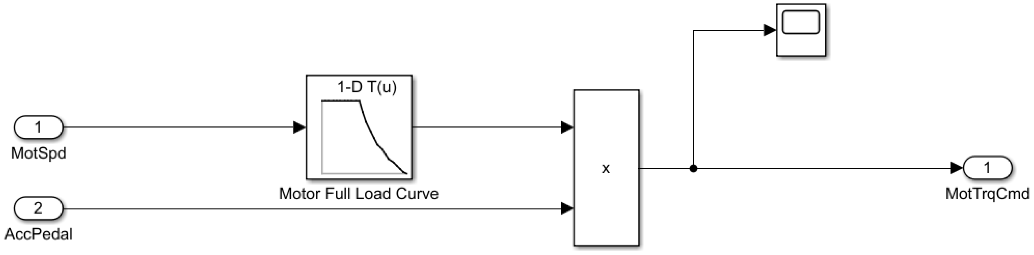
In this powertrain model (logic shown in Figure 6), the motor serves as the sole power output unit for the vehicle, where the accelerator pedal opening establishes a deterministic mapping relationship with the motor’s external characteristic curve. To simplify control logic and enhance response speed, the model employs a linearization approach, designing the pedal opening-motor output relationship as a linear proportional relationship (Equation (1)):
Figure 6.
Accpedal to traction wheel torque request module.
represents the motor drive torque output by the module; represents the opening degree of the accelerator pedal; represents the external characteristic torque of the motor.
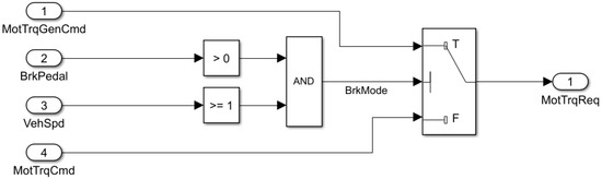
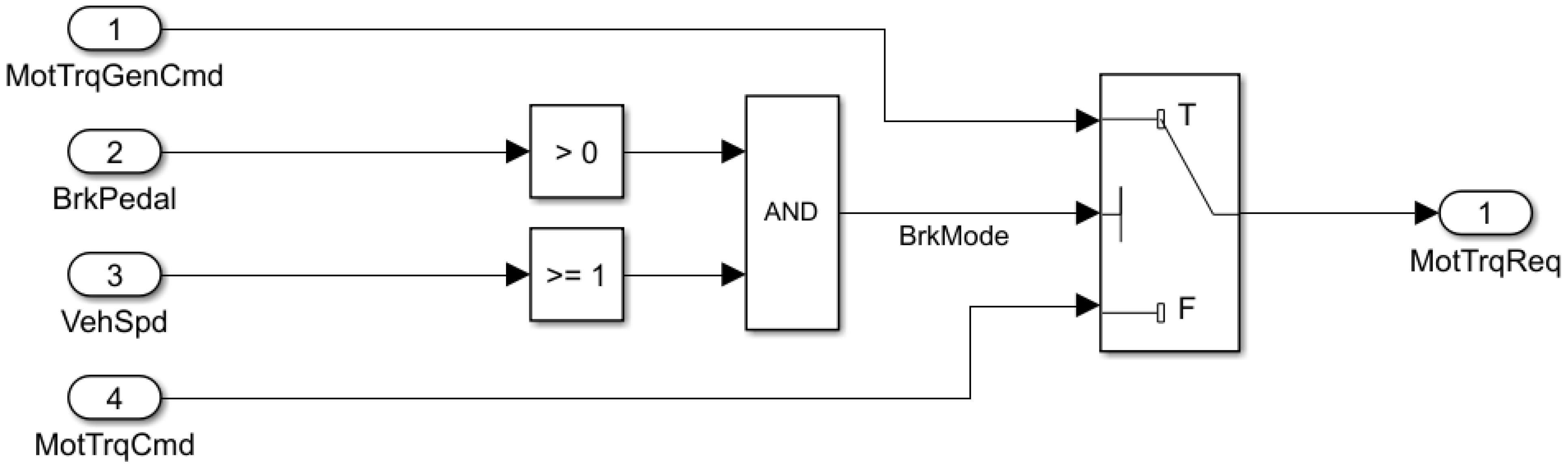
As illustrated in the Figure 7, the motor’s operating mode (driving/recovery) is determined by a logic judgment circuit: when the vehicle speed (VehSpd, Input 3) is not less than 1 km/h **and** the brake pedal opening (BrkPedal, Input 2) is greater than 0, the “AND” logic unit outputs a high-level signal (BrkMode = True). This signal triggers the selector module to switch to the energy recovery torque signal (MotTrqGenCmd, Input 1), which is then output as the motor torque request (MotTrqReq, Output 1)—indicating that the vehicle is in the braking state and the motor enters the regenerative energy recovery mode. Conversely, if either condition is not satisfied (i.e., vehicle speed < 1 km/h or brake pedal opening = 0), the “AND” unit outputs a low-level signal (BrkMode = False). The selector module will then select the driving torque signal (MotTrqCmd, Input 4) as the final motor torque request, and the motor will operate in the driving mode to provide traction power for the vehicle.
Figure 7.
Motor Torque Command Control module.
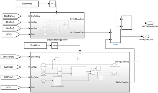
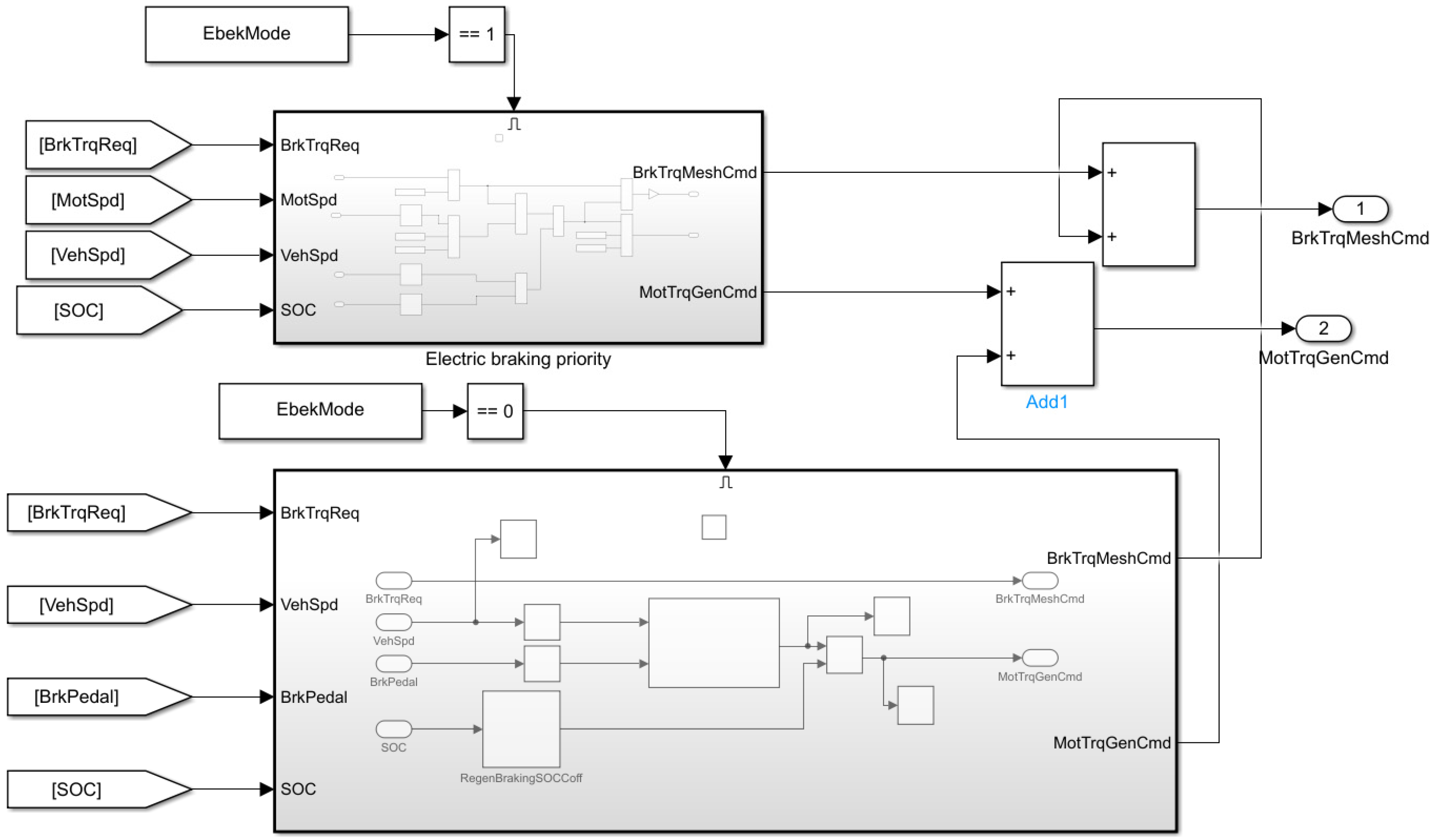
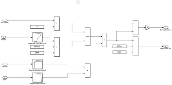
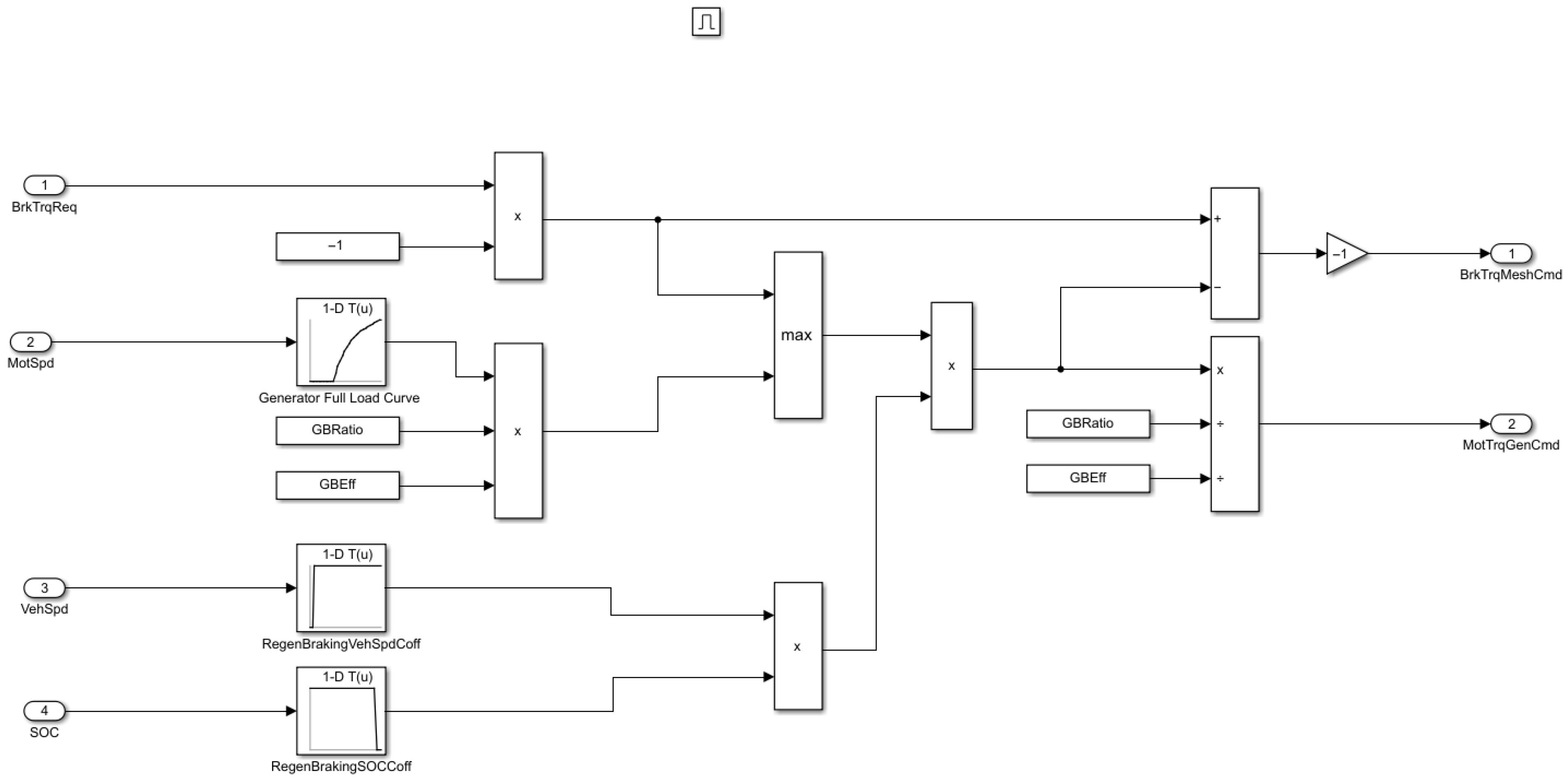
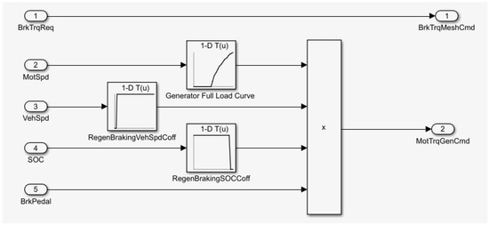
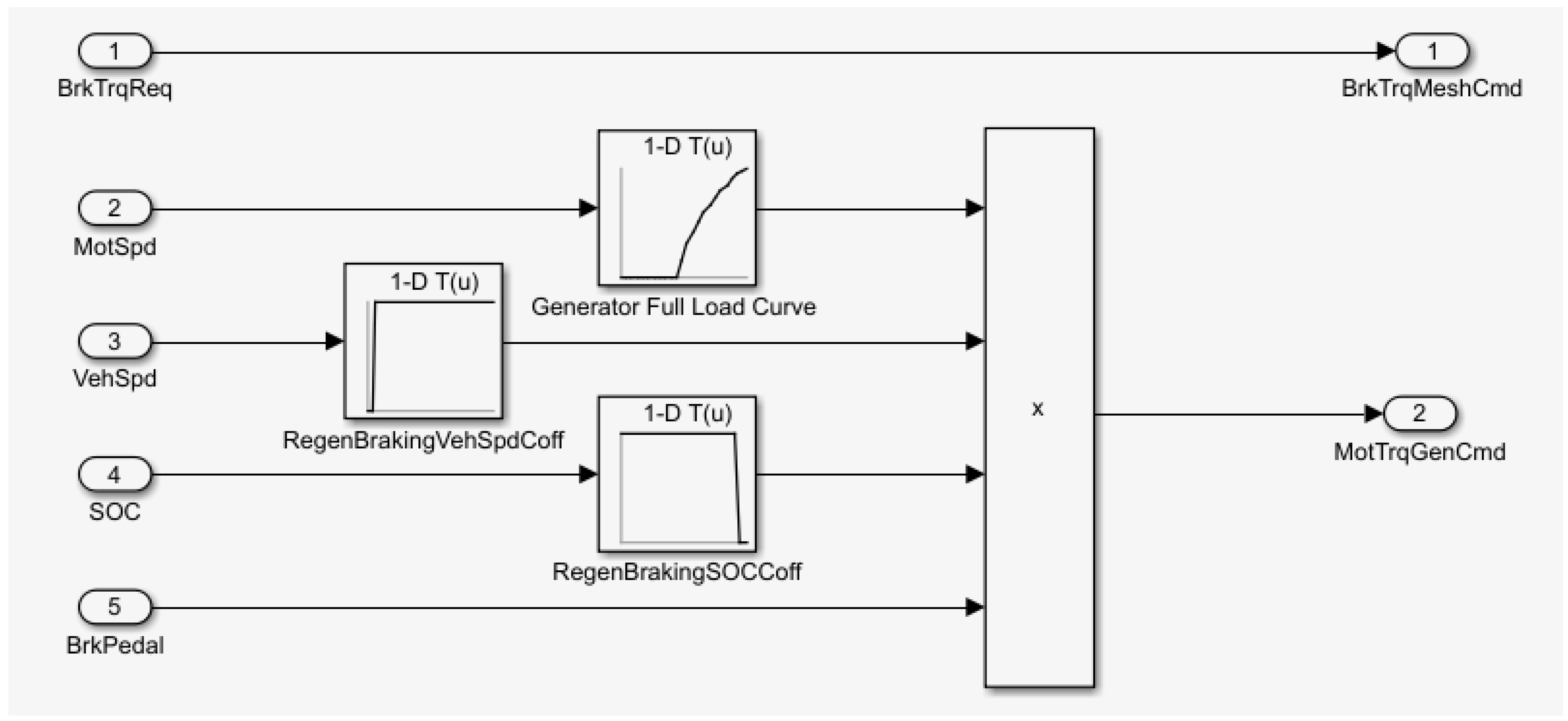
Braking energy recovery strategies primarily consist of two modes: series electric braking priority recovery and parallel electro-hydraulic collaborative recovery (as shown in Figure 8, Figure 9 and Figure 10). In the series recovery strategy with electric braking priority, the system dynamically allocates braking torque between front and rear axles based on braking intensity (Braking Intensity). When braking intensity is below 0.3, the entire braking force is borne by the front axle with a braking allocation coefficient of 1. For intensities between 0.3 and 0.7, the front axle allocation coefficient is adjusted to 0.85. When braking intensity exceeds 0.7, the front axle allocation coefficient is further reduced to 0.67 to prevent rear axle lockup. The system continuously compares the required braking force for the front axle with the maximum electric braking capacity of the motor. If the demand does not exceed the motor’s capability, the entire braking energy recovery is achieved by the drive motor. If the demand exceeds the capacity, the hydraulic braking system compensates to ensure the total braking force meets the driver’s intent. To balance battery safety and driving smoothness, the electric braking torque is dynamically adjusted according to vehicle speed and battery SOC. The system limits electric braking intensity in low-speed ranges to avoid jerking, while reducing or disabling energy recovery functions under high SOC conditions to prevent overcharging. These two strategies can be flexibly switched based on overall vehicle control requirements, balancing safety, energy efficiency, and driving comfort.
Figure 8.
Regen Brake Control module.
Figure 9.
Series recovery module.
Figure 10.
Parallel recovery module.
The initial calibration of the braking energy recovery control parameters in this strategy refers to the experience of existing strategy optimization research [21], and dynamically adjusts them based on the characteristics of front wheel drive vehicles, avoiding the problem of insufficient adaptability caused by fixed parameters in traditional strategies. At the same time, in the collaborative design of energy recovery and battery protection, the energy storage optimization idea of BLDC supercapacitor system was borrowed, which balanced the recovery efficiency and battery service life by limiting the recovery intensity under high SOC conditions; In the optimization of control logic, although complex intelligent algorithms [22] were not adopted, a simplified dynamic correction mechanism was used to achieve similar optimization effects while ensuring real-time responsiveness, which is more in line with engineering application requirements.
Vehicle Module: The Vehicle module integrates a motor, battery, and longitudinal dynamics module to convert commands into mechanical actions, with its core mathematical model as follows (Equation (2)):
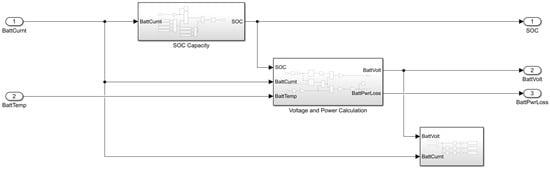
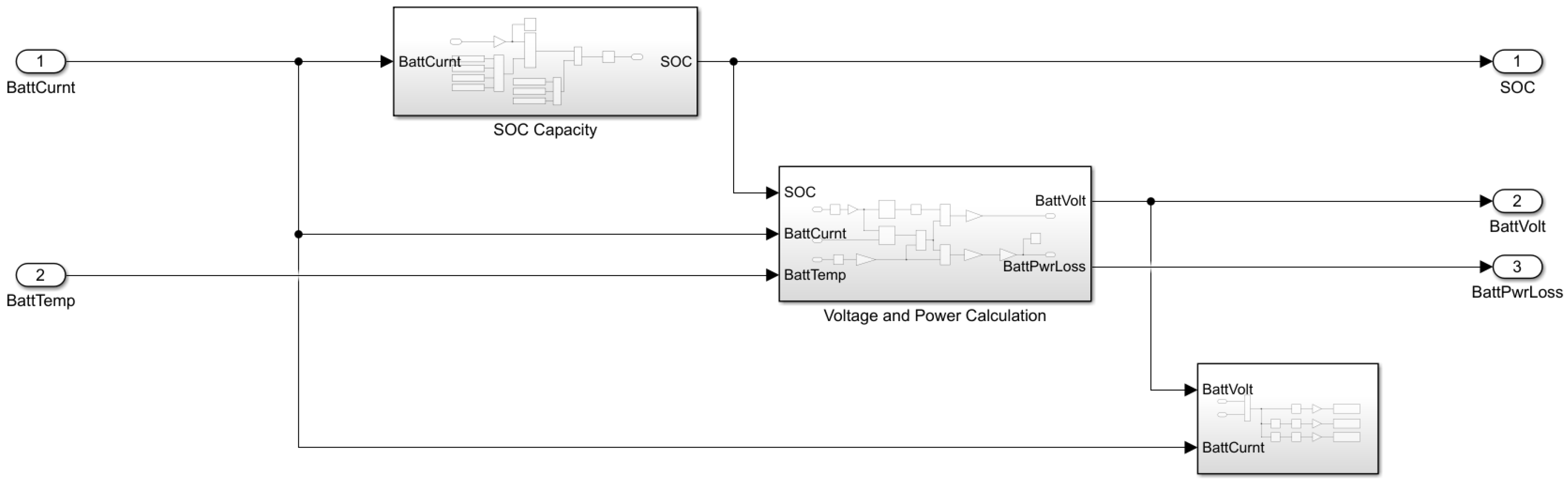
As the energy storage unit in EVs, the battery must be modeled (as shown in Figure 11) to account for its charge-discharge characteristics, temperature effects, aging factors, and SOC estimation.
Figure 11.
Battery module.
Among them, denotes the rated capacity of the battery, represents the current discharge current of the battery, and is the initial state of charge.
Motor model (as shown in Figure 12): The motor is responsible for converting electrical energy into mechanical energy. The model should include the motor’s electromagnetic characteristics, torque-speed relationship, thermal effects, and efficiency curve (Equation (3)).
Figure 12.
Motor module.
Among them, denotes the motor rotational speed, represents the motor torque, and refers to the current that the battery supplies to the motor.
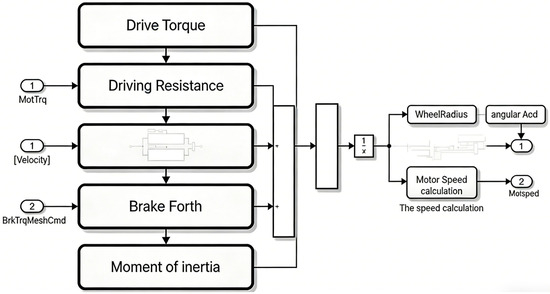
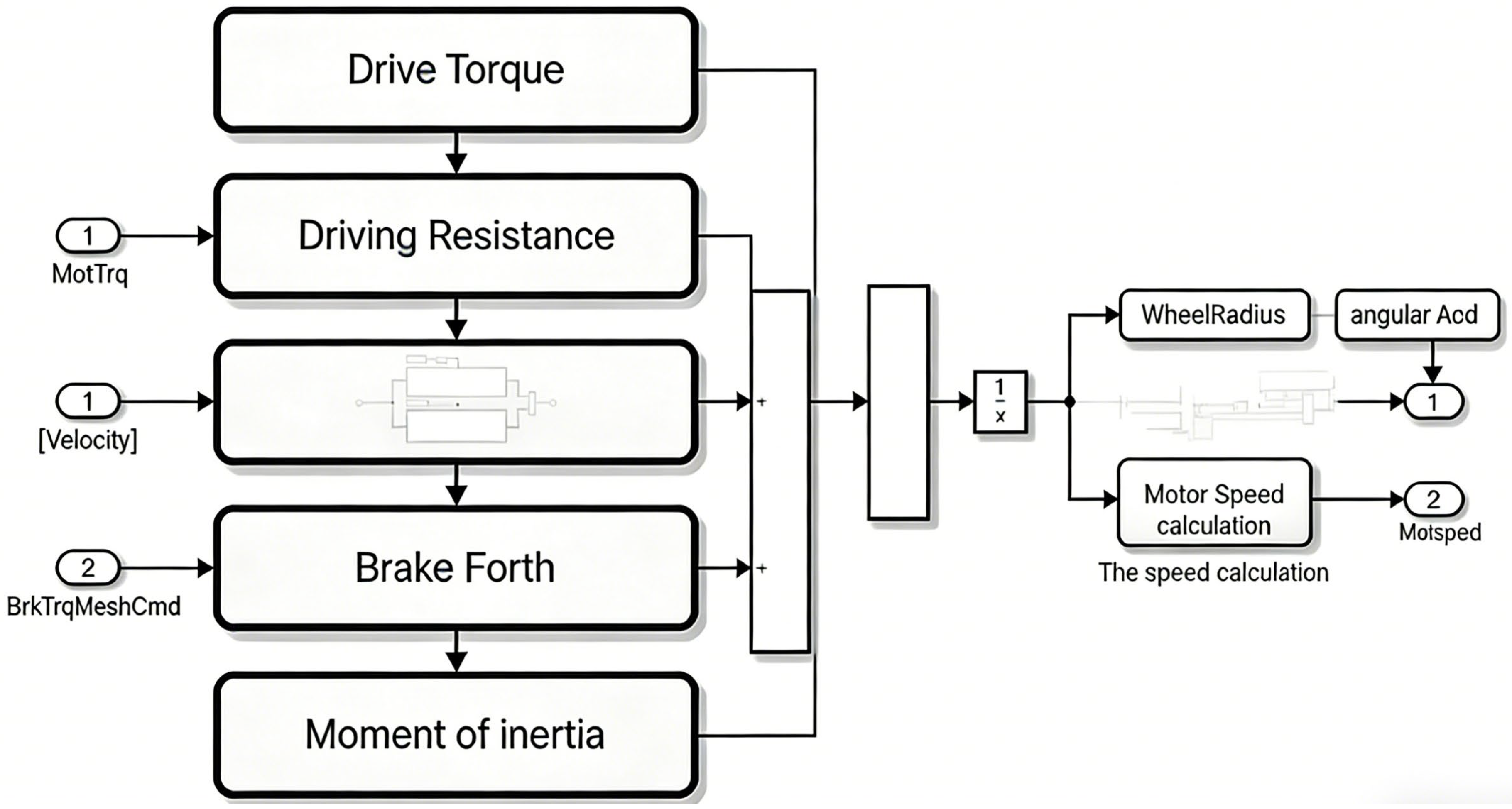
Vehicle dynamics model (as shown in Figure 13): The vehicle dynamics model includes the longitudinal, lateral and rotational motion equations of the vehicle, and the interaction between the tire and the ground. The specific components forces are defined in Equations (4)–(9).
Figure 13.
Vehicle longitudinal dynamics module.
Among them,
Among them, denotes the aerodynamic drag coefficient, A represents the frontal area, v is the relative velocity, refers to the road inclination angle, and stands for the vehicle’s climbing gradient; is the braking force, denotes the rolling resistance, represents the rolling resistance coefficient, and g is the gravitational acceleration (with a value of 9.8 m/s2); is the aerodynamic drag, denotes the grade resistance, and represents the acceleration resistance; meanwhile, is the driving torque, denotes the braking torque, and r stands for the wheel radius.
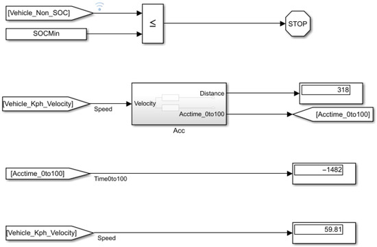
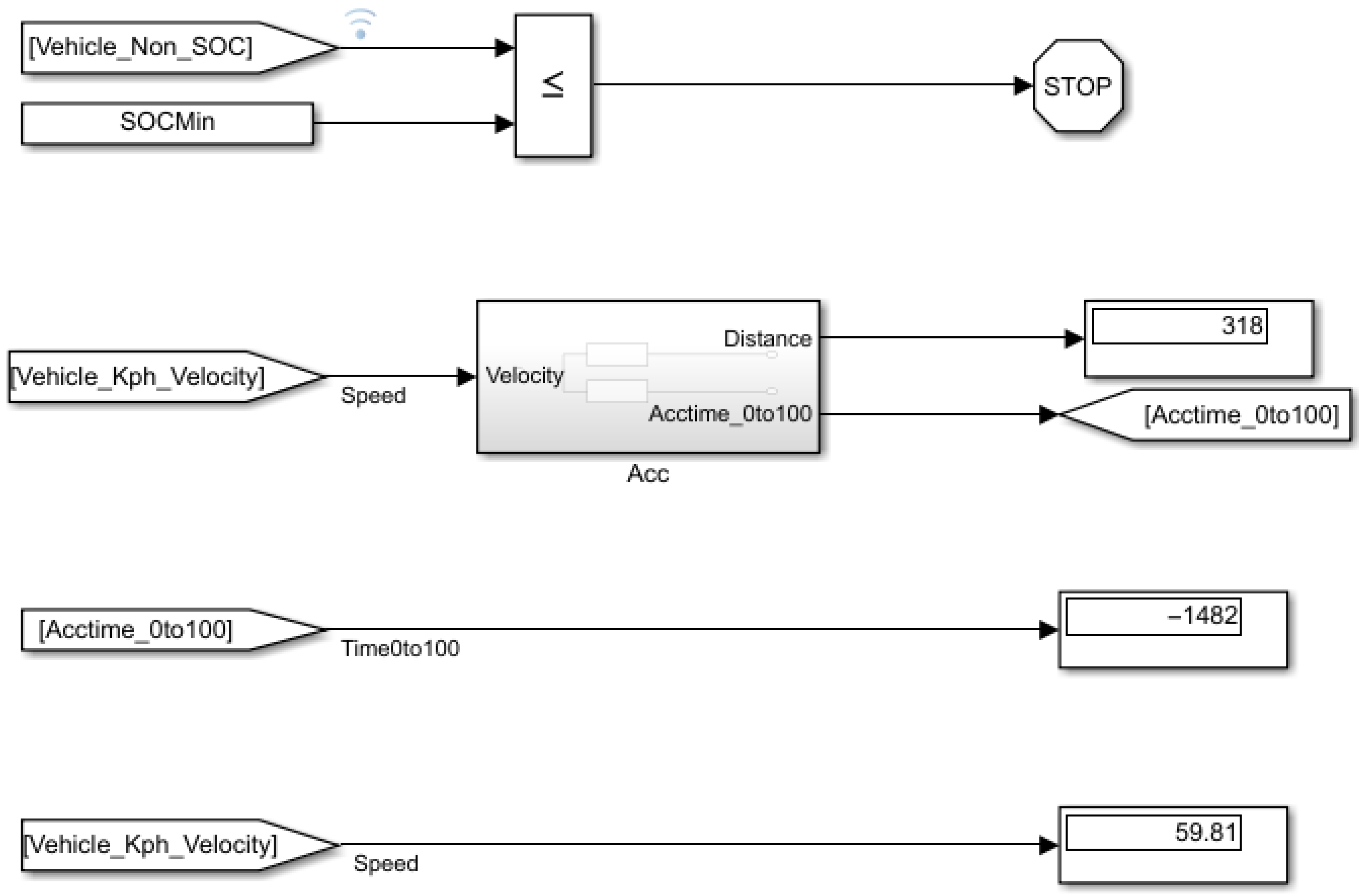
Display Module: When the SOC of the battery is less than the minimum allowable SOC of the battery, the simulation stops, and the cruising range can be viewed through display (as shown in Figure 14).
Figure 14.
Display module.
4. Results
The simulation results (as shown in Figure 15) for the parallel recovery mode indicate a total vehicle cruising range of 318 km.
Figure 15.
Cruising range in parallel recovery mode.
The simulation results (as shown in Figure 16) of series recovery mode are as follows: the cruising range of the whole vehicle is 400 km, and the cruising range is improved by 25.8%,which is superior to the improvement of existing composite braking energy recovery strategies [23] (about 19.2%) and the effect of a single drive motor recovery strategy [24] (about 17.6%). Compared with advanced systems using BLDC supercapacitor technology [25], although this strategy does not involve energy storage structure optimization, it achieves similar range improvement effects through innovative control logic, with lower complexity and easier engineering application. In addition, compared to optimization strategies based on intelligent algorithms [26], this strategy does not require a large amount of computing resources, and improves real-time responsiveness while ensuring recycling efficiency, which is more in line with the practical application scenarios of front wheel drive pure electric vehicles.
Figure 16.
Cruising range in series recovery mode.
5. Conclusions
Simulation comparisons under CLTC conditions show that the cruising range of the vehicle reaches 400 km under the dynamic series recovery strategy, which is 25.8% higher than the 318 km under the traditional parallel recovery strategy. This significant improvement benefits from two core innovations of the proposed strategy: first, the real-time adaptive adjustment of the front axle braking coefficient based on braking intensity—setting the coefficient to 1 when braking intensity is less than 0.3, adjusting it to 0.85 when braking intensity is between 0.3 and 0.7, and reducing it to 0.67 when braking intensity exceeds 0.7—effectively balancing braking stability and energy recovery efficiency while avoiding rear axle lockup; second, a dynamic correction mechanism integrates vehicle speed and battery state of charge (SOC) to limit electric braking intensity at low speeds to ensure driving smoothness and reduces or disables energy recovery under high SOC conditions to prevent battery overcharging, achieving a coordinated optimization of recovery efficiency, braking safety, and battery protection.
Compared with existing research results, the proposed strategy has obvious advantages in adaptability and comprehensiveness: it makes up for the lack of mainstream front-wheel-drive configuration adaptation in existing studies that focus on distributed drive or dual-motor structures, overcomes the defect of fixed braking force distribution ratio in traditional strategies, and solves the problem of insufficient consideration of multi-factor dynamic constraints such as vehicle speed and SOC in single-system-oriented recovery schemes. Meanwhile, the established Matlab/Simulink simulation framework realizes the modular integration of working condition control, driver simulation, controller strategy, vehicle dynamics, and result display, which can be reused for the development and verification of different braking energy recovery strategies, providing a low-cost and efficient test platform for the research and development of electric vehicle related technologies.
The research results not only provide direct technical guidance for the powertrain optimization of front-wheel-drive electric vehicles, helping to improve their energy utilization efficiency and cruising range, but also have practical significance for reducing the wear of the vehicle braking system, optimizing overall performance, and promoting the popularization and application of electric vehicles. In addition, the idea of dynamic allocation and multi-factor correction proposed in this study can also provide a reference for the optimization of braking energy recovery strategies for other types of electric vehicles [27] (such as distributed drive or hybrid power vehicles).
Author Contributions
Conceptualization, Y.H. and L.Y.; methodology, L.Y.; software, L.Y.; validation, L.Y. and Y.H.; formal analysis, L.Y.; investigation, L.Y.; resources, Y.H.; data curation, L.Y.; writing—original draft preparation, L.Y.; writing—review and editing, Y.H., L.D. and R.Z.; visualization, L.Y.; supervision, Y.H., L.D. and R.Z.; project administration, Y.H., L.D. and R.Z.; funding acquisition, Y.H. All authors have read and agreed to the published version of the manuscript.
Funding
This research received no external funding.
Data Availability Statement
Data is contained within the article. The original contributions presented in this study are included in the article. Further inquiries can be directed to the corresponding author.
Acknowledgments
Thanks to the North University of China for providing the necessary resources and support for this research. Special thanks go to my mentor and seniors who offered valuable suggestions and feedback throughout the project.
Conflicts of Interest
The authors declare that the research was conducted in the absence of any commercial or financial relationships that could be construed as a potential conflict of interest.
References
- Zhao, S.; Zheng, J.; Zhu, X.; Du, Z.; Wu, J.; Sun, B. Coordinated Control of Regenerative Braking and Vehicle Stability for PHHCV. In Proceedings of the 2019 IEEE 3rd Advanced Information Management, Communicates, Electronic and Automation Control Conference (IMCEC), Chongqing, China, 11–13 October 2019; pp. 269–274. [Google Scholar] [CrossRef] [Scilit]
- Xiao, B.; Lu, H.; Wang, H.; Ruan, J.; Zhang, N. Enhanced Regenerative Braking Strategies for Electric Vehicles: Dynamic Performance and Potential Analysis. Energies 2017, 10, 1875. [Google Scholar] [CrossRef] [Scilit]
- Qi, Z.; Yang, J.; Jia, R.; Wang, F. Investigating Real-World Energy Consumption of Electric Vehicles: A Case Study of Shanghai. Procedia Comput. Sci. 2018, 131, 367–376. [Google Scholar] [CrossRef] [Scilit]
- Tang, M.; Zhang, X. Optimal Regenerative Braking Control Strategy for Electric Vehicles Based on Braking Intention Recognition and Load Estimation. IEEE Trans. Veh. Technol. 2024, 73, 3378–3392. [Google Scholar] [CrossRef] [Scilit]
- Szumska, E.M. Regenerative Braking Systems in Electric Vehicles: A Comprehensive Review of Design, Control Strategies, and Efficiency Challenges. Energies 2025, 18, 2422. [Google Scholar] [CrossRef] [Scilit]
- Barcellona, S.; Barresi, M.; Noriega, H.; Scalabrin, R.; Baquero, R.S. Real Time Adaptive Energy Management Strategy for Electric Vehicles with Hybrid Energy Storage System. In Proceedings of the 2024 IEEE Vehicle Power and Propulsion Conference (VPPC), Washington, DC, USA, 7–10 October 2024; pp. 1–6. [Google Scholar] [CrossRef] [Scilit]
- Paredes, M.G.S.P.; Antenor Pomilio, J. Comparative Strategies of Control for Regenerative Braking in Electric Vehicles. In Proceedings of the 2019 IEEE 15th Brazilian Power Electronics Conference and 5th IEEE Southern Power Electronics Conference (COBEP/SPEC), Santos, Brazil, 1–4 December 2019; pp. 1–5. [Google Scholar] [CrossRef] [Scilit]
- Ai, Y.Y.; An, Y.H. Research on the Optimization Control Strategy of Brake Energy Recovery for Pure Electric Vehicles Based on Electro-Mechanical Brake System. Automot. Test Report. 2025, 139–141. [Google Scholar]
- Chen, D.L.; Tan, M.Y.; He, Z.Q.; Li, Z.F.; Mo, W.J. Hierarchical control strategy of regenerative braking energy recovery for distributed drive battery electric vehicles based on working condition recognition. Mach. Des. Res. 2025, 41, 244–249+254. [Google Scholar] [CrossRef]
- Cao, L.L.; Zhong, Y. Research on Drive and Regenerative Braking Control Strategy of Front and Rear Axle Dual-Motor Pure Electric Vehicles. Ph.D. Thesis, Fujian University of Technology, Fuzhou, China, 2025. [Google Scholar] [CrossRef]
- Peng, S.Y. Research on control strategy of EHB-motor composite braking system for electric vehicles oriented to energy recovery. Anhui Univ. Sci. Technol. 2025. [Google Scholar] [CrossRef]
- Lu, Y. Research on cooperative control strategy of electromechanical regenerative braking energy recovery system for battery electric vehicles. Automot. Test Rep. 2025, 145–147. [Google Scholar]
- Li, J.; Xu, H.; Wang, J. Regenerative Braking: An Overview of Technologies and Applications. Electr. Power Syst. Res. 2024, 188, 106274. [Google Scholar]
- Qiu, C.; Li, F.; Liu, J. A Novel Control Strategy of Regenerative Braking System for EVs Under Safety-critical Driving Conditions. Energy 2018, 145, 340–348. [Google Scholar]
- Zhou, X.; Chen, L. Research on Regenerative Braking Systems: A Review. Energy Rep. 2025, 6, 302–315. [Google Scholar]
- Xie, Q.; Zhao, Y. Optimization of Regenerative Braking Using Q-Learning for Electric Vehicles. IEEE Trans. Control. Syst. Technol. 2024, 32, 2081–2089. [Google Scholar]
- Kumar, P.; Sharma, S. Energy Consumption Characteristics with Regenerative Braking for Electric Vehicles. Energy Rep. 2023, 8, 760–768. [Google Scholar] [CrossRef] [Scilit]
- Chidambaram, R. Effect of Regenerative Braking on Battery Life and Efficiency. Energies 2023, 16, 5303. [Google Scholar]
- Wang, Q.; Li, Y.; Yu, X. Regenerative Braking Control Based on Hybrid Optimization Algorithms. Appl. Energy 2025, 322, 118420. [Google Scholar]
- Hannan, N.; Shib, K.S.; Shufian, A.; Islam, M.A.; Sharan, S.M.I.; Gupta, A.D. Advanced regenerative braking system for EVs: Leveraging BLDC-supercapacitor technologies for optimized energy recovery, economic viability, and maintenance strategies. Future Batter. 2025, 7, 100103. [Google Scholar] [CrossRef] [Scilit]
- Xiao, L.W. Optimization research on regenerative braking energy recovery control strategy for battery electric vehicles. Agric. Equip. Veh. Eng. 2025, 63, 74–78. [Google Scholar]
- Sinha, D.; Majumder, S.; Bandyopadhyay, C.; Sharma, H.K. Arithmetic Harris Hawks-Based Effective Battery Charging from Variable Sources and Energy Recovery Through Regenerative Braking in Electric Vehicles, Implying Fractional Order PID Controller. Fractal Fract. 2025, 9, 525. [Google Scholar] [CrossRef] [Scilit]
- Zhu, Y.D.; Li, J.; Li, W.M.; Liu, X.B.; Li, Y.J. Research on control strategy of electro-hydraulic composite braking energy recovery for electric vehicles. J. Lanzhou Inst. Technol. 2025, 32, 84–87+106. [Google Scholar]
- Peng, K. Efficiency optimization and maintenance strategy of braking energy recovery system for pure electric vehicles. Automot. Maint. Tech. 2025, 15–16. [Google Scholar]
- Zhang, Z. Research on Control Strategy of Regenerative Braking Energy Recovery for Electric Vehicle Drive Motor. Ph.D. Thesis, Chongqing University of Technology, Chongqing, China, 2025. [Google Scholar] [CrossRef]
- Qin, Y.N. Research on Optimal Control Strategy of Composite Braking Energy Recovery for Battery Electric Vehicles. Ph.D. Thesis, Yancheng Institute of Technology, Yancheng, China, 2025. [Google Scholar] [CrossRef]
- Wu, X.H. Research and Implementation of Electric Vehicle Braking Energy Recovery System Based on Computer. J. Phys. Conf. Ser. 2021, 1744, 022080. [Google Scholar] [CrossRef] [Scilit]









Disclaimer/Publisher’s Note: The statements, opinions and data contained in all publications are solely those of the individual author(s) and contributor(s) and not of MDPI and/or the editor(s). MDPI and/or the editor(s) disclaim responsibility for any injury to people or property resulting from any ideas, methods, instructions or products referred to in the content. |
© 2026 by the authors. Licensee MDPI, Basel, Switzerland. This article is an open access article distributed under the terms and conditions of the Creative Commons Attribution (CC BY) license.