


Abstract
Feed handling activities in cattle feedlots—such as feed leveling, reconditioning, and the removal of feed refusals along the trough—remain largely manual in many developing countries, resulting in high labor demand and inconsistent feed availability. This study aimed to design, develop, and evaluate an integrated machine capable of leveling feed, conditioning refused feed, and collecting feed refusals. The machine was developed using trough-geometry data (550–650 mm) and feed-residue properties (particle size, bulk density, terminal velocity), integrating a shovel–dual-brush unit with pneumatic suction. A prototype was subsequently fabricated and tested under practical feedlot conditions using various trough widths and operating speeds. Performance evaluation included feed-pile geometry, distribution uniformity, suction efficiency, suction capacity, and fuel consumption. The leveling mechanism significantly improved feed distribution uniformity, reducing the coefficient of variation for feed-pile height and feed mass by up to 67% and 73%, respectively. During conditioning, the machine increased feed-pile height by 8–10 cm and reduced pile width by 6–13 cm. The suction system maintained high efficiency (94–97%) with an average capacity of 14.1 ± 0.8 kg·min−1. Fuel consumption ranged from 0.54 L·h−1 during leveling to 1.30 L·h−1 during suction. Overall, the machine offers a practical solution for improving feed shaping, uniformity, and residue removal.
1. Introduction
Demand for beef in developing countries continues to increase due to population growth, urbanization, rising household incomes, and shifts in dietary preferences. Indonesia, the world’s fourth most populous country, had an estimated 287.6 million people in 2025, yet per capita beef consumption remains low at 2.25–2.91 kg per year [1]. Although the national cattle population reached approximately 11.75 million head in 2024, domestic production has not fully met national beef demand, resulting in continued reliance on imports. At the same time, the sector’s growth has been driven by several market dynamics, including the expansion of domestic commercial feedlot enterprises, increasing numbers of imported feeder cattle for fattening, and rising consumer demand associated with urban population growth; collectively, these factors contribute to the observed sectoral expansion [1]. Recent data indicate that Indonesia’s feedlot sector has continued to grow, with more than 200 thousand head of cattle handled annually in feedlot operations, including the intake of feeder cattle and the turnover of finished cattle prepared for slaughter. Most feeder cattle are imported from Australia at entry weights of 280–350 kg live weight. Under these systems, cattle typically achieve an average daily weight gain (ADG) of 1.5–2.0 kg·day−1, which aligns with performance commonly observed in Indonesian commercial feedlot operations finishing Brahman-cross feeder cattle [2]. To reduce feeding costs, Indonesian feedlots rely extensively on agricultural and agro-industrial by-products such as rice straw, sugarcane tops, rice husks, soybean hulls, corn stalks, palm-kernel cake, rice bran, molasses, tapioca waste, and pineapple waste [3], which are generally high in fiber and low in crude protein, with only a few exceeding 20% CP [4]. Properly formulated complete feeds based on local ingredients can improve animal performance when nutritional requirements are met [5]. However, their fibrous and moist nature makes them susceptible to compaction—due to moisture retention and prolonged mechanical pressure—and to segregation during transport or loading, when particles of different sizes and densities separate. Both forms of physical deterioration can reduce feed uniformity and accessibility, ultimately affecting animal intake if not properly managed [6]. As feeding operations strongly influence production efficiency and cost structure in integrated livestock systems, these challenges highlight the need for practical, locally adaptable feeding technologies [7].
In response to labor constraints and efficiency demands, automated cattle feeding systems have increasingly been adopted in intensive livestock operations [8]. Such systems have been reported to influence feed alley design and daily farm management practices by improving feed accessibility and the consistency of feed distribution [9]. Several automatic feeding machines have been developed to mechanize feed delivery and reduce labor requirements [10]. Nevertheless, in many cattle feeding facilities—particularly in developing countries—feeding infrastructure remains dominated by fixed concrete feed troughs, and critical tasks such as feed reconditioning, leveling, and removal of refused feed are still performed manually. This mismatch between available automation technologies and prevailing on-farm practices highlights the need for integrated feeding machines that can operate effectively within existing trough configurations.
Most commercial feedlots in Indonesia employ open concrete feed troughs with concave bottoms. Based on onsite measurements at several commercial feedlots in East Java and Lampung provinces, these troughs generally have an inner width of 55–65 cm and a depth of 40–45 cm. Feed is commonly delivered two or more times per day in the form of mixed rations containing moist or fibrous materials. As feeding progresses, cattle tend to avoid consuming feed remaining at the bottom of the trough, particularly when it becomes compacted or partially decomposed. Diets containing fibrous roughage sources can exacerbate feed compaction and uneven distribution, emphasizing the need for effective feed reconditioning and leveling mechanisms [11]. Consequently, remaining feed must be manually turned and piled toward the center of the trough using simple tools, such as shovels, to restore feed accessibility. Although automatic feeding systems with dynamic feed delivery have been shown to improve feed accessibility and feeding behavior [12], these systems are rarely applicable in feedlots with fixed concrete troughs, where manual feed turning and redistribution remain necessary. Locally designed livestock feed machinery has been shown to reduce labor requirements and improve operational efficiency when tailored to specific on-farm conditions [13].
In addition to feed reconditioning, uneven feed distribution along the trough length frequently occurs due to variations in feed delivery patterns and animal feeding behavior. Such unevenness leads to feed accumulation in certain sections and shortages in others, increasing competition among animals and resulting in unequal feed intake and growth performance [14]. Manual feed leveling is therefore required, further increasing labor demand. Feed refusals—defined as the portion of total mixed ration remaining in the trough before the next feeding—represent another persistent challenge. These refusals must be removed prior to subsequent feeding, as mixing them with fresh feed can reduce feed quality, increase spoilage, and negatively affect animal intake [15,16]. In Indonesian feedlots, refusal removal is typically conducted manually, requiring significant labor input and raising concerns related to hygiene, worker safety, and operational efficiency. Feed losses and refusals at the trough level have been shown to significantly reduce feeding efficiency and complicate accurate assessment of livestock productivity [17].
Although various feeding machines—such as feed mixers—have been developed to improve feed preparation efficiency using locally available materials [18], most existing equipment is designed primarily for feed preparation rather than in-trough feed management. As a result, essential tasks such as feed reconditioning, leveling, and refused-feed collection remain predominantly manual, and no integrated machine is currently available to perform these functions simultaneously within the feed trough. Existing mechanized equipment generally addresses only a single operation and is rarely engineered for in-trough use under the spatial and structural constraints of Indonesian feedlots, where fixed concrete troughs typically measure only 55–65 cm in inner width, feature concave bottoms, and offer limited working space. Meanwhile, automated and mechanized feeding technologies widely used in intensive cattle systems worldwide—including robotic feed pushers, belt-type feeding systems, automatic feed mixers, and vacuum-based residue collectors—are designed for wide, open feeding alleys or standardized trough geometries, making them incompatible with Indonesia’s narrow and fixed trough configurations. Moreover, these systems lack multifunctional capability: they cannot simultaneously recondition compacted feed, level uneven piles, and collect refusals within confined trough interiors. This clear mismatch between available technologies and local infrastructure highlights a significant technological gap and underscores the need for a compact, multifunctional, affordable, and locally adaptable machine aligned with future feed-technology directions emphasizing efficiency and sustainability [19].
In this study, we highlight four key innovations of the proposed machine: it (1) integrates feed turning, leveling, and pneumatic residue collection into a single unit; (2) employs a brush–shovel assembly tailored for confined concrete troughs; (3) uses a suction subsystem adapted for moist, fibrous feed residues; and (4) applies parameter-based modeling to determine essential geometric and operating parameters.
Therefore, the objective of this study was to design and develop an integrated feed-conditioning machine designed to handle feed within cattle feed troughs, capable of (i) leveling feed piles, (ii) turning and reconditioning feed, and (iii) collecting feed refusals. A prototype machine was fabricated and experimentally evaluated to assess its functional and mechanical performance under practical feedlot operating conditions.
2. Materials and Methods
2.1. Measurement of Feed Trough Dimension and Feed Characteristics
To design the head section of the machine that operates inside the feed trough, accurate geometric data of the trough are required. Identification of the trough shape and dimensions was carried out at a commercial feedlot facility owned by one of the largest livestock companies in Indonesia, located in Lampung Province, where the developed machine was tested. This feedlot has 20 pens and uses a mechanized Total Mixed Ration system, with the feed mixed and delivered directly to the feed troughs by TMR feed trucks.
The measured geometric parameters included the height of the outer front wall from the road surface (Ho), front wall thickness (Tw), inner front wall height (Hi), inner width (Wi), and trough depth (Hb) (Figure 1). All measurements were carried out using a ruler with an accuracy of 1 mm. Preliminary observations revealed that multiple trough configurations were used at the feedlot; therefore, measurements were performed on all existing trough types to capture this variability. In total, four types of troughs were identified. For each type, two trough units were measured, and each dimensional measurement was repeated five times. In addition, the concavity of the trough bottom was measured using a relief meter with a pin spacing of 5 cm and an accuracy of 1 mm.
Figure 1.
Geometric parameters measured on the feed trough.
To determine the appropriate dimensions and operating mechanism of the feed turning system, data on the physical characteristics of the feed are required. Similarly, the design of the pneumatic suction system for collecting residual feed necessitates information on the terminal velocity of the feed fractions.
The physical characteristics of cattle feed evaluated in this study included: (1) feed fraction composition based on form (leaves, stems, and granules) and granule size; (2) bulk density; (3) moisture content; and (4) terminal velocity. The classification of feed fractions was adapted from [20] and modified to reflect the actual conditions of feed used in the feedlot. Feed samples were collected from refused feed remaining in the feed trough.
The collected feed was manually sorted according to its form and separated for subsequent measurements (Figure 2). The granular fraction was further classified using sieves with 5 mm and 7 mm openings. Based on particle size, granules were grouped into three categories: large granules (>7 mm), medium granules (5–7 mm), and small granules (<5 mm).
Figure 2.
Classification and separation of cattle feed fractions for physical property measurements: (a) leaf fraction, (b) stem fraction, (c) granules.
Bulk density of each feed fraction was determined by filling a 1000 mL graduated cylinder with the sample and weighing it using a digital scale (CHQ, Dongguan, China) with an accuracy of 0.01 g. Each measurement was conducted in three replications. Feed moisture content was measured using the gravimetric oven-drying method at 105 °C for 24 h, with five samples analyzed for each feed fraction.
The terminal velocities of the feed fractions were measured using a vertical wind column apparatus (Pudak Scientific, Bandung, Indonesia), following the procedure outlined by [18]. In this method, upward airflow was gradually increased until the particles reached suspension, thereby allowing the determination of their terminal velocities. This technique is widely applied to assess the aerodynamic properties of agricultural granular materials [21]. For each feed fraction, 50 samples were randomly selected, each weighed with a digital scale (accuracy 0.01 g) and measured using a digital caliper (accuracy 0.01 mm). Specifically, for the leaf fraction, length and width were recorded; for the stem fraction, length and diameter were measured; and for the granule fraction, particle diameter was determined. From the collected samples, the ten heaviest specimens in each feed fraction were selected, as higher mass is associated with larger and more compacted particle aggregates that require greater airflow to be entrained. These samples therefore represent the most severe conditions for terminal-velocity measurement and the most critical scenario for pneumatic conveying design. The maximum terminal velocity obtained was then used as the design reference for determining the minimum required suction air velocity of the feed collection pneumatic system.
2.2. Machine Design Concept
The integrated machine was conceptually designed to perform three essential in-trough operations—feed turning and conditioning, feed leveling, and refused-feed collection—within the concrete troughs commonly used in Indonesian feedlots. Its configuration (Figure 3) was guided by the geometric constraints of existing troughs and the physical characteristics of the feed material, requiring reliable operation in troughs 550–650 mm wide with varied bottom profiles while accommodating the maximum observed leaf and stem dimensions to avoid wall contact. The leveling and turning mechanisms were engineered to handle fibrous feed materials such as corn and Napier grass, with particle lengths up to 400 mm and bulk densities of 0.10–0.30 g·cm−3, whereas the suction system was sized to recover refused feed based on particle terminal velocities of approximately 8–10 m·s−1 to prevent clogging and ensure stable pneumatic transport. Overall, the design emphasized compatibility with trough geometry, adaptability to feed physical properties, compact integration of multiple functions, and safe, straightforward operation under practical on-farm conditions.
Figure 3.
Configuration of the main components of the integrated feed-handling machine: (1) shovel; (2) rotating brushes; (3) rake; (4) blower; (5) feed-collection sack; (6) head unit; (7) brush motors; (8) slider mechanism; (9) AC generator set; (10) cyclone separator; (11) three-wheeled mini truck.
Feed turning and conditioning were accomplished using a shovel combined with dual rotating brushes. The use of a rotating brush system to draw in and collect scattered materials has been proven effective in gathering substances such as cattle feed [22,23]. The shovel (1) acted as the primary lifting and guiding element, elevating compacted feed from the trough bottom, while the rotating brushes (2) promoted feed loosening, flipping, and controlled rearward redistribution. This interaction enabled effective feed reconditioning while reforming the material into a centralized and accessible pile.
Feed leveling was integrated into the same shovel–brush assembly through the addition of a rake (3) positioned above the feed pile. The rake suppressed excessive feed height and prevented localized over-piling, while the shovel lifted feed from the trough base and the rotating brushes redistributed it along the trough length. This coordinated mechanism improved feed uniformity without the need for separate leveling devices.
Collection of feed refusals was carried out using a pneumatic suction system powered by a centrifugal blower (4). This type of system is well-suited for handling granular and fibrous materials such as feed [24]. The concept was selected because feed residues accumulate at the bottom of the trough and must be directly transported into a collection sack (5) mounted on the machine. The suction intake head (6) was designed for insertion into the trough and for both vertical and lateral repositioning during operation to ensure complete removal of residual feed. To enhance performance, a rotating brush system (7) was integrated to loosen compacted feed and direct scattered particles toward the suction inlet. This dual mechanism ensures that both fine particles and larger feed fragments are efficiently conveyed into the collection sack. Compared with mechanical conveying systems, the brush–vacuum approach offers greater flexibility, reduced mechanical complexity, and improved adaptability to confined trough geometries under practical feedlot conditions. By contrast, Vásquez Llave et al. [25] employed a combination of inclined belt conveyor and vacuum for highway trash collection, which is suitable for spacious environments. In feedlot applications, however, the brush–vacuum system provides a more precise and efficient solution for localized residues within narrow troughs.
The rotating brush unit was driven by a pair of AC electric motors (7), while the positioning of the shovel–brush assembly was achieved using a sliding frame mechanism (8) actuated by a chain-driven screw. The left–right and vertical (up–down) movements of the sliding frame were independently controlled by dedicated AC electric drive motors. Electrical power for all electric motors was supplied by an onboard AC generator (9). The blower of the pneumatic suction system was driven independently by a gasoline engine (Honda, Bangkok, Thailand), and a cyclone separator (10) was employed to separate feed particles from the airflow prior to collection in feed-collection sack.
All components were mounted on a commercially available three-wheeled mini truck (11), which served as the prime mover. This platform was selected due to its wide availability on the local market, relatively low cost, adequate payload capacity, and sufficient cargo-bed space for accommodating the integrated system components. In addition, its compact dimensions and tight turning radius provide high maneuverability along narrow feed alleys and between opposing feed troughs under confined feedlot conditions commonly encountered in Indonesia. The mini truck was powered by an engine rated at 7.5 kW at 7500 rpm, which was sufficient to support machine mobility and auxiliary system operation.
The operational concept of the machine, in which it travels along the feed alley adjacent to the feed trough during feed-handling activities, is illustrated in Figure 4.
Figure 4.
Conceptual operation of the integrated feed handling machine along the feed trough.
2.3. Head Unit of Feed Collecting and Turning System
The head unit operates directly inside the feed trough and is designed to perform three main functions: leveling uneven feed piles, conditioning and turning uneaten feed, and collecting feed residues for suction. To carry out these functions under varying trough geometries and feed conditions, the head unit integrates a rake, a shovel assembly, and a counter-rotating dual-brush assembly.
To analyze the flow of material within the brush–shovel mechanism, a schematic is developed to illustrate the mass velocity and the cross-sectional areas traversed as the shovel moves forward and the brushes rotate to draw the material, push it onto the shovel surface, and discharge it through the rear opening to form a pile behind the machine, as shown in Figure 5. Furthermore, an additional schematic diagram was prepared to illustrate the relationship between the feed-material velocity at the rear opening and the desired pile height, as shown in Figure 6.
Figure 5.
Schematic diagram of volumetric feed flow in head unit with shovel and brush mechanism.
Figure 6.
Schematic diagram of feed flow velocity at the rear opening to achieve the target rear pile height.
By referring to Figure 6, the required initial ejection velocity at the rear opening (the back end of the shovel) can be analyzed to ensure that material from the lower layer can be projected upward onto the intended pile. Using the kinematics of uniformly accelerated motion, the initial ejection velocity required to reach the target conditioned pile height can be expressed as:
where is the ejection velocity (m·s−1), is the maximum projection height measured from the rear end of the shovel (m), is the shovel inclination angle (°), is the target pile height (m), is the height of the rear end of the shovel (m), and is the shovel length (m).
The motion at the end of the shovel is generated by the pushing action of the brush; therefore, its velocity originates from the linear velocity of the lower brush-wire tips. Since a reduction in velocity occurs from the lower point of the shovel to its upper end due to the height gain , the required initial velocity at the lower point must be greater than . Assuming no friction for simplification, the relationship becomes:
When the brush is mounted at an incline matching the shovel plane, corresponds to the linear velocity of the lower brush-wire tips. In this concept, the lower layer of feed is projected upward, while the upper layer is simply passed through to the rear opening and allowed to fall onto the trough bottom, resulting in the feed being flipped as it moves. Accordingly, the required brush rotational speed can be determined as:
where is the rotational speed of the brush (rpm), and is the radius of the lower brush circle (m).
To maintain smooth feed flow from the feed trough through the brush segment to the rear opening, the flow rates must satisfy:
where is the volumetric intake flow rate (m3·s−1), is the volumetric flow rate in the KLMN section (m3·s−1), and is the volumetric flow rate at the rear opening (m3·s−1).
The volumetric feed-intake flow rate is given by the cross-sectional area of the feed pile (ABCD plane) multiplied by the forward velocity of the shovel:
where is the area of the ABCD segment (m2), is the forward velocity of the shovel (m·s−1), is the shovel width (or feed-trough width) (m), and is the feed pile height (m).
The feed then enters the region between the two brushes (KLMN), with volumetric flow rate:
where is the area of the KLMN segment (between the two brushes) (m2). The area of the KLMN section can be calculated as follows:
where is the distance between the lower brush tips (m), is the distance between the upper brush tips (m), is the brush height (m), is the brush shaft spacing (distance between left and right brush shafts) (m), is the radius of the upper brush circle (m), and is the radius of the lower brush circle (m).
The average pulling velocity on the KLMN plane is obtained from the combined contributions of the left and right brush assemblies (Figure 6). Because the brush wires are arranged at an inclination, the upper and lower brush regions generate different linear velocities ( and ). These velocities decrease toward the midpoint between the two brushes, resulting in reduced effective velocities ( and ). Under these conditions, the average velocity on the KLMN plane is expressed as:
where is the linear velocity at the upper brush region (m·s−1), is the linear velocity at the lower brush region (m·s−1), is the minimum linear velocity in the upper mid-region between the two brushes (m·s−1), and is the minimum linear velocity in the lower mid-region between the two brushes (m·s−1).
The minimum velocities are expressed using coefficients:
where and are the minimum-velocity coefficients for the upper and lower regions, respectively (–). These coefficients represent the effective decrease in pulling speed experienced by feed material located outside the brush-tip rotational path.
Because both regions rotate at the same brush rotational speed , their linear velocities scale with radius:
Substituting (13) and (14) into (12) yields:
The velocity represents the horizontal component of , thus:
At the rear opening:
where is the rear-opening area (m2), is the horizontal discharge velocity at the rear opening (m·s−1), is the rear-opening width (m), and is the rear-opening height (m).
In this design, the rear pile is reshaped to be narrower but taller: the original feed width of 55–65 cm in the trough is reduced to about half (≈30 cm), and the rear-opening height is set to 25 cm to ensure smooth flow.
To determine the pulling-brush rotational speed, the design parameters listed in Table 1 are used as inputs. The design considerations include the measured dimensions of the feed trough, the feed pile height to be turned and reconditioned, the requirement to overturn and reshape the pile into a narrower and taller form, and the machine operating speed.
Table 1.
Parameters used in the brush–shovel feed flow analysis.
Using the input parameters in Table 1 and Equations (3)–(5), the required brush rotational speed was obtained as 284 rpm. Accordingly, an AC geared motor rated at 290 rpm—readily available on the local market—was selected.
Next, using Equations (8)–(16) together with the initial feed-pile conditions and the selected brush rotational speed (290 rpm), the volumetric flow rate generated by the brush push () was obtained as 0.04 m3·s−1. This is higher than the feed-intake flow rate of 0.02 m3·s−1, calculated using Equations (7) and (8), indicating that the brush can sustain smooth feed flow at the target forward speed of 0.4 m·s−1. At the rear opening, the larger area (0.075 m2) combined with the higher corresponding discharge capacity ensures that the maximum achievable outflow rate exceeds the incoming feed flow, thereby preventing bottlenecks and maintaining smooth discharge.
Although the brush–shovel assembly can maintain a continuous feed flow, the incoming feed profile in practical trough environments is typically irregular and uneven. To ensure more consistent material presentation, a rake element (1) was installed at the upper-front section of the head unit, positioned upstream of the rotating brushes (Figure 7). The rake functions to pre-shape, advance, and preliminarily level accumulated feed before it undergoes conditioning by the shovel (2) and brush assemblies (3). Field measurements showed that feed accumulation height in the troughs ranged from 50 to 250 mm, measured immediately after feed distribution by the TMR feed truck using a steel ruler with 1 mm accuracy, with a total of 12 observations collected across different pens and feeding times to capture natural variation. Based on these values—representing typical accumulation heights in commercial feedlot operations—the vertical position of the rake element was set to ensure consistent and reliable engagement with the feed pile while preventing excessive resistance or scattering. This pre-conditioning stage stabilizes the feed layer and enhances uniformity prior to subsequent turning and collection processes.
Figure 7.
Conceptual design in suction mode (a) and prototype of the head unit (b) for feed conditioning, leveling, and residue collection. (1) Rake; (2) shovel; (3) rotating brushes; (4) vertical side shovels; (5) suction inlet; (6) roller bearings; (7) roller with an automatic switch; (8) AC gear motors; (9) pull-cable system.
As illustrated in Figure 7, the shovel assembly comprises a horizontal shovel (2) and a pair of vertical side shovels (4), all fabricated from 6 mm nylon plates. The horizontal shovel is mounted at the base of the head unit and designed to follow the geometric profile of the trough floor, enabling effective operation across flat, slightly concave, and fully concave bottom surfaces. Its primary functions include scooping feed from the trough floor, lifting compacted material during conditioning, and directing the material either toward the trough center or into the suction inlet (5) during residue-collection tasks. The side shovels, positioned on both sides of the unit, gather feed adjacent to the trough walls while preventing lateral displacement. To accommodate common trough widths (550–650 mm), each side shovel is mounted on a hinged, spring-loaded support equipped with roller bearings (6), allowing automatic lateral adjustment. This hinge–spring–roller configuration ensures smooth adaptation to dimensional variations without increasing mechanical resistance or causing damage to the trough walls.
Positioned above the shovel assembly is a counter-rotating dual-brush mechanism (3) that actively redistributes, conditions, and consolidates the feed. The brushes move material from the trough edges toward the center, facilitating leveling, overturning, and transferring to the suction inlet. Each brush consists of six stainless-steel coiled wires (8 mm diameter) mounted on a rotary disc connected directly to a motor shaft. The brushes have a base diameter of 280 mm and are driven by 90 W AC gear motors (PEI-EI Precision Machinery Co., Ltd., Taoyuan, Taiwan) (8) with a 1:5 reduction ratio, producing an operating speed of 290 rpm. To accommodate varying trough widths, the brush motors are mounted on hinged frames that allow lateral expansion or contraction. During insertion or withdrawal of the head unit, these frames can be retracted using a pull-cable system (9), preventing interference with overhead steel rails or cable barriers commonly found in feed fence. This ensures safe and unobstructed maneuverability within existing feedlot infrastructure.
The head unit operates in two modes depending on the task, as shown in Figure 8. In the feed-leveling and conditioning mode, the rear discharge opening (10)—measuring 30 cm in width and 25 cm in height—remains open (Figure 8a). This configuration allows unrestricted operation of the shovel–brush system, enabling efficient lifting, redistribution, and reshaping of feed along the trough. In contrast, during feed-residue collection, the suction-inlet funnel (11) is folded forward and aligned with the suction-hose port on the cover door (12), which connects to the flexible suction hose (13). The cover door is then closed to seal the rear discharge opening (Figure 8b), directing refused feed into the suction inlet and ensuring efficient pneumatic transport toward the suction blower. This dual-mode configuration enables rapid switching between conditioning and collection without any disassembly of the head unit.
Figure 8.
Head unit configuration: (a) outlet door open for feed leveling and conditioning; (b) suction mode for feed collection. (10) Rear discharge opening; (11) suction-inlet funnel; (12) cover door; (13) flexible suction hose; (14) permanent-magnet plate; (15) spring-loaded roller.
To prevent contamination of recovered feed, a high-strength permanent-magnet plate (14) is installed on the shovel floor near the discharge opening to capture metallic debris entrained in the feed. Additionally, a spring-loaded roller equipped with a limit switch (15) is mounted at the lower rear end of the unit to ensure consistent positioning inside the trough. When the shovel reaches the trough bottom, the roller actuates the switch, automatically stopping further downward movement and preventing excessive impact with the trough floor.
2.4. Sliding Frame for Positioning the Head Unit in the Feed Trough
During transportation along the feed alley, the head unit is lifted and retracted toward the machine body to provide sufficient clearance and avoid interference with surrounding structures. Prior to operation, the head unit is translated laterally toward the feed trough and subsequently lowered into the trough, while after completion of feed leveling, conditioning, or refused feed collection, it is raised again to allow safe repositioning or movement to the next feeding section. These motions are enabled by a combined vertical and horizontal positioning system based on a sliding frame mechanism (Figure 9), in which the vertical and horizontal movements are independently driven by dedicated AC electric motors, allowing precise control of the head unit position relative to the feed trough. Accurate positioning of the head unit within the feed trough is essential to ensure effective feed leveling, feed conditioning, and efficient collection of refused feed during machine operation.
Figure 9.
Sliding-frame mechanism for vertical and horizontal positioning of the head unit (a) and generator set unit (b). (1) Main sliding frame; (2) base frame; (3) electric gear motor; (4) gear reduction box; (5) rotating shaft; (6) chain–sprocket mechanism; (7) inner sliding frame; (8) electric gear motor.
The vertical positioning system consists of a vertical sliding frame (1) that moves up and down along two pairs of guide columns rigidly mounted to the mini-truck bed via a base frame (2). Vertical motion is driven by a single-phase electric gear motor (3) equipped with a 1:60 reduction gearbox (4). Power is transmitted through a rotating shaft (5) to a double chain–sprocket mechanism (6), providing synchronized and stable vertical movement of the head unit during operation.
Horizontal (left–right) positioning is achieved using a telescopic mechanism, in which an inner sliding frame (7) is housed within the main sliding frame (1). Lateral movement of the telescopic frame is controlled by a screw mechanism enclosed within the telescopic frame and driven by a dedicated single-phase electric gear motor (8) with a rated power of 90 W and a gear reduction ratio of 1:3. This configuration enables precise lateral adjustment of the head unit to accommodate variations in feed trough width and to maintain proper alignment during operation. Electrical power for the vertical and horizontal positioning motors is supplied by a 2-kW portable gasoline generator (Honda, Bangkok, Thailand) installed at the rear of the vertical–horizontal positioning mechanism unit.
2.5. Design of Pneumatic System for Feed Suction and Collection
The feed suction system was developed based on pneumatic conveying principles; whereby feed residues are transported from the trough to a collection unit by an induced airflow stream. In the present design, the suction inlet is integrated into the head unit and positioned within the feed trough, where it captures feed residues directed toward the center by the shovel and brush assemblies. Once entrained, the feed material is conveyed through a flexible hose that accommodates the vertical and lateral motion of the head unit and transports the material toward the centrifugal suction blower. The blower generates the negative pressure required at the inlet while simultaneously providing positive discharge pressure. After passing through the blower, the air–feed mixture is delivered to the cyclone separator, where solid feed residues are separated from the airflow by centrifugal action. The separated feed material is collected in a polypropylene woven sack, while the cleaned air exits through the cyclone’s upper outlet. This flow pathway establishes the overall functional sequence of suction, conveying, and separation within the pneumatic system.
The system employs a combined negative–positive pressure configuration to ensure stable suction, conveying, and effective separation. The design and evaluation of the pneumatic collection unit were guided by the principle that particles can be entrained when the conveying air velocity exceeds their terminal velocity, which depends on particle properties and moisture content [26].
In determining the required blower capacity, the design considered the target feed intake rate of 20 kg·min−1, the characteristics of the stem fraction—particularly stem segments that cannot be folded—the maximum terminal velocity of the feed fractions (15.9 m·s−1), and the suction pressure necessary for stable entrainment. Based on these considerations, the suction system was designed to generate an inlet air velocity of 16 m·s−1, providing a slight margin above the terminal velocity threshold to ensure reliable entrainment and transport of all feed components under operating conditions.
The total pressure drop in the pneumatic conveying system was calculated as the sum of losses across major components, following the methodology described by [27,28]. The total pressure drop is expressed as:
where Δp is the total system pressure drop (Pa); ΔpL is the pressure loss due to airflow (Pa); Δpa is the pressure drop for particle acceleration (Pa); Δps is the solids-friction loss (Pa); Δpg is the loss due to vertical lifting (Pa); Δpb is the loss in pipeline bends (Pa); and Δpc is the losses in fittings and connectors (Pa). The pressure-drop calculation was performed for a suction line comprising a 2-m pipe with a 0.1-m diameter, two smooth bends with an R/D ratio of 3, a vertical lift of 1.4 m, and additional minor losses from the blower inlet and cyclone. An airflow velocity of 50 m·s−1 was used to ensure adequate entrainment of feed particles with a bulk density of 0.3 g·cm−3 and an average size of 6.3 mm, under a target intake rate of 20 kg·min−1. Based on these system parameters, the total pressure drop was calculated to be 3.65 kPa.
Blower development began with preliminary trials using a commercially available 4-inch blower to establish baseline performance. This diameter was selected to accommodate the largest and most rigid feed components—particularly corn stalks up to 88.4 mm in length—thus minimizing blockage risk. Data from these initial tests, along with measured feed characteristics such as terminal velocity and stem dimensions, were used to calculate the required airflow rate, suction pressure, and duct geometry. The suction system was sized to ensure unobstructed passage of the largest particles while maintaining sufficient negative pressure for continuous residue transport. The blower impeller was subsequently redesigned based on these calculations, following blade-shape and blade-size design principles described by Thai et al. [29]. The resulting centrifugal blower impeller and housing dimensions are shown in Figure 10, and the blower–cyclone assembly configuration in Figure 11. The blower is powered by a 5 hp (3.7 kW) gasoline engine via double V-belts and pulleys, providing adequate power to achieve the required suction velocity and pressure.
Figure 10.
Dimensions of the centrifugal impeller (a) and its housing (b).
Figure 11.
Model configuration of the suction blower unit (a) and cyclone separator (b) with dimensional specifications (c).
The separation of entrained feed from the airflow is carried out using a cyclone separator (Figure 12). This device was selected for its simplicity, robustness, and effective performance at relatively low-pressure losses. Following the design recommendations of [28], the cyclone geometry was defined using explicit dimensional criteria. The inlet dimensions were chosen to achieve an inlet velocity within the recommended range of 15–27 m·s−1, while the ratio of cylinder cross-sectional area to inlet area was maintained at approximately 5–6 to promote strong tangential acceleration. The cone angle was set within the standard 15–20° range to ensure a stable downward spiral and minimize short-circuit flow. The vortex-finder diameter and penetration depth were also selected according to established design ratios to achieve high separation efficiency. These criteria collectively guided the determination of the inlet size, body diameter, cone geometry, and vortex-finder configuration.
Figure 12.
Configuration of the pneumatic feed suction and collection system.
During operation, the air–feed mixture enters the cyclone tangentially, generating a swirling vortex that drives particles toward the wall and downward into a polypropylene woven sack, while the cleaned air exits through the upper outlet. This mechanism follows established cyclone principles in which separation efficiency is governed by airflow velocity, cyclone dimensions, and particle properties [30].
To accommodate the dynamic movement of the head unit, the suction pipeline incorporates a flexible hose between the inlet and the blower. This configuration prevents mechanical stress, misalignment, or leakage during relative motion, ensuring stable airflow and uninterrupted conveying performance. The overall configuration of the pneumatic feed suction and collection system is shown in Figure 12.
2.6. The Machine Control System
The machine control system comprises five main subsystems: (a) a control subsystem for the collector brush drive motor; (b) a control subsystem for the sliding frame drive motor used to position the feed collector and suction head; (c) a control subsystem for operating the suction blower; (d) a control subsystem regulating the electrical power supply from the AC generator to the electrical panel; and (e) a control subsystem for operating the three-wheeled mini truck.
Control of the vertical and horizontal sliding-frame system is used to position the head unit, activate the brush drive motors, and distribute electrical power from the onboard generator. The control system employs a DC switching circuit powered by the three-wheeled mini-truck battery, integrated with solid-state relays to ensure reliable operation and enhanced operator safety. The corresponding electrical schematic is presented in Figure 13.
Figure 13.
Control circuit diagram for head unit positioning (left–right and up–down) and brush drive motor activation.
Positioning of the head unit is achieved through a sliding-frame mechanism driven by two independent AC electric motors, one dedicated to vertical movement and the other to horizontal movement. Both motors are controlled via a dedicated switch panel installed near the operator’s right-hand handle (Figure 13, lower left). The panel consists of four directional buttons that enable vertical (up–down) and lateral (left–right) positioning of the head unit.
To ensure safe operation, multiple safety mechanisms were integrated into the system. Each motion axis is equipped with an electrical limit switch that automatically cuts power to the corresponding actuator when the head unit reaches its maximum travel position. If a limit switch fails, permanent mechanical end-stops located at the ends of the slider frame physically prevent further motion, ensuring that the head unit cannot over-travel. The vertical and horizontal drive motors are also protected by over-current protection circuits, which interrupt power under excessive load conditions. In addition, the system is equipped with a manual emergency stop button, allowing the operator to immediately shut down all actuators if abnormal behavior is observed. During downward motion, once the shovel section contacts the bottom of the feed trough, a limit switch mounted at the lower rear of the head unit cuts off electrical power to the vertical sliding motor. Conversely, when the sliding frame reaches its upper travel limit, another limit switch disconnects the power supply to the vertical drive motor to prevent overtravel.
This configuration allows the operator to safely and precisely adjust the position of the feed-collecting and suction head while continuously monitoring its alignment through the rearview mirror (Figure 14), which is also equipped with a spotlight to enhance visibility under low-light operating conditions.
Figure 14.
Rearview mirror and spotlight assisting the operator in positioning the feed-collecting and suction head.
The collector brush drive motors are operated via a two-position switch (ON—up, OFF—down) mounted on the right side of the operator’s seat (Figure 15b). Electrical power distribution from the onboard generator to the entire system is regulated by a main power switch in the form of a miniature circuit breaker (MCB) with an ON–OFF configuration, installed on the left side of the operator’s seat.
Figure 15.
Control system for brush-assembly retraction-extension (a), and brush rotation (b).
A full prototype incorporating the design improvements identified during functional testing was successfully constructed, as shown in Figure 16.
Figure 16.
Fabricated prototype of the Integrated Feed Conditioning Machine ready for performance testing.
2.7. Performance Evaluation of the Integrated Feed Conditioning Machine
The performance of the developed integrated machine was evaluated through field tests conducted in a commercial cattle feedlot. The evaluation focused on three main operational functions: (1) leveling of newly distributed feed, (2) conditioning and turning of uneaten feed, and (3) collection of feed residues. All performance tests were carried out under practical feedlot conditions using actual feed troughs. Each test was conducted along a designated feed trough length and repeated three times to ensure repeatability and reliability of the results. Measurements of feed pile height were performed using a measuring ruler with an accuracy of 1 mm.
2.7.1. Feed Leveling Test
The feed leveling test was conducted to evaluate the ability of the machine to evenly distribute newly supplied feed along the feed trough under different initial feed distribution conditions. Three initial feed pile patterns were prepared prior to testing (Figure 17). The first pattern consisted of a series of feed-pile height segments arranged to form a segmented wave-like pattern. The pile was constructed from sequential 2-m sections with heights of 15 cm, 25 cm, 15 cm, and 5 cm, followed by an increase back to 15 cm and 25 cm before decreasing again to 15 cm and 5 cm. The second pattern consisted of a stepped configuration, where feed pile heights of 25 cm, 15 cm, and 5 cm were arranged in 2-m segments and repeatedly increased and decreased following the same sequence along the trough. The third pattern represented an irregular distribution, with feed pile heights varying irregularly between 5 cm and 25 cm along the feed trough.
Figure 17.
Schematic representation of initial feed pile distribution patterns used in the feed leveling test: (a) segmented wave-like pattern, (b) stepped pattern, (c) irregular pattern.
To standardize feed loading conditions, feed pile heights of 25 cm, 15 cm, and 5 cm corresponded to approximately 10.0, 3.6, and 0.4 kg of feed per meter of trough length, respectively. The feed leveling test was conducted along a 30 m feed trough, with the machine operating at a constant forward speed of 0.6 m·s−1.
After the leveling operation, feed pile height was measured at 15 randomly selected points along the trough using a measuring ruler. Feed mass distribution was evaluated by weighing the amount of feed contained within 1 m trough sections at 10 randomly selected locations. Each test was repeated three times to ensure repeatability.
Data analysis focused on quantifying feed-distribution uniformity before and after leveling. Feed-pile height and feed-mass-per-meter values were summarized using the mean, standard deviation, and coefficient of variation (CV), with lower CV values indicating more uniform distribution. Because each initial feed-distribution pattern produced only one initial CV value, these were reported descriptively. To statistically determine whether leveling reduced non-uniformity, one-sample t-tests were performed for each pattern by comparing the mean post-leveling CV (three replicates) with the corresponding initial CV (H0: μafter = CVinitial; H1: μafter < CVinitial), applied separately to height CV and mass-per-meter CV.
To evaluate whether post-leveling uniformity differed among the segmented wave-like, stepped, and irregular patterns, the post-leveling CV values were analyzed using one-way ANOVA, followed by Tukey’s HSD when significant effects were detected (α = 0.05). Normality and homogeneity of variances were assessed using the Shapiro–Wilk and Levene tests, respectively, and η2 was reported as the effect size.
2.7.2. Feed Conditioning and Turning Test
The feed conditioning and turning test was conducted to evaluate the machine’s ability to recondition uneaten feed remaining in the feed trough under actual feedlot conditions. The test utilized feed present in the trough in its existing condition, without any additional preparation or reshaping, to reflect realistic operational scenarios. Under these conditions, the uneaten feed was typically distributed as a relatively flat layer along the bottom of the trough, making it difficult for cattle to consume due to its low height and limited accessibility.
The test was performed along a 30 m length of feed trough under two different inner trough width conditions, namely 55 cm and 65 cm. The feed present in the trough during the test represented the actual field condition at the time of experimentation, as observed across multiple feed troughs in routine cattle feeding practices, without prior reshaping or artificial preparation. Before machine operation, the initial feed geometry was characterized by measuring feed height and width at 10 randomly selected points along the trough for each width condition. The machine was then operated to turn and recondition the feed with the objective of forming a piled geometry with a cross-sectional shape approaching an isosceles triangle or trapezoid. Such a geometry increases the central feed height and concentrates the feed toward the middle of the trough, thereby improving feed accessibility for cattle.
The conditioning and turning process was evaluated at two forward speeds, namely 0.4 m·s−1 and 0.6 m·s−1. After the conditioning process, feed height and width were measured again at the same number of randomly selected points. Each test was repeated three times to ensure repeatability and reliability of the results.
Data analysis focused on quantifying changes in feed pile geometry before and after conditioning, particularly feed height, width, and cross-sectional shape. Feed height and width data were analyzed by calculating the mean and standard deviation for both pre-conditioning and post-conditioning conditions. The increase in average feed height after conditioning was used as the primary indicator of improved feed accessibility, while changes in feed width reflected the degree of feed concentration toward the center of the trough.
To assess the formation of a triangular or trapezoidal cross-sectional profile, a geometric shape indicator was derived from the ratio of feed pile height to base width. Higher height-to-width ratios indicated a more pronounced and concentrated pile geometry. Where applicable, pile symmetry was evaluated by comparing feed heights on both sides of the trough’s central axis.
The effectiveness of the feed-conditioning process was evaluated at operating speeds of 0.4 m·s−1 and 0.6 m·s−1. For each speed, independent-samples Welch t-tests were used to compare the before-and-after changes in feed-pile height, width, and height-to-width ratio. A two-way ANOVA was then performed to assess the main effects of operating speed and feed-pile pattern, as well as their interaction, on the magnitude of these geometric changes.
This analytical approach enabled an objective assessment of the machine’s capability to recondition uneaten feed and to form a stable and symmetric feed pile geometry conducive to improved feed intake.
2.7.3. Feed Residue Collection Test
The feed residue collection test was conducted to evaluate the performance of the machine in collecting remaining feed from the feed trough under controlled feed loading conditions. Five levels of feed residue were applied, namely 2, 3, 4, 5, and 6 kg·m−1 along the feed trough. To eliminate the influence of trough geometry on collection performance, all tests were performed using feed troughs with a uniform inner width of 60 cm. For each feed loading condition, the test was conducted along a 50 m feed trough and repeated three times.
During the test, the feed residue collected by the suction system was conveyed through a cyclone separator and discharged into a plastic collection bag. The mass of collected feed (mc) was determined by weighing the feed retained in the collection bag. After the suction process, any feed remaining in the trough was manually collected and weighed to obtain the mass of uncollected feed (mu). The forward speed of the machine was maintained at a constant value of 0.6 m·s−1 for all tests.
The effectiveness of the feed residue collection process was evaluated by comparing the mass of feed collected by the machine with the total feed mass initially present in the trough. The feed residue collection efficiency () was calculated for each trial as the ratio of the collected feed mass to the sum of collected and uncollected feed masses, expressed as a percentage:
where is the collection efficiency (%), is the mass of feed collected (kg), and is the mass of uncollected feed (kg).
For each feed residue level, the collected and uncollected feed masses obtained from three repetitions were analyzed to determine their mean values and standard deviations, representing the average performance and variability of the collection process. The mean collection efficiency and its corresponding standard deviation were used as the primary indicators of machine performance.
One-way ANOVA was used to evaluate the effect of feed-residue level on the measured collection performance, with suction-collected mass, uncollected mass, and collection efficiency as the dependent variables. Tukey’s HSD was used for post hoc comparisons, while normality and homogeneity of variance were assessed using the Shapiro–Wilk and Levene tests (α = 0.05). Effect size was quantified using η2. This analytical approach enabled a quantitative and objective evaluation of the machine’s feed residue recovery performance under varying feed loading conditions.
2.7.4. Fuel Consumption Measurement Method
Fuel consumption measurements were conducted to evaluate the energy requirements of the machine under different operating modes. The assessment covered three primary operations performed along a 50 m feed trough: (1) feed-pile leveling, (2) feed conditioning and turning, and (3) feed suction and collection. In addition, fuel consumption during traveling operations between feedlot pens was measured separately.
Fuel usage was recorded individually for each power unit, namely the electric generator, the suction-blower engine, and the three-wheeled mini-truck engine. Each unit received fuel from a graduated auxiliary container, enabling accurate determination of fuel volume consumed.
For feed-pile leveling, feed turning, and feed-suction operations, the machine was operated continuously along the 50 m feed trough. The actual operating time required for each task was measured using a digital stopwatch. Fuel volume consumed by each power unit was determined by recording the initial and final fuel levels in the auxiliary containers, using a graduated cylinder with a resolution of 10 mL.
Fuel consumption for each operation was calculated from the measured fuel volume and the recorded operating time, and subsequently converted into an equivalent hourly fuel-use rate (L·h−1). During feed leveling and feed turning, only the electric generator and mini-truck engine consumed fuel, as the suction blower was not activated. During feed-suction operations, fuel consumption was measured simultaneously for all three power units. For traveling operations, only the mini-truck engine’s fuel consumption was recorded.
Each measurement was repeated three times for every operating mode to ensure repeatability and minimize random variation. The average hourly fuel-consumption values and their ranges were then calculated and used for comparative performance evaluation. This measurement procedure provided a realistic representation of fuel use under practical operating conditions and enabled clear comparison of energy requirements across the machine’s functional operations.
3. Results and Discussion
3.1. Feed Trough Dimension and Feed Characteristics
Based on the measurements, two trough sizes were identified according to inner width, namely 550 mm and 650 mm. Consequently, the feed scoop was required to accommodate both widths. The height of the outer front wall ranged from 460 to 690 mm, while the inner front wall height varied between 512 and 680 mm. The wall thickness (Tw) ranged from 120 to 150 mm, indicating dimensional non-uniformity attributable to manual construction practices.
The trough bottom was generally not strongly concave and could be classified into three profile types: flat (Figure 18a), slightly concave (Figure 18b), and concave (Figure 18c). These bottom profiles were used as the basis for designing the feed scoop geometry. Accordingly, the feed scoop was designed with an adjustable width mechanism to accommodate trough widths of 550–650 mm and sufficient flexibility to conform to variations in trough bottom concavity.
Figure 18.
Typical bottom profile variations in the feed trough: (a) flat (b) slightly concave, (c) concave.
As a result of measurements on refused feed samples, the largest proportion was granules (56%), while stems constituted the smallest fraction (7.98%). The leaf fraction exhibited lengths ranging from 26 to 372 mm, with an average length of 144 mm, and widths between 7 and 40 mm, averaging 19 mm. The stem fraction showed lengths ranging from 5.4 to 88.4 mm, with diameters between 7.1 and 23.6 mm.
The maximum dimensions of the leaf and stem fractions were used as key design considerations for determining the suction pipe diameter and the blade spacing of the suction blower. The average dry bulk density of the refused feed was 0.16 ± 0.01 g·cm−3. The bulk densities of individual refused feed fractions are presented in Table 2. Among the fractions, small granules exhibited the highest bulk density (0.30 ± 0.01 g·cm−3), whereas the leaf fraction had the lowest bulk density (0.10 ± 0.02 g·cm−3).
Table 2.
Fraction of the refused cattle feed collected from the feed trough.
The moisture content of the refused feed ranged from 36% to 44% (dry basis). The lowest moisture content was observed in the leaf fraction, while the highest moisture content occurred in the small-sized granule fraction.
The measured maximum terminal velocities were 12.7, 15.9, 6.7, 6.2, and 5.9 m·s−1 for leaves, stems, large granules, medium granules, and small granules, respectively. The corresponding average terminal velocities were 10.5 ± 2.1, 14.0 ± 1.2, 6.2 ± 0.4, 5.8 ± 0.3, and 4.9 ± 0.7 m·s−1 for leaves, stems, large granules, medium granules, and small granules, respectively. The highest terminal velocity was observed for the stem fraction (15.9 m·s−1), and this value was therefore adopted as the governing parameter for determining the minimum suction velocity at the inlet of the feed suction system.
The terminal velocity of feed particles is strongly influenced by their physical properties, particularly moisture content, shape, and size [21,31,32]. The maximum terminal velocity measured in this study is considered reasonable when compared with values reported for similar materials. Hemmat et al. [31] reported mass mean terminal velocities of corn silage of 7.1, 7.3, and 7.8 m·s−1 at moisture contents of 40–50%, 50–60%, and 60–70%, respectively, while the mean terminal velocities of corn leaf, stem, and cob pieces were 3.8, 6.8, and 8.8 m·s−1, respectively. In the studied feedlot, the primary forage materials consisted of corn and Napier grass. Sutejo et al. [33] reported terminal velocities ranging from 8.6 to 9.7 m·s−1 for tea shoot stems at a moisture content of 68% (wet basis). Furthermore, Chenarbon and Movahhed [34] reported a maximum terminal velocity of 12.41 m·s−1 for large corn kernels at a moisture content of 25%.
3.2. Uniformity Improvement of Feed Distribution After Leveling
The evaluation results demonstrate that the leveling process substantially improved the uniformity of feed piles in the feeding trough for cattle across all initial distribution patterns, as summarized in Table 3. This improvement is clearly reflected by the pronounced reduction in the coefficient of variation (CV) for both feed pile height and feed mass per meter when compared with the initial conditions.
Table 3.
Uniformity evaluation of feed pile height and feed mass distribution based on coefficient of variation (CV).
For the segmented wave-like distribution pattern, the initial condition exhibited a very high degree of non-uniformity, with a CV of 50.40% for feed pile height and 83.56% for feed mass per meter (Table 3). After leveling, the CV of feed pile height decreased sharply to 16.84%, corresponding to a 66.59% reduction from the initial condition. This value falls within the range generally classified as moderately uniform (CV 10–20%). Similarly, the CV of feed mass per meter was reduced to 22.38%, representing the largest reduction among all patterns (73.22% reduction; Table 3). Although the final CV remained slightly above the ideal uniformity threshold, the substantial decrease indicates that the leveling mechanism was highly effective in smoothing continuous, wave-like variations in feed distribution for cattle.
In the stepped distribution pattern, which represents an extreme form of non-uniformity characterized by abrupt changes in feed pile height, the initial CV values were the highest among all patterns (56.34% for pile height and 88.53% for feed mass; Table 3). Following leveling, the CV of feed pile height was reduced to 22.49 (60.08% reduction), while the CV of feed mass per meter decreased to 30.71 (65.31% reduction). Despite these significant reductions, the final CV values remained in the non-uniform category (CV > 20%), suggesting that sharp, discrete height transitions limit the ability of the leveling system to achieve higher uniformity along the feeding trough for cattle.
For the irregular distribution pattern, which better represents realistic feeding conditions in cattle operations, the initial CV values were comparatively lower. After leveling, the CV of feed pile height decreased from 31.28% to 20.72%, corresponding to a 33.76% reduction (Table 3), bringing it close to the upper limit of the moderately uniform range. Likewise, the CV of feed mass per meter decreased from 40.13% to 24.57%, indicating a 38.77% reduction. Although the relative reductions were smaller than those observed for the segmented wave-like and stepped patterns, the improvement in distribution uniformity remained clear.
Overall, the results presented in Table 3 confirm that the leveling process significantly reduced the degree of non-uniformity relative to the initial condition for all feed-distribution patterns, as supported by one-sample t-tests showing that post-leveling CV values were significantly lower than the initial CV values for both height and mass variability. For height CV, the reductions were significant for the segmented wave-like pattern (p = 0.00058), the stepped pattern (p = 0.00315), and the irregular pattern (p = 0.00194). Likewise, for mass-per-meter CV, significant reductions were observed for the segmented wave-like pattern (p = 0.00047), the stepped pattern (p = 0.00059), and the irregular pattern (p = 0.00225). The leveling mechanism was most effective under segmented wave-like conditions, showed substantial improvement under stepped conditions, and achieved meaningful, albeit more limited, improvements under irregular conditions. Importantly, the resulting CV values for feed pile height after leveling reached or approached the level considered adequately uniform, indicating the potential of the leveling system to enhance feed distribution consistency along the feeding trough and promote more equitable feed access for cattle.
3.3. Feed Conditioning Performance
The performance of the developed feed conditioning machine, operated in feed conditioning mode, was evaluated based on changes in feed pile geometry, with particular emphasis on the height–width (H/W) ratio, under different feed trough widths and forward speeds. Feed pile characteristics before and after conditioning are summarized in Table 4.
Table 4.
Changes in feed pile geometry before and after conditioning under different trough widths and forward speeds.
Operation of the machine consistently modified the initial feed distribution, resulting in a more centralized and elevated feed pile under all tested conditions. Across both trough widths and forward speeds, conditioning led to a substantial increase in feed height accompanied by a reduction in feed width, yielding a marked increase in the H/W ratio. This indicates an effective shift from a laterally spread feed distribution toward a more concentrated pile geometry.
At a trough width of 55 cm, conditioning at a forward speed of 0.4 m·s−1 produced the most pronounced geometric transformation, with the H/W ratio increasing by more than threefold relative to the initial condition. This response reflects efficient feed lifting and accumulation toward the center of the trough. Increasing the forward speed to 0.6 m·s−1 reduced the magnitude of this increase, although the conditioned feed pile still exhibited a substantially higher H/W ratio than the initial distribution. A similar trend was observed for the wider trough (65 cm), where lower forward speed promoted greater vertical feed accumulation, while higher speed resulted in a comparatively broader and flatter pile.
Visual observations supported these quantitative results. In the narrower 55 cm trough, the conditioned feed pile typically formed either a triangular or a trapezoidal cross-section, characterized by a central crest and relatively steep side slopes. In contrast, the wider 65 cm trough—illustrated in Figure 19b—generally produced a more stable trapezoidal profile with a gently curved or flat-top surface, reflecting reduced lateral confinement and improved material spreading. Both resulting pile shapes represented substantial improvements over the initial irregular feed distribution.
Figure 19.
Feed pile condition inside the feed trough before (a) and after (b) turning and conditioning at forward speeds of 0.4 m·s−1.
The statistical significance of these changes was confirmed using independent-samples t-tests (Table 5), as the before- and after-conditioning measurements were collected at different randomly selected points. For all combinations of trough width and forward speed, feed height increased significantly after conditioning (p < 0.001), while feed width decreased significantly (p < 0.001). These concurrent changes resulted in a highly significant increase in the H/W ratio (p < 0.001) across all treatments, demonstrating that the conditioning process consistently altered feed-pile geometry regardless of initial conditions.
Table 5.
Independent-samples Welch t-test (Before vs. After conditioning) of feed-pile geometry by trough width and forward speed.
The magnitude of improvement varied with operating conditions. At the lower forward speed (0.4 m·s−1), the increase in the H/W ratio was consistently greater than at 0.6 m·s−1 for both trough widths. This behavior can be attributed to the longer interaction time between the feed material and the conditioning elements at lower speeds, which enhances feed lifting, turning, and vertical accumulation. At the higher forward speed, reduced contact time limited piling intensity but did not eliminate the conditioning effect.
The influence of feed trough width and forward speed on the post-conditioning H/W ratio was further examined using a two-way ANOVA (Table 6).
Table 6.
Two-way ANOVA results for the effect of feed trough width and forward speed on the height–width ratio of the conditioned feed pile.
The ANOVA results indicated that forward speed had a highly significant effect on the H/W ratio (p < 0.001), with higher speed producing lower ratios. Feed trough width also had a significant main effect (p < 0.01), with narrower troughs promoting steeper feed piles and wider troughs yielding broader profiles. However, the interaction between forward speed and trough width was not statistically significant (p > 0.05), indicating that the effect of operating speed on feed pile geometry was consistent across both trough configurations. These findings should not be interpreted as favoring one trough width over another, as both 55 cm and 65 cm represent actual and commonly encountered feeding conditions.
From a practical standpoint, the geometric changes resulting from conditioning were consistent with favorable field impressions. Across all tested conditions—including operation at the higher forward speed of 0.6 m·s−1—the conditioned feed remained visibly accessible within the trough, and no difficulties in animal access were noted during operation.
In addition to altering pile geometry, machine operation improved feed distribution uniformity, as reflected by the reduced coefficients of variation for feed height and width after conditioning (Table 3). Post-conditioning variability generally fell within ranges associated with acceptable feed distribution, indicating effective feed leveling and homogenization.
Overall, the results demonstrate that the developed machine, when operated in feed conditioning mode, reliably performs feed turning, leveling, and redistribution functions. The system produces a stable, uniform, and accessible feed pile across a range of trough widths and operating speeds. While moderate forward speed (0.4 m·s−1) enhanced vertical feed piling, operation at 0.6 m·s−1 still yielded a feed configuration suitable for cattle consumption, supporting the machine’s adaptability to practical feeding management conditions.
3.4. Feed Suction Performance
The developed machine demonstrated consistently high feed-suction performance across all tested feed-mass levels. As shown in Figure 20a, the mean suction efficiencies for feed masses of 2, 3, 4, 5, and 6 kg·m−1 were 95.8 ± 0.6%, 96.8 ± 1.1%, 97.1 ± 1.2%, 95.7 ± 1.0%, and 94.1 ± 1.4%, respectively. Suction efficiency increased from 2 to 4 kg·m−1, reaching its maximum at 4 kg·m−1, and then declined slightly at higher feed masses. The initial increase is attributed to improved interaction between the feed material and the suction inlet, which enhances particle pickup. At higher feed masses (5–6 kg·m−1), the slight reduction in efficiency is likely associated with partial system saturation, where increased material density promotes turbulence, congestion, or localized blockage at the inlet. As reported by [35], particle-suction efficiency increases with reduced sweeper speed, a shorter suction-port-to-surface distance, appropriate control of secondary airflow, and higher airflow rates at the suction port—conditions that collectively allow efficiencies of up to 95% even at high particle densities. These findings align with the performance observed in the present study, in which the developed machine consistently achieved high feed-suction efficiencies (≈94–97%) across a range of feed-mass levels, reaching optimum performance at intermediate loads before exhibiting a slight decrease attributable to the onset of system saturation.
Figure 20.
Feed suction performance at various feed mass levels: (a) suction efficiency, (b) suction capacity.
The relatively low standard deviations (0.6–1.4%) indicate stable and repeatable performance across operating conditions. Across feed-mass levels of 2–6 kg·m−1, a one-way ANOVA indicated a statistically significant effect on suction efficiency (F(4, 10) = 3.61, p = 0.045, η2 = 0.59). Tukey’s HSD identified a single significant contrast—4 vs. 6 kg·m−1 (mean difference ≈ 3.01 percentage points, padj = 0.041)—while all other pairwise comparisons were not significant (padj ≥ 0.067). Notwithstanding this effect, absolute efficiencies remained high across all levels (≈94–97%).
Feed suction capacity displayed a distinct decreasing pattern, as shown in Figure 20b. The capacity dropped sharply from 19.7 kg·min−1 at a feed mass of 2 kg·m−1 to 9.8 kg·min−1 at 4 kg·m−1, after which it stabilized at approximately 10 kg·min−1 for feed masses of 5–6 kg·m−1. This trend indicates that while the system can rapidly intake feed at low loading, increasing feed mass introduces greater resistance within the suction pathway. As congestion grows inside the flow channel, the system approaches its operational limit, such that further increases in feed mass no longer result in higher suction throughput.
A one-way ANOVA confirmed that feed mass (2–6 kg·m−1) has a significant effect on suction capacity (F (4,10) = 24.25, p = 3.94 × 10⁻⁵), with a very large effect size . The mean suction capacity decreased from 19.63 kg·min−1 at 2 kg·m−1 to 13.47 kg·min−1 at 3 kg·m−1 and remained within the range of 9.77–10.00 kg·min−1 for feed masses of 4–6 kg·m−1. Post hoc Tukey tests showed that the 2 kg·m−1 level was significantly higher than all other feed-mass levels, whereas the differences among 3, 4, 5, and 6 kg·m−1 were not statistically significant. Assumption checks showed no violations, with homogeneous variances (Levene ) and normally distributed residuals (Shapiro–Wilk ).
The corresponding standard deviations (0.70–2.36 kg·min−1) indicate acceptable repeatability, with slightly higher variability at low feed mass due to the system’s greater sensitivity to short-term fluctuations when operating near its maximum intake rate. Across all feed-mass conditions, the average suction capacity reached 14.13 ± 0.77 kg·min−1, and the overall suction efficiency was 95.92 ± 1.42%, demonstrating the robustness of the suction system under varying load conditions.
Forward speed showed a strong inverse relationship with feed mass. As feed mass increased from 2 to 6 kg·m−1, the mean forward speed decreased from 0.16 ± 0.020 m·s−1 to 0.03 ± 0.003 m·s−1, with the most pronounced reduction occurring between 2 and 4 kg·m−1. This coordinated reduction does not reflect an adaptive response by the machine, as the forward speed was fixed for each treatment level. Instead, the observed pattern arises from the interaction between preset forward speeds and the reduction in suction capacity under higher feed loads. At lower feed masses, the available suction capacity was sufficient to maintain effective pickup even at higher preset speeds. Under heavier feed loads, lower forward speeds inherently increased the residence time of feed within the suction zone, which helped maintain pickup efficiency despite the limited suction capacity.
From a mechanical and fluid–particle interaction perspective, feed suction capacity is governed by the balance between machine forward speed and the suction rate generated by the blower. Excessively high forward speeds were observed to cause feed accumulation in front of the suction inlet [35], indicating that the feed delivery rate exceeded the instantaneous pneumatic conveying capacity. This behavior is consistent with pneumatic conveying theory, which states that stable particle pickup requires the inlet air velocity to exceed the terminal velocity of the conveyed particles; otherwise, particle accumulation occurs near the inlet region [36]. As feed mass increases, intensified particle interaction and compaction may elevate the effective terminal velocity, further limiting suction performance [26].
Recent numerical analyses have identified several factors influencing suction efficiency, including sweeping speed, suction-port distance, secondary airflow, local pressure distribution, and inlet airflow rate [35]. Although the present study did not quantify these parameters individually, several of the reported trends show qualitative agreement with our observations. For example, the literature emphasizes that maintaining sufficiently high airflow near the suction port is essential for sustaining performance under heavy particle loading, which aligns with our finding that suction efficiency remained stable even as feed-mass levels increased. Likewise, the reported sensitivity of particle capture to the proximity and presentation of material is consistent with our observation that, once the feed is guided into the suction zone by the brush assembly, collection performance becomes largely insensitive to mass variation. Numerical simulations have also shown that secondary-airflow recirculation can reach 60–80% at forward speeds of 6–10 km·h−1, with pressure drops of 2.2–2.4 kPa yielding particle-removal efficiencies of up to 95% [35]. These findings provide useful mechanistic context and identify airflow velocity, suction-port positioning, and secondary-airflow control as key parameters that can be optimized to enhance pick-up head performance.
Independent blower testing indicated an average suction capacity of 22.22 kg·min−1 at a rotational speed of 3000 rpm, suggesting that further performance improvements may be achieved through optimization of blower speed or inlet geometry. Visual observations support the quantitative results: before operation, feed residues were clearly accumulated along the trough bottom, whereas after suction the trough appeared clean, indicating effective removal of refused feed (Figure 21).
Figure 21.
Feed trough condition showing (a) remaining feed prior to suction collection and (b) clean trough bottom after feed residue removal.
Overall, the results demonstrate that the developed machine maintains high and stable feed suction efficiency across a wide range of feed mass conditions. Although higher feed loads and excessive forward speeds can reduce instantaneous suction capacity, the integrated adjustment of forward speed and suction performance ensures reliable operation within practical limits, confirming the suitability of the system for effective feed residue recovery in cattle feeding facilities.
3.5. Fuel Consumption Characteristics of the Machine
Table 7 presents the fuel consumption of the machine under different operating functions, including feed pile leveling, feed turning, feed suction (collection), and traveling operations. The results indicate clear differences in fuel consumption depending on the activated subsystems and the associated mechanical load.
Table 7.
Fuel consumption of the machine for different operating functions.
During feed pile leveling, the total fuel consumption was relatively low, averaging 0.54 ± 0.01 L·h−1. In this operation, only the electric generator and the three-wheeled mini-truck engine were active, supplying power to the positioning system and brush drive mechanism. The electric generator accounted for most of the fuel use (0.45 ± 0.01 L·h−1), while the mini-truck engine consumed a comparatively small amount (0.09 ± 0.01 L·h−1), reflecting the moderate power demand of the leveling process.
A similar trend was observed during feed turning, with a slightly higher total fuel consumption of 0.56 ± 0.02 L·h−1. The marginal increase compared to feed leveling can be attributed to the greater mechanical resistance encountered when lifting and reconditioning uneaten feed. Nevertheless, the absence of blower operation kept the overall fuel demand relatively low, indicating that the turning function is energy efficient.
In contrast, feed suction (collection) required substantially higher fuel consumption, reaching 1.30 ± 0.14 L·h−1, which is more than double that of leveling or turning operations. This increase is primarily due to the activation of the suction blower, which consumed 0.75 ± 0.13 L·h−1, representing the dominant share of total fuel use in this mode. The higher variability observed in blower fuel consumption reflects fluctuations in feed loading and suction resistance during operation. Despite the increased energy demand, this operation enables effective recovery of feed residues, which may offset fuel costs through reduced feed losses.
For traveling operations between feedlot pens, only the mini-truck engine was active, resulting in the lowest fuel consumption of 0.09 ± 0.01 L·h−1. This value represents the baseline energy requirement for machine mobility without engagement of any feed-handling mechanisms.
Overall, the results demonstrate that fuel consumption is strongly influenced by the number of active subsystems and the mechanical workload associated with each operating function. Feed leveling and turning operations exhibit low and stable fuel consumption, while feed suction is the most energy-intensive function due to the high-power demand of the pneumatic system. These findings provide valuable insight into the operational energy efficiency of the machine and can be used to optimize work scheduling and functional deployment in feedlot management.
4. Conclusions
An integrated feed-conditioning machine for cattle feed troughs was successfully designed, fabricated, and evaluated under practical feedlot conditions. The machine effectively combined feed turning and reconditioning, feed-pile leveling, and refused-feed collection into a single operational system, addressing the labor-intensive and time-consuming practices commonly found in Indonesian feedlots. Performance evaluation demonstrated that the leveling mechanism substantially improved feed-pile uniformity across all initial distribution patterns, reducing the coefficient of variation for pile height and feed mass by up to 67% and 73%, respectively. When operated in conditioning mode, the machine consistently reshaped feed piles across both trough widths (55 and 65 cm) and forward speeds (0.4 and 0.6 m·s−1), increasing feed-pile height by 8–10 cm, reducing pile width by 6–13 cm, and elevating the height-to-width ratio from 0.16–0.17 to 0.39–0.50, thereby producing a more concentrated and stable feed profile. Two-way ANOVA confirmed significant effects of trough width and forward speed on post-conditioning pile geometry, while their interaction remained nonsignificant, indicating consistently stable performance across trough configurations.
The pneumatic feed-collection system also exhibited strong and reliable performance, maintaining suction efficiency within 94–97% across all feed-mass levels and achieving an overall efficiency of 95.92 ± 1.42% with an average suction capacity of 14.1 ± 0.8 kg·min−1. Although suction capacity decreased from 19.7 to approximately 10 kg min−1 as feed mass increased, adaptive forward-speed adjustment enabled effective residue recovery without performance loss.
Overall, the developed machine provides a practical, mechanically reliable, and multifunctional solution for improving feed accessibility, uniformity, and hygiene in cattle feedlots. Its adaptability to existing trough geometries and reliance on locally available components support its potential for commercial application, with further optimization of blower capacity and operating parameters recommended to enhance residue collection under higher feed loads.
Author Contributions
Conceptualization, W.H. and R.P.A.S.; methodology, W.H.; validation, W.H., R.P.A.S. and R.A.P.; formal analysis, W.H., R.P.A.S. and R.A.P.; investigation, W.H., R.P.A.S. and D.S.; resources, W.H.; data curation, W.H.; writing—original draft preparation, W.H.; writing—review and editing, R.P.A.S., D.S. and R.A.P.; visualization, W.H. and D.S.; supervision, W.H.; project administration, D.S.; funding acquisition, W.H. All authors have read and agreed to the published version of the manuscript.
Funding
This research received no external funding.
Institutional Review Board Statement
Not applicable.
Informed Consent Statement
Not applicable.
Data Availability Statement
The data may be made available from the authors upon request.
Acknowledgments
The authors would like to thank PT Santosa Agrindo (Santori) and its technical staff for providing the facilities and feed materials used during the machine performance tests, as well as for their assistance during the problem-identification stage. The authors have reviewed and edited the output and take full responsibility for the content of this publication.
Conflicts of Interest
The authors declare that PT Japfa Comfeed Indonesia Tbk. only provided the facility for machine testing. The company was not involved in the study design, data collection, analysis, interpretation of data, the writing of the manuscript, or the decision to submit it for publication.
References
- BPS-Statistics Indonesia. Livestock Statistics 2025; BPS-Statistics Indonesia: Jakarta, Indonesia, 2025. [Google Scholar]
- Agus, A.; Widi, T.S.M. Current Situation and Prospect of Beef Cattle Production in Indonesia. Asian-Australas. J. Anim. Sci. 2018, 31, 976–983. [Google Scholar] [CrossRef] [Scilit]
- Devendra, C.; Leng, R.A. Feed Resources for Animals in Asia: Issues, Strategies for Use, Intensification and Integration for Increased Productivity. Asian-Australas. J. Anim. Sci. 2011, 24, 303–321. [Google Scholar] [CrossRef] [Scilit]
- Syamsu, J.A.; Yusuf, M.; Abdullah, A. Characteristics of Feed Mills at Farmers Group Scale in Supporting the Development of Beef Cattle. J. Adv. Agric. Technol. 2014, 1, 24–27. [Google Scholar] [CrossRef] [Scilit]
- Hasan, S.; Mujnisa, A.; Khaerani, P.I.; Sema; Natsir, A. Potential of Complete Feed Formulated from Local Raw Materials on Beef Cattle Performance. Eurasia J. Biosci. 2020, 14, 1–6. [Google Scholar]
- Shrinivasa, D.J.; Mathur, S.M. Compound Feed Production for Livestock. Curr. Sci. 2020, 118, 553–559. [Google Scholar] [CrossRef] [Scilit]
- Said, S. Integrated Livestock Business and Industry in Indonesia. IOP Conf. Ser. Earth Environ. Sci. 2020, 465, 012003. [Google Scholar] [CrossRef] [Scilit]
- Karn, P.; Somai, N.; Ghimire, S.; Sitikhu, P.; Kumar, S. Automatic Cattle Feeding System. In Proceedings of the 2nd International Conference on Engineering and Technology, KEC Conference; Springer: Berlin/Heidelberg, Germany, 2019. [Google Scholar]
- Borso, F.D.; Chiumenti, A.; Sigura, M.; Pezzuolo, A. Influence of Automatic Feeding Systems on Design and Management of Dairy Farms. J. Agric. Eng. 2017, 48, 642. [Google Scholar] [CrossRef] [Scilit]
- Parthasarathy, M.; Mohanprasanth, K.; Ganeshpandi, P.; Kishorprasanth, M. Design and Fabrication of Automatic Cattle Feeding Machine. Int. J. Eng. Res. Technol. 2022, 10, 256–259. Available online: https://www.ijert.org/design-and-fabrication-of-automatic-cattle-feeding-machine (accessed on 1 February 2026).
- Toseti, L.B.; Goulart, R.S.; Gouvêa, V.N.; Acedo, T.S.; Vasconcellos, G.S.F.M.; Pires, A.V.; Leme, P.R.; Netto, A.S.; Silva, S.L. Effects of a Blend of Essential Oils and Exogenous α-Amylase in Diets Containing Different Roughage Sources for Finishing Beef Cattle. Anim. Feed Sci. Technol. 2020, 269, 114643. [Google Scholar] [CrossRef] [Scilit]
- Oberschätzl-Kopp, R.; Haidn, R.; Peis, R.; Reiter, K.; Bernhardt, H. Effects of an Automatic Feeding System with Dynamic Feed Delivery Times on the Behaviour of Dairy Cows. In Proceedings of the CIGR-AgEng Conference, Aarhus, Denmark, 26–29 June 2016. [Google Scholar]
- Olaniyan, A.M.; Odewole, M.M. Design and Development of a Livestock Feed Mixer with Spring-Controlled Packaging Unit. J. Eng. Res. Afr. 2013, 9, 43–55. [Google Scholar] [CrossRef] [Scilit]
- DeVries, T.J.; von Keyserlingk, M.A.G.; Beauchemin, K.A. Frequency of Feed Delivery Affects the Behavior of Lactating Dairy Cows. J. Dairy Sci. 2005, 88, 3553–3562. [Google Scholar] [CrossRef] [Scilit]
- Miller-Cushon, E.K.; DeVries, T.J. Feed Sorting in Dairy Cattle: Causes, Consequences, and Management. J. Dairy Sci. 2017, 100, 4172–4183. [Google Scholar] [CrossRef] [Scilit]
- DeVries, T.; Schwaiger, T.; Beauchemin, K.; Penner, G. The Duration of Time That Beef Cattle Are Fed a High-Grain Diet Affects Feed Sorting Behavior Both before and after Acute Ruminal Acidosis. J. Anim. Sci. 2014, 92, 1728–1737. [Google Scholar] [CrossRef] [Scilit] [PubMed]
- Moss, J.; Morley, P.; Baker, D.; Al Moadhen, H.; Downie, R. Improving Methods for Estimating Livestock Production and Productivity; University of New England: Biddeford, ME, USA, 2016. [Google Scholar]
- Daniyan, I.A.; Aderoba, A.A.; Atamunotoru, D.A.; Rominiyi, O.L. Development and Performance of a Livestock Feed Mixer. MOJ Appl. Bio Biomech. 2018, 2, 242–245. [Google Scholar]
- Van der Poel, A.F.B.; Abdollahi, M.R.; Cheng, H.; Colovic, R.; den Hartog, L.A.; Miladinovic, D.; Page, G.; Sijssens, K.; Smillie, J.F.; Thomasi, M.; et al. Future Directions of Animal Feed Technology Research to Meet the Challenges of a Changing World. Anim. Feed Sci. Technol. 2020, 270, 114692. [Google Scholar] [CrossRef] [Scilit]
- Munasik; Sutrisno, C.I.; Anwar, S.; Prayitno, C.H. Physical Characteristics of Pressed Complete Feed for Dairy Cattle. Int. J. Sci. Eng. 2013, 4, 61–65. [Google Scholar] [CrossRef] [Scilit]
- Abubakar, A.J.; Kabri, H.; Iya, S. Development of a Terminal Velocity Measuring Device for Grains. Niger. J. Eng. Sci. Technol. Res. 2019, 5, 76–83. [Google Scholar]
- Abdulrahman, K.O.; Oghenetega, S.P.; Ogunwoye, F.O.; Shopeyin, O.J.; Sayodun, A.O.; Yahaya, S.A. Design and Fabrication of a Mechanical Sweeper. Niger. J. Technol. Dev. 2024, 21, 116–124. [Google Scholar] [CrossRef] [Scilit]
- Adedeji, K.A.; Adebesin, A.A. Design and Construction of a Street Sweeping Machine. Int. J. Eng. Appl. Sci. Technol. 2020, 5, 626–630. [Google Scholar] [CrossRef] [Scilit]
- Abe, M.C.; Gelladuga, G.A.; Mendoza, C.J.; Natavio, J.M.; Zabala, J.S.; Lopez, E.C.R. Pneumatic Conveying Technology: Recent Advances and Future Outlook. Eng. Proc. 2023, 56, 205. [Google Scholar] [CrossRef] [Scilit]
- Vásquez Llave, T.G.; Luque Huaman, L.A.; Ramos Torres, B.P.; Canazas Rodríguez, J.; Silva Vidal, Y.L. Conceptual Design of a Trash Collecting Machine for Highways in Arequipa, Peru. Int. J. Mech. Eng. Robot. Res. 2024, 13, 477–488. [Google Scholar] [CrossRef] [Scilit]
- Ebaid, M.T.; Abd El-Rahman, M.M.; Arafa, G.K. Effect of Relation between Moisture Content and Terminal Velocity on Wheat and Barley Grains. Misr J. Agric. Eng. 2016, 33, 961–970. [Google Scholar] [CrossRef] [Scilit]
- Srivastava, A.K.; Goering, C.E.; Rohrbach, R.P.; Buckmaster, D.R. Engineering Principles of Agricultural Machines, 2nd ed.; American Society of Agricultural Engineers: St. Joseph, MI, USA, 2006. [Google Scholar]
- Mills, D. Pneumatic Conveying Design Guide, 3rd ed.; Elsevier: Oxford, UK, 2016. [Google Scholar]
- Thai, T.H.; Le, T.L.; Vu, V.T.; Hong, D.T. Design of Centrifugal Fan with Flexible Blades to Extend the Effective Operating Range in Various Speeds and Mass Flows Based on Numerical Analysis and Statistical Computation. J. Appl. Comput. Mech. 2024, 10, 594–611. [Google Scholar]
- Parnell, C.B. Cyclone Design for Air Pollution Abatement Associated with Agricultural Operations; National Cotton Council: Nashville, TN, USA, 1996. [Google Scholar]
- Hemmat, A.; Emamy, M.; Razavi, S.J.; Masoumi, A.A. Terminal Velocity of Chopped Corn Silage and Its Separate Fractions as Affected by Moisture Content. J. Agric. Sci. Technol. 2007, 9, 15–23. [Google Scholar]
- Shahbazi, F. Evaluation and Modeling of Aerodynamic Properties of Mung Bean Seeds. Int. Agrophysics 2015, 29, 121–126. [Google Scholar] [CrossRef] [Scilit]
- Sutejo, A.; Marjan, S.; Hermawan, W. Desrial Study on Physical, Mechanical, and Aerodynamic Characteristics of Withered Tea Leaf. J. Tek. Pertan. Lampung 2020, 9, 171–183. [Google Scholar] [CrossRef] [Scilit]
- Chenarbon, H.A.; Movahhed, S. Assessment of Physical and Aerodynamic Properties of Corn Kernel (KSC 704). J. Food Process Eng. 2021, 44, e13858. [Google Scholar] [CrossRef] [Scilit]
- Fayzullayevich, J.V.; Tan, G.; Alex, F.J.; Wu, Y.; Agyeman, P.K. Numerical Study of Factors Affecting Particle Suction Efficiency of Pick-up Head of a Regenerative Air Vacuum Sweeper. Processes 2022, 10, 1252. [Google Scholar] [CrossRef] [Scilit]
- Güner, M. Pneumatic Conveying Characteristics of Some Agricultural Seeds. J. Food Eng. 2007, 80, 904–913. [Google Scholar] [CrossRef] [Scilit]
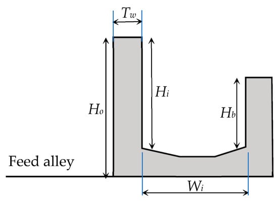
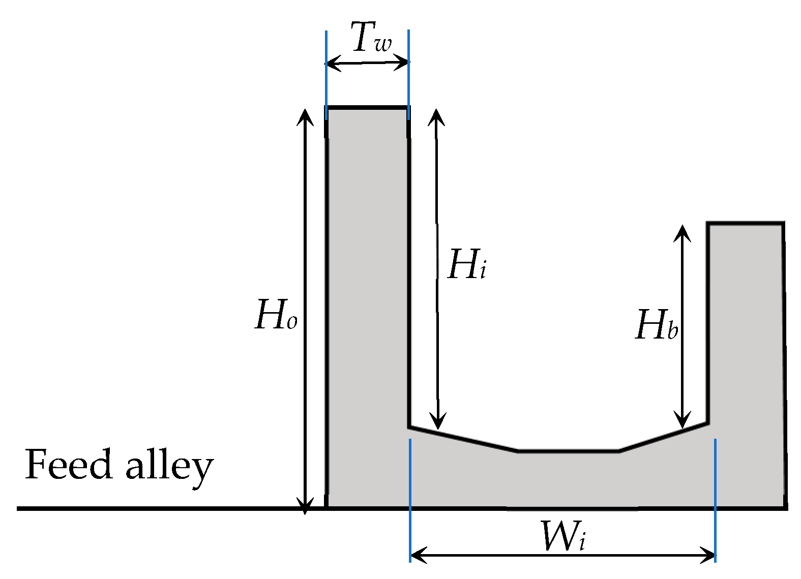
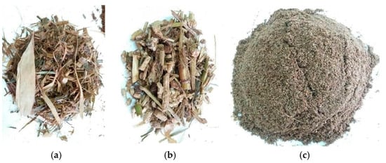
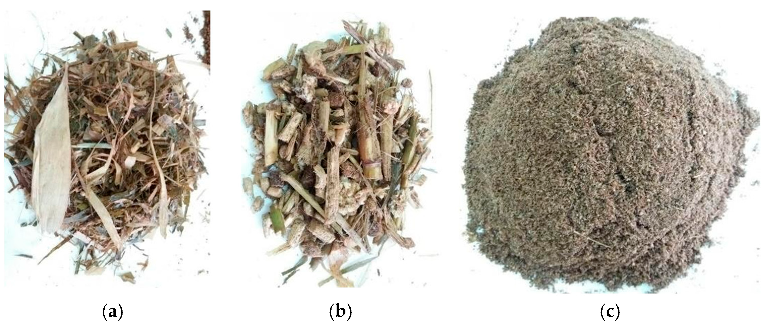
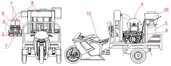
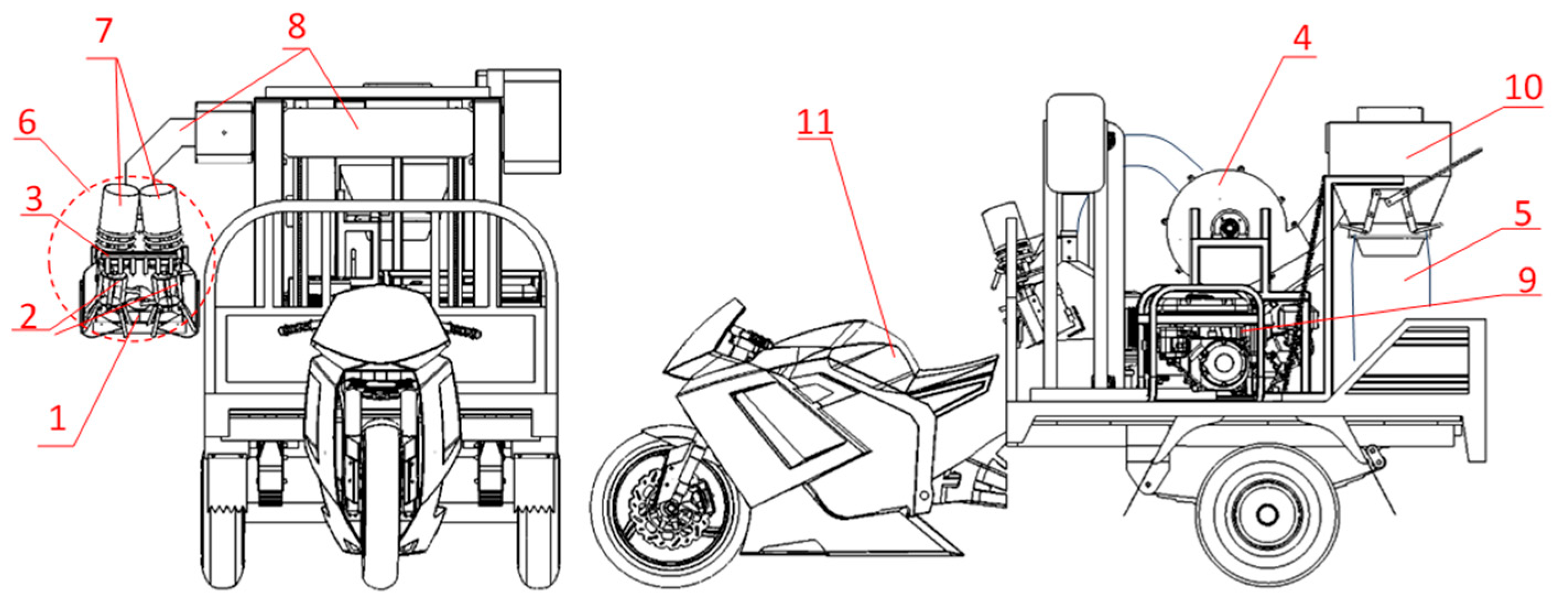
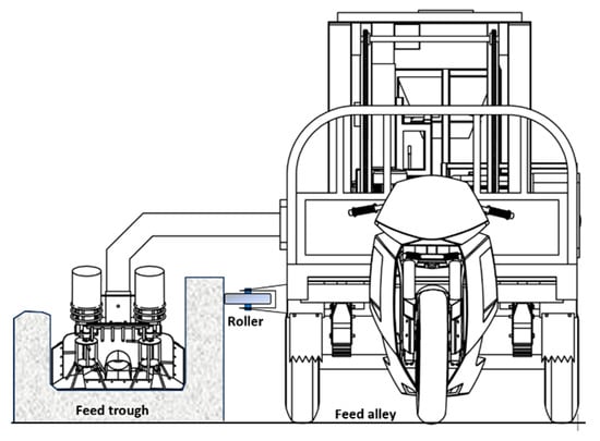
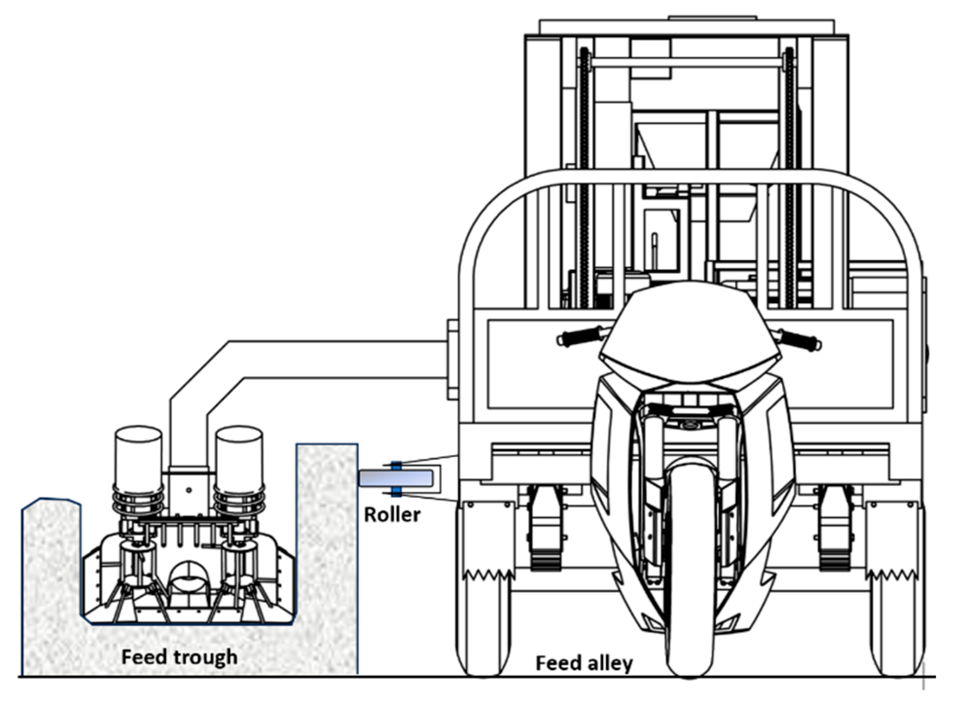
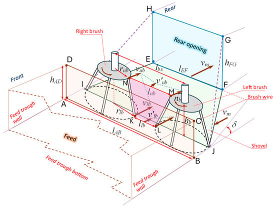
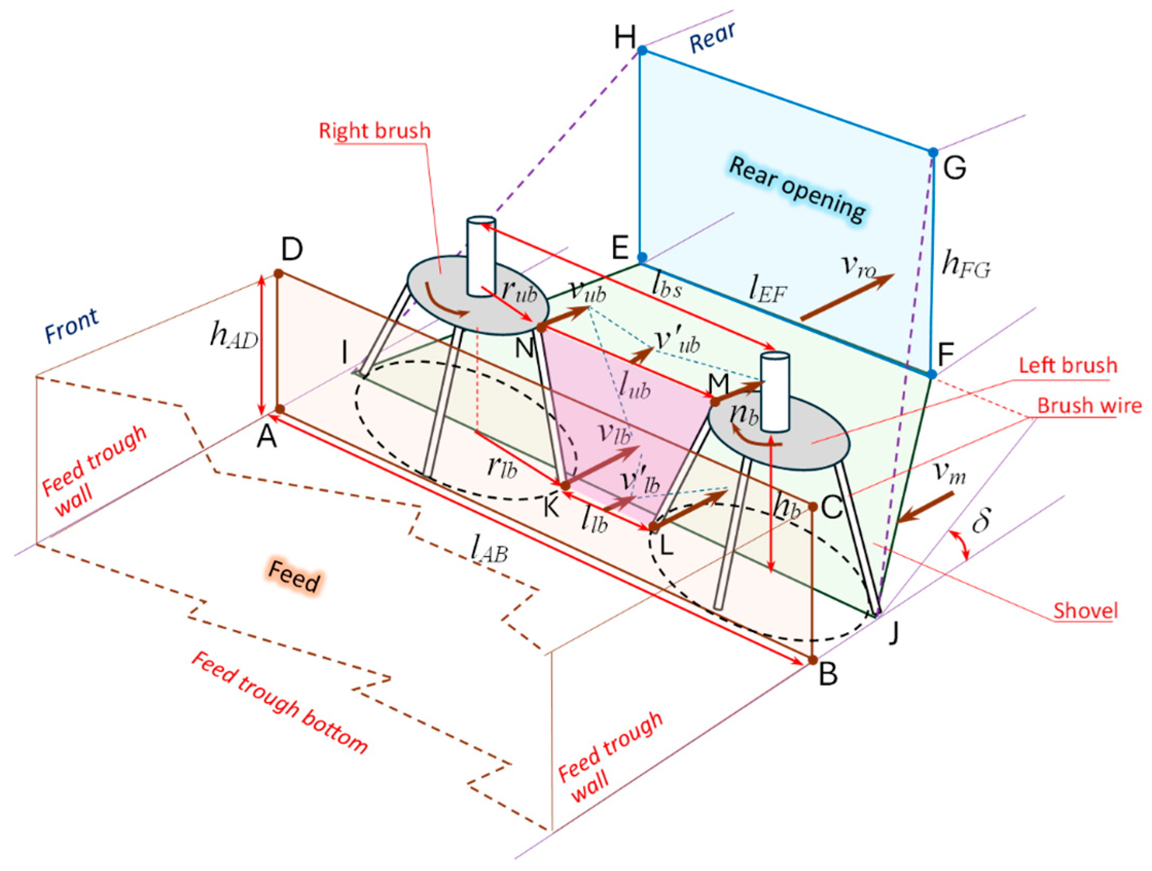
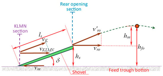
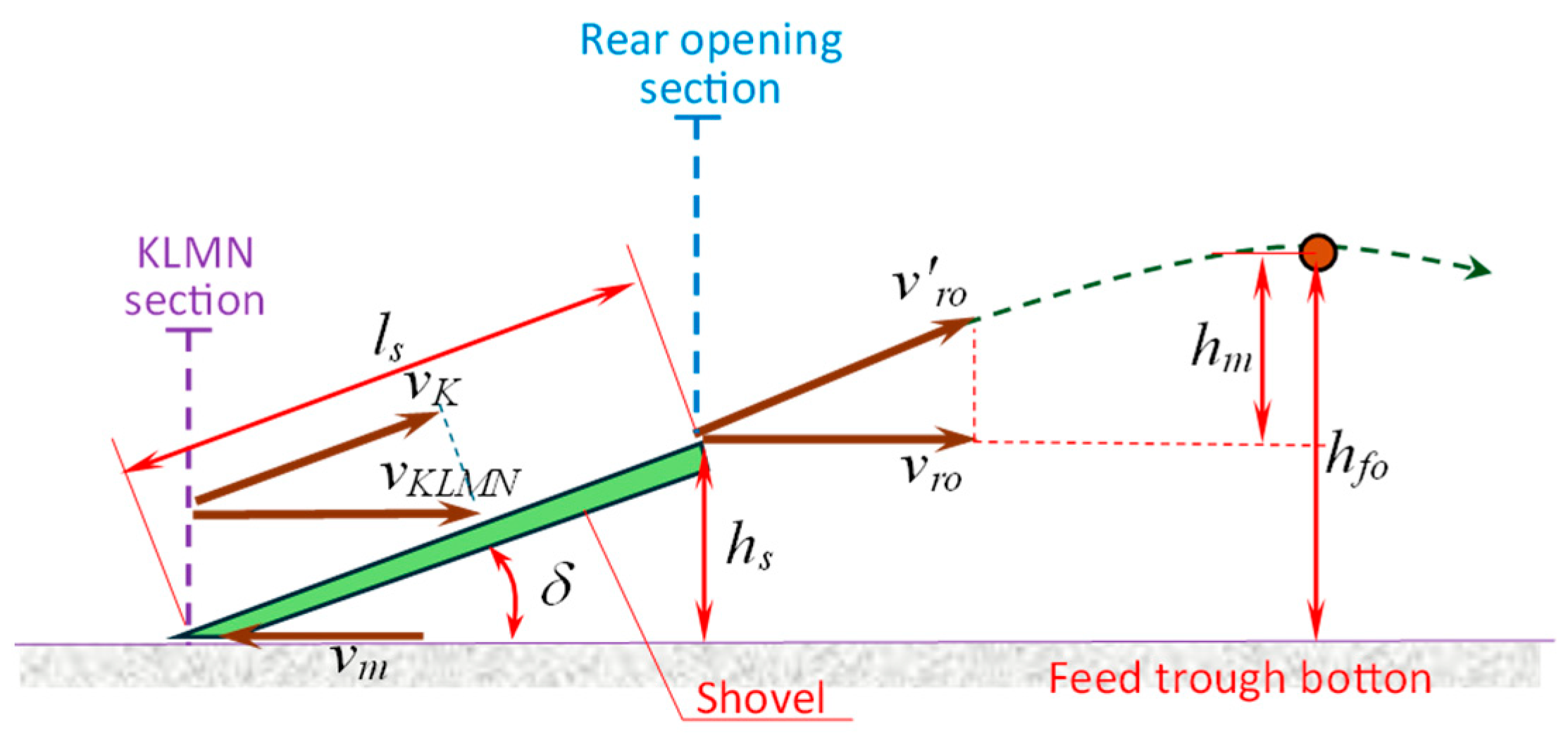
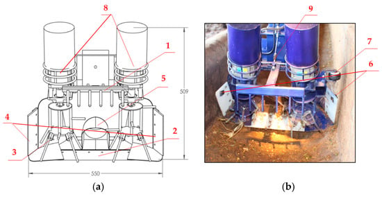
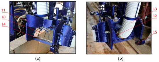
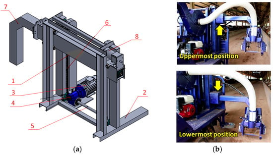
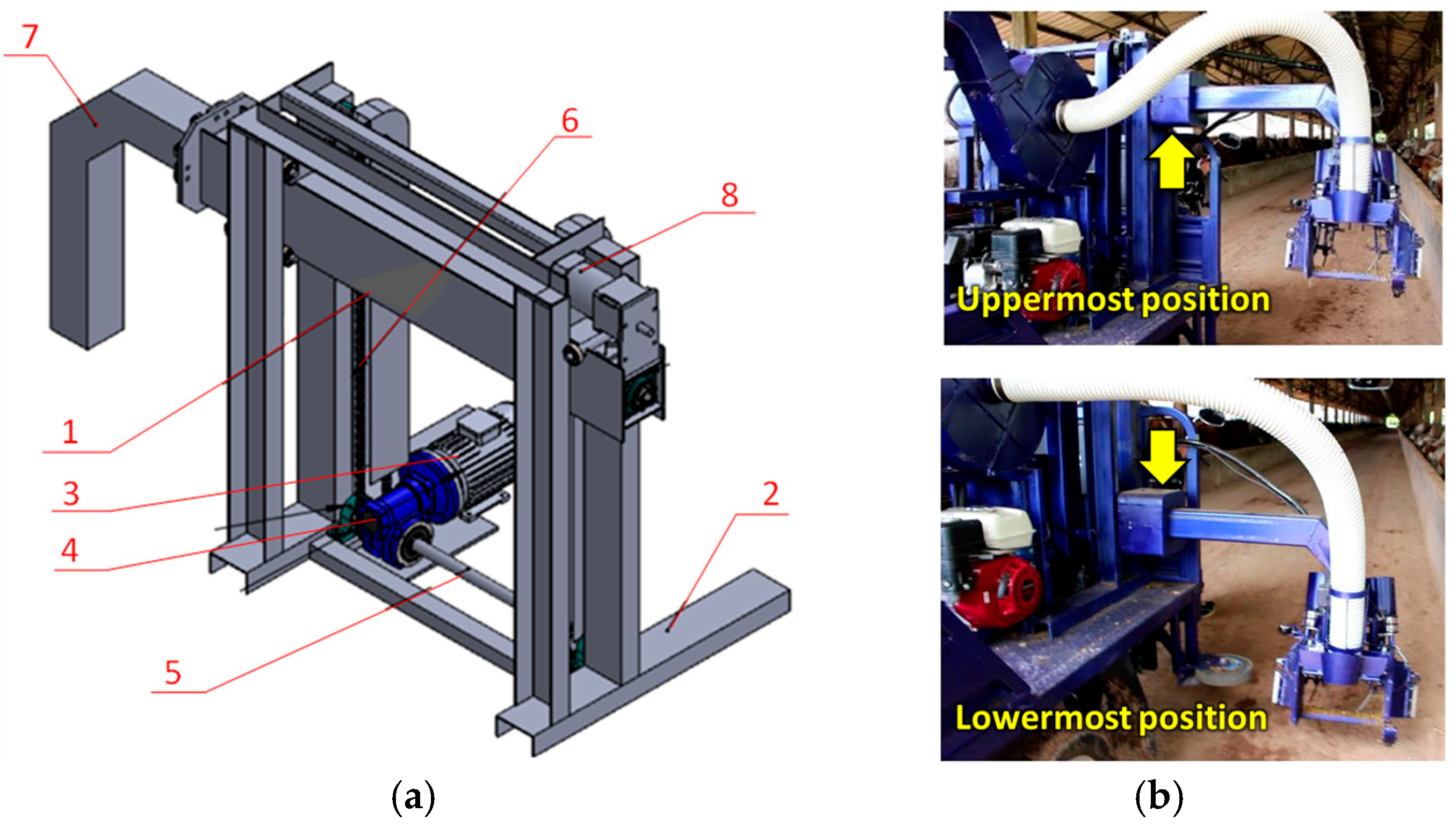
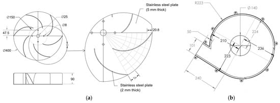
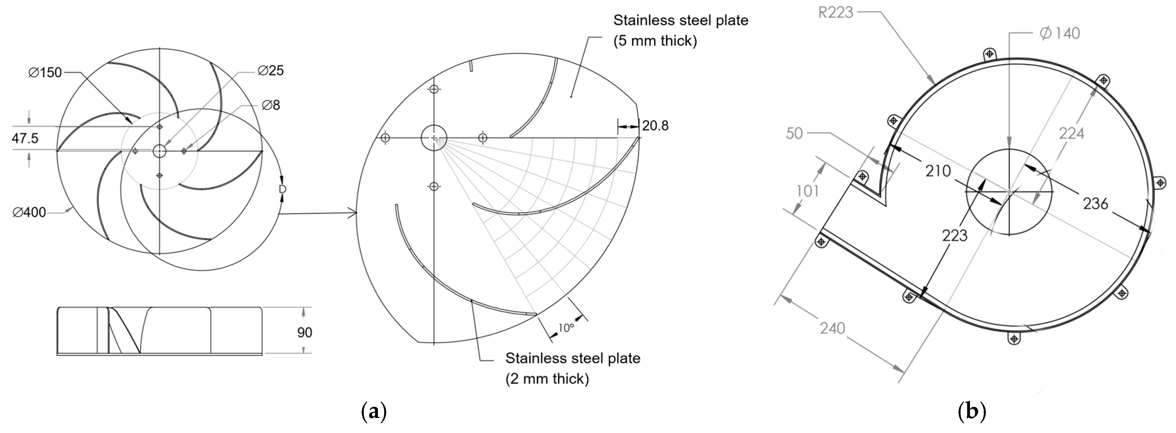
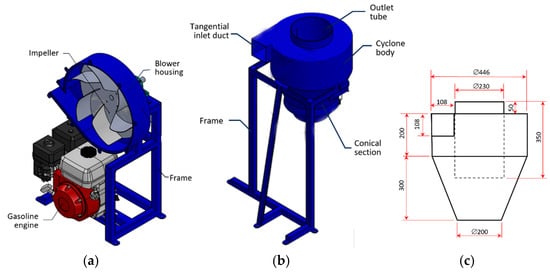
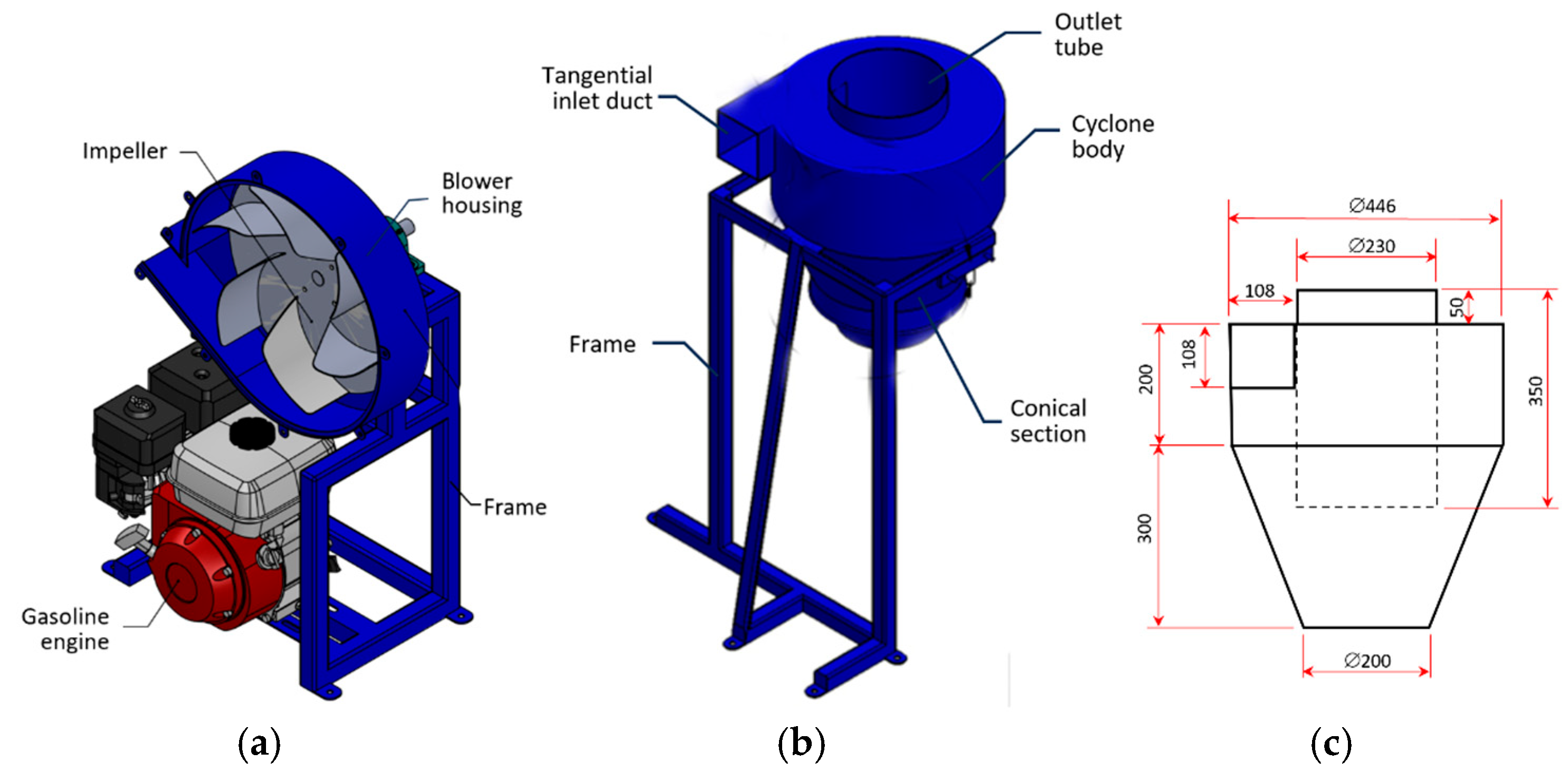
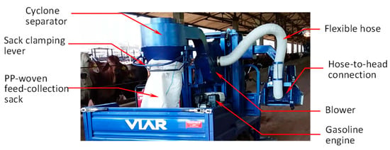
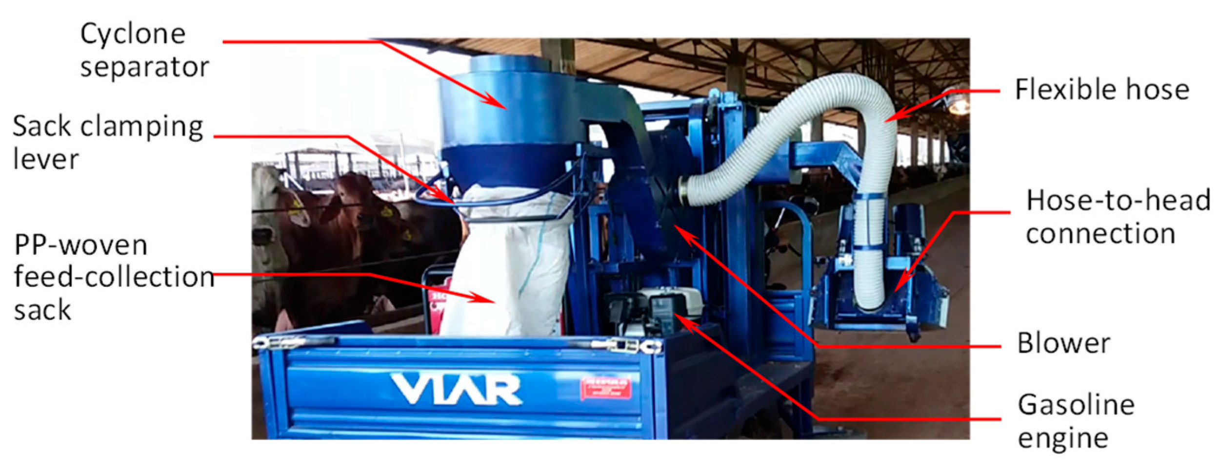
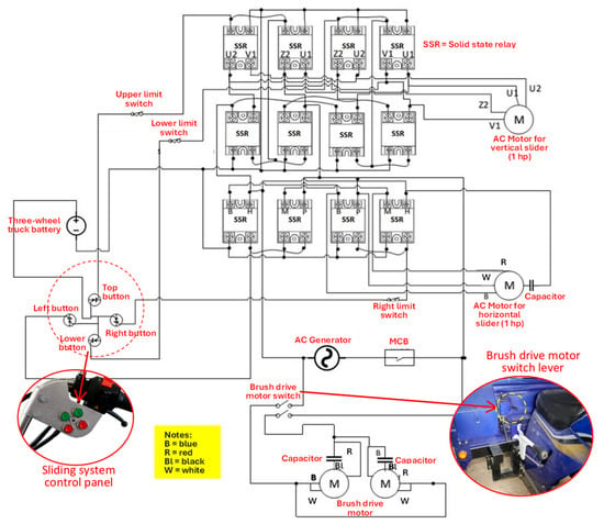
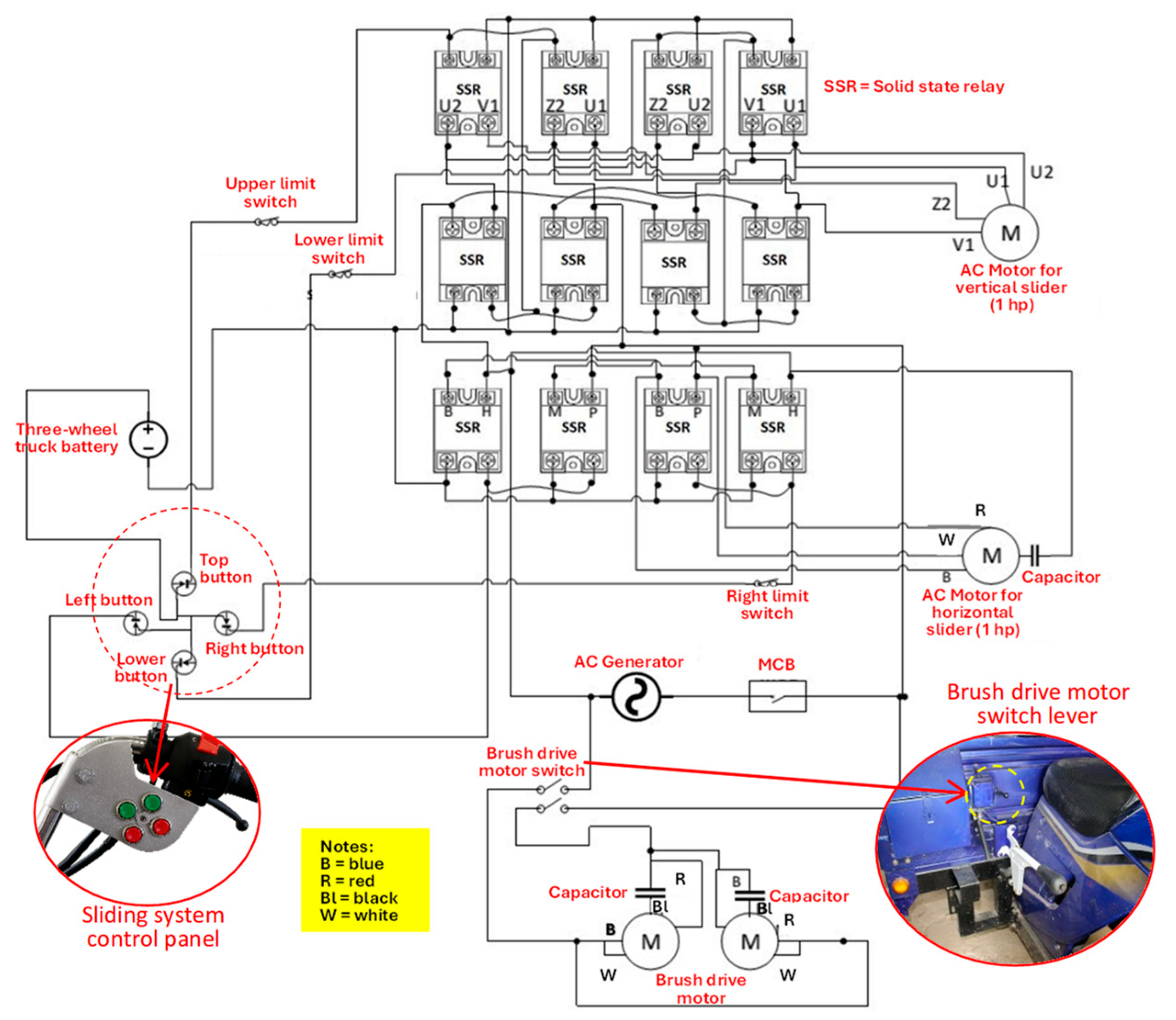
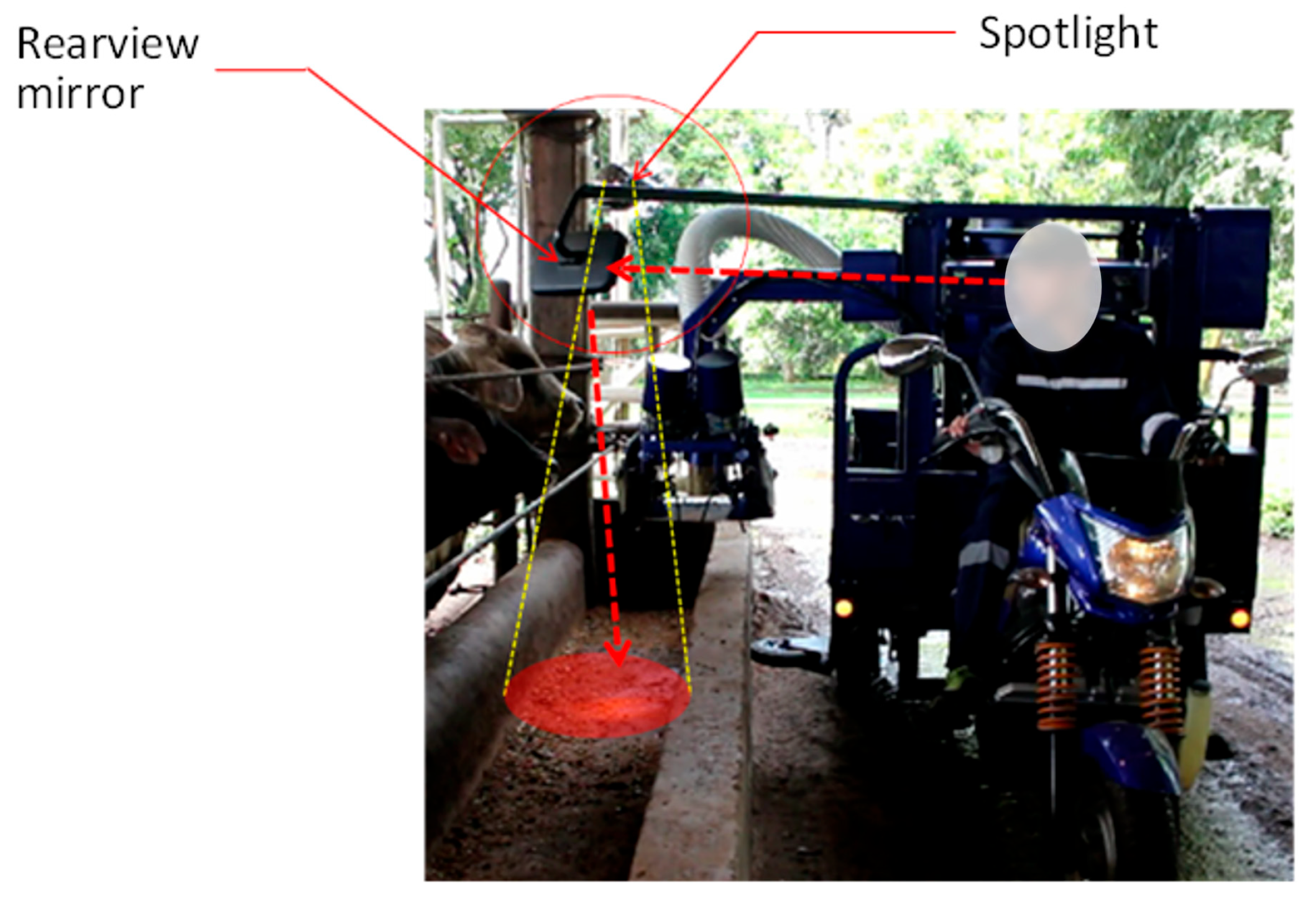
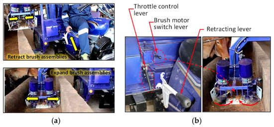
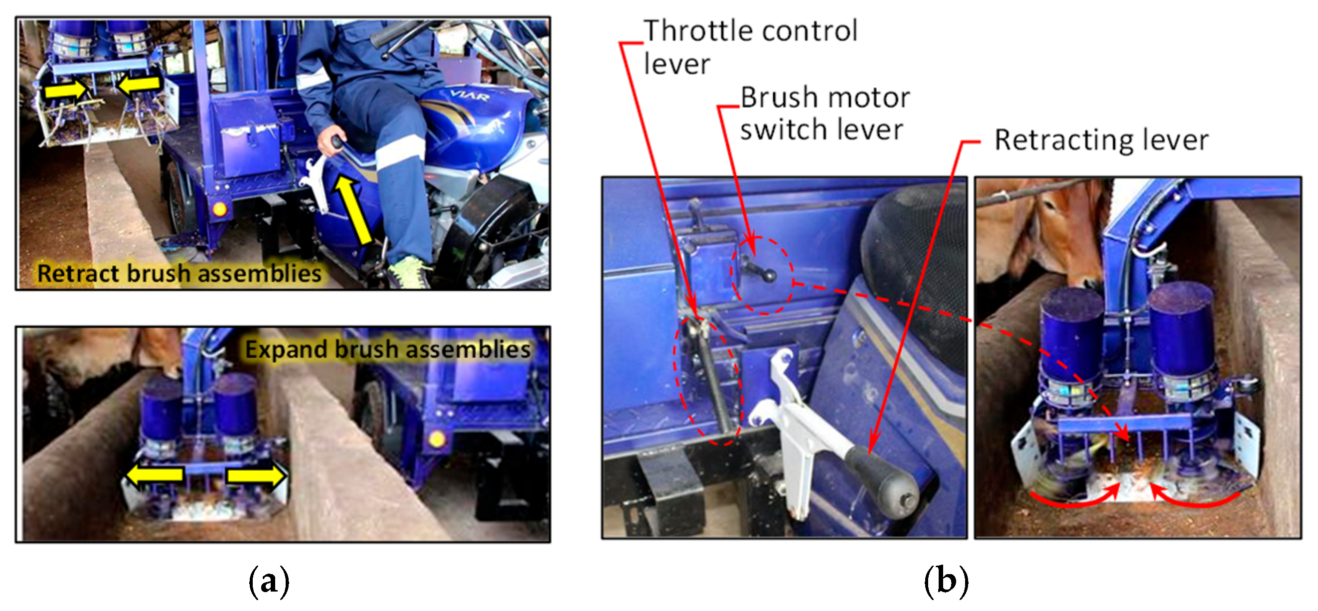
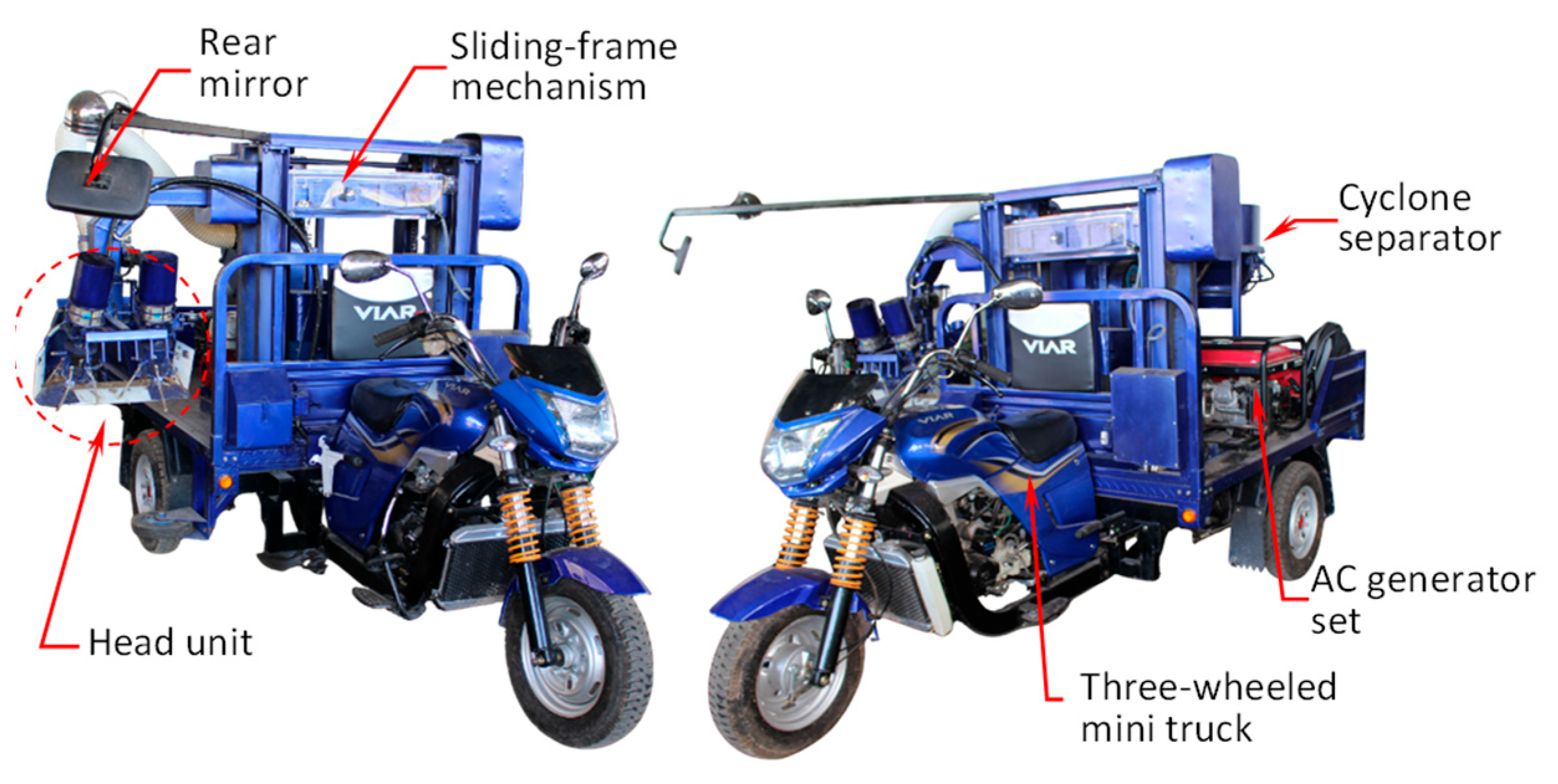
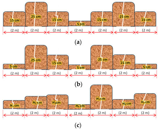
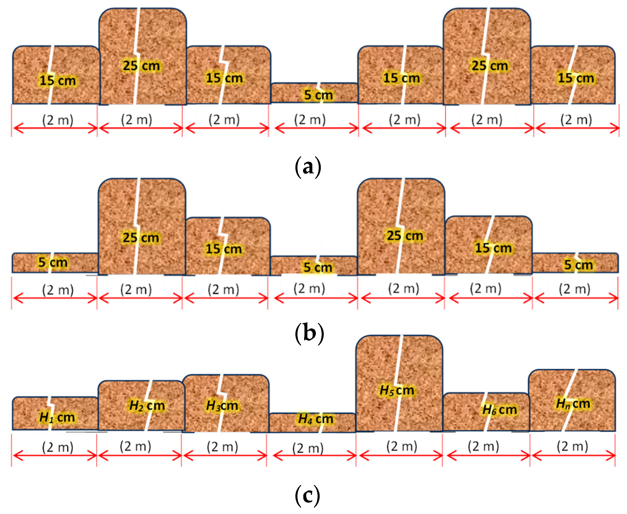
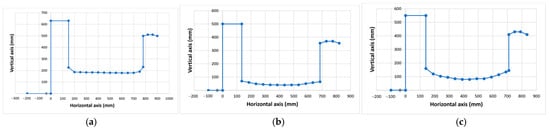
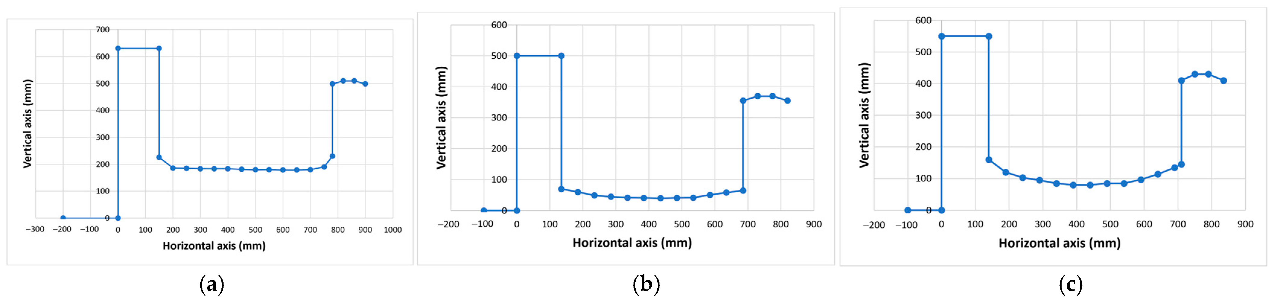
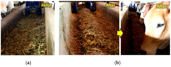
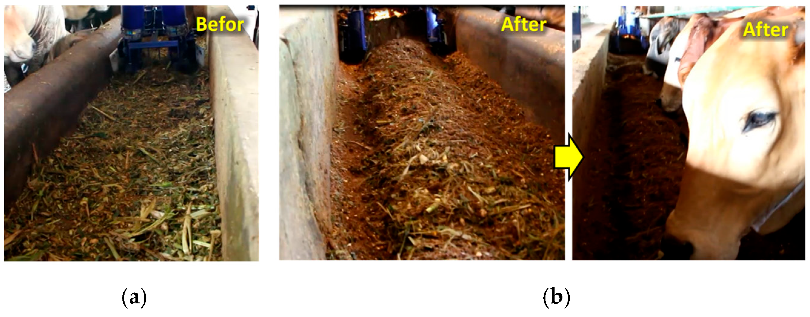

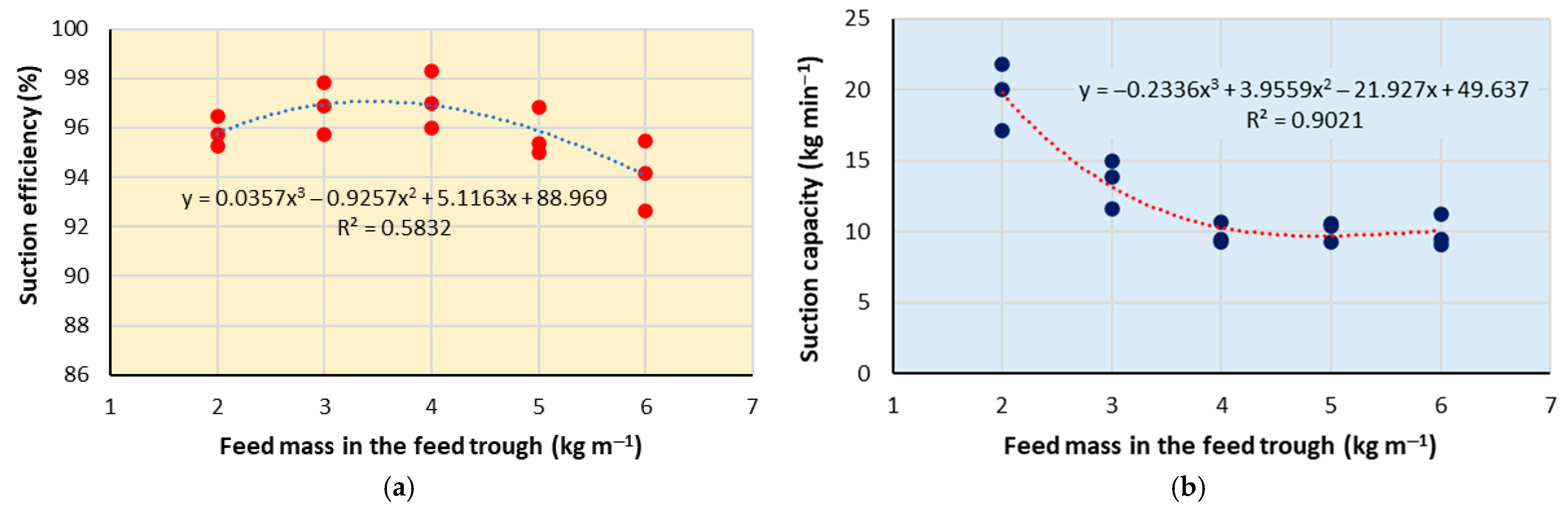
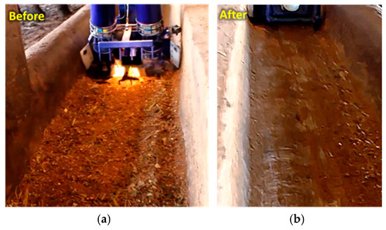
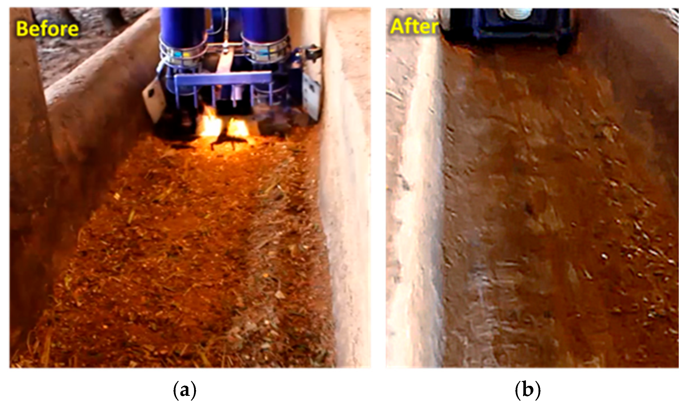

Disclaimer/Publisher’s Note: The statements, opinions and data contained in all publications are solely those of the individual author(s) and contributor(s) and not of MDPI and/or the editor(s). MDPI and/or the editor(s) disclaim responsibility for any injury to people or property resulting from any ideas, methods, instructions or products referred to in the content. |
© 2026 by the authors. Licensee MDPI, Basel, Switzerland. This article is an open access article distributed under the terms and conditions of the Creative Commons Attribution (CC BY) license.