


Abstract
The harvesting of Camellia oleifera fruit in hilly areas faces core problems such as low manual efficiency, poor terrain adaptability of existing machinery, and severe emissions and noise from traditional equipment. This study designed a crawler chassis utilizing a permanent magnet synchronous motor-driven hydraulic system. The research integrated kinematic modeling and resistance calculations for parameter matching, followed by AMESim dynamic simulations and motor calibration experiments. Finally, comprehensive field tests were conducted to evaluate the prototype. The results indicate the chassis achieves a maximum travel speed >1.5 m∙s−1, a climbing angle of 41.4°, and a turning radius of 0.72 m, with noise levels strictly below 80 dB(A). Significantly, dynamic power characteristic tests under actual vibration harvesting conditions revealed that the 45 kW motor maintains a rapid response with ample power reserve. The input power exhibited a distinct square-wave pattern synchronized with hydraulic valve commands, peaking at 18.1 kW during vibration bursts. These findings confirm the system’s stability under coupled driving and harvesting loads. This design offers a viable, low-noise solution for electrifying and intelligently upgrading Camellia oleifera harvesting equipment in complex terrains.
1. Introduction
Camellia oleifera, as an evergreen woody plant, is widely distributed in the red soil hilly regions of southern China. Its fruits hold value for edible, medicinal, and light industrial raw material purposes [1,2,3]. As the health benefits of Camellia (C.) oleifera oil gain increasing recognition, the planting area of C. oleifera in China has expanded to approximately 70 million hectares [4]. However, about 85% of C. oleifera trees are planted on gentle slopes with gradients between 5° and 25° in hilly and mountainous areas [5]. These areas feature complex terrain with uneven ground, often covered by weeds, stones, and tree roots. This challenging environment consequently leads to low efficiency and high costs in traditional manual harvesting. Furthermore, it hinders the expansion of large-scale Camellia oleifera cultivation and poses significant challenges to the terrain adaptability of harvesting equipment [6,7]. Therefore, developing efficient and reliable forestry harvesting equipment to achieve mechanized harvesting of C. oleifera fruit is crucial.
Existing agricultural and forestry harvesting equipment can be categorized into three types based on the chassis powertrain type: mechanical, hydraulic, and electric drive. Regarding mechanical drive, Manzo et al. [8] developed a continuous canopy shaker for harvesting California table olives. Their design, which employs an internal combustion engine-driven mechanical chassis, integrates shaking, harvesting, and conveying operations, boosting efficiency by over 30% compared to intermittent methods. It is suitable for high-density orchards and is easy to maintain. Homayouni et al. [9] designed a simultaneous trunk and canopy shaker to improve table olive harvesting efficiency. Their system, which relies on an internal combustion engine and mechanical transmission, enables cooperative dual-position vibration control. This method improves efficiency by 25% over trunk shaking alone and reduces localized tree damage. Du et al. [10] developed a three-dimensional vibratory harvester for tree fruit to meet multi-crop harvesting needs. This harvester uses an internal combustion engine coupled with a mechanical transmission to produce adjustable 3D vibrations. Its key advantages are a harvesting efficiency 8–10 times that of manual labor, a crawler chassis adapted to hilly terrain, and maintenance costs over 30% lower than hydraulic systems. Ma et al. [11] designed an inertia-type trunk shaker for the precise harvesting of pistachios. The shaker is equipped with an internal combustion engine-driven mechanical chassis, enabling precise vibration frequency output and transfer monitoring. It offers a vibration frequency error within ±0.5 Hz, high energy efficiency, and suitability for continuous operation in large orchards. Leone et al. [12] designed an olive trunk shaker to address parameter selection needs for efficient harvesting. Fitted with an internal combustion engine-driven mechanical chassis, the shaker provides multi-frequency gradient vibration output. Its benefits are rapid and stable frequency switching, a low fruit damage rate, and a harvesting capacity exceeding 80 trees per hour. Zhou et al. [13] designed a vibratory harvester for fragile sweet cherries. This harvester uses an internal combustion engine-driven mechanical chassis to deliver low-frequency pulse vibration. It achieves a 22% higher qualified harvest rate than traditional high-frequency equipment, along with good fuel economy and suitability for high-density orchards. Rosa et al. [14] developed a yield monitoring system integrated with a harvester to meet pistachio yield monitoring needs, enabling synchronous harvesting and data collection. The system provides accurate monitoring, reduces statistical costs, offers high load-bearing capacity, and operates reliably. This widely used type of mechanical transmission chassis offers the advantages of mature technology, extensive maintenance network coverage, low repair costs, high transmission efficiency, excellent energy consumption performance under stable speed conditions, and strong overload capacity, making it suitable for heavy-duty machinery.
As to hydraulic drive, Pu et al. [15] developed a two-section, variable-frequency canopy shaker for precise citrus harvesting. Mounted on an internal combustion engine-driven hydraulic chassis, the shaker delivers targeted vibrations to different canopy zones. This design provides good vibration buffering to reduce tree damage, along with flexible steering and high operational precision. Bentaher et al. [16] designed a harvester with an internal combustion engine-driven hydraulic chassis to optimize vibration energy transfer for olive harvesting, and they conducted finite element modeling. The resulting system ensures smooth energy transfer, reduces tree recovery time by 30%, provides comprehensive overload protection, and adapts to varying planting densities. Hu et al. [17] designed a new hydraulic chassis for rice transplanters based on operational requirements. Their design adopted a single-pump, four-motor powertrain scheme, and its feasibility and reliability were verified through paddy field experiments. Yang et al. [18] developed a crawler-type harvester adapted to the local planting and growth characteristics of red cluster peppers. Their detailed study of the hydraulic system identified key factors affecting picking efficiency. Xiao et al. [19] designed a dedicated hydraulic chassis for paddy field operation to overcome challenges like poor travel stability and insufficient power in traditional weeders. Tests showed that this chassis exhibits good dynamic performance and stability, achieving average deviation and grain slip rates of 2.61% and 3.59%, respectively. This type of hydraulic transmission chassis offers flexible layout, enabling remote placement of actuators, stepless speed regulation, and overload protection functions.
Regarding electric motor drive, Wen et al. [20] investigated a pure electric wheel-drive tractor to address the problems of excessive emissions and low traction efficiency in traditional diesel tractors. The proposed combined traction and ballast control method improved traction efficiency by 3.7%, reduced slip by 15.05%, and lowered total drive motor energy consumption by 4.9%. Fu et al. [21] developed a compact and lightweight electric four-wheel-drive chassis for a seeding robot used in soybean and corn strip planting. Their design mitigates key issues associated with traditional tractors, including soil compaction, reduced fertility, pollution from non-clean fuels, and hindrances to sustainable development. Zhou et al. [22] designed a self-propelled electric sprayer chassis to combat poor speed stability and declining spray quality, which are exacerbated by changing road slopes and decreasing liquid tank mass. The system combines an upper PID controller and a lower fuzzy PID controller for overall control. Xie et al. [23] proposed a novel drive system for electric tractors—comprising dual motors and a coupled powertrain—to enhance load capacity and operational efficiency. The research concluded that this system provides sufficient loading capacity for large loads under typical conditions and significantly improves operational efficiency. He et al. [24] developed a four-wheel-steering (4WS) electric chassis notable for its small turning radius and high maneuverability. This configuration utilizes coordinated differential motor control to achieve simultaneous steering and propulsion, thereby eliminating the need for a dedicated steering servo and reducing steering torque relative to traditional designs. The advantages of such pure electric chassis include significantly improved energy efficiency, precise control enabled by electronic systems, and low emission and noise levels during operation, aligning with the development trends of green agriculture. These studies provide references for research on chassis suitable for C. oleifera fruit harvesters in hilly and mountainous areas.
In order to address the challenges posed by poor adaptability of harvesting equipment and emissions/noise pollution from traditional machinery during C. oleifera fruit harvesting operations in hilly and mountainous areas, this study focuses on the design of a motor-driven hydraulic crawler chassis. This design uses an electric motor to replace the internal combustion engine as the power source, effectively addressing emission and noise pollution. Then, the power distribution through a hydraulic system overcomes inherent drawbacks of mechanical transmission such as layout rigidity and stepped speed changes with power interruption during gear shifts. Furthermore, by using an electric motor to drive the hydraulic system, which then powers the hydraulic travel motor, this design avoids the need for an excessively high-power motor that a purely motor-driven chassis would require. Although direct electric drive (e-drive) theoretically offers superior energy efficiency, the motor-hydraulic coupling scheme was selected for this specific unstructured forestry environment. The hydraulic transmission’s inherent damping properties effectively absorb severe impact loads from hidden roots and rocks—conditions where rigid direct-drive motors are vulnerable. Additionally, hydraulic motors naturally provide the low-speed, high-torque output required for climbing steep slopes and reliable parking without complex reduction gearing. Given the current infrastructure in remote mountainous regions, hydraulic systems also offer superior maintainability compared to high-voltage electric drives.
Aiming to achieve stable, efficient, and green operation of the harvester in complex terrain, this study focuses on the powertrain system design and travel performance optimization of the chassis. The main contributions of this study are as follows.
(1) This study proposes a motor-driven hydraulic crawler chassis scheme, focusing on the design of its motor-hydraulic hybrid powertrain system. The dynamic characteristics during travel and steering are analyzed by establishing kinematic and traveling resistance models for the chassis, and key component parameters are determined.
(2) This study builds a hydraulic system model of the chassis on the AMESim simulation platform to deeply analyze the dynamic output characteristics and stability of the system under different motor speeds. Subsequently, a motor dynamometer test platform was set up to calibrate the motor’s external characteristic curve, thereby determining the optimal operating parameters for the motor-hydraulic powertrain.
(3) Through field tests, the chassis performance is comprehensively evaluated in terms of travel, climbing, and maneuverability. Furthermore, this study uniquely characterizes the dynamic power consumption profile under actual vibration harvesting conditions. By monitoring the real-time input power and response of the central motor, the reliability of the power-sharing system between chassis propulsion and harvesting mechanisms is verified, providing a benchmark for the power matching of multi-load forestry machinery.
2. Materials and Methods
2.1. Overall Chassis Design and Working Principle
This study proposes a crawler chassis scheme that integrates electric motor and hydraulic transmission. Its core lies in utilizing motor drive for clean energy application and achieving flexible power distribution and precise control through hydraulic transmission.
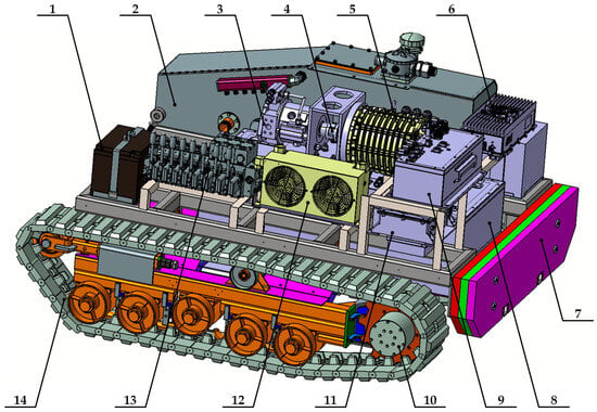
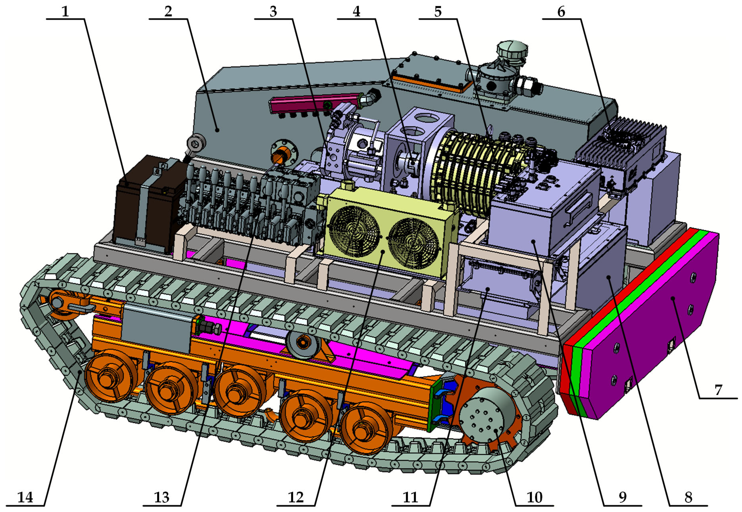
The overall structure of the motor-driven hydraulic crawler chassis (see Figure 1) is primarily composed of a motor drive system, a hydraulic powertrain, and a crawler travel mechanism. The motor drive system serves as the power source, primarily including the motor, battery pack, motor controller, battery management system, DC-DC converter, and battery. The hydraulic powertrain acts as the power transfer and distribution hub, mainly comprising the hydraulic pump, hydraulic directional valve, and hydraulic motor. The crawler travel mechanism, as the actuating mechanism, adopts a “four wheels and one track” structure, responsible for supporting the entire machine’s mass and enabling travel functions. The entire machine employs a compact layout with a low center of gravity, achieved by arranging heavy components like the battery pack and hydraulic oil tank at the bottom of the frame. Additionally, the design of the counterweight plate further enhances longitudinal stability during climbing. The main design parameters of the chassis are shown in Table 1.
Figure 1.
Structural design of the C. oleifera fruit harvester chassis. 1—Battery. 2—Hydraulic oil tank. 3—Hydraulic pump. 4—Coupling. 5—Motor. 6—DC-DC converter. 7—Counterweight plate. 8—Battery pack. 9—Battery management system. 10—Hydraulic motor. 11—Motor controller. 12—Cooling fan. 13—Hydraulic directional valve. 14—Crawler travel mechanism.
Table 1.
Main parameters of the motor-driven hydraulic crawler chassis.
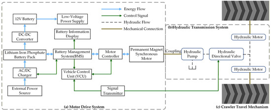
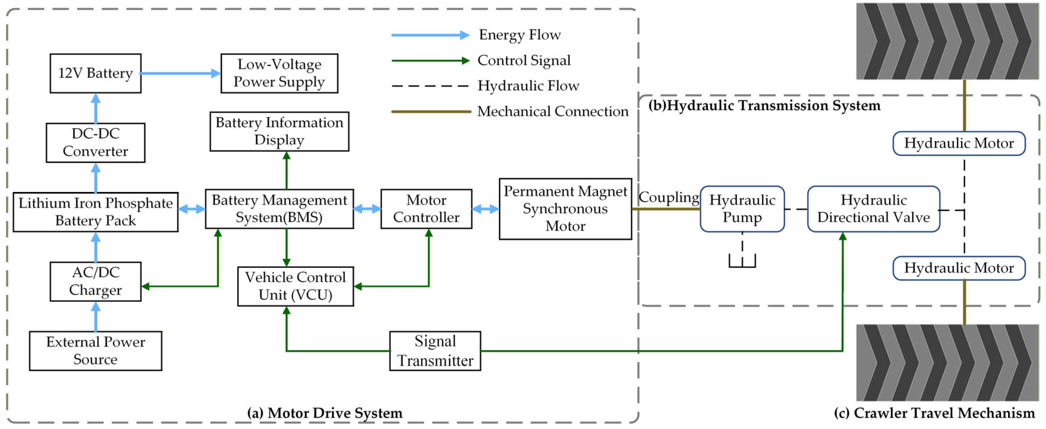
The system schematic of the motor-driven hydraulic crawler chassis is shown in Figure 2, and its power flow and control logic can be described as follows. The entire chassis is powered by a lithium iron phosphate battery supplying 307 V high-voltage DC power. This electrical energy is managed by the Battery Management System (BMS) and the Motor Controller (IPU) to drive the permanent magnet synchronous motor into rotation. The motor directly drives the hydraulic pump via a coupling, converting electrical energy into hydraulic energy in the form of high-pressure hydraulic oil. The high-pressure hydraulic oil is directed by a solenoid-operated directional valve bank, which controls its flow direction and rate. The hydraulic oil then drives the hydraulic motors on both sides, converting hydraulic energy into mechanical energy. Finally, the power is transmitted to the drive wheels through a built-in reduction gearbox. The drive wheels engage with the rubber tracks to ultimately propel the entire chassis, enabling travel, steering, and other functions. The Vehicle Control Unit (VCU) serves as the core for intelligent control and energy management of the whole machine. On one hand, it needs to receive operational commands from the signal transmitter; on the other hand, it is responsible for coordinating the Battery Management System (BMS) and the Motor Controller. In addition to cooperating with the VCU, the BMS is responsible for monitoring battery status (such as voltage, temperature, State of Charge, etc.) and relaying this information to the battery information display screen. Meanwhile, the DC/DC converter can transform the 307 V high-voltage DC power from the lithium iron phosphate battery into low-voltage DC power to charge the 12 V storage battery. This storage battery is dedicated to supplying power for low-voltage loads, such as the cooling fan and the hydraulic solenoid directional valves. Via the AC/DC charger, an external AC power source can be converted to a suitable DC voltage to replenish the energy of the lithium iron phosphate battery pack.
Figure 2.
Schematic diagram of the motor-driven hydraulic crawler chassis for the C. oleifera fruit harvester.
2.2. Chassis Travel Mechanism Design
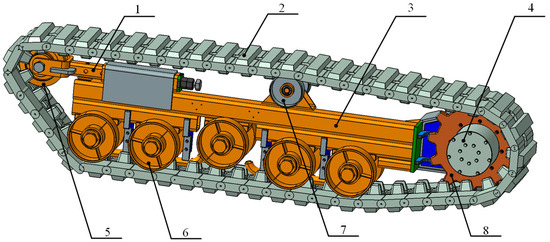
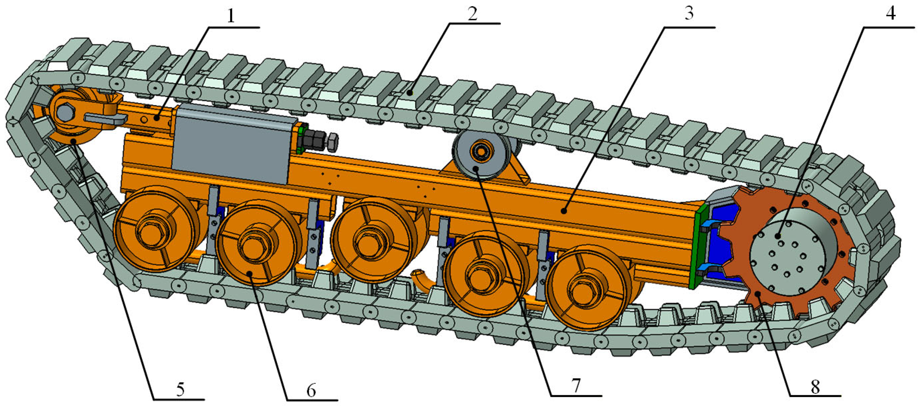
To adapt to the rugged terrain of hilly and mountainous areas, this study designed a crawler travel mechanism based on the “four wheels and one track” configuration, as shown in Figure 3. This mechanism consists of the drive wheel, carrier rollers, tension wheel, track rollers, rubber track, tensioning device, frame, and the hydraulic motor integrated on the drive wheel side. Its core function is to support the harvester’s total mass and convert the hydraulic motor’s rotational output into linear track movement via the drive wheel. Through this mechanism, the necessary traction and obstacle-crossing capability for the entire machine are provided.
Figure 3.
Schematic diagram of the crawler travel mechanism. 1—Tensioning device. 2—Rubber track. 3—Frame. 4—Hydraulic motor. 5—Tension wheel. 6—Carrier roller. 7—Track roller. 8—Drive wheel.
Through comprehensive calculation of key indicators such as ground pressure, maximum traction, and overall machine stability, the main structural parameters of the travel mechanism were determined, as shown in Table 2. Rubber tracks were selected to reduce damage to the road surface and minimize operational noise. The determined track gauge and contact length aim to optimize steering performance and travel stability [25].
Table 2.
Parameters of the crawler travel mechanism.
2.3. Kinematic Analysis of the Chassis
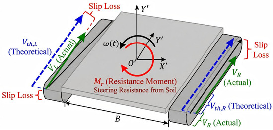
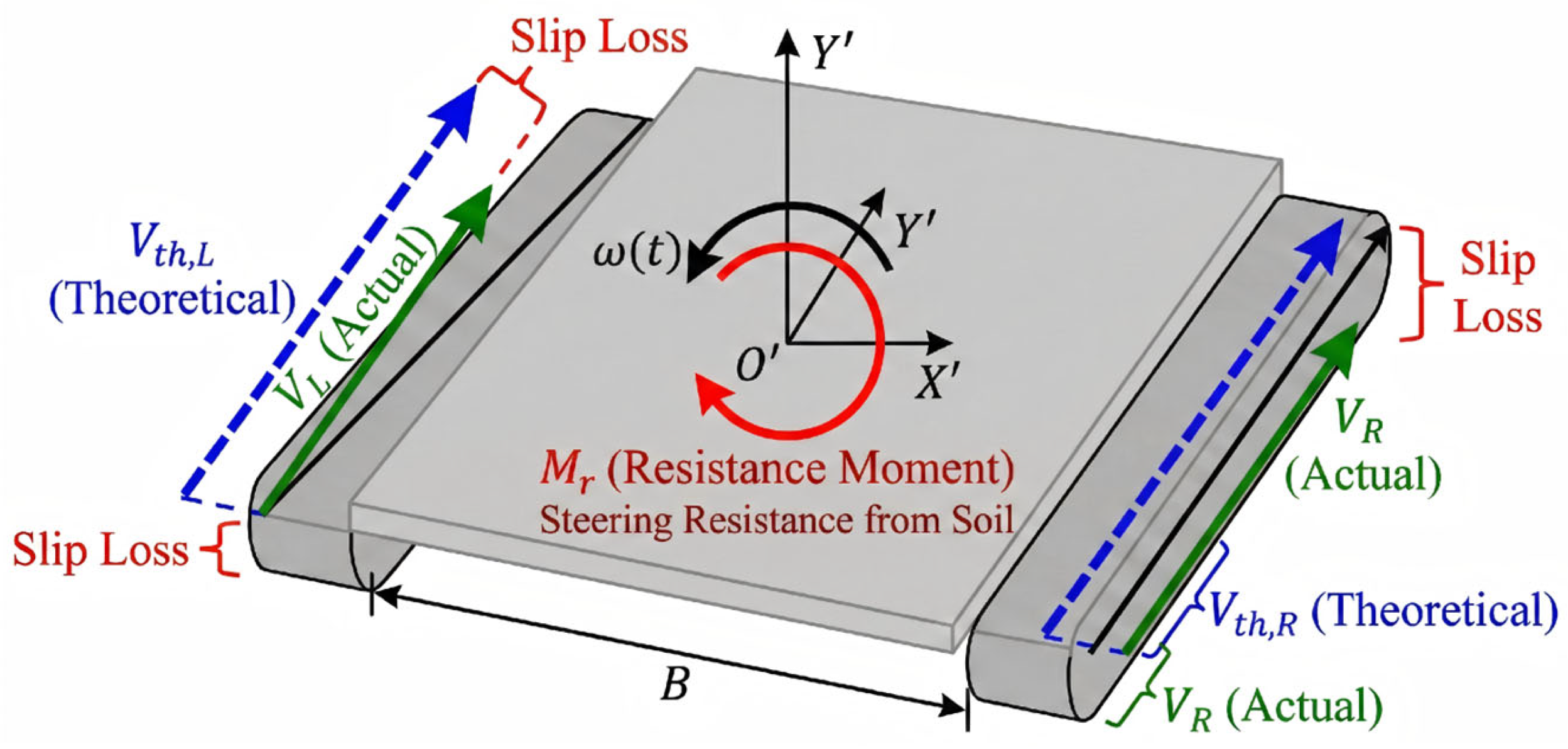
To accurately match the powertrain parameters and ensure precise trajectory control in complex hilly terrain, this study established a comprehensive kinematic and dynamic model. The chassis utilizes a distributed drive architecture where a central electric motor drives the hydraulic pump, while two independent hydraulic motors directly drive the left and right tracks. Therefore, the motion trajectory is determined by the output speeds of these two hydraulic motors.
As illustrated in Figure 4, the global coordinate system is denoted as , and the relative coordinate system fixed to the chassis center of mass is . The pose of the chassis at time is represented by the vector .
Figure 4.
Kinematic model of the motor-driven hydraulic crawler chassis.
First, the theoretical linear speeds of the left and right tracks, denoted as and , are directly proportional to the instantaneous rotational speeds of the hydraulic motors, as shown in Equation (1).
where and are the rotational speeds of the left and right hydraulic motors at time , r∙min−1; is the drive wheel radius, m; is the mechanical reduction ratio.
However, on deformable agricultural terrain, the actual forward speed is inevitably reduced by track slip. To quantify this, the time-varying slip ratio is introduced. The actual track speeds and are expressed as shown in Equation (2).
where and represent the instantaneous slip ratios of the left and right tracks, respectively. This equation reveals a critical energy coupling mechanism: the actual travel speed is dynamically coupled with the soil shear properties. The term acts as a “velocity efficiency factor,” indicating that the system must reserve sufficient hydraulic flow and pressure margin to overcome the shear power loss () inherent in soft red clay.
Based on the instantaneous center of rotation (ICR) principle, the actual angular velocity is determined by the difference in actual track speeds and the track gauge , as shown in Equation (3).
where is the angular velocity, rad∙s−1; and is the track gauge, m.
Consequently, the instantaneous turning radius is derived as shown in Equation (4).
where is the turning radius, m. Equation (4) theoretically uncovers the root cause of trajectory deviation under open-loop control. It demonstrates that the steering radius is highly sensitive to the differential slip (). Even if the operator adjusts the valve opening to set symmetric hydraulic motor speeds (), heterogeneous soil properties can induce asymmetric slip. This implies that without real-time feedback compensation, the actual turning radius will theoretically deviate from infinity (straight line) to a finite value, making path drift an inevitable phenomenon on soft terrain.
For the chassis to perform the steering maneuver, the hydraulic motors must generate sufficient torque to overcome the Steering resistance moment . According to terramechanics theory, this resistance is calculated as shown in Equation (5).
where is the steering resistance moment, N∙m; is the coefficient of lateral resistance; is the chassis mass, kg; is the gravitational acceleration, m∙s−2; and is the track ground contact length, m.
This dynamic constraint indicates that the steering load is constant and independent of the turning radius. is proportional only to the chassis weight () and track length (). Therefore, during spot turns (), the hydraulic motors are required to output peak torque to overcome this static resistance, validating the “low-speed, high-torque” selection criterion for the hydraulic motors.
Finally, the kinematic differential equations (state-space model) describing the trajectory evolution are established as shown in Equation (6).
Integrating Equation (6) yields the precise trajectory of the chassis center of mass, as shown in Equation (7).
In summary, the analysis above indicates that the posture change rate is jointly determined by the control inputs (hydraulic motor speeds , ) and the environmental disturbances (slip ratios , ). The differential equation system in Equation (6) explicitly reveals that the mapping between operator commands and system outputs is non-linear and coupled with soil deformation. Consequently, the motion control problem requires precise regulation of the hydraulic motors as primary actuators, while recognizing that the accuracy of open-loop control is theoretically limited by the time-varying slip characteristics of the operating environment.
2.4. Chassis Traveling Resistance Calculation
To accurately match the powertrain system parameters and ensure the chassis possesses sufficient traction under typical operating conditions, this study established a traveling resistance model based on tracked vehicle ground mechanics theory [26]. The force analysis is conducted for two typical operating conditions: uniform travel on level ground and climbing a slope. This aims to provide a theoretical basis for the subsequent power selection of hydraulic motors and the drive motor.
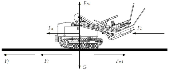
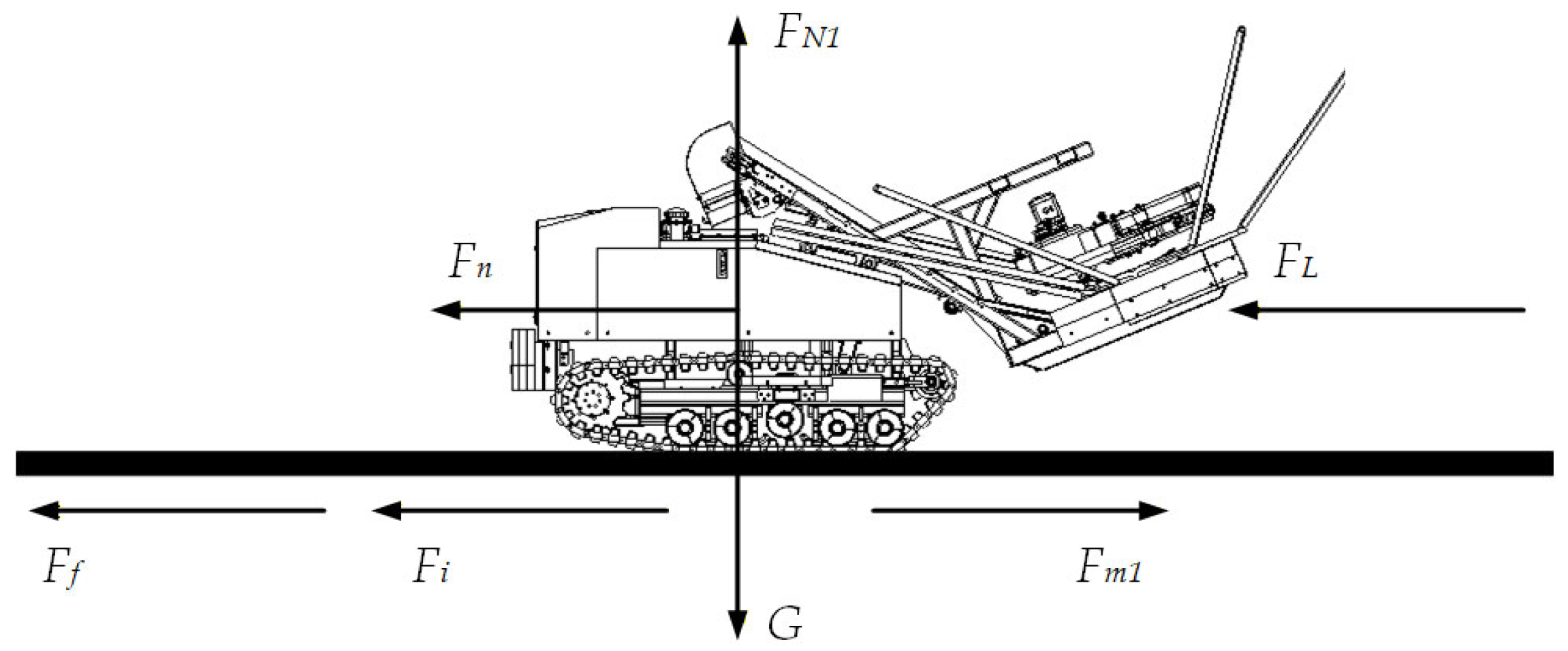
When the crawler chassis travels uniformly on a straight, level road, it primarily overcomes internal friction resistance, rolling resistance, and inertial resistance. Its force diagram is shown in Figure 5. At this point, the chassis is in a state of force equilibrium, meaning the traction force equals the sum of all resistances.
Figure 5.
Force diagram of the C. oleifera fruit harvester traveling on level ground.
The force balance equations are shown in Equations (8) and (9).
where is the internal friction resistance of the crawler chassis, N; is the rolling friction resistance between the track and ground, N; is the inertial resistance during chassis acceleration, N; is the ground support force on the crawler chassis, N; is the gravity of the crawler chassis, taken as 14,700 N; is the air resistance during travel. Due to the low travel speed of the chassis, air resistance is minimal and can be neglected.
The various resistances are given by Equations (10)–(12).
where is the internal friction coefficient, typically taken as 0.03~0.08; is the rolling friction resistance coefficient, taken as 0.09~0.12 for soft soil roads.
Considering the above resistances, the maximum traction force required for the crawler chassis during straight-line travel on level ground is calculated to be 3675 N. The corresponding total torque on the drive wheel is 551.25 N∙m. Therefore, the torque required for a single drive wheel is 275.63 N∙m, meaning a single hydraulic motor needs to provide an output torque of 275.63 N∙m.
According to the set straight-line travel speed of the crawler chassis of 1.5 m∙s−1, converted to angular velocity is 10 rad∙s−1. Thus, the drive wheel rotational speed is 95.49 r∙min−1, The output power required from a single hydraulic motor for the motor-driven C. oleifera fruit harvester traveling straight on level ground is as shown in Equation (13).
where is the safety factor, taken as 1.4; is the efficiency of the transmission device, taken as 0.9; The calculated power required for level ground travel is 4.29 kW.
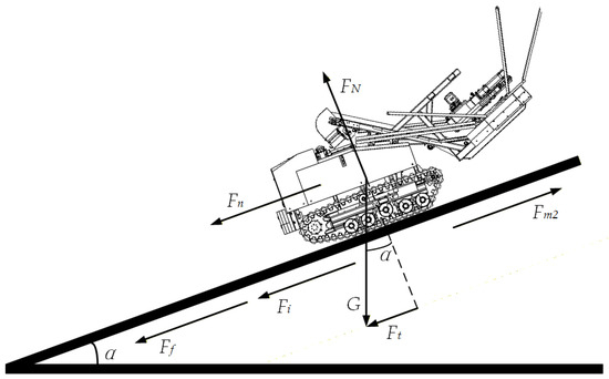
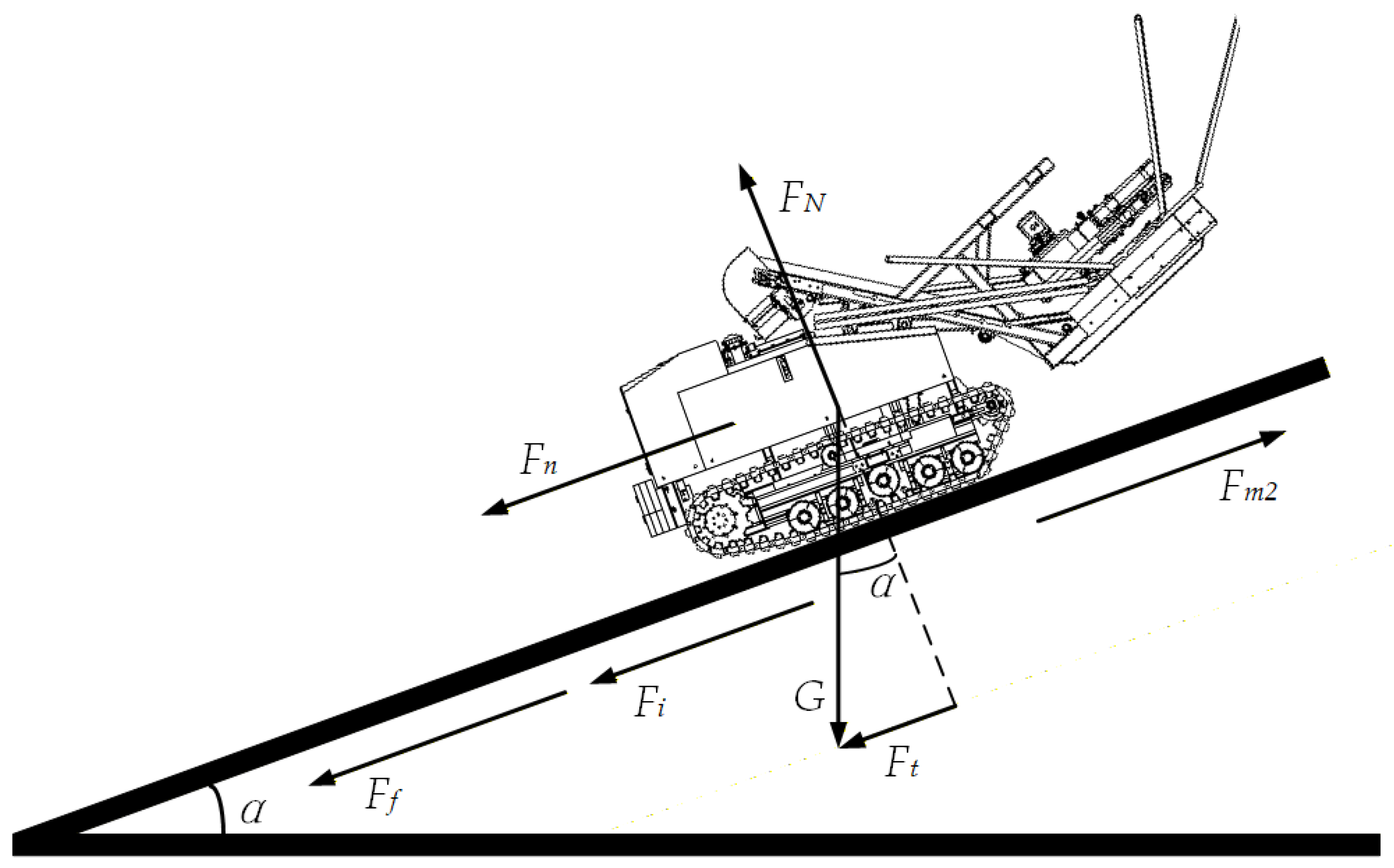
When the C. oleifera fruit harvester operates in hilly and mountainous areas, the climbing condition is the decisive operating mode for the powertrain system. The force diagram of the chassis climbing a slope is shown in Figure 6. In this case, it must also overcome the component of gravity acting parallel to the slope.
Figure 6.
Force diagram of the motor-driven C. oleifera fruit harvester climbing a slope.
The force balance equation for the crawler chassis at this time is given by Equation (14).
where the climbing resistance is generated by the component of the entire machine’s gravity along the slope direction, calculated as shown in Equation (15).
where is the maximum climbable slope angle, 25°; The calculated climbing resistance is 6212.49 N.
The maximum traction force required for the chassis to climb the slope is 9887.49 N. The drive wheel radius is 0.15 m, so the torque required for a single drive wheel is 741.56 N∙m. Assuming the crawler chassis climbing speed is 1 m∙s−1, converted to angular velocity is 6.67 rad∙s−1, the drive wheel rotational speed is 63.66 r∙min−1. At this time, the output power required from a single hydraulic motor is 7.69 kW.
Through the above modeling and quantitative calculation of traveling resistance for both uniform travel on level ground and climbing a 25° slope, this study systematically evaluated the traction force, drive torque, and power requirements of the chassis under different operating scenarios. The calculation results indicate that the output torque and power required from the hydraulic motor under climbing conditions constitute the upper limit boundary of the system’s power demand, while the level ground condition corresponds to the typical load during routine operation. Therefore, in the subsequent parameter matching and component selection for the motor-driven hydraulic crawler chassis powertrain system, the climbing condition is taken as the final design benchmark for verifying the hydraulic motor and drive motor power. This ensures the traction capability and operational reliability of the chassis under the most demanding operating conditions in hilly and mountainous areas. This analytical framework not only clarifies the peak power performance the system must meet but also provides a theoretical basis for evaluating system energy efficiency and operational margin under common conditions like level ground, achieving a balance between extreme and typical operating conditions in power matching.
2.5. Calculation and Selection of Key Components
2.5.1. Hydraulic Motor
The hydraulic motor, as the direct driving component of the crawler travel mechanism, must provide output torque and speed that meet the demands of the chassis under extreme conditions like maximum slope climbing. The selection of the hydraulic motor follows the angular power matching principle to ensure that the theoretical angular power required by the crawler chassis aligns with the angular power that the hydraulic motor can deliver.
First, the theoretical angular power required by the chassis was calculated based on the maximum traction force and maximum travel speed under extreme conditions. This parameter reflects the maximum external power the drive system must overcome and is the top-level requirement indicator for power matching, calculated as shown in Equation (16).
where is the maximum travel speed of the crawler chassis, taken as 1.5 m∙s−1.
Subsequently, the vehicle’s angular power requirement was distributed to a single drive motor. Then, considering the mechanical transmission efficiency and the bilateral drive layout, the angular power that a single hydraulic motor needs to provide was calculated, as shown in Equation (17).
where is the mechanical transmission efficiency, taken as 0.95; is the number of hydraulic motors, taken as 2.
The angular power of the hydraulic motor can also be expressed by its own structural parameters and system operating parameters, thereby transforming performance requirements into specific product selection indicators (displacement, pressure, speed), as shown in Equation (18).
where is the hydraulic system operating pressure, taken as 16 MPa; is the hydraulic motor mechanical efficiency, taken as 0.95.
Combining Equations (16)–(18), the calculated theoretical displacement of the required hydraulic motor is 235 mL∙r−1. Considering system pressure fluctuations, dynamic load impacts, and necessary performance margins, the model TRBV31A2201-C hydraulic motor (Nabtesco Corporation, Tokyo, Japan) was selected. Its displacement is 310 mL∙r−1, maximum operating pressure is 21 MPa, and maximum output torque is 1020 N∙m. The rated displacement of this motor model is greater than the theoretical calculation value, ensuring stable output of the required torque at the set working pressure and providing ample overload capacity.
2.5.2. Hydraulic Pump
The hydraulic pump, as the core of power conversion in the system, must be selected to ensure it can provide stable and sufficient flow and pressure to the bilateral hydraulic motors. Selection is primarily based on matching the flow demand of the hydraulic motors while also considering system efficiency. The pump’s displacement must meet the flow demand of the motors at their maximum speed, calculated as shown in Equation (19).
where is the hydraulic pump displacement, mL∙r−1; is the hydraulic motor displacement, mL∙r−1; is the matched rotational speed of the hydraulic pump, 2600 r∙min−1; is the volumetric efficiency, 0.95.
The output flow of the hydraulic pump must meet the maximum system demand, considering internal leakage, calculated as shown in Equation (20).
where is the output flow of the hydraulic pump, L∙min−1; is the leakage coefficient of the hydraulic system, taken as 1.1; is the maximum flow required by the hydraulic motor, L∙min−1.
After calculation, the A10VO series axial piston variable pump (Bosch Rexroth AG, Lohr am Main, Germany) was ultimately selected. Its maximum displacement is 28 mL∙r−1, maximum speed is 3600 r∙min−1, maximum torque is 125 N∙m, maximum flow is 86 L∙min−1, and rated pressure is 25 MPa. The performance curve of this pump highly matches the system requirements. The system maintains stable output at 16 MPa and reduces energy consumption via adaptive flow regulation. As a result, it is well-suited for use in hilly and mountainous areas where load fluctuations are frequent.
2.5.3. Motor
The drive motor, as the prime mover of the entire hydraulic system, directly determines the system’s output capability and working efficiency through its power and speed characteristics. The motor’s rated power must meet the input power requirement of the hydraulic pump under maximum load conditions. The required motor power can be derived from Equation (21).
where is the required motor power, kW; is the output flow of the hydraulic pump, L∙min−1; is the total efficiency of the hydraulic pump, taken as 0.85.
The calculated required motor power is 27.0 kW. It is important to clarify that this calculated value represents the peak power demand under extreme conditions (maximum hydraulic pressure combined with maximum flow during high-speed climbing), rather than a continuous load. In actual orchard operations, the chassis rarely travels at maximum speed on steep slopes for extended periods. In addition to driving the travel chassis, the power demand of the harvester’s harvesting system, such as the vibration picking head and fruit collection system, must be considered. To ensure stable operation of the entire machine under various combined conditions and leave margin for the control system and accessories, the motor should possess certain overload capability. Therefore, the model 1Z190XK9F permanent magnet synchronous motor (Shenzhen Greatland Electrics Inc., Shenzhen, China) was selected. Its main parameters are as follows: peak power, 45 kW; continuous power, 23 kW; maximum torque, 150 N∙m; rated speed, 3200 r∙min−1; and rated voltage, 226 V. This motor is characterized by high power density and a wide high-efficiency range. These characteristics ensure sufficient power during heavy-load operations such as climbing, while also maintaining high operating efficiency under medium-to-low load conditions like level-ground travel.
2.5.4. Battery
Currently, common batteries on the market are mainly divided into three categories: lead-acid batteries, nickel-based batteries, and lithium-based batteries. Among lithium-based batteries, lithium iron phosphate batteries and ternary lithium batteries are the most widely used. Among them, the lithium iron phosphate battery currently represents the best balance across four dimensions: safety, durability, environmental friendliness, and economy. Compared to the other three battery types, lithium iron phosphate batteries hold an absolute advantage with their ultra-high cycle life. Assuming agricultural machinery undergoes one charge–discharge cycle per day, the theoretical lifespan can reach 7–10 years, matching the service cycle of agricultural machinery. Given that the C. oleifera fruit harvester operates in the hilly and mountainous areas of the south, the lithium iron phosphate battery offers strong high-temperature resistance, enabling it to adapt to the temperature rise generated during the machine’s operation. Moreover, its high safety performance allows it to withstand the vibrations caused by vehicles on rugged mountain roads.
The selection of the power battery pack must primarily be based on the power and energy requirements of the entire vehicle. The typical operation time allocation for C. oleifera fruit harvesting is set as 30% for level ground transfer, 30% for climbing, 10% for vibration harvesting, and 30% for auxiliary operations such as umbrella opening, posture adjustment, and conveyor activation. Consequently, the system’s average operating power is calculated using Equations (22) and (23).
where is the system’s average operating power, kW; is the average power of the harvesting device during vibration, taken as 16.9 kW; is the power for auxiliary operations, estimated as 6.0 kW (accounting for hydraulic actuation loads and standby power); is the required battery energy, kWh; is the target continuous operation duration, 5 h.
Based on the calculation, the required battery energy is 35.42 kWh. Therefore, a Dubhe model lithium iron phosphate battery (Changsha Xiangshun Energy Technology Co., Ltd., Changsha, China) was selected specifically for its flat discharge voltage curve. The battery energy is 38 kWh, maximum voltage is 307 V, and maximum current is 100 A. Based on our dynamic test data (Section 3.4), the peak power of 18.1 kW corresponds to a bus current of approximately 60 A, which is well below the battery’s maximum continuous discharge current of 100 A. This significant margin ensures that no voltage sag or current limiting occurs during typical harvesting operations. This capacity fully satisfies the endurance requirements for a 5 h continuous operation shift.
In this section, all symbols, their definitions, and corresponding units are as shown in Table 3.
Table 3.
Nomenclature.
3. Experiment and Discussion
3.1. Powertrain System Simulation Test
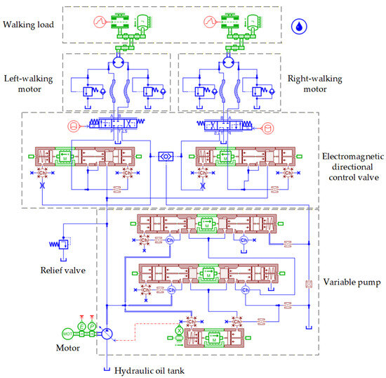
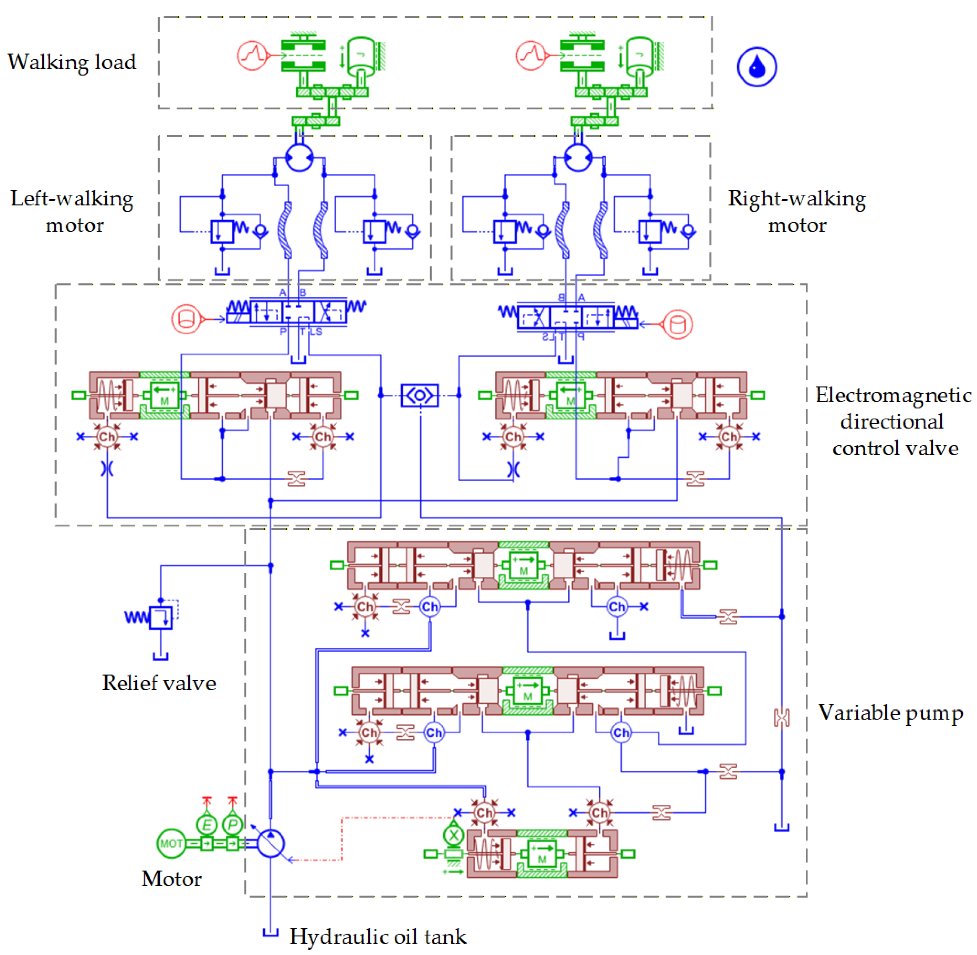
To analyze the dynamic response characteristics and stability of the designed hydraulic powertrain for the motor-driven hydraulic crawler chassis, this study built a complete Simcenter AMESim 2020.1 simulation model of the hydraulic system for the C. oleifera fruit harvester’s motor-driven hydraulic crawler chassis, as shown in Figure 7. In the model, the permanent magnet synchronous motor was equivalent to a controllable speed source. The hydraulic pump adopts a variable pump model whose displacement can be adjusted according to system demand. The hydraulic motors on both sides use identical parameter models, driving the left and right tracks, respectively. The key parameters such as system pressure and flow are monitored via corresponding sensor modules.
Figure 7.
AMESim model of the motor-hydraulic travel system for the C. oleifera fruit harvester.
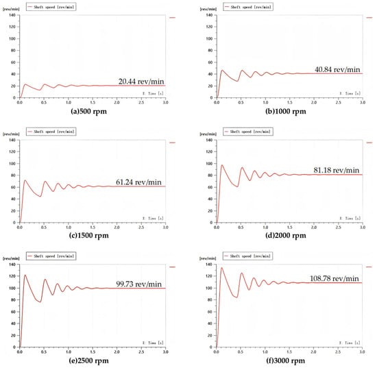
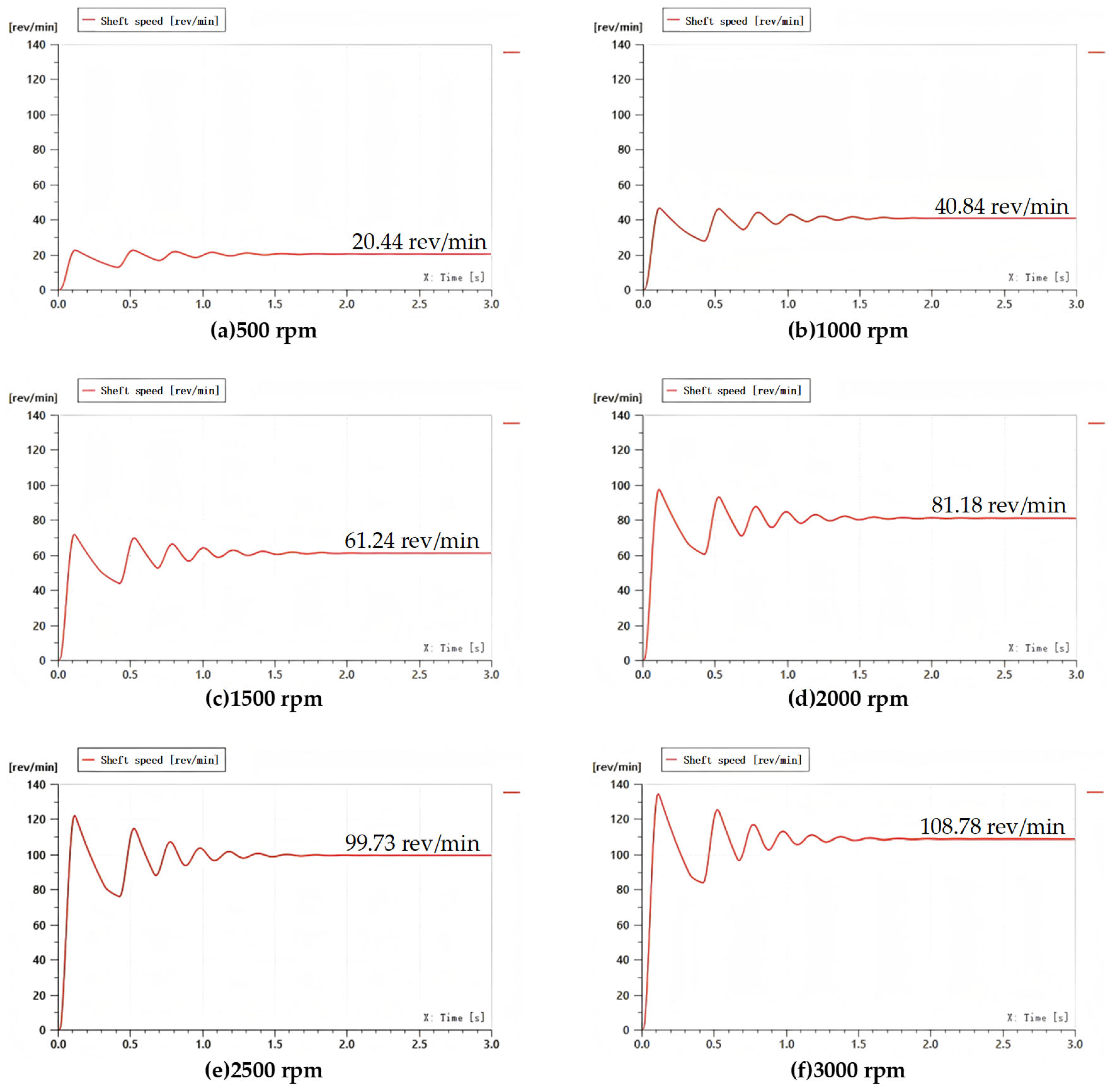
The simulation focused on studying the rotational speed response characteristics of the hydraulic motors under different constant speeds of the drive motor. The motor speed was set to step up to 500 rpm, 1000 rpm, 1500 rpm, 2000 rpm, 2500 rpm, and 3000 rpm, respectively. The output speed changes in the bilateral hydraulic motors were recorded, with results shown in Figure 8.
Figure 8.
Output speed of the hydraulic motor at different rotational speeds in Simcenter AMESim 2020.1 software.
Simulation results show that when the motor speed increases stepwise from 0 to a target value, the hydraulic motor speed exhibits a transient adjustment process lasting approximately 1.5 s. During this period, the speed overshoots and oscillates before gradually converging to a steady-state value. After the system reaches steady state, the hydraulic motor speed fluctuates slightly around the target value. This fluctuation mainly stems from pressure pulsations within the hydraulic system and changes in the volumetric efficiency of the pump and motors. The simulation results indicate that the motor input speed is positively correlated with the steady-state output speed of the hydraulic motor, but the amplitude of the speed fluctuation amplitude increases significantly with higher motor speeds. The fluctuation is most severe at a motor speed of 3000 rpm. This suggests that at higher motor speeds, the system’s pressure and flow pulsations are amplified, which may affect the smoothness of vehicle travel and control accuracy.
Through dynamic simulation analysis, it was clarified that the motor speed is a key factor affecting the stability of the hydraulic drive system. In the high-speed range, although the system can provide higher travel speeds, output stability decreases. Therefore, to balance travel efficiency and smoothness, an optimal operating speed range for the drive motor needs to be determined that balances output capability and system stability. While this simulation was conducted under flat ground conditions, the comprehensive forest vibration harvesting tests (detailed in Section 3.4), which captured the dynamic power response under actual harvesting vibration, serve as the ultimate empirical validation for the system’s robustness under complex coupled loads.
3.2. Motor External Characteristic Calibration Experiment
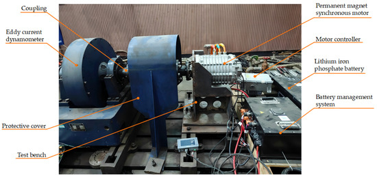
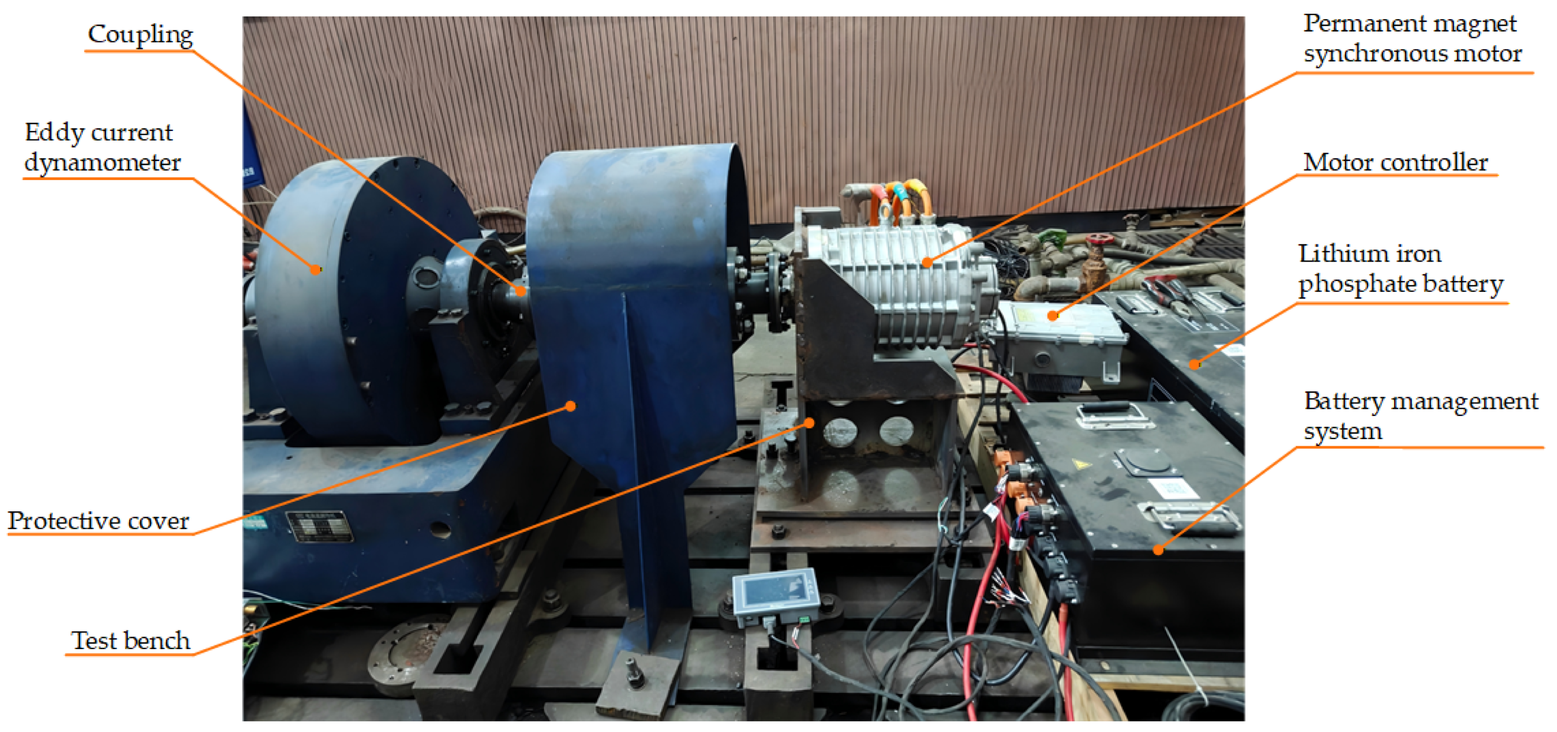
An external characteristic calibration experiment was conducted on the selected PMSM. This ensured the motor’s actual performance matched design expectations and provided precise data for hydraulic system power matching and vehicle control strategy optimization. The experiment aimed to obtain the complete speed-torque-power-efficiency characteristic curve of the motor at rated voltage. This data was then used to determine its maximum output torque, rated power, highest efficiency range, and the specific boundaries of the constant torque and constant power regions. The experimental setup is shown in Figure 9.
Figure 9.
Schematic diagram of the experimental setup.
During the experiment, the motor was directly connected to the dynamometer via a coupling. Under rated voltage, the load torque was gradually increased through the dynamometer control system, causing the motor speed to continuously decrease from no-load state to near stall, thus traversing all operating points of the motor from high to low speed and completely mapping its external characteristic curve.
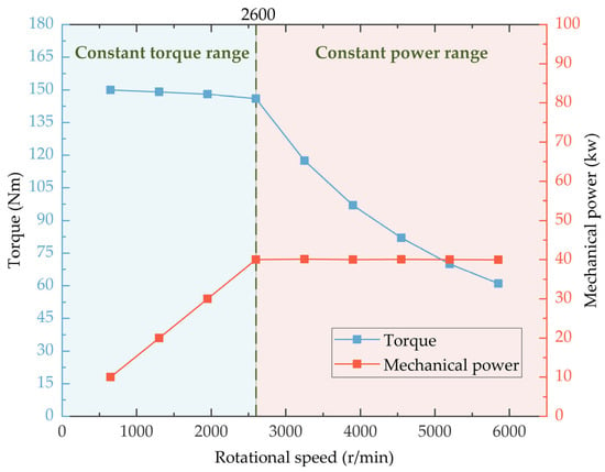
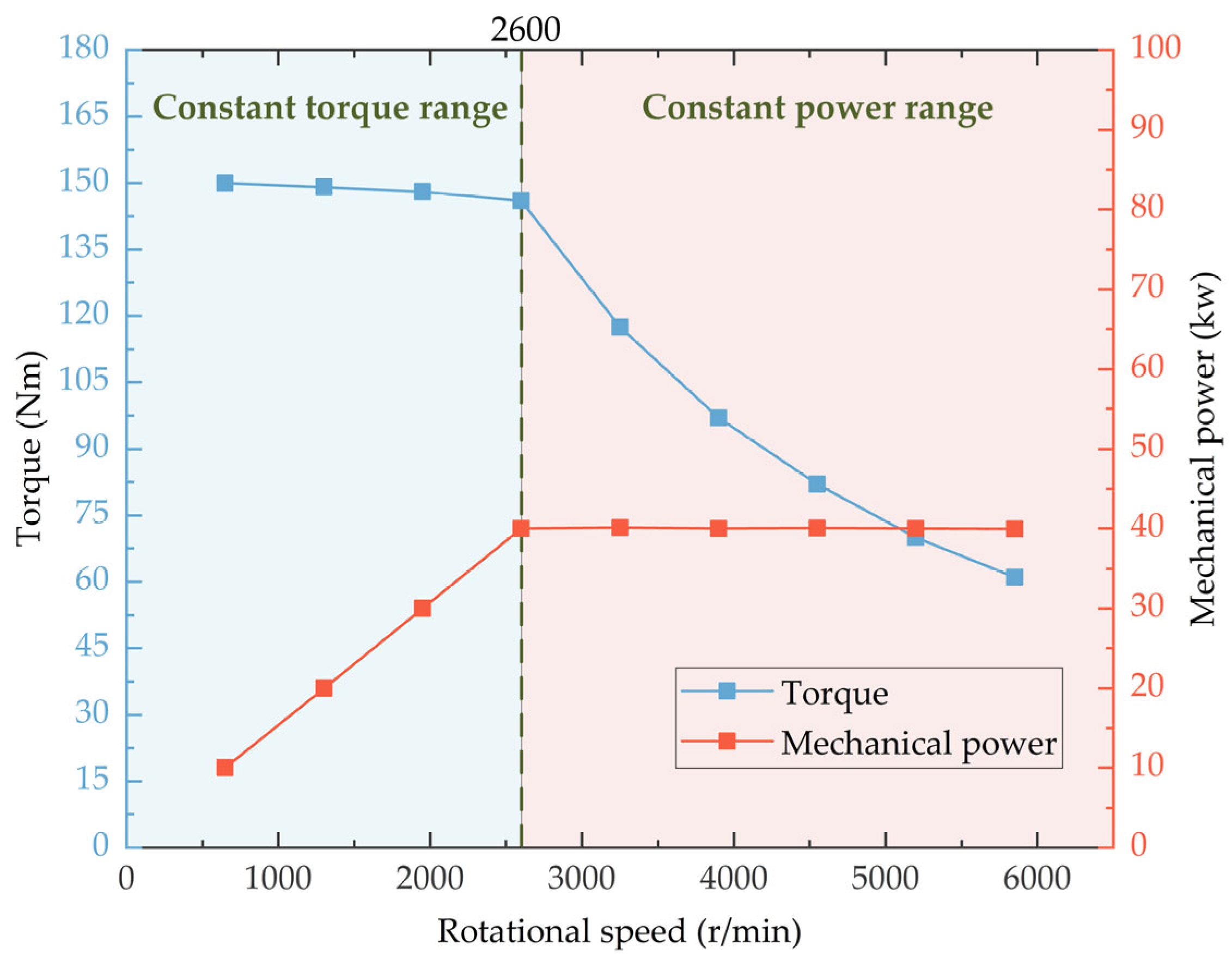
The experiment yielded the motor’s external characteristic curves at different speeds, with results shown in Figure 10. The range of 0–2600 rpm is the motor’s constant torque region. Within this speed range, the motor can output an approximately constant maximum torque. The experiment measured an average output torque of 150.5 N∙m in this region. This result indicates that the motor has good torque output of the capability under low-speed, high-load conditions, meeting the high torque demands of the chassis such as during climbing. The range of 2600–9000 rpm is the motor’s constant power region. In this area, the output voltage remains constant, and the output torque decreases hyperbolically with increasing speed to maintain a basically constant output power. The experiment measured an average output power of approximately 40 kW in this region, higher than the motor’s continuous power rating. It indicates that the motor has sufficient short-term overload (peak power) capability to provide power reserve for vehicle acceleration or overcoming instantaneous high resistance.
Figure 10.
Motor external characteristic curve (with region calibration).
This calibration experiment successfully obtained the complete external characteristic data of the drive motor. The data verifies that the motor’s key performance parameters meet the design selection requirements. The experimental results clearly delineate the motor’s constant torque and constant power regions, providing crucial basis for matching the vehicle’s powertrain system and formulating control strategies. Specifically, when the chassis requires high traction force, such as during start-up or climbing, the motor should be controlled to operate in the constant torque region to fully utilize its maximum torque output capability. Combining with the earlier hydraulic simulation results, at around 2600 rpm, the motor can provide relatively high power while ensuring relatively stable output from the hydraulic system.
3.3. Chassis Performance Testing
To comprehensively verify whether the actual performance of the designed motor-driven hydraulic crawler chassis under preset operating conditions meets the design indicators and to evaluate the safety and operational reliability of the entire machine’s powertrain system, this study conducted multi-scenario field driving tests on the prototype. The tests focused on key performances including level ground straight-line travel, climbing on different road surfaces, maximum gradability, straight-line travel deviation, and steering flexibility. The aim was to comprehensively evaluate the chassis structural design, power matching, and control stability.
3.3.1. Level Ground Travel Speed Test
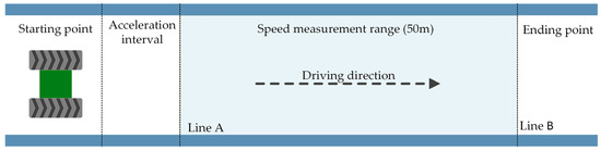
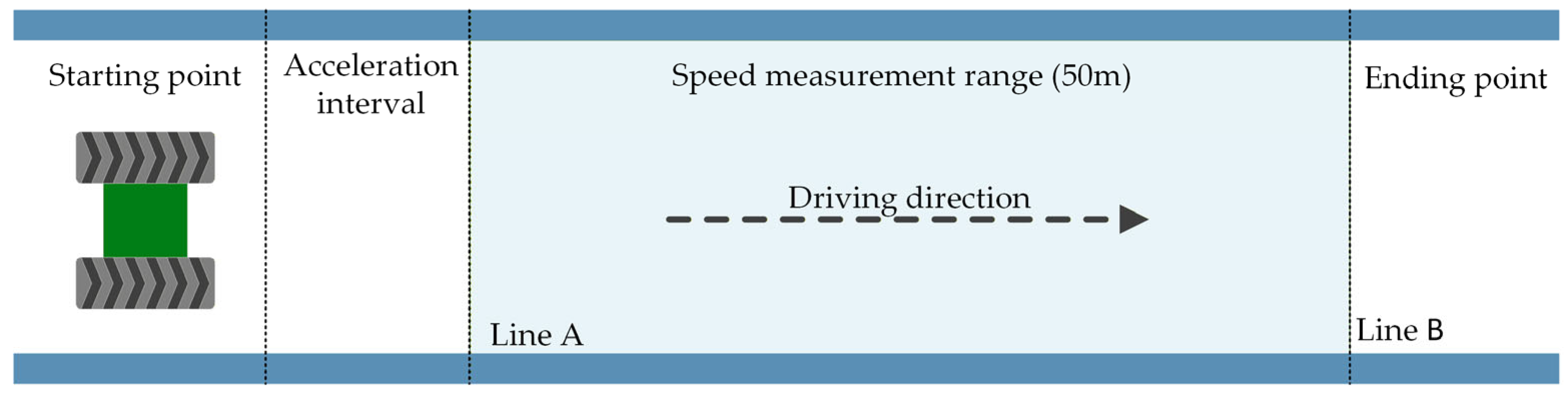
Speed control accuracy and stability during level ground straight-line travel are important indicators for evaluating the basic chassis performance [27]. This test measured the actual travel speed of the prototype on a level, straight road at different preset motor speeds. The experimental site setup is shown in Figure 11.
Figure 11.
Schematic diagram of the level ground travel test.
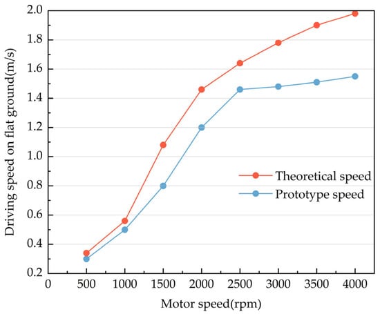
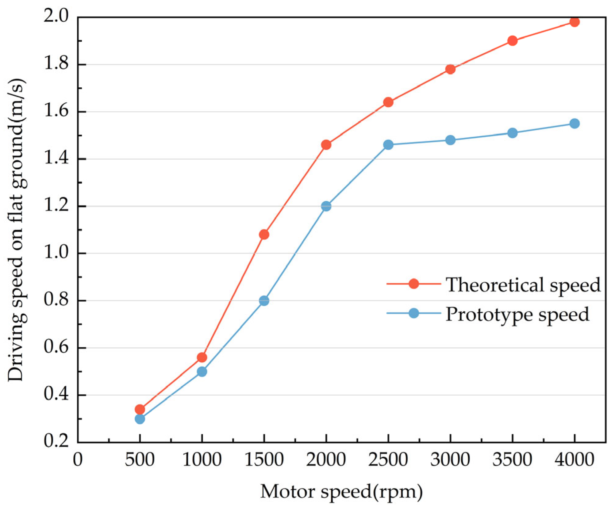
The test was performed on a straight, level 50 m long road section, as shown in Figure 11. To ensure the prototype maintained a constant speed over the measured interval AB, 5 m-long acceleration and deceleration zones were established before point A and after point B, respectively. The motor speed was set to different levels, i.e., 500, 1000, 1500, 2000, 2500, and 3000 rpm, which would drive the prototype to travel uniformly from start point A to end point B. Each speed level was tested three times, recording the travel time to calculate the average speed, which was then compared with theoretical predicted values. The results are shown in Figure 12.
Figure 12.
Comparison of actual and simulated travel speeds at different motor speeds.
When the motor speed was between 0~2500 rpm, the prototype’s actual travel speed trend was consistent with the simulation predictions, but the measured values were slightly lower than the simulated values. This difference mainly stems from mechanical transmission losses and internal leakage in the hydraulic system not fully accounted for in the simulation model. When the motor speed exceeded 2500 rpm, the actual speed increase slowed significantly. This is because when the motor speed exceeds its base speed (approximately 2600 rpm) and enters the constant power region, the output torque decreases. Simultaneously, the hydraulic variable pump may generate protective overflow to maintain stable system pressure. Both factors together limit the linear increase in travel speed.
The test results show that when the motor speed is around 2500 rpm, the hydraulic drive system achieves a better balance between energy efficiency and output stability.
3.3.2. Climbing Test on Different Road Surfaces
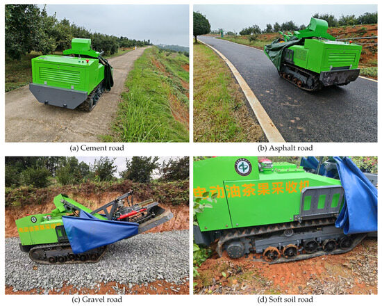
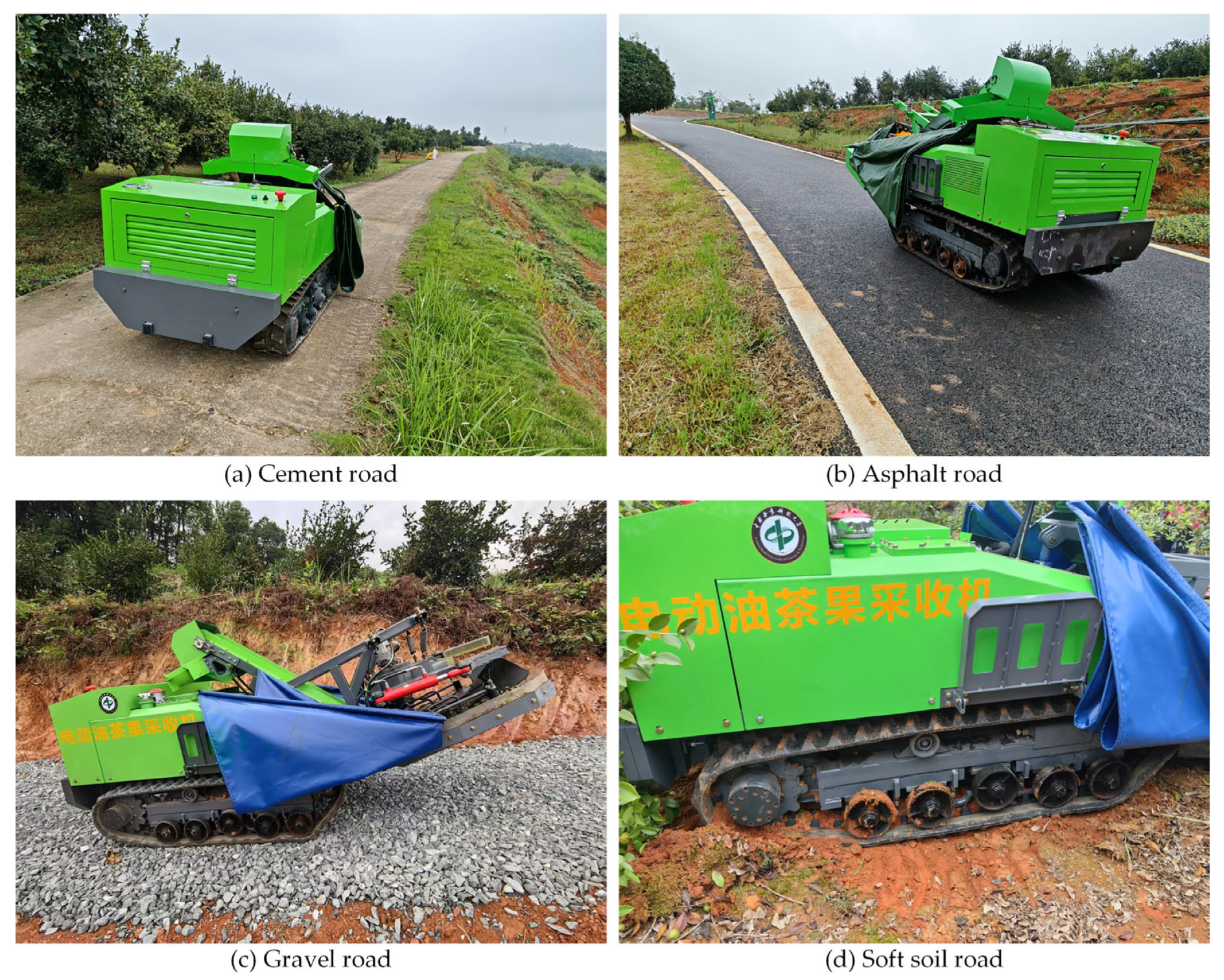
To evaluate the actual trafficability of the chassis and adaptability on typical road surfaces in C. oleifera forest areas, four typical road surfaces were selected: concrete, asphalt, gravel, and soft soil. The road conditions are shown in Figure 13. The prototype underwent climbing tests on a 15° slope. The test results are shown in Table 4.
Figure 13.
The prototype on four types of terrain.
Table 4.
Prototype travel on a 15° slope across different road surfaces.
In all tests, the prototype smoothly completed the climb without slipping or instability. The travel speed decreased slightly with lower road surface adhesion coefficients, which aligns with theoretical expectations. On the soft soil surface with the weakest adhesion, the average speed remained at 0.77 m∙s−1, fully meeting the practical requirements for hilly and mountainous operations. This proves that the crawler travel mechanism and hydraulic drive system have good adaptability to different ground conditions.
3.3.3. Maximum Climbing Test
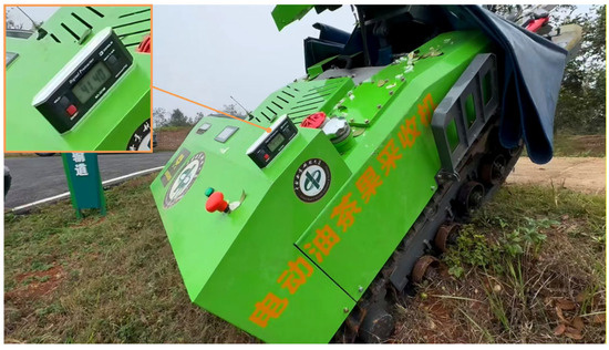
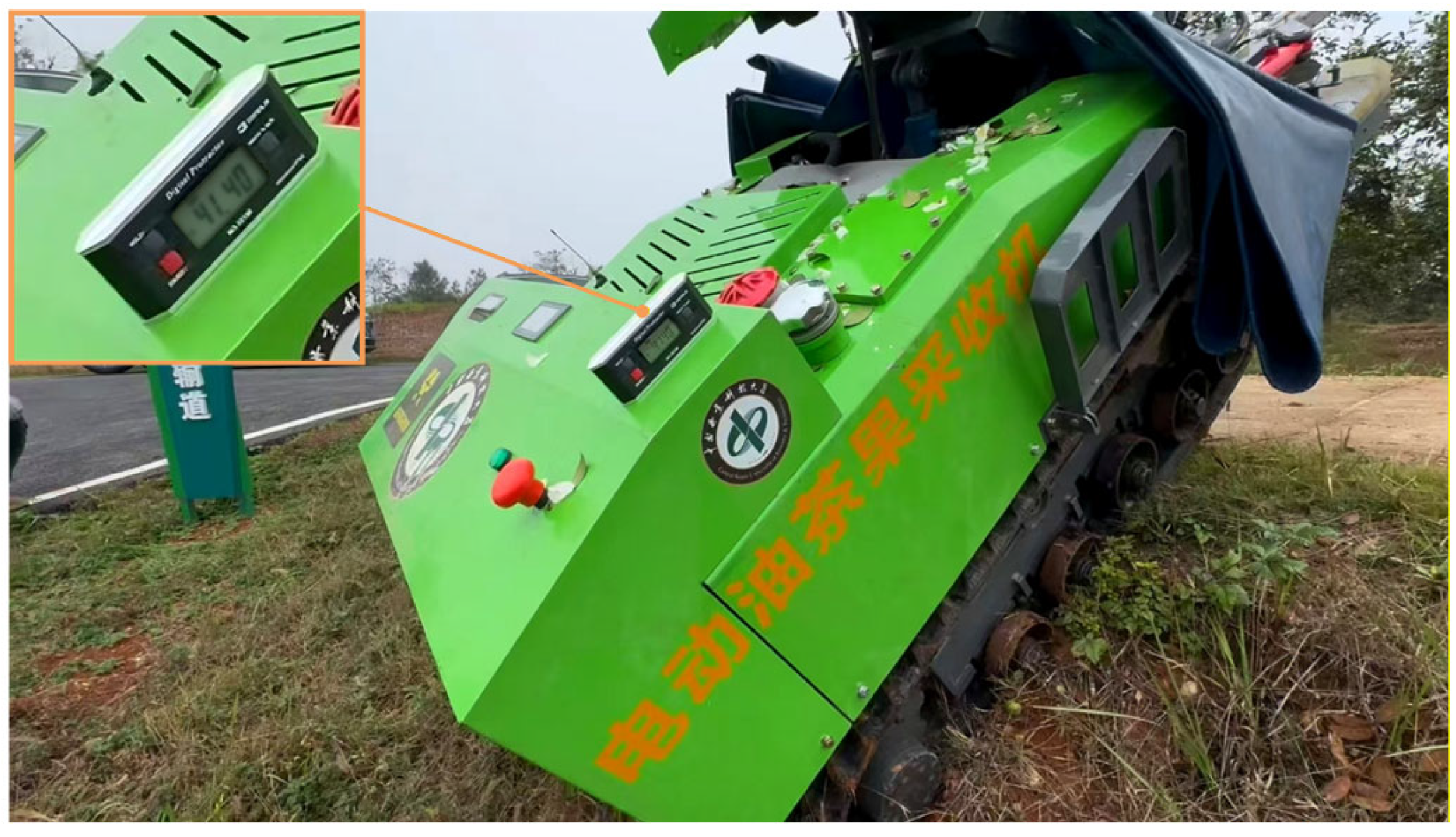
The ultimate climbing ability is a key indicator for measuring the power and trafficability of mountain agricultural machinery. The test was conducted on a dry, solid soil slope. Specifically, the test site was located in a Camellia oleifera orchard in Wangcheng District, Changsha, on a sunny day with a slope length of 4 m. The soil was identified as compacted red clay loam with a measured moisture content of approximately 16.5% and a cone index (CI) of about 1200 kPa. As shown in Figure 14, the prototype successfully ascended an extreme slope of 41.4°. The test was repeated three times, and the limiting criterion was defined as excessive track slip rather than motor stall. This value far exceeds the design target of 25°. It fully verifies the ample torque of the motor-hydraulic powertrain and the excellent adhesion of the crawler chassis, demonstrating its capability to handle most steep slopes in hilly terrain.
Figure 14.
Testing site for maximum gradeability of the chassis.
3.3.4. Travel Deviation Test
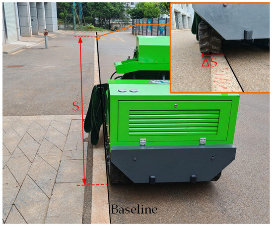
The straight-line travel deviation is a key indicator for evaluating the synchronization control accuracy of the bilateral hydraulic motors and the mechanical symmetry of the chassis [28]. The test was conducted on a 50 m level, straight ground with no slope (see Figure 15). The prototype traveled at a constant speed at different motor speeds along a preset reference line. Upon completion, the vertical deviation distance between the left track and the reference line was measured. Each speed was tested three times. The deviation was calculated according to Equation (24).
where is the deviation; is the deviation distance, m; is the test distance, 50 m.
Figure 15.
Field setup for the deviation test of the motor-driven hydraulic crawler chassis prototype.
The test results are shown in Table 5. The data indicate that the deviation increases slightly with increasing motor speed, primarily due to the increased asymmetry in hydraulic system characteristics at higher flow rates. However, at all tested speeds, the deviation was strictly less than 2%, meeting the design requirements. This proves that the hydraulic system and control system ensure good straight-line travel stability.
Table 5.
Prototype deviation test results.
3.3.5. Steering Performance Test
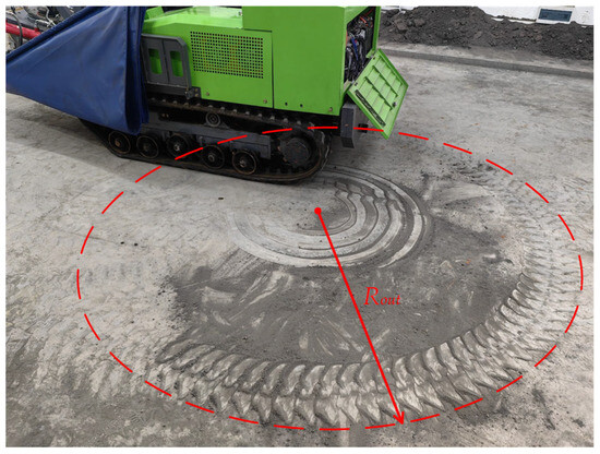
Steering flexibility directly affects the harvester’s operational efficiency among densely planted trees [29]. Based on the differential steering principle of independently driven left and right tracks, the minimum turning radius for the prototype to achieve a 180° turn was tested. During the test, one track was kept stationary while the other advanced. The rolling track radius formed by the outer track on the ground was measured. The test site is shown in Figure 16. All test results are shown in Table 6.
Figure 16.
Field test of single-side steering.
Table 6.
Steering performance test results.
At different drive speeds, the measured outer track turning radius ranged from 1.19 m to 1.23 m, with an average turning radius of 1.22 m. At this point, the minimum turning radius can be obtained by Equation (25).
After calculation, the minimum turning radius is 0.72 m, slightly larger than the theoretical minimum turning radius of 0.5 m. This difference mainly stems from the ideal assumptions of the theoretical model (pure rolling, complete braking) versus the differences in actual conditions, such as unavoidable track slip during steering. The similar turning radii at different speeds prove that the theoretical minimum turning radius is only related to the track gauge . However, the actual turning radius is also significantly influenced by soil shear characteristics and track slip. Therefore, the reported values are specific to the tested ground conditions. The average steering time was 4.9 s, proving that when is 0, the steering time is inversely proportional to the speed of the active side track . In the test data, the steering time decreased from 8.87 s (500 rpm) to 4.39 s (3000 rpm), a trend highly consistent with theoretical predictions.
In summary, the steering performance test results effectively corroborate the steering radius and steering time mathematical models derived from kinematic analysis. The tests show that the designed motor-hydraulic drive system can achieve precise and rapid differential steering control. The chassis average turning radius is 0.72 m, and the steering process is smooth and efficient, thus fully meeting the mobility requirements for operation within the narrow spaces of C. oleifera forests.
3.3.6. Chassis Noise Test
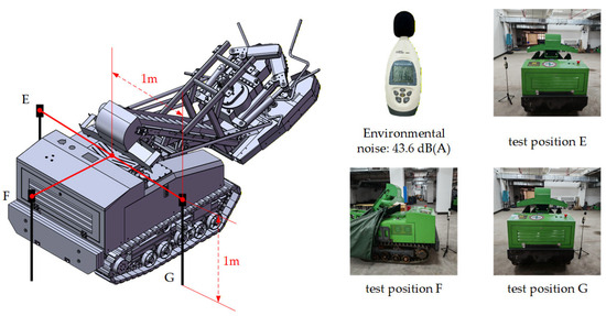
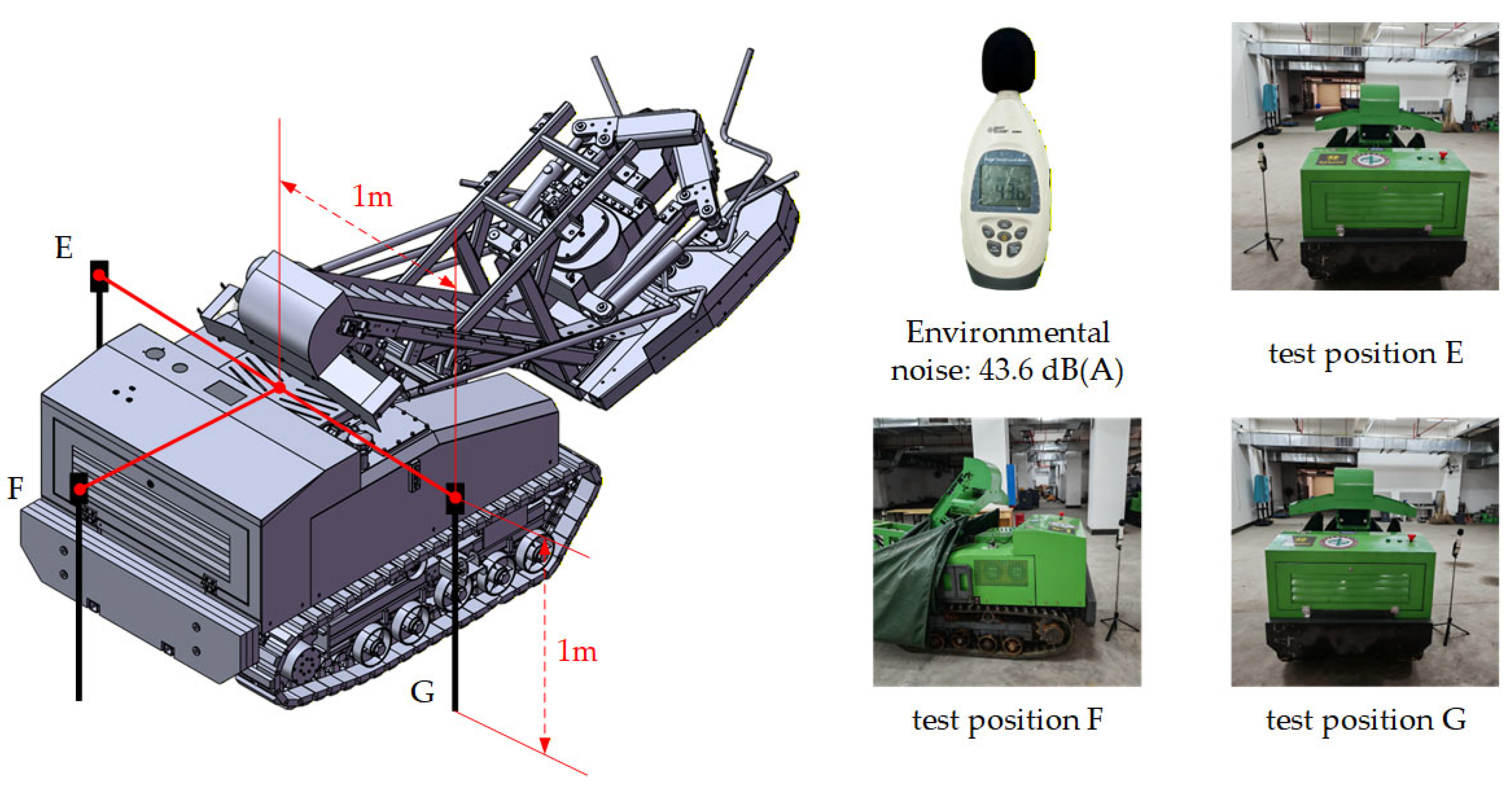
This study carried out an acoustic performance test on the prototype to quantitatively evaluate the in-operation noise level of the motor-driven hydraulic crawler chassis and to verify its low-noise advantage compared to traditional internal combustion engine machinery. The noise test aimed to obtain sound pressure level data of the chassis under key operating conditions, providing empirical evidence for “green, low-interference” mountainous operations. The test site was selected as an open and flat ground, and a standard Class 1 precision integrating sound level meter was used for measurement. Figure 17 shows the measurement point layout in standby mode, with the sound level meter placed symmetrically on both sides and at the rear of the prototype. Specifically, the sound level meter was positioned 1 m from the motor center and 1 m above the ground. Before and after the test, the ambient background noise was measured and recorded. For the traveling state, the highest noise level was recorded when the chassis passed the sound level meter at full speed in a straight line. During the test, the noise levels of the chassis under two conditions were measured at motor speeds of 500, 1000, 1500, 2000, 2500, and 3000 rpm. Each operating condition was tested three times, and the average value was taken as the final result.
Figure 17.
Schematic diagram of noise test in standby mode.
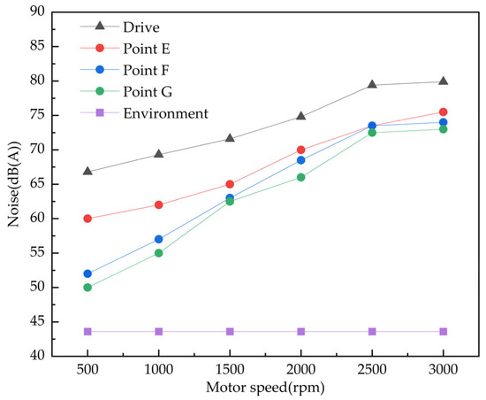
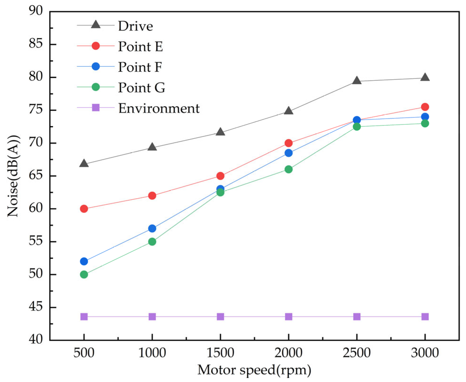
The average background noise during the testing period was 43.2 dB(A). The noise test results of the prototype under different conditions are shown in Figure 18.
Figure 18.
The noise test results of the prototype.
As can be seen from the figure, when the prototype is in standby mode, the noise at test position E is higher than that at the other two positions. This is attributed to the proximity of position E to the cooling fan, which operates to dissipate heat from the motor. The noise levels recorded at the other two positions are comparable. However, at position G, the level is slightly lower than at position F, a difference attributable to the presence of the hydraulic oil tank. When the prototype operates in low-speed travel mode, the primary noise source is the traveling mechanism, such as friction between the rubber track and the ground. However, when the motor speed of the prototype exceeds 2000 rpm, the motor becomes the dominant source of noise. At this stage, the sound primarily originates from the motor’s own rotation and high-frequency vibrations transmitted through the coupling and the hydraulic pump.
Under all tested conditions, the operational noise of the prototype was significantly lower than that of traditional diesel-powered agricultural machinery of the same power class (typically 85–100 dB(A)) [30]. Even at the maximum tested speed of 3000 rpm under full-load travel, the measured noise level is only 79.4 dB(A), which is below the occupational Exposure limit values (LEX) of 87 dB(A) [31]. It is worth noting that due to the logarithmic nature of the decibel scale, a reduction of >6 dB(A) represents approximately a 50% decrease in subjective loudness, significantly improving operator comfort. This indicates that the prototype does not cause significant acoustic disturbance to the operator or the surrounding environment, aligning with the development philosophy of green agricultural machinery and demonstrating the substantial advantage of the motor-hydraulic drive system in noise reduction at the source.
3.4. Dynamic Power Characteristic Test Under Vibration Harvesting Condition
Test objective: Unlike conventional transport vehicles, the prime mover (central drive motor) of this harvester must simultaneously supply power for both the chassis drive and the active vibration harvesting mechanism. The load characteristics during harvesting are not static but highly dynamic. The objective of this test is to experimentally characterize the dynamic power consumption profile and load fluctuation magnitude of the drive motor under actual vibration harvesting conditions using the onboard monitoring system. This verifies whether the selected motor has sufficient dynamic response capability to handle the complex superimposed loads.
The field test was conducted in a Camellia oleifera plantation to characterize the dynamic power consumption under realistic harvesting conditions. The prototype was positioned adjacent to a selected tree, and its harvesting head was engaged to grasp the trunk. The experimental site is shown in Figure 19. This setup allowed the measurement of the motor’s power profile during an actual vibration harvesting operation, isolating the load of the harvesting mechanism from that of chassis propulsion. Data acquisition was performed using the integrated Vehicle Control Unit (VCU) monitoring system rather than external sensors. Via the high-speed CAN bus interface, key operational parameters of the central motor controller—including DC bus voltage , bus current , and actual motor speed—were recorded synchronously at a sampling rate of 60 Hz. The real-time input power to the motor controller was then computed as .
Figure 19.
Site diagram of vibration harvesting test.
The experimental procedure was conducted as follows. First, the central electric motor was started and brought to its rated operating speed via a VCU command, while initial background idling power data was recorded. The vibration harvesting operation was then triggered manually using the handheld remote controller. The controller issued a command to open the hydraulic control valve corresponding to the vibration mechanism. This allowed pressurized oil to drive the eccentric hydraulic motor within the harvesting head, generating forced vibration. The harvesting head executed a predefined sequence comprising four vibration bursts, each lasting 3 s. The intervals between bursts were set deliberately: 0.5 s between the first and second bursts, a deliberate 2.5 s pause (stationary interval) between the second and third bursts, and again 0.5 s between the third and fourth bursts, resulting in a total cycle duration of 20 s. Throughout the entire 20 s cycle, key parameters—including DC bus voltage, current, calculated input power, and motor speed—were continuously recorded via the VCU system at a sampling rate of 60 Hz to capture the dynamic transients associated with each vibration burst and interval. To ensure statistical reliability, the entire test cycle was repeated three times.
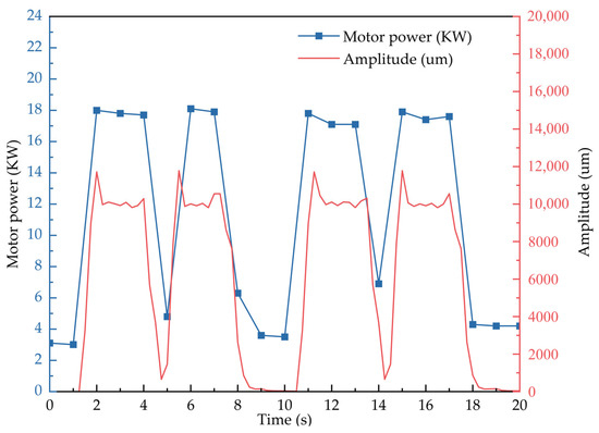
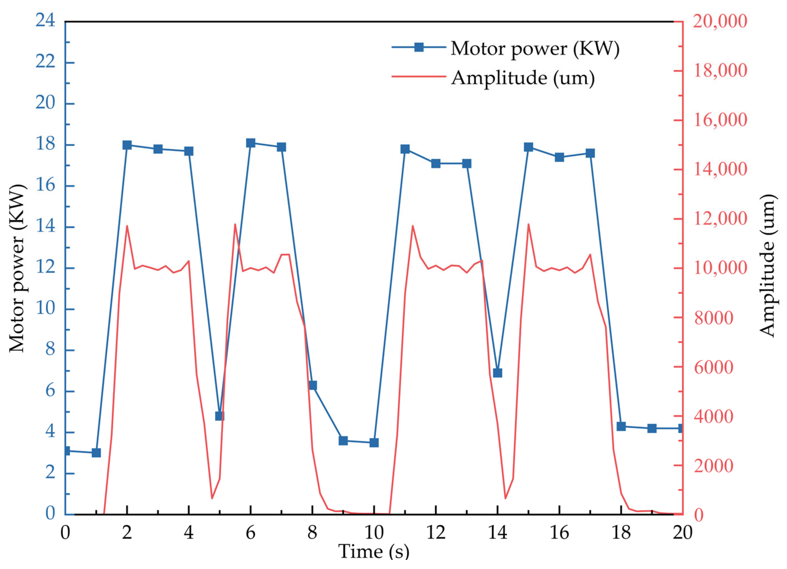
The Vibration harvesting test result chart is shown in Figure 20. The test results clearly delineate the power profile during intermittent vibration harvesting. Throughout the stationary intervals, the system maintained a steady background power of approximately 3.5 kW. Upon activation of each 3 s vibration burst, the motor input power surged immediately, reaching an average power of 17.67 kW during vibration phases and a peak value of 18.1 kW. The power curve exhibited a distinct square-wave pattern, precisely synchronizing with the on/off commands of the hydraulic valve and accurately reflecting the predefined sequence of vibration and pause intervals.
Figure 20.
Vibration harvesting test result chart.
The recorded data indicate that the selected PMSM—rated at 45 kW peak power and 23 kW continuous power—operated well within its performance envelope. The observed maximum power of 18.1 kW remained below both its continuous and peak ratings, confirming that the motor possesses ample reserve to handle the combined loads of chassis propulsion and harvesting, thereby validating the initial power-matching calculations in Section 2.5.3. The motor-controller system demonstrated excellent dynamic response, with power output closely tracking the on-off load profile and showing minimal lag during both activation and cessation of vibration bursts. This rapid and stable response is essential for maintaining consistent vibration amplitude and frequency at the harvesting head, which directly influences fruit removal efficacy and minimizes tree damage. Moreover, the pronounced power fluctuation—from a 3.5 kW baseline to an 18.1 kW peak within seconds—underscores the dynamic nature of the operational load. This imposes specific demands on the supporting subsystems: the battery pack and DC bus must be capable of delivering such pulsed currents without significant voltage sag, and the hydraulic variable pump must respond swiftly to maintain stable pressure for the vibration motor.
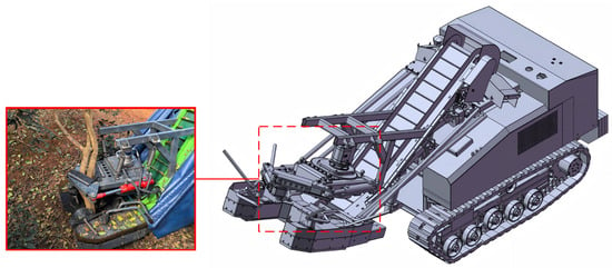
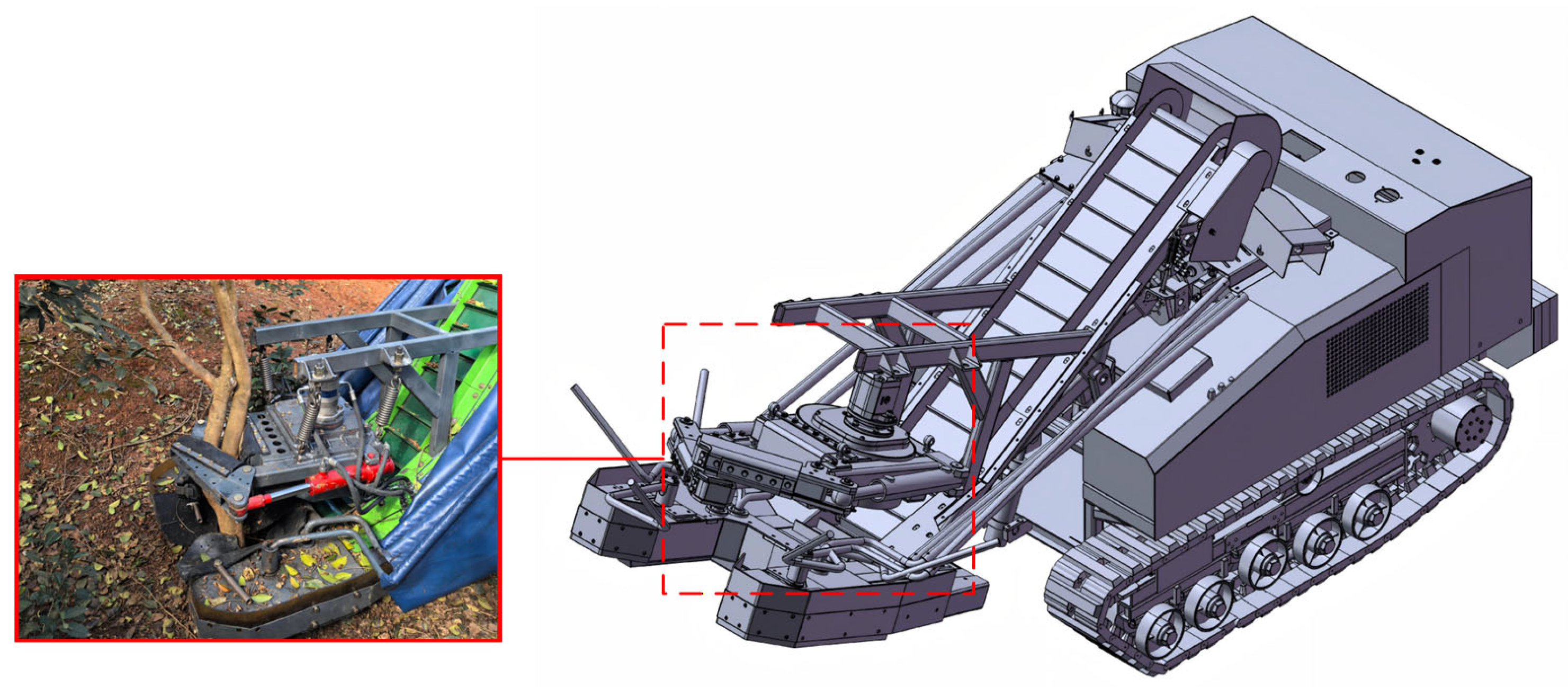
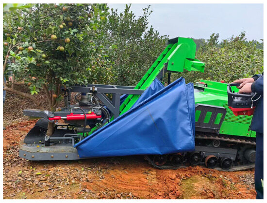
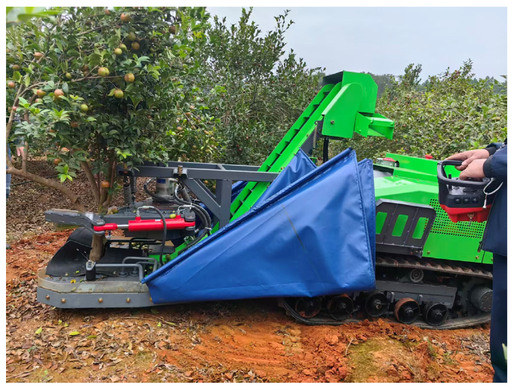
The stable operation observed throughout the test confirms that the current design of the power and hydraulic systems adequately accommodates these dynamic requirements. Field tests further confirmed the machine’s operational efficacy. The field test site for Camellia oleifera fruit harvesting performance is shown in Figure 21. The prototype achieved an effective harvesting efficiency of ≥30 trees/h with an average fruit removal rate of ≥90%. Regarding damage control, the clamping mechanism caused only superficial marks (approximately 25 cm2) on the bark without permanent phloem damage. Notably, the flower drop rate was controlled to be <7%, which is critical for ensuring the subsequent year’s yield given the synchronous flowering and fruiting characteristic of Camellia oleifera. These data confirm that the prototype functions effectively as a “combine” harvester, integrating robust chassis mobility with efficient harvesting capabilities.
Figure 21.
Field test site for Camellia oleifera fruit harvesting performance.
4. Conclusions
This study successfully designed and tested a motor-driven hydraulic crawler chassis for C. oleifera fruit harvesting, effectively addressing the poor terrain adaptability of traditional agricultural machinery and its associated environmental impact in the complex terrain of hilly and mountainous areas. Through theoretical design of the overall machine scheme, simulation analysis, and experimental prototype verification, the following conclusions were drawn.
(1) The proposed motor-driven hydraulic crawler chassis solution effectively eliminates emissions and ensures low-noise operation by using an electric motor as the power source. The hydraulic transmission system overcomes the layout rigidity of mechanical drives, enabling flexible power distribution, stepless speed regulation, and overload protection.
(2) Through kinematic modeling and AMESim simulations, the component parameters were matched to ensure dynamic stability under varying motor speeds. Experimental calibration further defined the optimal operating range of the motor, balancing efficiency and output capability for the hybrid powertrain.
(3) Field tests verified the robust performance of chassis, achieving a maximum speed greater than 1.5 m∙s−1, a climbing angle of 41.4° (exceeding the 25° design target), and a turning radius of 0.72 m. Notably, the maximum operational noise is only 79.4 dB(A). Compared with traditional internal combustion engine agricultural machinery (typically 85–100 dB(A)), this design reduces noise levels by approximately 5–20 dB(A), significantly improving the operating environment. The chassis also demonstrated excellent reliability across diverse terrains, including soft soil and gravel.
(4) Dynamic power characteristic tests confirmed that the selected 45 kW permanent magnet synchronous motor provides an ample power reserve. The system maintained a rapid and stable response to square-wave loads (peaking at 18.1 kW) caused by the vibration mechanism, ensuring consistent harvesting frequency without compromising battery stability.
In summary, the motor-driven hydraulic crawler chassis designed in this study for C. oleifera fruit harvesting scenarios in hilly and mountainous areas not only provides a practical and feasible technical solution but also offers valuable reference for the electrification upgrade and intelligent transformation of similar agricultural and forestry operating equipment. Future research will focus on further optimization of overall vehicle energy consumption, deep integration of intelligent control strategies, and durability testing of key components. In addition, preliminary economic analysis indicates that despite higher initial costs, the low operational expenses and high efficiency (10 times that of manual labor) ensure a rapid return on investment, making the system economically viable for large-scale promotion. These efforts aim to continuously improve its comprehensive performance and market competitiveness.
Author Contributions
Conceptualization, F.C. and K.L.; methodology, Y.Z. and F.C.; software, Y.Z.; validation, Y.Z., F.C. and K.L.; formal analysis, B.W.; investigation, Y.Z. and F.C.; resources, K.L.; data curation, B.W.; writing—original draft preparation, Y.Z. and F.C.; writing—review and editing, Y.Z. and F.C.; visualization, Y.Z.; supervision, F.C. and K.L.; project administration, K.L.; funding acquisition, K.L. All authors have read and agreed to the published version of the manuscript.
Funding
This research was funded by the National Key Research and Development Program of China (No. 2022YFD2202103).
Institutional Review Board Statement
Not applicable.
Informed Consent Statement
Not applicable.
Data Availability Statement
The data presented in this study are available on request from the corresponding author.
Acknowledgments
The authors would like to thank the research team members for their contribtions to this work.
Conflicts of Interest
The authors declare no conflicts of interest.
References
- Liu, R.C.; Xiao, Z.Y.; Hashem, A.; Abd_Allah, E.F.; Wu, Q.S. Mycorrhizal fungal diversity and its relationship with soil properties in Camellia oleifera. Agriculture 2021, 11, 470. [Google Scholar] [CrossRef] [Scilit]
- Yan, F.; Li, X.; Huang, G.; Li, X. Camellia Oleifera Fresh Fruit Harvesting in China. In Proceedings of the 2020 5th International Conference on Mechanical, Control and Computer Engineering (ICMCCE), Harbin, China, 25–27 December 2020; IEEE: New York, NY, USA, 2020; pp. 699–702. [Google Scholar] [CrossRef] [Scilit]
- Zhu, X.; Chen, F.; Zheng, Y.; Chen, C.; Peng, X. Detection of Camellia oleifera fruit maturity in orchards based on modified lightweight YOLO. Comput. Electron. Agric. 2024, 226, 109471. [Google Scholar] [CrossRef] [Scilit]
- Wang, L.; Zhang, R.; Zhang, L.; Yi, T.; Zhang, D.; Zhu, A. Research on Individual Tree Canopy Segmentation of Camellia oleifera Based on a UAV-LiDAR System. Agriculture 2024, 14, 364. [Google Scholar] [CrossRef] [Scilit]
- Liu, C.X.; Chen, L.S.; Tang, W.; Peng, S.F.; Li, M.Q.; Deng, N.; Chen, Y.Z. Predicting Potential Distribution and Evaluating Suitable Soil Condition of Oil Tea Camellia in China. Forests 2018, 9, 487. [Google Scholar] [CrossRef] [Scilit]
- Luan, F.; Zeng, J.S.; Yang, Y.; He, X.R.; Wang, B.J.; Gao, Y.B.; Zeng, N. Recent advances in Camellia oleifera Abel: A review of nutritional constituents, biofunctional properties, and potential industrial applications. J. Funct. Foods 2020, 75, 104242. [Google Scholar] [CrossRef] [Scilit]
- Liu, S.J.; Chen, T.T.; Ye, D. Prediction of distributional patterns of four major Camellia oilseed species in China under climate and land use changes. Ecol. Indic. 2023, 155, 110996. [Google Scholar] [CrossRef] [Scilit]
- Manzo, C.; Maharlooei, M.; Ehsani, R.; Ferguson, L. Development and Evaluation of a Continuous Canopy Shaker for California Table Olives. In Proceedings of the 2023 ASABE Annual International Meeting, Omaha, NE, USA, 9–12 July 2023. Paper No. 2301417. [Google Scholar] [CrossRef] [Scilit]
- Homayouni, T.; Maharlooei, M.; Toudeshki, A.; Ferguson, L.; Ehsani, R. Simultaneous Trunk and Canopy Shaking Improves Table Olive Harvester Efficiency versus Trunk Shaking Alone. Horticulturae 2023, 9, 640. [Google Scholar] [CrossRef] [Scilit]
- Du, X.; Chen, K.; Ma, Z.; Wu, C.; Zhang, G. Design, construction, and evaluation of a three-dimensional vibratory harvester for tree fruit. Appl. Eng. Agric. 2020, 36, 221–231. [Google Scholar] [CrossRef] [Scilit]
- Ma, R.; Homayouni, T.; Toudeshki, A.; Ehsani, R.; Zhang, X. An Experimental Study and Mathematical Modeling of Vibration Transfer in Pistachio Trees Using an Inertia-Type Trunk Shaker and Field-Adapted Wireless Sensors. Shock Vib. 2022, 2022, 9966848. [Google Scholar] [CrossRef] [Scilit]
- Leone, A.; Romaniello, R.; Tamborrino, A.; Catalano, P.; Peri, G. Identification of vibration frequency, acceleration, and duration for efficient olive harvesting using a trunk shaker. Trans. ASABE 2015, 58, 19–26. [Google Scholar] [CrossRef] [Scilit]
- Zhou, J.; He, L.; Zhang, Q.; Du, X.; Chen, D.; Karkee, M. Evaluation of the influence of shaking frequency and duration in mechanical harvesting of sweet cherry. Appl. Eng. Agric. 2013, 29, 607–612. [Google Scholar] [CrossRef] [Scilit]
- Rosa, U.; Rosenstock, T.; Choi, H.; Pursell, D.; Gliever, C.; Brown, P.; Upadhyaya, S. Design and evaluation of a yield monitoring system for pistachios. Trans. ASABE 2011, 54, 1555–1567. [Google Scholar] [CrossRef] [Scilit]
- Pu, Y.; Toudeshki, A.; Ehsani, R.; Yang, F. Design and evaluation of a two-section canopy shaker with variable frequency for mechanical harvesting of citrus. Int. J. Agric. Biol. Eng. 2018, 11, 77–87. [Google Scholar] [CrossRef] [Scilit]
- Bentaher, H.; Haddar, M.; Fakhfakh, T.; Mâalej, A. Finite elements modeling of olive tree mechanical harvesting using different shakers. Trees 2013, 27, 1537–1545. [Google Scholar] [CrossRef] [Scilit]
- Hu, K.; Zhang, W. Design and Simulation for Driving System and Steering System of Hydraulic Chassis of Rice Transplanter. Adv. Mech. Eng. 2018, 10, 1687814018808901. [Google Scholar] [CrossRef] [Scilit]
- Yang, J.; Qin, X.; Lei, J.; Lu, L.; Zhang, J.; Wang, Z. Design and Experiment of a Crawler-Type Harvester for Red Cluster Peppers in Hilly and Mountainous Regions. Agriculture 2024, 14, 1742. [Google Scholar] [CrossRef] [Scilit]
- Xiao, M.; Zhao, Y.; Wang, H.; Xu, X.; Bartos, P.; Zhu, Y. Design and Test of Hydraulic Driving System for Undercarriage of Paddy Field Weeder. Agriculture 2024, 14, 595. [Google Scholar] [CrossRef] [Scilit]
- Wen, C.K.; Ren, W.; Zhu, Q.Z.; Zhao, C.J.; Luo, Z.H.; Zhang, S.L.; Xie, B.; Meng, Z.J. Reducing Operation Emissions and Improving Work Efficiency Using a Pure Electric Wheel Drive Tractor. Engineering 2024, 37, 157–167. [Google Scholar] [CrossRef] [Scilit]
- Fu, Y.; Liu, Z.; Jiang, Y.; Leng, Y.; Tang, J.; Wang, R.; Lv, X. Simulation and Experiment of the Smoothness Performance of an Electric Four-Wheeled Chassis in Hilly and Mountainous Areas. Sustainability 2023, 15, 16868. [Google Scholar] [CrossRef] [Scilit]
- Zhou, L.; Hu, C.; Chen, Y.; Guo, P.; Zhang, L.; Liu, J.; Chen, Y. Research and Experiment on Cruise Control of a Self-Propelled Electric Sprayer Chassis. Agriculture 2024, 14, 902. [Google Scholar] [CrossRef] [Scilit]
- Xie, B.; Wang, X.; Wu, C.; Wen, C.; Zhang, X.; Zhao, X. Design and Hardware-in-the-Loop Test of a Coupled Drive System for Electric Tractor. Biosyst. Eng. 2022, 216, 165–185. [Google Scholar] [CrossRef] [Scilit]
- He, S.W.; Shen, Y.; Zhang, Y.F.; Liu, H. Development and Evaluation of 4WSS Electric-Driven Chassis for High-Clearance Sprayer. Front. Plant Sci. 2023, 14, 1258744. [Google Scholar] [CrossRef] [Scilit]
- Ding, R.K.; Qi, X.Y.; Meng, X.P.; Chen, X.W.; Zhang, L.; Mei, Y.X.; Li, A.Z.; Ye, Q. A Review on the Chassis Configurations and Key Technologies of Agricultural Robots. Agriculture 2025, 15, 2379. [Google Scholar] [CrossRef] [Scilit]
- Mou, X.B.; Luo, Q.; Ma, G.J.; Wan, F.X.; He, C.C.; Yue, Y.J.; Yue, Y.M.; Huang, X.P. Simulation Analysis and Testing of Tracked Universal Chassis Passability in Hilly Mountainous Orchards. Agriculture 2023, 13, 1458. [Google Scholar] [CrossRef] [Scilit]
- Li, S.C.; Xu, H.Z.; Ji, Y.H.; Cao, R.Y.; Zhang, M.; Li, H. Development of a following agricultural machinery automatic navigation system. Comput. Electron. Agric. 2019, 160, 145–156. [Google Scholar] [CrossRef] [Scilit]
- Yue, B.B.; Zhang, Z.G.; Zhang, W.Y.; Luo, X.W.; Zhang, G.C.; Huang, H.X.; Wu, X.L.; Bao, K.Y.; Peng, M.D. Design of an Automatic Navigation and Operation System for a Crawler-Based Orchard Sprayer Using GNSS Positioning. Agronomy 2024, 14, 271. [Google Scholar] [CrossRef] [Scilit]
- Wang, Y.X.; Jin, C.Q.; Yang, T.X.; Wang, T.G.; Ni, Y.L. Analysis and Experimental Investigation of Steering Kinematics of Driven Steering Crawler Harvester Chassis. Agriculture 2024, 14, 65. [Google Scholar] [CrossRef] [Scilit]
- Bilski, B. Exposure to infrasonic noise in agriculture. Ann. Agric. Environ. Med. 2017, 24, 86–89. [Google Scholar] [CrossRef] [Scilit]
- Di Stefano, V.; Cecchini, M.; Riccioni, S.; Di Domenico, G.; Bianchini, L. Exposure to Noise from Agricultural Machinery: Risk Assessment of Agricultural Workers in Italy. AgriEngineering 2025, 7, 87. [Google Scholar] [CrossRef] [Scilit]

Disclaimer/Publisher’s Note: The statements, opinions and data contained in all publications are solely those of the individual author(s) and contributor(s) and not of MDPI and/or the editor(s). MDPI and/or the editor(s) disclaim responsibility for any injury to people or property resulting from any ideas, methods, instructions or products referred to in the content. |
© 2026 by the authors. Licensee MDPI, Basel, Switzerland. This article is an open access article distributed under the terms and conditions of the Creative Commons Attribution (CC BY) license.