


Abstract
In view of the current situation that there exists big impact and friction between the gripper and the guide in the weft insertion mode of the existing gripper loom, this paper puts forward the idea of the electromagnetic-driven two-way weft insertion on gripper in order to improve the energy conversion efficiency, reduce the friction and mechanical vibration. Electromagnetic drive is used as the basic method to study the projecting/braking of the shuttle, and it uses the principle of electromagnetic levitation as the basic principle of the shuttle’s weft insertion. In this paper, a basic model of two-way insertion is established. After ANSYS simulation and experimental analysis, the speed of electromagnetic driving can reach 30 m/s. In the electromagnetic levitation stage, PWM modulator and DC power regulation were respectively used to conduct the levitation control experiment. HW101 hall sensor was used to judge the levitation state, and with the assistance of other Operational Amplifier, the requirements of electromagnetic levitation were completed.
1. Introduction
The gripper loom is a kind of textile machinery used in the production of high-quality fabrics, it can be used in various yarn weaving, jacquard and industrial wide fabrics [1]. The shuttles are projected by stored mechanical energy and torsion shaft to meet the weaving requirements of the shuttles. Due to the limitation of mechanism principle, there exits high impact force, noise, high friction energy consumption, leading to the low speed and shuttle e?ciency. According to literature [2], the maximum mechanical efficiency is 18.3%. In order to further improve the efficiency of the shuttle loom, it is necessary to optimize its mechanism and improve its material properties.
Due to the low efficiency of the traditional mechanism, electromagnetic projection technology has made great progress in theory and engineering [3]. At the same time, in order to reduce the matter of high friction, vibration and material loss in the process of weft insertion of traditional gripper loom, the new idea of electromagnetic levitation was combined. In this paper, an electromagnetic driving insertion model combined with electromagnetic projection and electromagnetic levitation is presented. The magnetic coil is used to project the shuttle, and the levitation process is realized by the magnetic levitation array system. This method is a new method to replace torsion shaft and guide in weft insertion process.
2. The Principle of Electromagnetic Driven Weft Insertion
In the control system of the electromagnetic driver, the shuttle is driven by the speed-response coil and the suspension coil is directly driven, in which the speed-response coil is controlled by the speed-response controller and the suspension coil is controlled by the electromagnetic suspension controller.
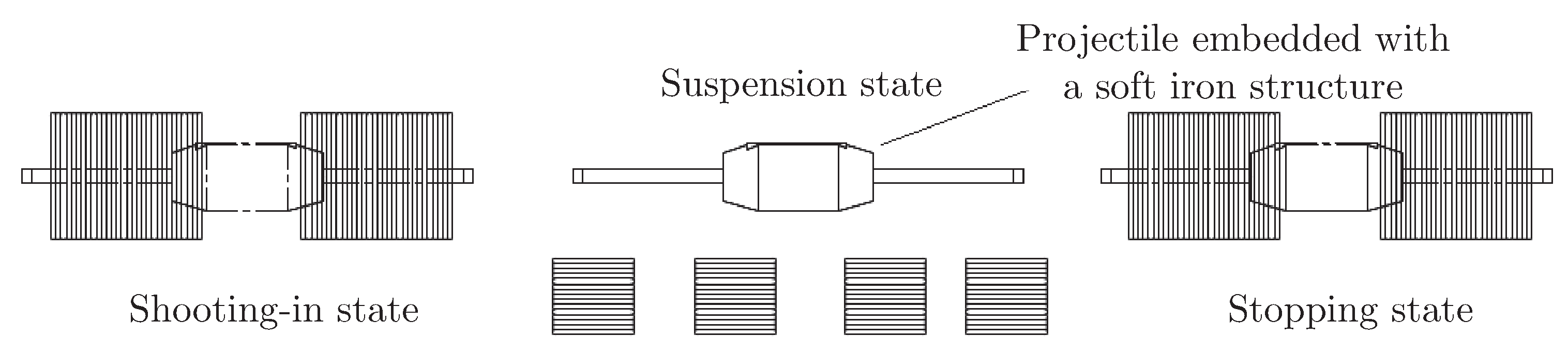
The following figure shows the three different states of the shuttle.
Figure 1.
Diagram of different states of the shuttle.
2.1. The Principle and Structure of Electromagnetic Projecting
The basic principle of electromagnetic projection is that the electromagnetic force drives an electrically charged conductor or a ferromagnetic object in a magnetic field. The electromagnetic projection mechanism is mainly composed of coil and shuttle, and the shuttle body is composed of the shed skeleton and embedded soft iron. Electromagnetic emission model is composed of power supply, switch, coil and shuttle, as shown in Figure 2. When the projectile is in front of the coil, the electromagnetic force attracts the projectile to move toward the centre of the coil and accelerates the projectile motion. The force slows the coil as it passes through the centre of the coil. The continuous acceleration of the coil can be guaranteed by controlling the on-off sequence of the coil [4].
The mechanism uses the electromagnetic force of the coil to accelerate the shuttle. After the shuttle moves to the other side of the coil, the electromagnetic force slow it down reversely. After the bobbin is loaded onto the yarn, the electromagnetic force will re-accelerate the shuttle and repeat the filling process, so that the shuttle does not need to be reversed itself.
The formula derivation is as follows:
According to electromagnetism theory [5], the magnetic flux density B of the axial component generated in the coil is:
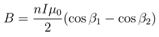
Figure 2.
Schematic diagram of shuttle throwing process.
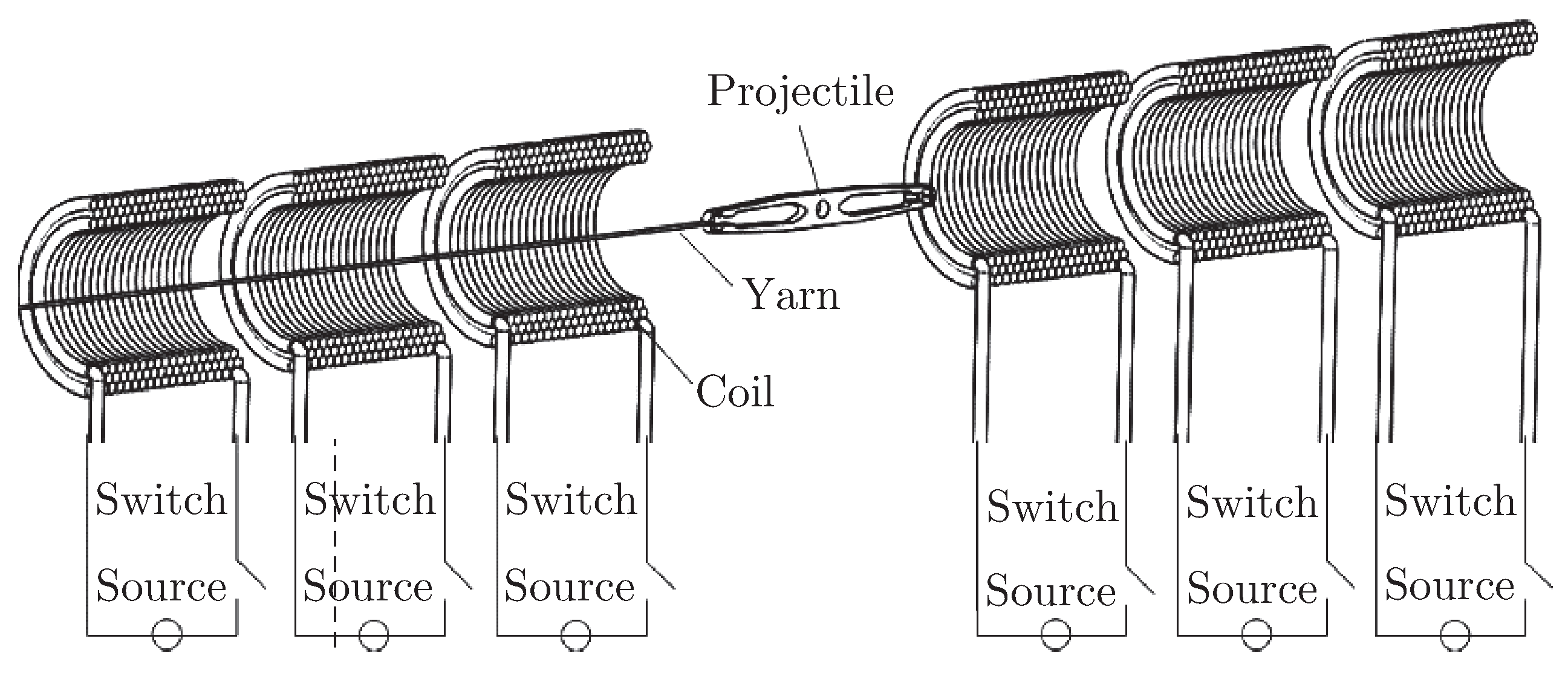
Figure 3.
Coil magnetic field anatomy.
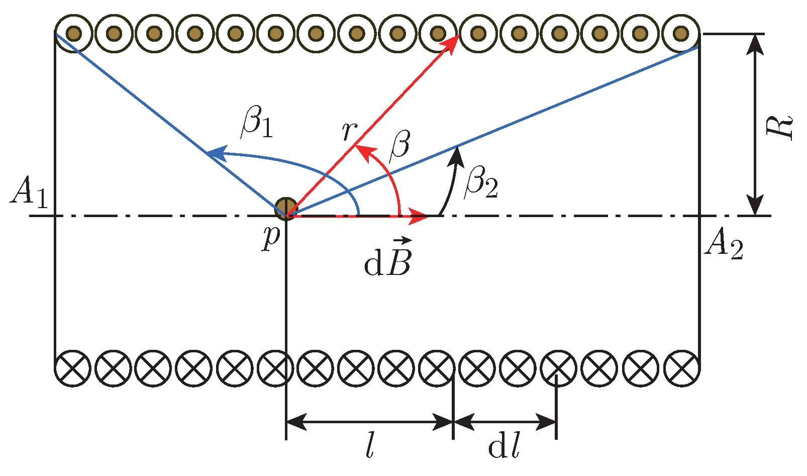
In the equation: n represents the number of turns per unit length; N represents the total turns of the coil; L represents the length of the coil; I represents the coil current; µ0 represents the permeability of air; β1 and the β2 represent the angles between the position of the coil on the inner axis and the two ends of the coil.
the magnetic flux Φ on every turn of the coil in equation 1 is as follows [6]:

In the equation: R represents the radius of the coil; S represents the cross-sectional area inside the coil. From inside the coil, the total number of flux of linkage Ψ is:
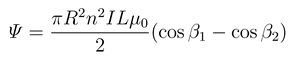
The magnetomotive force generated by the energizing coil is:
Fm = Ni = ΦRm
In this equation: Rm is magnetoresistance, Rm = lm/(µA); µ is the magnetic permeability of the shuttle material; lm is the length of magnetic circuit of the shuttle; A is the cross-sectional area of the magnetic circuit. For the coil, the magnetic flux Φ is constant, Φ and Ni show linear relationship, the magnetic energy stored in the coil Wm as follows:
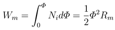
Equation 5 shows that magnetic energy Wm stored in magnetic field is a function of flux Φ and reluctance Rm,Wm = f(Ø,Rm). Based on the principle of virtual work, the force exerted on the bobbin in the coil can be derived, that is, the differential of the x direction of the moving axis in equation 5 can be obtained to get the thrust generated by the drive coil on the bobbin [7]:

In equation 6, dØ/dx express the change rate of magnetic flux with displacement.
Meanwhile, for the gripper in the magnetic field, its internal magnetic induction intensity is:
B = µH − µ0µrH
In equation 7, µr is the magnetic permeability of the shuttle material. µ is the relative permeability. H is the magnetic field strength inside the coil.
2.2. The Principle of Electromagnetic Levitation
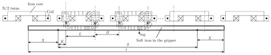
Since the speed of the shuttle is greater than 30 m/s [8], it is necessary to design a new reed sitting to reduce the friction between the shuttle and the sitting. The suspension controller is a magnetic levitation device composed of closed - loop electromagnetic structure. When the shuttles are projected onto an electromagnet array system, the suspended shuttles can overcome gravity with the force of the magnetic field and remain suspended in the center of the reed sitting.
Due to the influence of gravity, the flying shuttle will do parabolic movement, the width of the new shuttle weft is 8 meters. Without the sitting, the vertical difference in altitude during the projectile flight is about 20 mm at the speed of 30 m/s. Due to the difference in height, the new loom will carry out double weft insertion, which indicates that it needs an effective guide. The basic structure of electromagnetic levitation is shown in the following figure.
Figure 4.
Soft iron stress diagram of the shuttle.
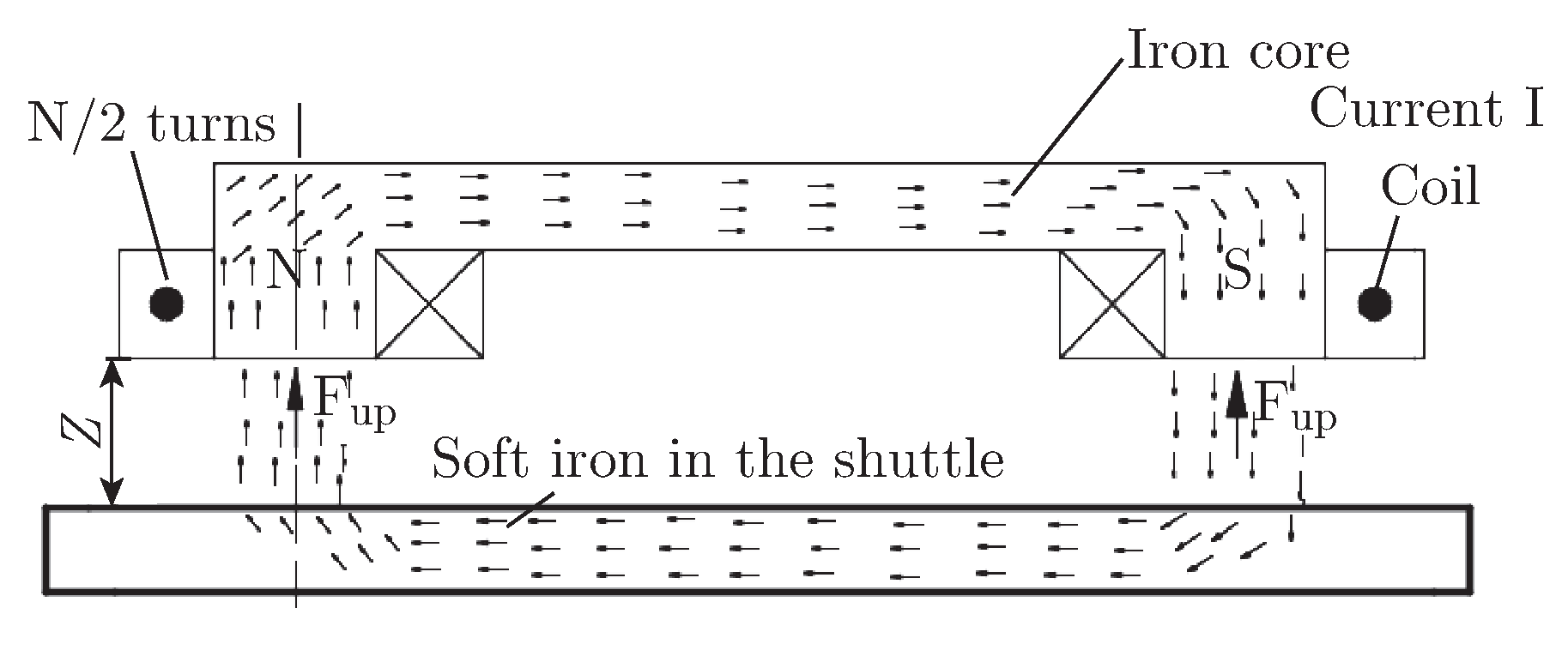
Among the picture, soft iron and iron core are ferric materials to improve magnetic permeability of magnetic circuit; The suspension height between the gripper and the coil is Z; Coil current size is I, coil turns number is N/2 turns per side, coil inner wall area is S, field strength generated by coil is B, magnetic conductivity is µ.
Magneto-motive force [9]:
Fm = NI
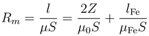
Magnetic resistance:

Flux:
ø = BS
Ohm’s law of magnetic circuit:

From the above formula:
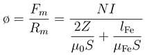
From Maxwell’s suction formula:

Formula:
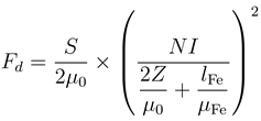
In equation 15, Fd is the magnitude of the total suction; S is the effective area of magnetic circuit of magnetic pole; while, µ0 is magnetic conductivity in vacuum; N is coil turns; I is coil current; Z is air gap height; and lFe is the equivalent total length of coil core and soft iron in gripper [10].
2.3. Dynamic Analysis
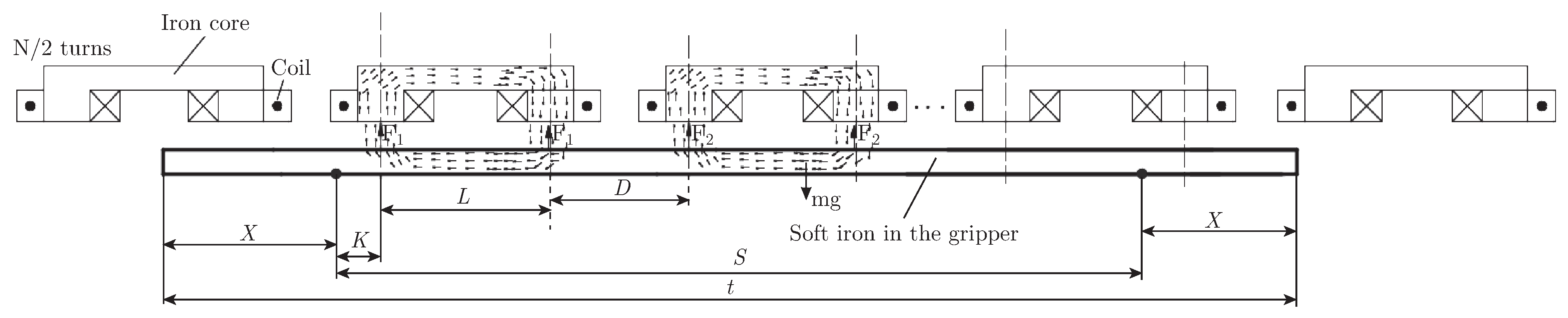
When the soft iron takes the gripper along flying in the suspension electromagnet array, the dynamic stress analysis is shown as follows:
In Figure 5, when the gripper is flying to from left to the right, the two red mark points on the gripper are the coil-end detecting point and the coil-start detecting point respectively. Suppose the number of driving sources to work simultaneously is n, then
t = 2 × X + (n + 1) × L + n × D
Figure 5.
Structure of filling insertion.
In Figure 6, Let the distance between the left node in the left-most excitation source and the left marking point is K, and the balance equation is [11]:

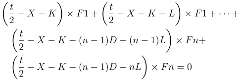
Figure 6.
Dynamic filling insertion analysis.
Due to too many parameters, we cannot be solved it by MATLAB according to equation 16, 17, 18, and we can’t get the relationship of them.
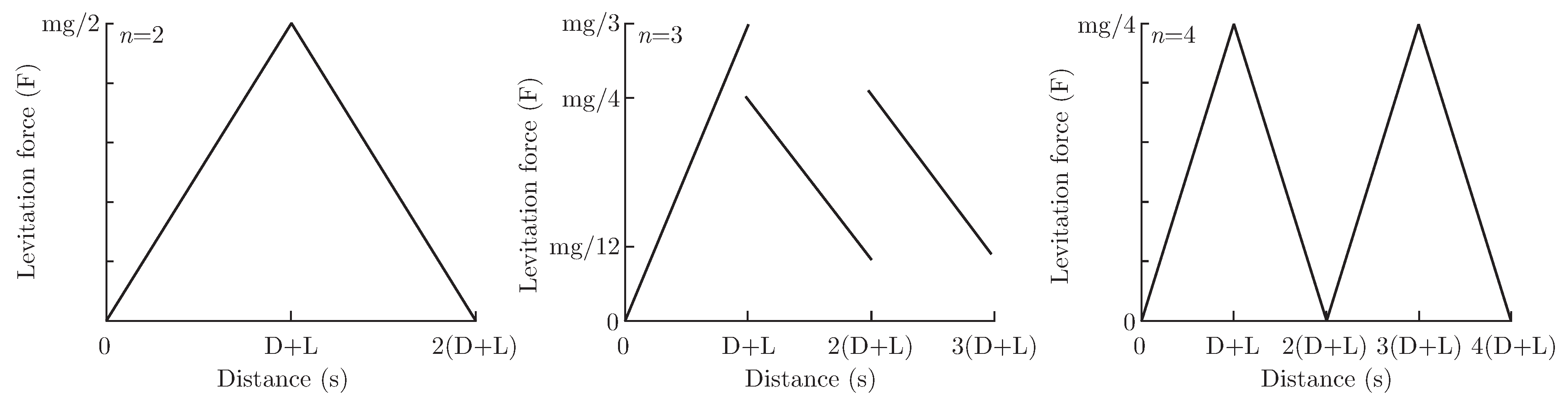
Solution: Set n (numbers of drivers working at the same time) as known quantity and consider them one by one. We need consider n = 2, 3, 4.
Reason: limited constraint conditions (there are only four equations: force balance, moment balance, initial condition, termination condition) [12].
It can be seen from the figure that the required suspension force is continuous when n = 2 and n = 4, which is convenient to achieve.
We can’t solve this problem because we have finite constraints when n > 5 [13].
After analyses of the above three cases, the feasible models are n = 2 and n = 4. Considering that increasing the levitation force of the excitation source requires increasing the current, coil heating is more serious. In this sense, the solution is better when n = 4.
Figure 7.
n relation with levitation force.
3. Electromagnetic Simulation
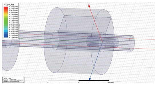
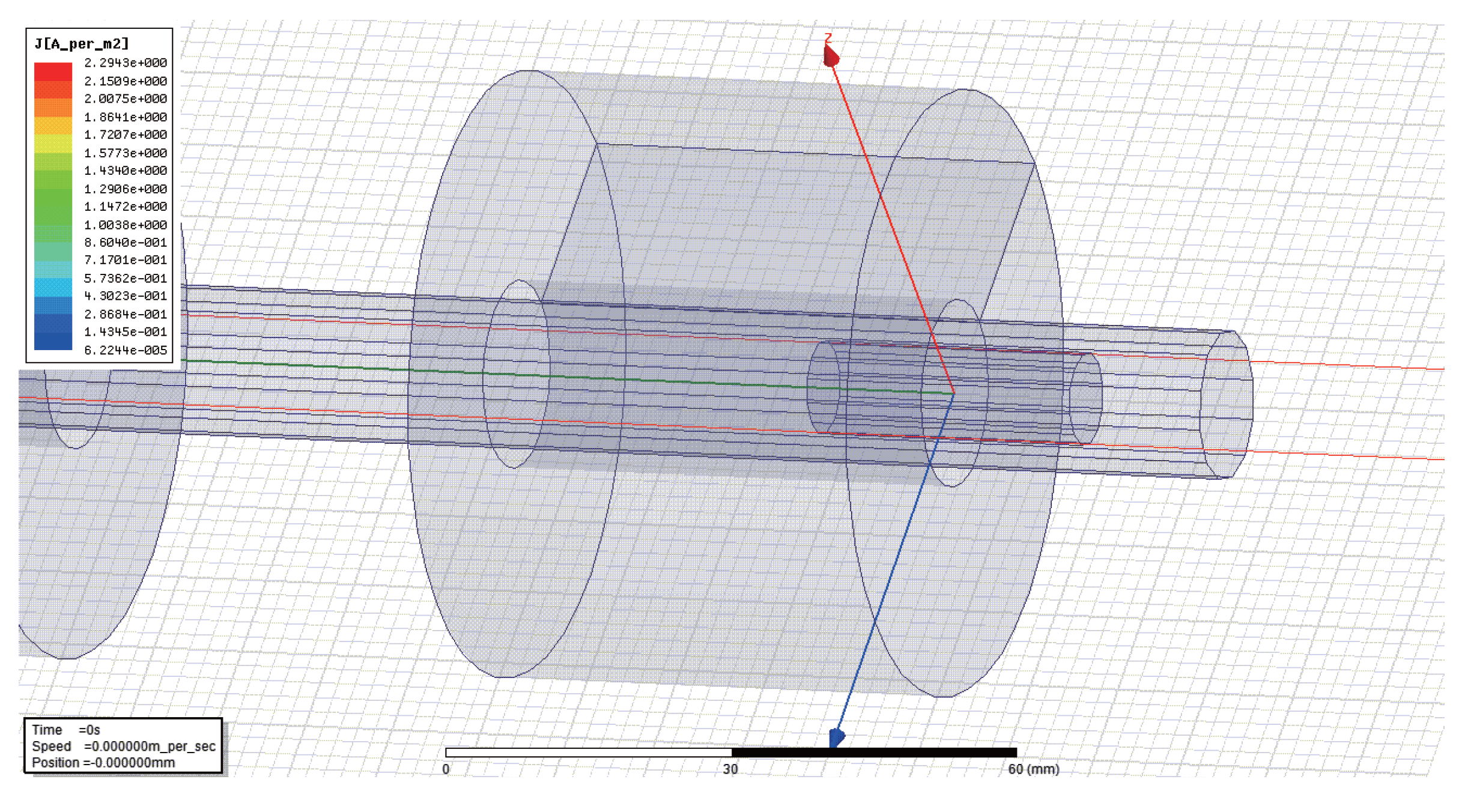
Before the experiment, we need to use software simulation to predict the feasibility of the experiment. Meanwhile, in the simulation process, the best parameters can be simulated to facilitate the experimental debugging. As shown in Figure 8, The experimental model consists of coil array and soft iron. and the coil is accelerated continuously by controlling the on-off of the coil sequence [14].
Figure 8.
Electromagnetic simulation diagram.
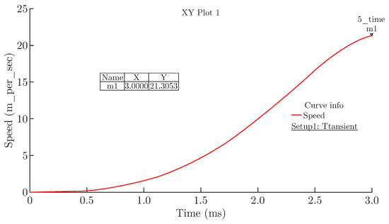
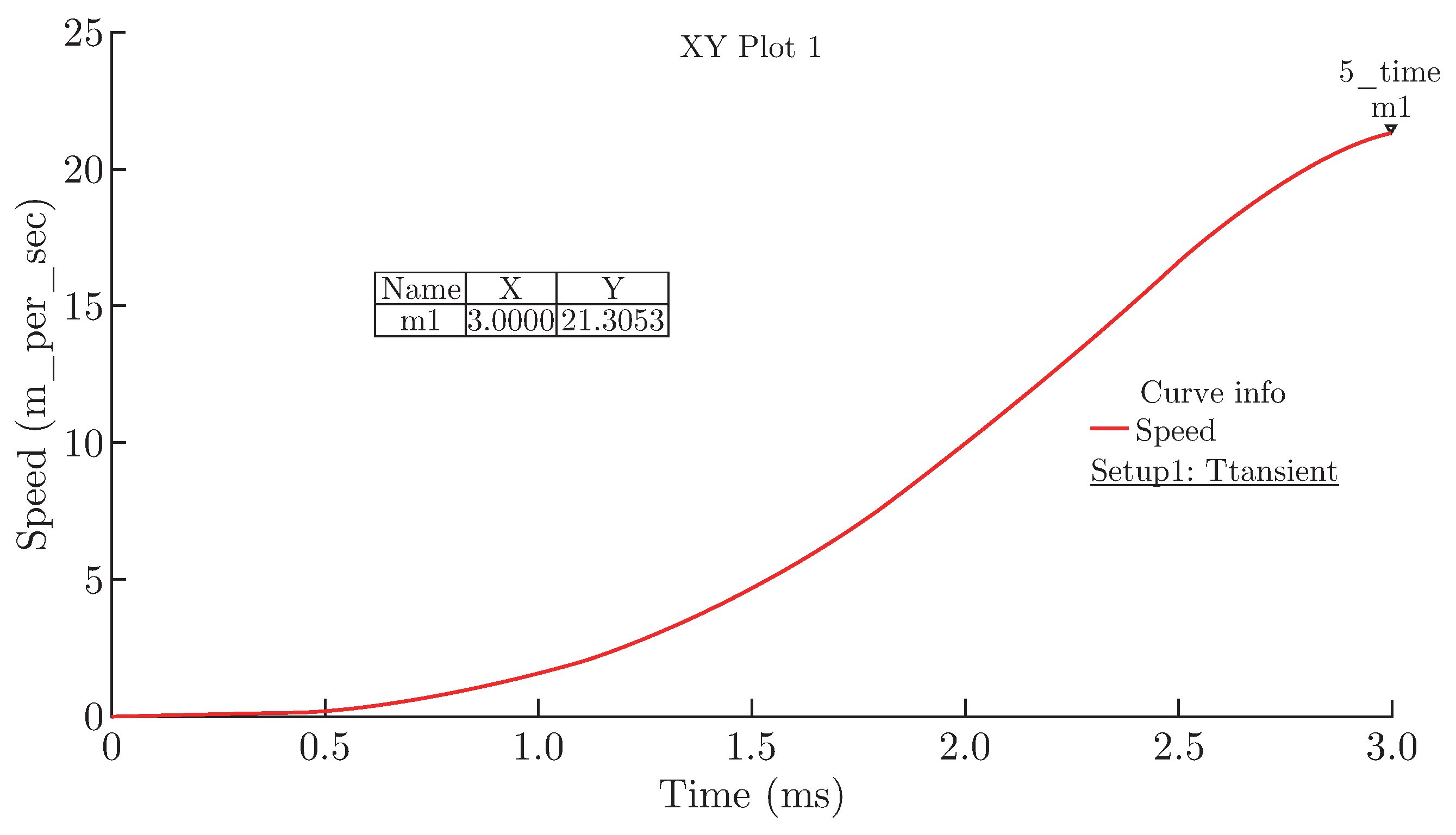
Figure 9.
Time-Velocity diagram.
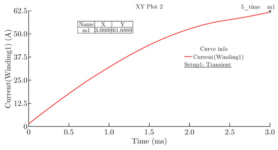
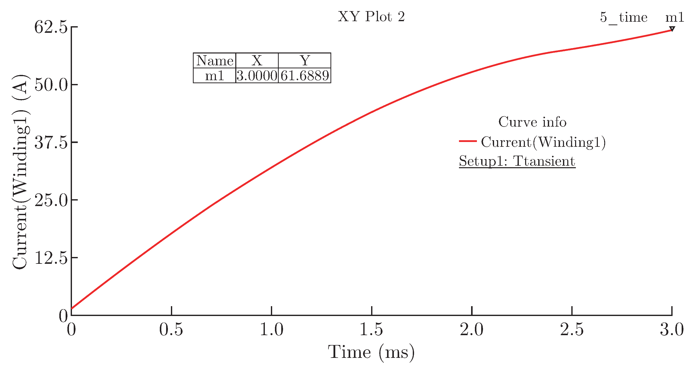
Figure 10.
Current-Time diagram.
Through simulation analysis, the shuttle speed can be up to 30 m/s.
After the projecting is completed, shuttle enters the process of levitation and insertion. At this point, the shuttle should be suspended and flying forward, and a controllable jitter can occur. The control of jitter needs to be adjusted through feedback. In the simulation process, the noise force should be as low as possible, the more stable the suspension force, the better.
Figure 11.
Electromagnetic levitation simulation diagram.
Figure 12.
Stress diagram in suspension state.
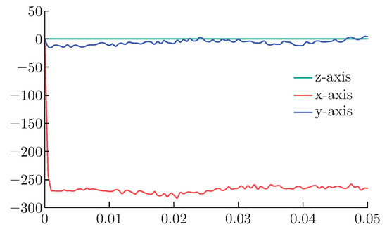
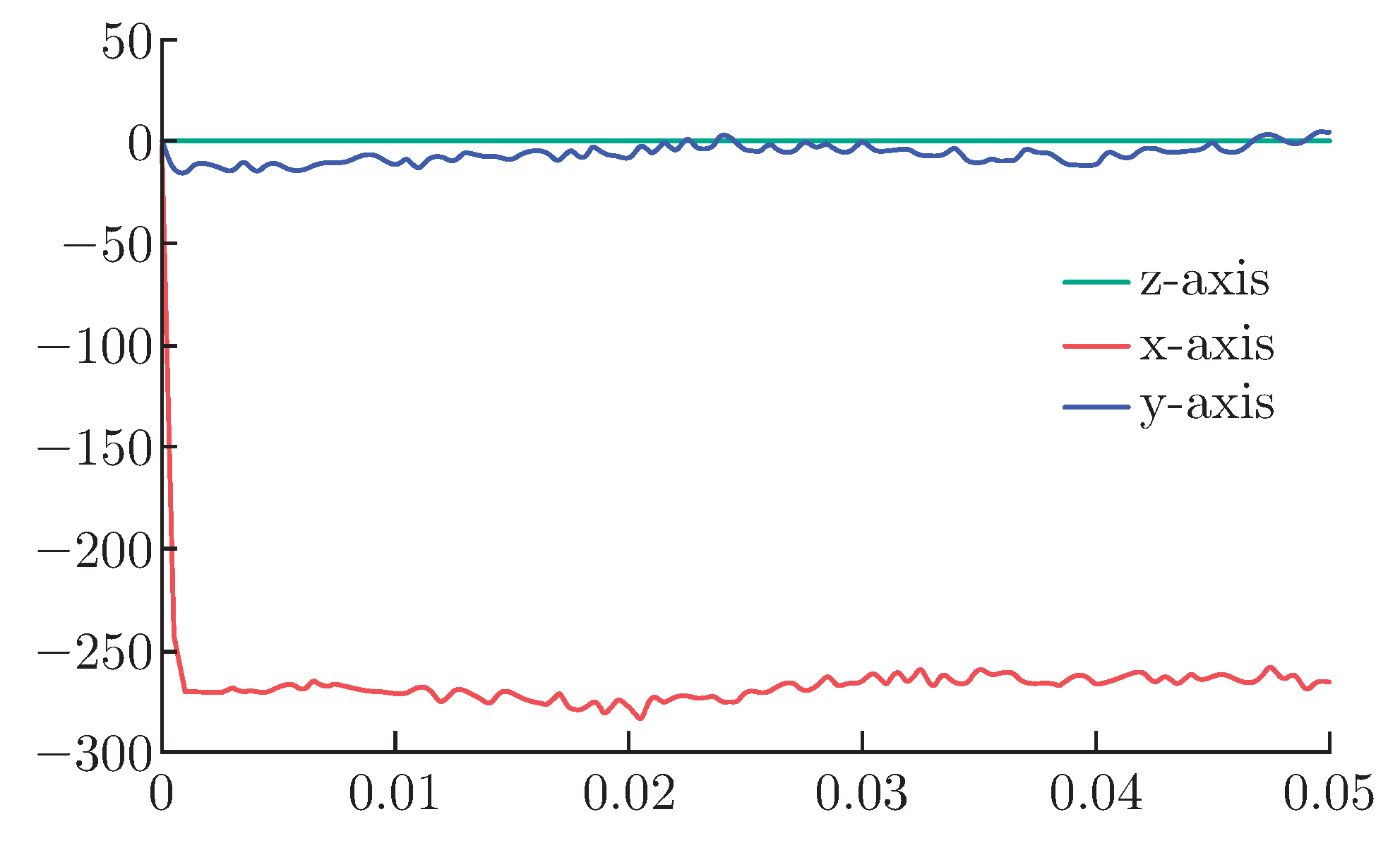
In Figure 12, the red line represents the force in the x axis, it’s the suspension force, and the blue and green lines represent forces in the y and z axes, they are the noise power. It can be seen from the figure that after the levitation force of the shuttle is basically stable passing the initial state, and the disturbance force in the other two directions is very small, indicating that this model is a feasible scheme. The gripper can be adjusted through feedback control to achieve dynamic stability [15].
4. Experiment and Result Analysis
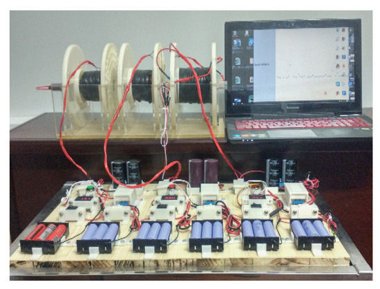
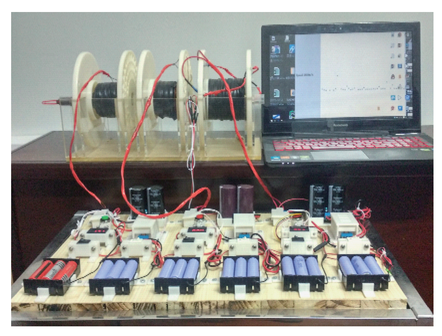
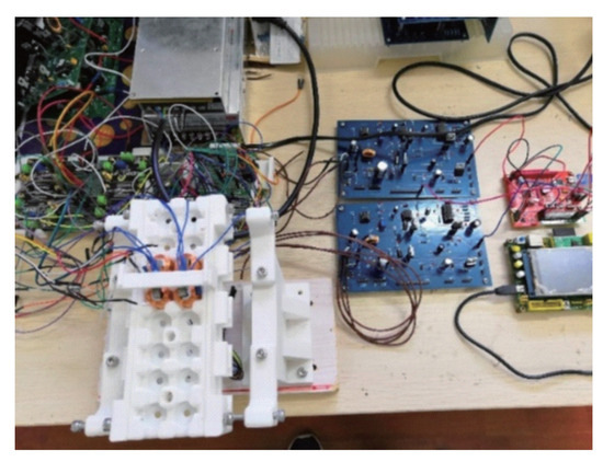
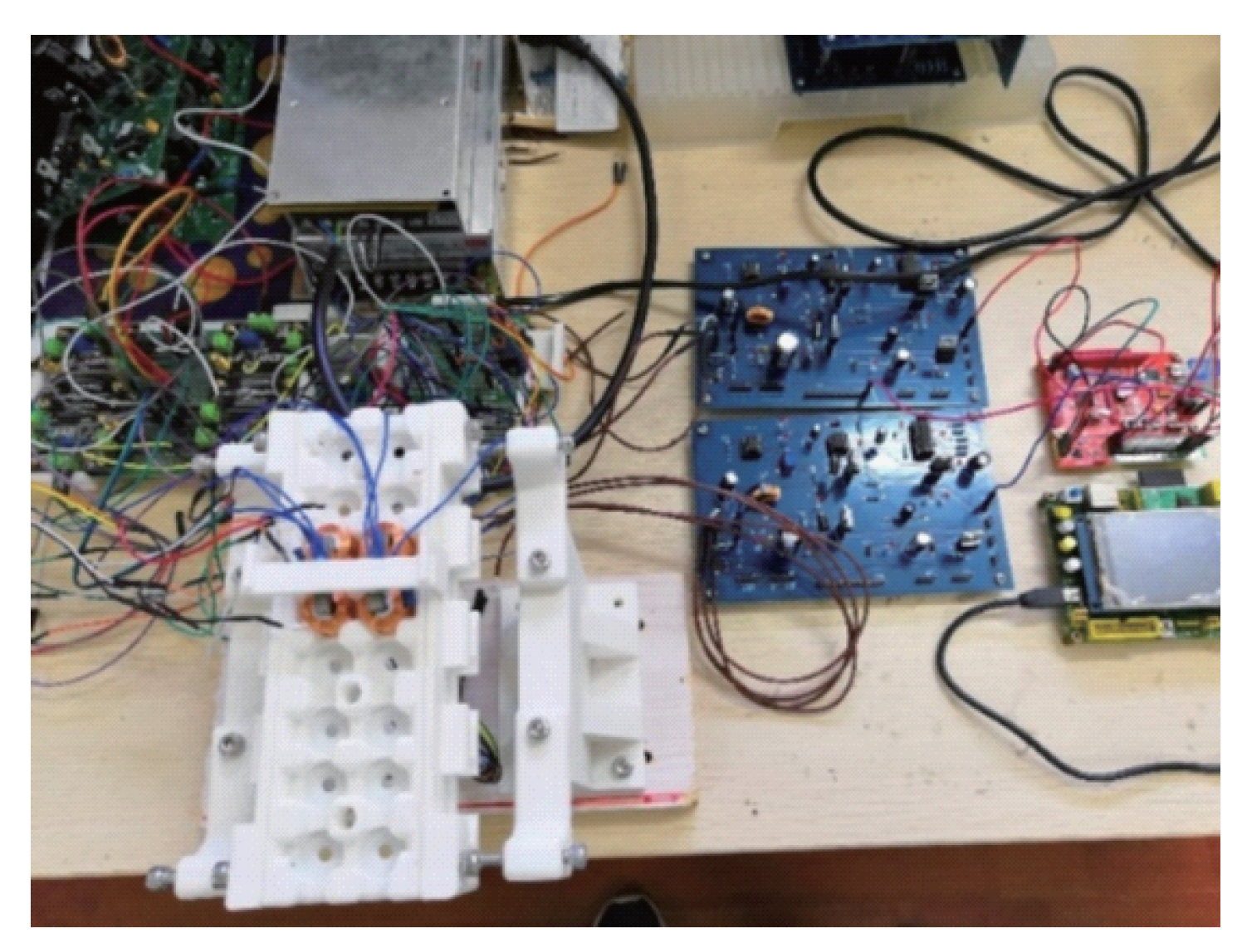
After the software simulation proves that the scheme is feasible, we start the experiment of electromagnetic projection and magnetic levitation. In the process of projection, velocity sensor is used to detect the velocity of the shuttle in real time, and dry battery and large capacitance are used as generating device of the magnetic field.
Figure 13 shows multistage electromagnetic emission/braking experimental device and Figure 14 shows electromagnetic suspension experiment diagram.
Figure 13.
Shuttle projecting diagram.
Figure 14.
Suspension weft insertion diagram.
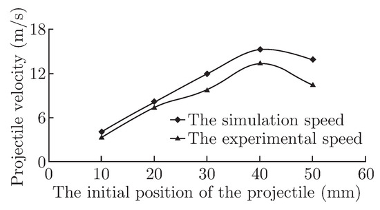
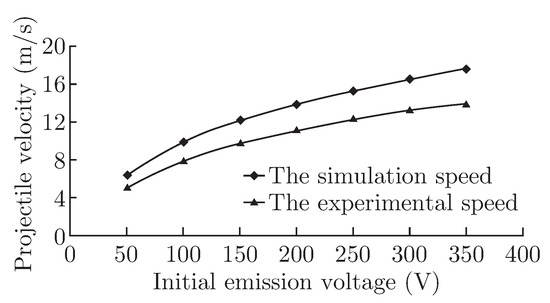
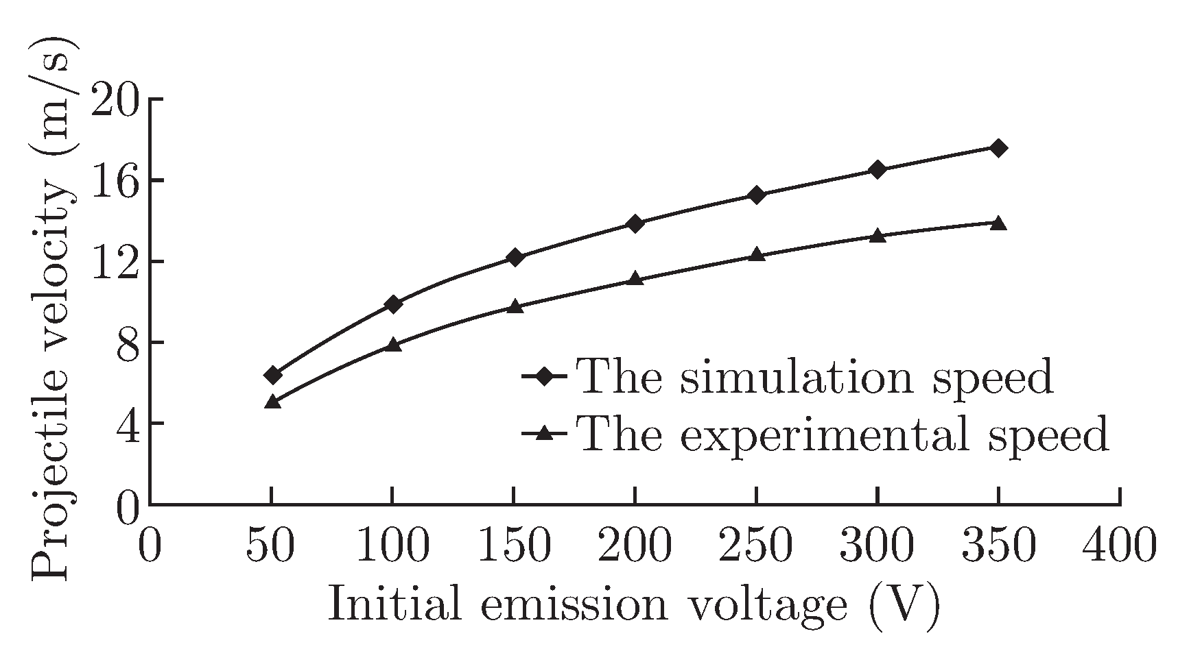
Experiments were carried out for different initial positions and different voltages.The experimental results are shown in Figure 15 and Figure 16. It can be seen that the experimental results are similar to the simulation results.
Figure 15.
Speed diagram with same voltage.
Figure 16.
Speed with same voltage position.
Figure 15 shows different exit velocities at different initial positions with the same voltage 250V and Figure 16 shows exit velocity at the same initial position at different voltage.
In the suspension stage, the real-time magnetic field is monitored through Hall sensor under the shuttle and the coil current is adjusted according to the control requirements. In order to improve response speed, the high speed operational amplifier module is used. Single chip microcomputer is used for voltage regulation responding to a four-way hall sensor.
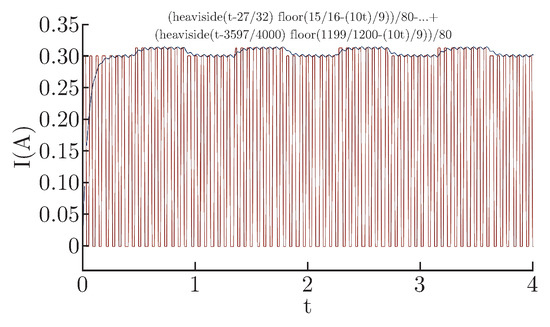
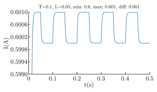
With the parameters above, as we can see in Figure 17, the response time reached 0.1 s, the experimental results show that the shuttle is vibrating up and down (in contact with the sensor and coil).
Figure 17.
PWM driver response diagram.
With changing the power supply:
Table 1.
Parameters used in the initial experiment.
Table 2.
Parameters table of power after changing.
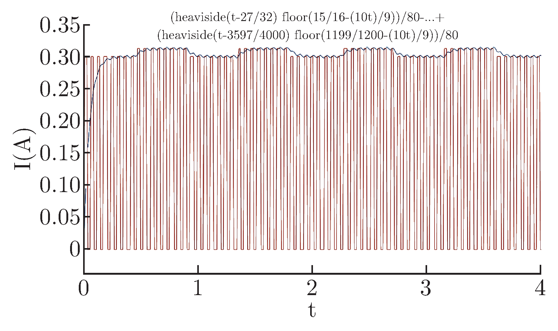
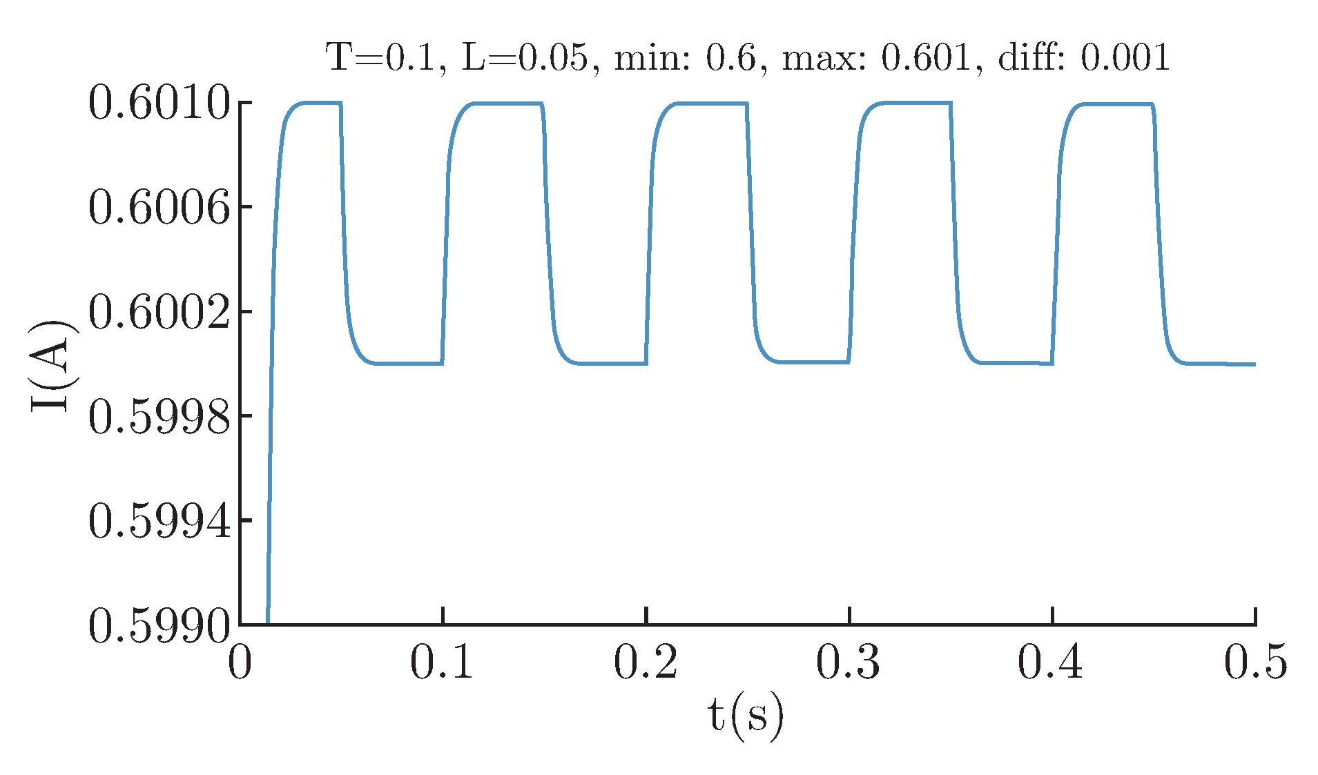
As we can see in Figure 18, by changing the driving mode and subdivision degree, shuttle jitter is reduced by 10 times, which basically meets the experimental requirements. In order to further ensure the stability of the experiment, the high-subdivision, low-deviation DAC circuit needs to be studied. The sensor with high performance and low power consumption is selected at the same time.
Figure 18.
DC driver response diagram.
5. Conclusion
This paper introduces a new electromagnetic-driven dual-directional weft insertion loom, electromagnetic transmitting mechanism and magnetic levitation system, after analyzes their working principle, it makes a detailed comparison with the original gripper loom after analyzing their working principle. The analysis results show that the structure of the new type of loom simplifies the structure of the loom, it can significantly improve the rate of weft insertion, and reduces the impact and vibration during the process of weft insertion with speed of 30 m/s. We use the built-in A/D module of stm32F4 to collect the magnetic field data of hall sensor HW101, and use the high-speed D/A module TLV5618 as the control unit of the coil output voltage. With a quick response and feedback, levitation becomes possible. this paper provides a basis for further research.
Acknowledgments
The work was supported by National Natural Science Foundation of China (Grant No. 51305309, 51875414) and Natural Science Foundation of Hubei Province, (Grant No. 2017CFB585).
References
- Chen, M. Torsion bar weft insertion mechanism. J. East China Inst. Text. Technol. 1981, 4, 48–55. [Google Scholar]
- Xu, H. Technical progress of projectile loom. Beijing Text. J. 2003, 4, 43–46. [Google Scholar]
- Duan, J. Analysis of weft yarn velocity on the projectile weaving machine. J. Xi’an Polytech. Univ. 2013, 6, 711–718. [Google Scholar]
- Zhang, H.; Kou, B.; Jin, Y.; et al. A cylindrical magnetic levitation gravity compensator with Halbach secondary structure. Trans. Chin. Electrotech. Soc. 2016, 6, 30–37. [Google Scholar]
- Liu, Z.; Chen, X.; Dong, J.; et al. The optimization of multistage electromagnetic launching system of mini-SHB. J. Exp. Mech. 2015, 1, 9–16. [Google Scholar]
- Yan, J. Electromagnetism; Press of University of Science and Technology of China: Hefei; p. 2.
- Wang, J.; Wu, H.; et al. Performance analysis and optimization of high speed switch valve based on PWM control mode. J. Hefei Univ. Technol. (Natural Science) 2016, 9, 32–35. [Google Scholar]
- Zhang, Z.; Wang, K. Design of switching power supply based on PWM control. Autom. Instrum. 2016, 1, 8–14. [Google Scholar]
- Qiu, Z.; Qi, Z. Finite element analysis of ANSYS - based magnetic levitation platform unloaded magnetic field. Des. Anal. 2014, 1, 24–32. [Google Scholar]
- Xiao, M.; Zhang, J. Stability control of active magnetic levitation system based on fuzzy adaptive control. J. Nanjing Univ. Aeronaut. Astronaut. 2013, 3, 35–42. [Google Scholar]
- Liu, H.; Hu, M. Adaptive fuzzy synovial-PID hybrid control scheme based on magnetic levitation vehicle system. Trans. China Electrotech. Soc. 2013, 6, 13–17. [Google Scholar]
- Zhao, S.; Gao, X. Control of nonlinear maglev system based on RBF neural network. J. Northeast. Univ. (Natural Science) 2014, 12, 32–40. [Google Scholar]
- Zhang, W.; Tang, H. Measurement of frequency response of magnetic coil. Acta Metrol. Sin. Vol.37(2016(1)), 31–37.
- Wei, L.; Li, B. Study on the effect of coil turns on response time of high speed switch electromagnetic field. Hydraul. Pneum. Seals 2018, 1, 15–22. [Google Scholar]
- Zhang, Y.; Liu, J. Responsed fast and magnetic core typed Rogowski coil. High Power Laser Partical Beams 2010, 8, 22–39. [Google Scholar]




© 2018 Textile Bioengineering and Informatics Society. This article is an open access article distributed under the terms and conditions of the Creative Commons Attribution (CC BY) license (https://creativecommons.org/licenses/by/4.0/).