


Abstract
Functional fibrous materials are a new family of fibre materials whose physical and chemical properties are sensitive to the change in the environment such as temperature, pressure, electric field, magnetic field, optical wavelength, adsorbed gas molecules and the pH value. This paper introduces a new approach to translate functions from nanoparticles to fibrous structures by co-electrospinning. Examples of nanofibres that have tailorable mechanical, electrical, magnetic, optical, thermal, hygroscopic, and antimicrobial functions are shown. The paper concludes with an example of the development of a multifunctional nanofibre scaffold for cartilage tissue regeneration.
1. Introduction
Stronger, faster, lighter, safer and smarter - these are the characteristics of extreme textiles presented in the 2005 exhibition by the Cooper-Hewitt, National Design Museum of the Smithsonian Institute in New York [1]. These characteristics are also applicable to the performance goals of a new generation of sportswear. About the same time, in 2004, an exhibition entitled “Beyond Fibres” was held in the National Museum of Emerging Science and Innovation (MeSci) in Tokyo [2]. In this exhibit the central role of a large family of fibres, including nanofibres, in providing new functions for products ranging from sportswear to space exploration was demonstrated. These events signify the entry of the fibre and textile industry into the new era of functional materials. The 2008 joint symposium of TBIS-SMART which focuses on the interaction between fibrous materials and human physiology and on sports medicine and rehabilitation therapy respectively provide a timely forum for the discussion of a new generation of enabling materials for SMART textiles in general and sportswear in specific.
Functional materials are a new family of materials whose physical and chemical properties are sensitive to the change in the environment such as temperature, pressure, electric field, magnetic field, optical wavelength, adsorbed gas molecules and the pH value. The functional materials utilize the native properties and functions of their own to achieve an intelligent action [3]. Functional materials in the form of fibres bring additional attribute as a carrier of the functions to higher order structures ranging from medical devices to clothing such as sportswear.
In the search for functional material concepts one can find abundant of clues in nature. In fact multifunctionality is a norm rather than exception in living systems. Fibrous materials in nanometer scale are the fundamental building blocks of living systems. From the 1.5 nm double helix strand of DNA molecules, including cytoskeleton filaments with diameters around 30 nm, to sensory cells such as hair cells and rod cells of the eyes, nanoscale fibres form the extra-cellular matrices or the multifunctional structural backbone for tissues and organs. Specific junctions between these cells conduct electrical and chemical signals that result from various kinds of stimulation. The signals direct normal functions of the cells such as energy storage, information storage and retrieval, tissue regeneration, and sensing. Analogous to nature’s design, nanofibres and their composites can provide fundamental building blocks for the construction of devices and structures that perform unique new functions. The areas expected to be impacted by the nanofibre based technology include drug delivery systems and scaffolds for tissue engineering, wires, super capacitors, transistors and diodes for information technology, systems for energy transport, conversion and storage, as well as smart structural composites for medical devices.
In this paper we introduce a new approach to translate functions from nanoparticles to fibrous structures by the co-electrospinning process. Examples of nanofibres that have tailorable mechanical, electrical, magnetic, optical, thermal, hygroscopic, and antimicrobial functions are presented. The paper concludes with an example of the development of a multifunctional nanofibre scaffold for cartilage tissue regeneration.
1.1. Nanofibre Effects
Nanofibres are solid-state linear nanomaterials characterized by flexibility and an aspect ratio greater than 1000:1. According to the National Science Foundation (NSF), nanomaterials are matters that have at least one dimension equal to or less than 100 nanometers. Therefore, nanofibres are fibres that have diameter equal to or less than 100 nm. It should be noted that this definition is often relaxed in the industry to include all fibres that have submicron diameter. Materials in fibre form are of great practical and fundamental importance. The combination of high specific surface area, flexibility and superior directional strength makes fibre a preferred material form for many applications ranging from clothing to reinforcements for aerospace structures. Some observations on the nanofibre size effect are presented herein.
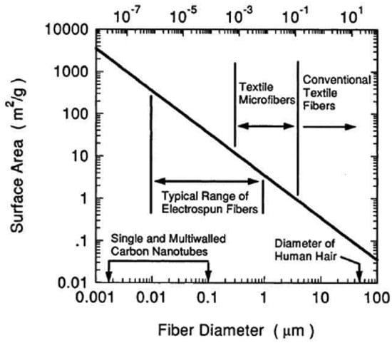
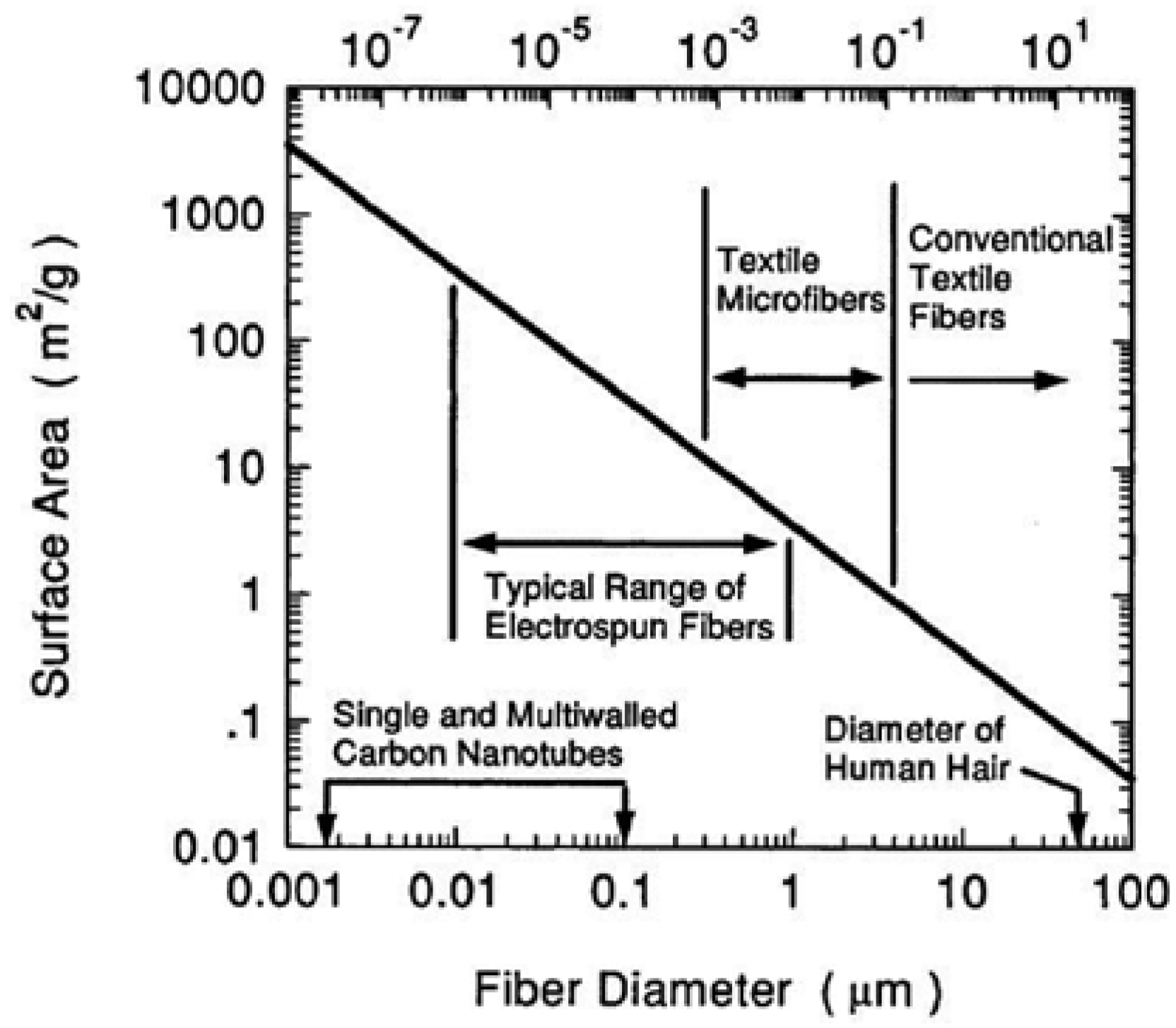
Effect of Fibre Size on Surface Area - One of the most significant characteristic of nanofibres is the enormous availability of surface area per unit mass. For fibres having diameters from 5 to 500 nanometers, as shown in Figure 1, the surface area per unit mass is around 10, 000 to 1,000,000 square meters per kilogram. In nanofibres that are three nanometers in diameter, and which contain about 40 molecules; about half of the molecules are on the surface. The high surface area of nanofibres provides a remarkable capacity for the attachment or release of functional groups, absorbed molecules, ions, catalytic moieties and nanometer scale particles of many kinds.
Figure 1.
Relationship of fibre diameter to surface area.
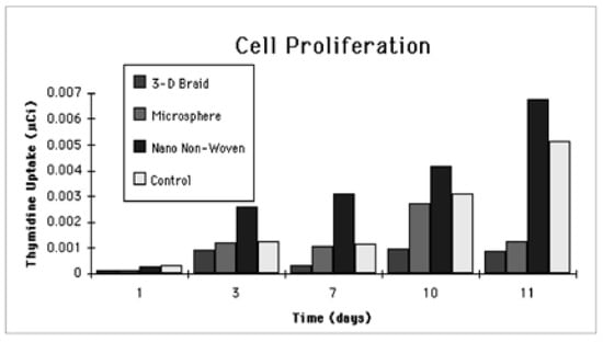
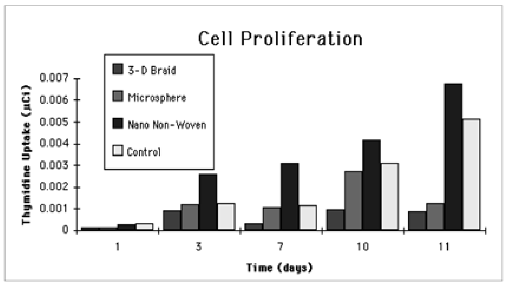
Effect of Fibre Size on Bioactivity -Considering the importance of surfaces for cell adhesion and migration experiments were carried out in our laboratory using osteoblasts isolated from neonatal rat calvarias and grown to confluence in Ham’s F-12 medium (GIBCO), supplemented with 12% Sigma fetal bovine on Polylactic-glycolic acid (PLAGA) sintered spheres, 3-D braided filament bundles and nanofibrils. [4]. Four matrices were fabricated for the cell culture experiments. These matrices include 1) 150 - 300 µm PLAGA sintered spheres 2) Unidirectional bundles of 20 m filaments 3) 3-D braided structure consisting of 20 bundles of 20 µm filaments 4) Nonwoven consisting of nanofibrils. The most proliferate cell growth was observed for the nanofibrils scaffold as shown in the Thymadinetime relationship illustrated in Figure 2 This can be attributed to the greater available surfaces for cell adhesion as a result of the small fibre diameter that facilitates cell attachment.
Figure 2.
Fibroblast cell proliferation as indicated by the Thymidine uptake of cell as a function of time showing that PLAGA nanofibre scaffold is most favorable for cell growth.
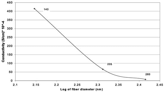
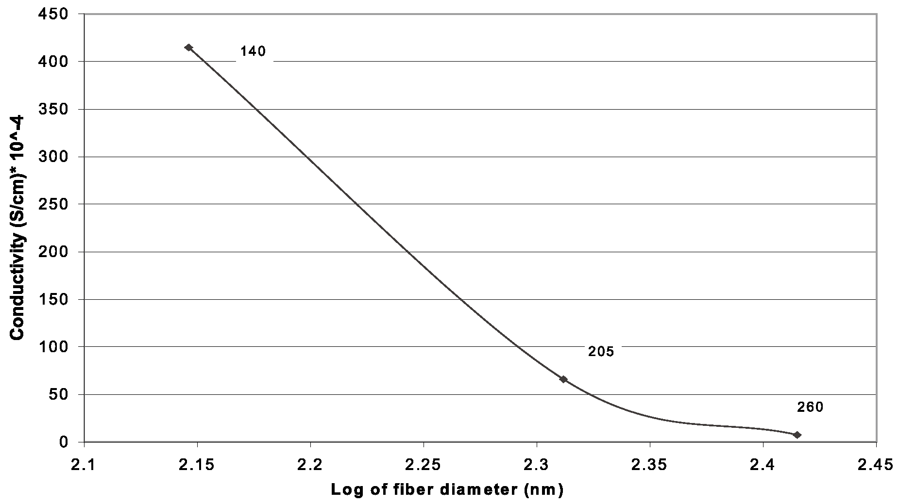
Effect of Fibre Size on Electroactivity - The size of conductive fibre has an important effect on system response time to electronic stimuli and the current carrying capability of the fibre over metal contacts. In a doping-de-doping experiment, Norris et al [5] found that polyaniline/polyethylene oxide (PEO) sub-micron fibrils had response time an order of magnitude faster than that of bulk polyaniline/PEO. There is three types of contact to a nano polymeric wire exist: Ohmic, Rectifying, and Tunneling. Each is modified due to nano effects. There exist critical diameters for wires below which metal contact produces much higher barrier heights thus showing much better rectification properties. According to Nabet [6], by reducing the size of a wire we can expect to simultaneously achieve better rectification properties as well as better transport in a nano wire. In a preliminary study [7], as shown in Figure 3 it was demonstrated, using submicron polyethyleneoxythiothene (PEDT) conductive fibre mat, that significant increase in conductivity was observed as the fibre diameter decreases. This could be attributed to intrinsic fibre conductivity effect or the geometric surface and packing density effect or both as a result of the reduction in fibre diameter.
Figure 3.
Effect of fibre diameter on electrical conductivity of PEDT nanofibres showing almost two order of magnitude increase in conductivity as fibre diameter decreases from 260 nm to 140 nm.
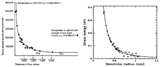
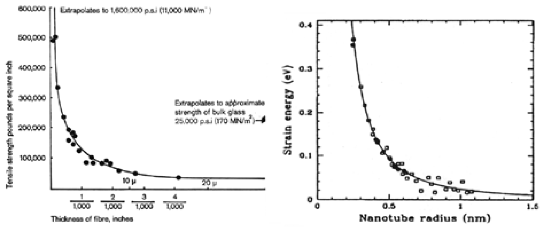
Effect of Fibre Size on Strength - Materials in fibre form are unique in that they are stronger than bulk materials. As fibre diameter decreases, it has been well established in glass fibre science that the strength of the fibre increases exponentially, as shown in Figure 4a., due to the reduction of the probability of including flaws or defects. As the diameter of matter gets even smaller as in the case of nanotubes, Figure 4b., the strain energy per atom increases exponentially, contributing to the enormous strength of over 30 GPa for carbon nanotube.
Figure 4.
Dependence of glass fibre strength on fibre diameter (4a) [8] and strain energy as a function of nanotube diameter (4b) [9].
1.2. The Electrospinning Process
Although the effect of fibre diameter on the performance and processibility of fibrous structures have long been recognized the practical generation of fibres down to the nanometer scale was not realized until the rediscovery and popularization of the electrospinning technology by Professor Darrell Reneker almost a decade ago [10]. The ability to create nanoscale fibres from a broad range of polymeric materials in a relatively simple manner using the electrospinning process coupled with the rapid growth of nanotechnology in the recent years have greatly accelerated the growth of nanofibre technology. Although there are several alternate methods for generating fibres in a nanometer scale, none matches the popularity of the electrospinning technology due largely to the great simplicity of the electrospinning process. In this paper we will focus on the electrospinning technology.
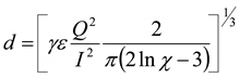
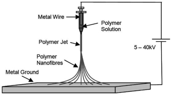
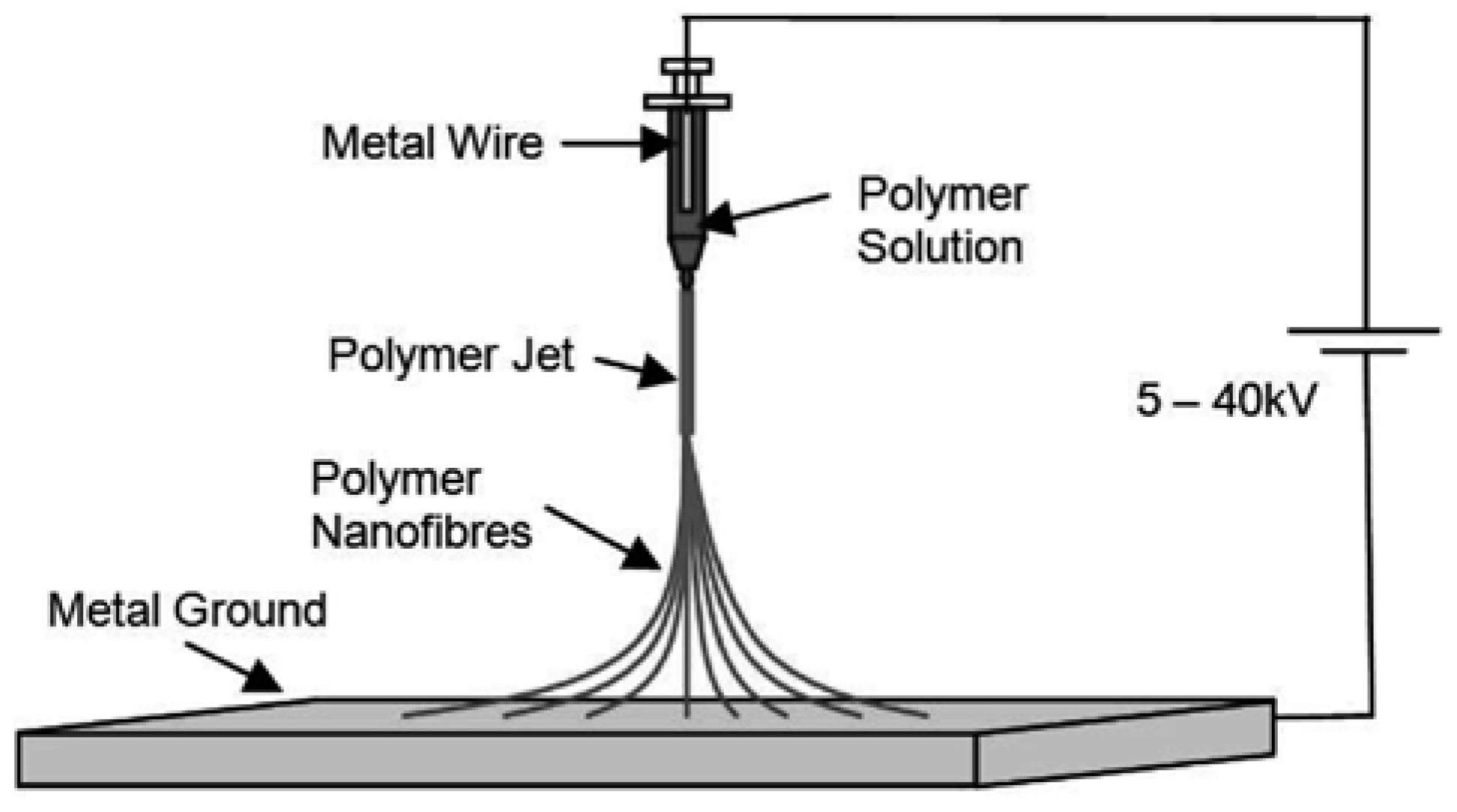
Techniques for electrostatic generation of ultra fine fibres (“electrospinning”) has been known since the 1930’s [11] This technique has found applications as high performance filters [12,13] and for scaffolds in tissue engineering [4] that utilize the unique characteristics of the high surface area (~ 103 m2/gm) provided by the nanofibres. In this non-mechanical, electrostatic technique a high electric field is generated in a polymer solution contained in a glass syringe with a capillary tip and a metallic collection screen. When the voltage reaches a critical value, the charge overcomes the surface tension of the deformed drop of the suspended polymer solution formed on the tip of the syringe and a jet of ultra fine fibres is produced. The electrically charged jet undergoes a series of electrically induced bending instabilities during its passage to the collection screen that results in the hyper-stretching of the jet. This stretching process is accompanied by the rapid evaporation of the solvent molecules that reduces the diameter of the jet in a cone shape radius. The dry fibres are accumulated on the surface of the collection screen resulting in a non-woven mesh of nano to micron diameter fibres. A schematic drawing of the electrospinning process is shown in Figure 5 The process can be adjusted to control the fibre diameter by varying the electric field strength and polymer solution concentration, while the duration of electrospinning controls the thickness of fibre deposition [4,12]. According to Rutledge et al [14], the diameter of electrospun fibres is governed by the following equation:
where d =fibre diameter; γ = surface tension; ε = dielectric constant; Q = flow rate; I = current carried by the fibre; and χ= ratio of the initial jet length to the nozzle diameter.
 | (1) |
Figure 5.
The electrospinning process.
The fibre diameter can be controlled by adjusting the flow rate, the conductivity of the spinning line, and the spinneret diameter. Fibre diameter can be minimized by increasing the current carrying capability of the fibre through introduction of a conductive filler such as carbon black, carbon nanotube, metallic atoms or mixing with an intrinsically conductive polymer. An increase of current carrying capability of the fibre (I) by 32 times will bring about ten-fold decrease in fibre diameter. Alternatively, if the current, I, is kept constant, one can bring about a ten-fold decrease in fibre diameter by reducing the flow rate by 32 times. Reducing the spinneret nozzle diameter can also bring about a reduction in fibre diameter. When the χ value increases from 10 to 1000, the diameter of the fibre will decrease by approximately 2 times.
While the Rutlege equation provides a reasonable link between fibre diameter and process control parameters, it ignores the intrinsic properties of the spinning dope such as molecular conformation, which relates to the polymer concentration and molecular weight. To address this issue we introduce a dimensionless parameter, the Berry number Be [15] expressed in terms of the product of intrinsic viscosity, [η], and the concentration K of the polymer spinning dope.
Be = [η] × K
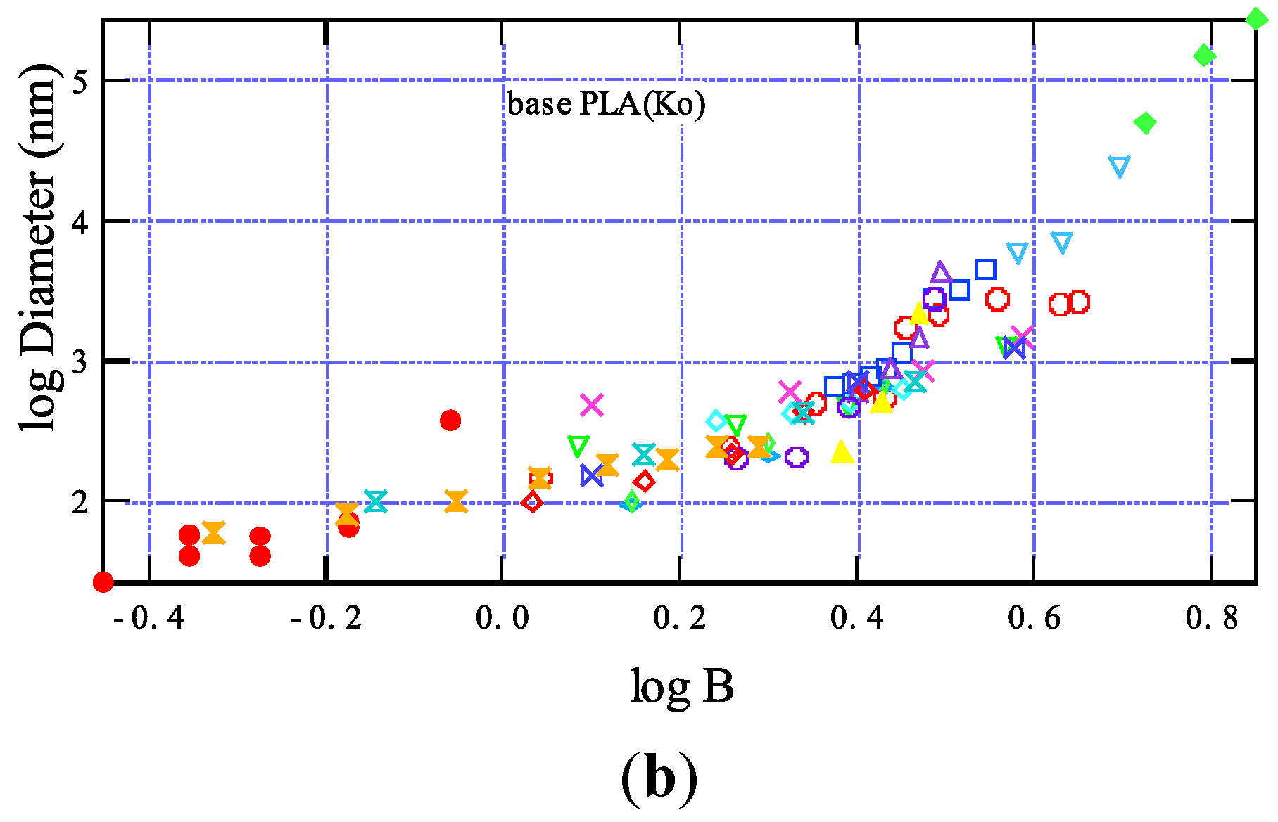
The intrinsic viscosity [η] of the polymer is the ratio of specific viscosity to concentration at infinite dilution. The intrinsic viscosity is also closely related to molecular weight of the polymer. It has been found that the degree of entanglement of polymer chains in solution can be described by Be [15]. In very dilute solutions, when the Be is less than unity, the polymer molecules are sparsely distributed in the solution, and there is a low probability for the individual molecules to entangle with each other. At Be greater than unity and as the polymer concentration increases, the level of molecular entanglement increases and results in a more favorable condition for fibre formation. Buildig on the concept of the Berry number Ko and Yamashita found a simple law governing the formation of nanofibres from various polymers by relating fibre diameter to the Berry number as expressed by the following equation [16]:
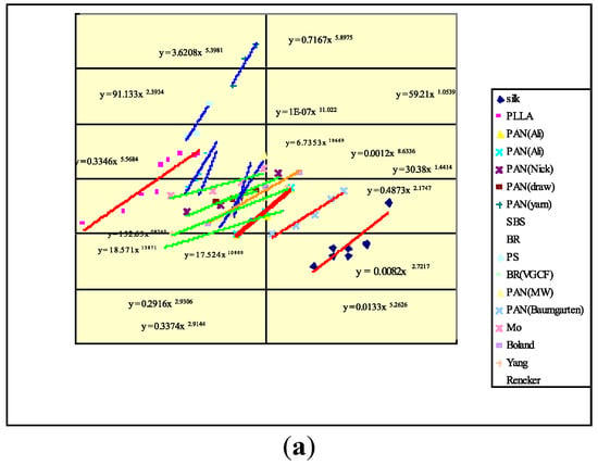
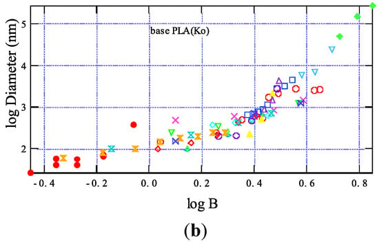
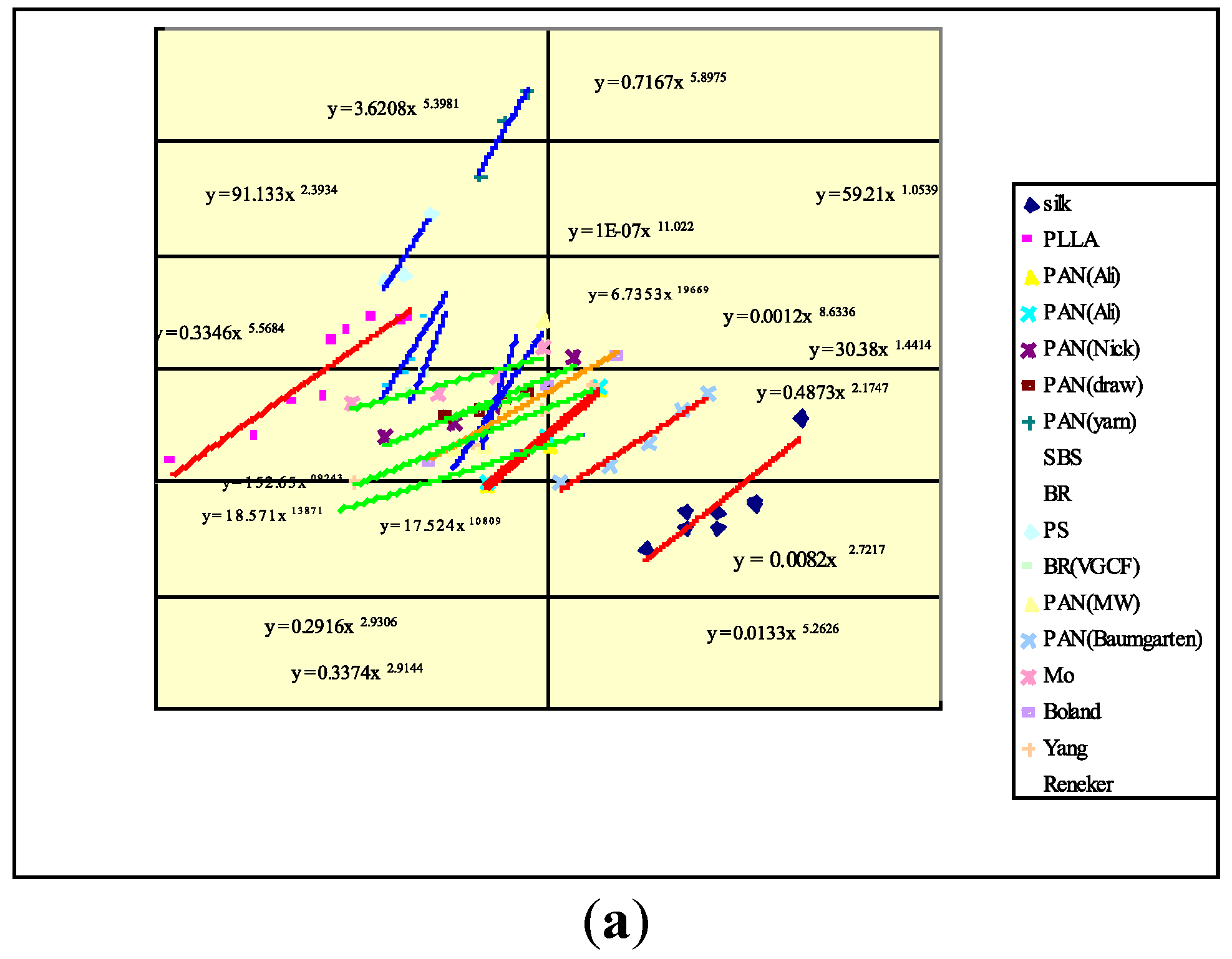
where A and C are constants. That is to say, the diameter D of the nanofibre is shown to have a power law relationship to the Berry Number Be. Figure 6(a) shows the diameter-Berry number relationship of some of the polymers that we examined. Based on our observation of a large number of polymers a master curve was constructed by horizontally shifting an individual plots as shown in Figure 6(b). Equation 1 and 3 provide guidance for the selection of processing parameters in electrospinning.
D = A(Be)C
Figure 6.
(a) Relationship between fibre diameter and Berry Number; (b) Master curve of fibre diamater-Berry number relationship for electrospun fibres.
2. Functional Nanofibres
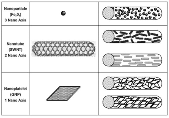
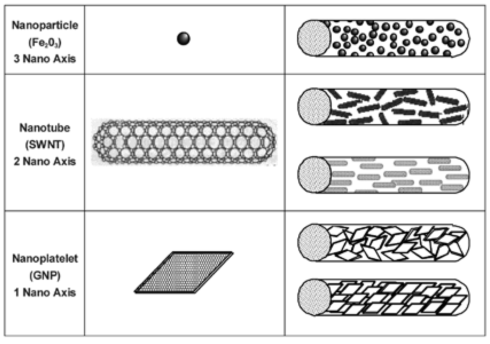
Nanoparticles of various geometries and shapes can be combined with a suitable polymer matrix to form composite nanofibres. Among various available nanomaterials in 0-D, 1-D, and 2-D geometry as illustrated in Figure 7 and summarized in Table 1, magnetic nanoparticles, quantum dots, photocatalytic nanoparticles and carbon nanotubes are excellent examples of nanoparticles that can be incorporated into electrospinning process to fabricate composites fibres with interesting functions. We demonstrated that the nanocomposites fibres produced by coelectrospinning can mechanically stabilize particles and capable of transforming into complicated structures while maintaining the nanoparticles properties. The nanoparticle embedded nanocomposite fibres not only improve mechanical properties but also introduce new functions in the form of fibres. Iron oxide nanoparticles can be used for biomedical applications, electromagnetic interference shielding, catalyst and sensors [17]. Quantum dots such as CdS, CdSe and ZnS can be used in semiconductive devices, biological labeling and optical switches [18,19]. TiO2 particle has been known for its strong photocatalytic properties for filtration and antibacterial applications [20]. Carbon nanotubes has brought a great attention for its superb mechanical and electrical properties [21]. Creating nanocomposite fibres through the electrospinning process using nanosize particles has been previously explored and successfully demonstrated as shown in the following examples. Previous work of carbon nanotubes (CNT) nanocomposite fabrication by Ko et al showed that co-electrospinning provides an excellent means for the translation of the mechanical properties of CNT to polymer fibril matrix by the inclusion of a small amount of CNT. For example, a 4 to 5 fold increase of mechanical properties was found with the introduction of less than 1.5% by weight of CNT to the polyacrylonitrile (PAN) matrix nanocomposite fibres [21]. In order to explore the feasibility of using nanocomposites as interior materials for buildings and houses, such as shoji paper, wallpaper, and fusuma paper, the thermal insulation properties of nanocomposites consisting of Cloisite 15A-nanoclay reinforced polyvinylidinefluoride (PVDF) in film and fibrous forms, were evaluated. A 10 times higher thermal insulation values was observed for the nanoclay filler nanofibrous structures [22]. Goto et al demonstrated that the incorporation of silica particles into PA66 nanofibres led to significant improvement of the tensile properties. They also found that PAN/silica composite nanofibres synthesized by blending PAN and aliphatic polyester (APES) showed good adsorption property with hydrophilic molecules of bromothymol blue, i.e. PAN/APES composite nanofibres efficiently captured the hydrophobic molecules [23]. Carbon free selective permeable membranes were developed by Ko et al using TiO2 filled polyurathane nanofibres. These composite fibre membranes were demonstrated to be capable of repelling Chem/Bio agents while allowing the body moisture vapor to escape [24]. Yang and Ko developed antimicrobial fibrous scaffolds using photocatalytic composite nanofibres by coelectrospinning of 60 nm TiO2 nanoparticles with PVDF. The photocatalytic effect was confirmed using methylene blue dye bleaching caused by TiO2. A 3wt% of TiO2 content in the fibre was found to be effective in the antiviral activity in the E. Coli culture. It was also found from bovine osteoblast culture that higher amount of TiO2 particles facilitate higher cell attachment and proliferation [25]. By introducing a small amount of carbon nanotube into PEDT, an intrinsically conducive polymer, a ten-fold increase in electrical conductivity was demonstrated by Ko et al for the co-electrospun nanofibre mats [7].
Figure 7.
Geometry of nanoparticles for co-electrospinning.
Table 1.
Functions of composite nanofibres.
In this paper the processing, structure and properties of quantum dot (CdS) filled fluorescence nanofibres and magnetic nanoparticles (Fe3O4) filled nanofibres produced by co-electrospinning are used as examples to illustrate the concept of functional composite nanofibres.
Fluorescent Nanofibres - Quantum dots (QDs) are semiconductor nanocrystals with diameters ranging typically from 2 to 10 nm. When excited by sufficiently high energy, electrons of semiconductor in the valence band can overcome the band gap and jump into the conduction band. Being unstable at the high-energy state, the electrons recombine with the holes in valence band, releasing energy by emitting photons. For example, QDs can be excited by UV light and emit visible light. Due to the quantum confinement effect, QDs exhibit distinctive and controllable photoluminescence properties by controlling band gap that can be tailored by material selection and varying the particle size. Both organometallic and aqueous synthesis methods have been developed to produce various QDs with excellent properties [26].
The advantages of QDs over the traditional fluorescent molecules include tunable fluorescence colors, controllable excitation along with narrow emission spectra, and high intensity of emission, good photostability, and long fluorescence lifetime. This enables QDs to be used as powerful imaging and tracking tools in various biological and medical applications. By immobilizing an antibody on their surface, QDs can bind selectively to a particular antigen and may be used to locate the cells selectively [27]. QDs can also be used as chemical sensor, which respond selectively to physiologically important metal cations, such as Zn2+, Cu2+, and detect the explosive 2,4,6-trinitrotoluene (TNT) in aqueous environments [28]. Depending on the synthesis method QDs exist as particles dispersed in aqueous or organic solvents. Dried QD powders can be obtained from these solutions according to application needs.
To fabricate fluorescent composite nanofibres quantum dots from cadmium sulphide (CdS) were prepared using an environmentally friendly and lowcost synthesis procedure [29]. Unlike traditional organometallic method this procedure has an advantage of utilizing one-step reaction of simple inorganic precursors. An aqueous solution of CdS QDs was prepared in water by the reaction between cadmium nitrate [Cd(NO3)2] and sodium sulfide [Na2S] with 3-mercaptopropionic acid [MPA] as the capping molecules. The resultant clear aqueous QDs suspension remains stable for more than 12 months at 4°C away from light.
Electrospinning dopes were prepared by dissolving 5 % PEO (Mw 600,000, purchased from Sigma) by weight into various concentrations of aqueous CdS solution by magnetically stirring for 24 hours. The prepared PEO-CdS spinning dopes were then transferred to a glass syringe containing 18-gauge needle and was electrospun. 5% PEO was electrospun with 1.6 mM, 6.4 mM and 12.8 mM concentrations of aqueous CdS. A spinning distance of 15 cm and voltage of 15 kV were found to be optimum conditions for the formation of continuous and uniform nanofibres free of beads or droplets.
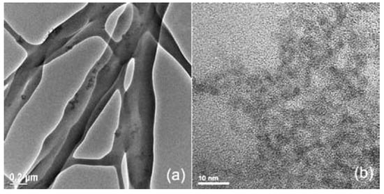
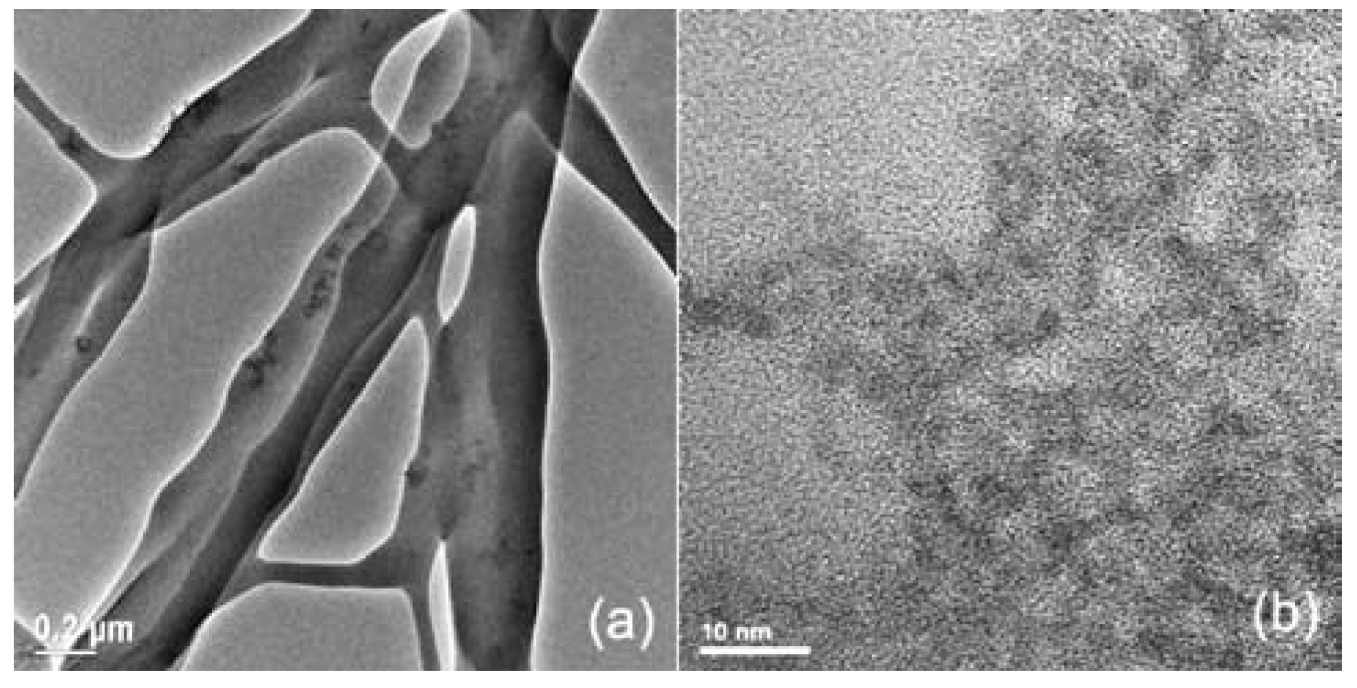
TEM was used to confirm the presence of CdS nanoparticles in the fibres. TEM images of the PEO-1.6 mM CdS electrospun fibres and as-prepared CdS solution are shown in Figure 8 Figure 8a shows the presence of the CDs in the PEO fibres and CdS particles obtained from aqueous solution is shown in Figure 8b. The synthesized particle sizes were 5~6 nm in diameter. Localized CdS particle aggregations were observed in some part of fibres and well distribution of particles as well.
Figure 8.
TEM of CdS particles and electrospun CdS-PEO fibre.
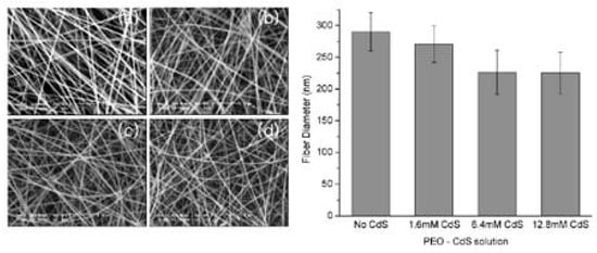
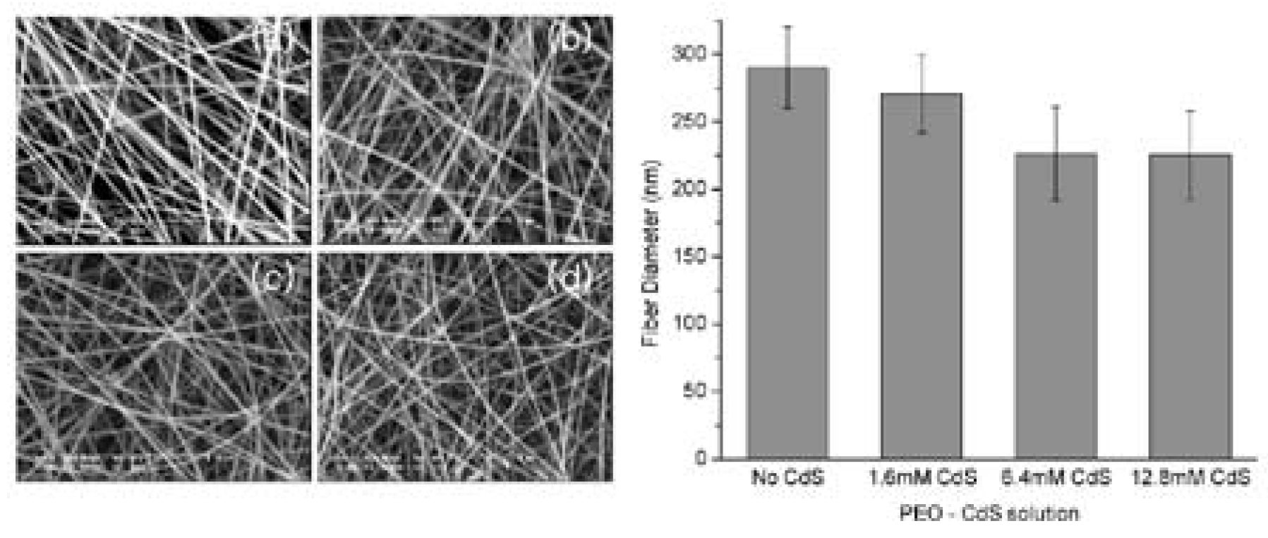
The average fibre diameter obtained from 5 wt% PEO-water solution without CdS particle was 290 nm. The average diameter of the fibres with different combinations of CdS solution concentration were 271 nm, 226 nm and 225 nm for the 5 wt % of PEO dissolved in 1.6 mM, 6.4 mM and 12.8 mM of CdS solution respectively. Figure 9 shows the fibre morphology and diameter distribution of various nanocomposite structures. Fibre diameter tends to decrease as CdS concentration increases. It has been known that electrical properties of solution and electrical field strength applied to solution during the electrospinning play an important role in the fibre forming. It is believed that the inclusion of CdS particles alters the electrical properties of the solution thus cause the decrease of fibre diameter. However validity of this theory needs to be confirmed in the future with the consideration of multiple parameters such as conductivity, dielectric permittivity, solution surface tension, solution viscosity…etc.
Figure 9.
ESEM of fibres and average fibre diameter (a) 5 wt% PEO in water (b) 5 wt% PEO in 1.6 mM CdS, (c) 5 wt% PEO in 6.4 mM CdS, (d) 5 wt% PEO in 12.8 mM CdS.
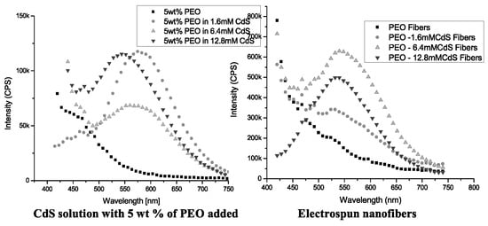
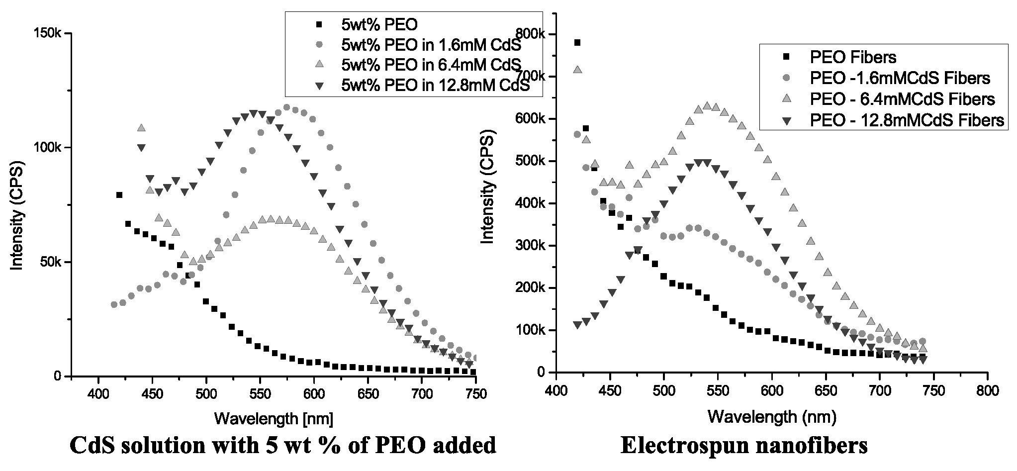
In Figure 10, Photoluminescence (PL) of the CdS-PEO solution and electrospun fibres were measured using a QM-4/2005 spectrofluorometer (Photon Technology International, Birmingham, NJ) with excitation and emission slit width of 2 nm. The photoluminescence spectra showed that lower concentration of as-received CdS had relatively higher emission intensity. This is believed to be in part due to higher concentration of excess MPA and other ions in CdS suspension produced during the synthesis of in the higher concentration of CdS solution. Also, higher concentration might promote the formation of CdS clusters trapping the charge carriers in the interfacial states and preventing the electron-hole recombination. The neighboring clusters might absorb the emission by another particle thereby reducing the PL intensity.
Figure 10.
Photoluminescence of CdS-PEO solution and electrospun fibre.
As shown in Figure 10, the pure PEO-water solution did not show fluorescence property. However when 5 wt % of PEO was mixed with the various concentration of CdS, the peaks were observed at emission wavelength of 580 nm, 570 nm and 543 nm from 1.6 mM, 6.4 mM and 12.8 mM solutions respectively. It was found that the addition of PEO did not have effect on the emission wavelength although it tends to reduce the emission intensity of the solution. The peaks of emission wavelength of electrospun fibres were observed at 529 nm, 541 nm and 534 nm from the PEO-CdS composite fibres of 1.6 mM and 6.4 mM and 12.8 mM respectively.
As the lowest concentration of CdS solution showed the highest emission intensity, there was the least effect of PEO that appears around 475nm from 1.6 mM CdS - PEO solution. However this PEO overlapping effect in PL trend disappeared when CdS-PEO was electrospun into nanofibre. At lower CdS concentration, the emission of PEO exists until 475nm. PL of CdS began to dominate above 475nm. Higher CdS content fibre showed less interference from PEO. Trace of PEO was negligible on electrospun fibres from 12.8 mM CdS solution. This suggests that high concentration of CdS in fibre is more desirable to have higher intensity of fluorescence from composite fibre and more effective in overcoming optical properties of polymer. Further optimization of CdS solution is being carried out to clarify this phenomena.
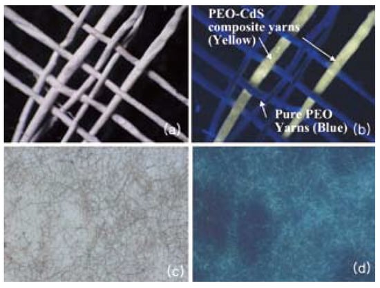
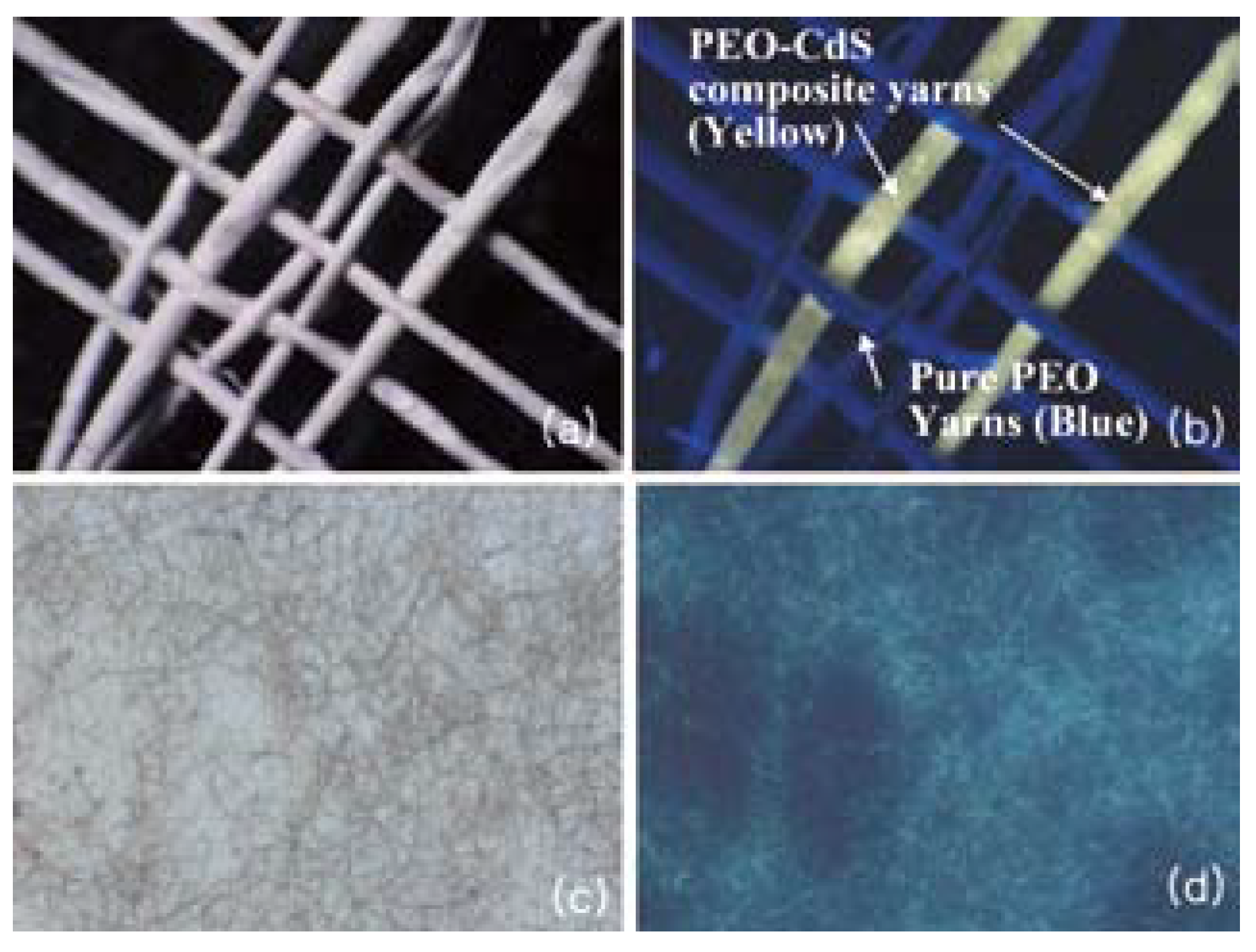
The optical microscopy and naked eye examination under UV lamp of electrospun nanofibres proved that the fluorescence properties of CdS are intact and one can use this technique for variety of applications. The electrospun fibres were processed into yarns then were woven as shown in Figure 11 A woven fabric consisting of PEO and PEO-CdS yarns was utilized to demonstrate the optical difference under naked eye. When this fabric was examined under a UV lamp, PEO-CdS composite yarns appeared distinctively yellowish in color while pure PEO yarns did not show any fluorescence. This could not be differentiated between yarns having PEO from the PEO-CdS composite yarns under normal light.
Figure 11.
Woven nanofibrous yarns that contain a mixture of PEO and PEO-CdS composite fibres. (a) Woven structure under normal light. (b) Woven structure under UV light. (c) Regular optical microscope and (d) Fluorecscence microscope image.
Magnetic Nanofibres - Magnetite (Fe3O4) is well known magnetic material for its ferromagnetic properties. This ferromagnetism is induced by the magnetic moment due to electron spin. In ferromagnetic materials, coupling interactions of neighboring atoms aligns atomic dipole with one another resulting in the permanent magnet without the influence of an external electrical field or magnetic field. For some solid materials, inherent magnetic moments are randomly oriented in the absence of external magnetic field but they align with external magnetic field. This phenomenon is called paramagnetism. Natural ferromagnetic material loses its atoms ordering at high temperature and shows paramagnetic behavior due to thermal energy. The family of magnetic nanoparticles can be synthesized through various chemical routes such as arc discharging or chemical precipitation [17].
When the diameters of ferromagnetic particles approach 100 nm or lower the ferromagnetic particles exhibit paramagnetic properties at room temperature. This phenomenon is referred to as superparamagnetic effect. In magnetic storage industry this thermal limit became a great challenge in fabricating high-density storage devices [30]. Typically these superparamegnetc particles exhibit a great susceptibility to external field making it suitable for various applications [31]. Magnetic nanoparticle composite fibre is also a good example of functional nanocomposite structure uniquely suitable for many applications such as EMI shielding, biomedical devices and sensors [32,33].
In this study, 20 wt% of PVDF-TeFE was dissolved into a mixture of Dimethylformadide and 2-Butane. 5 wt% and 10 wt% of dispersed 20~30nm Fe3O4 nanoparticles (purchased from Nanostructured & Amorphous Materials, Inc) were blended into the polymer solution for co-electrospinning. Various process parameters such as solution concentration, distance between target and nozzle and the effect of different types of solvent were evaluated in order to optimize the electrospinning process. The morphology, mechanical properties and the electrical property of nanocomposite were characterized.
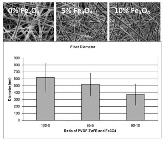
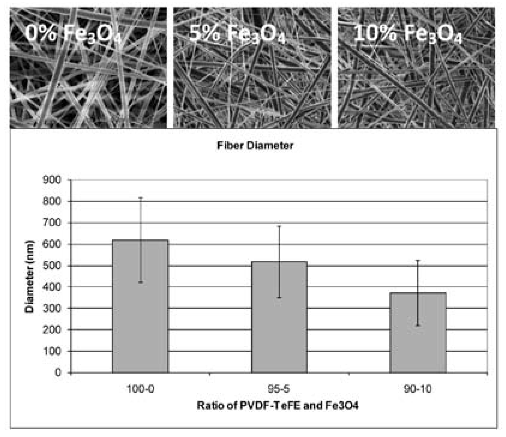
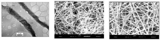
The diameter of electrospun fibres without magnetic particles was about 620 nm from 20 wt% of the solution. When Fe3O4 nanoparticles were added the average fibre diameters noticeably decreased to 515 nm and 370 nm for 5 % and 10 % by weight of loading and showed wide variation of fibre diameter as shown in Figure 12 This is also believed to be due to the changes in electrical properties and solution viscosity of the electrospinning dope.
Figure 12.
SEM of electrospun fibres from (a)20 wt% PVDF-TeFE solution (b) 20 wt% PVDF-TeFE with 5wt% Fe3O4, (c) 20 wt% PVDF-TeFE with 10wt% Fe3O4.
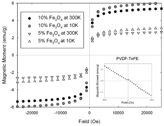
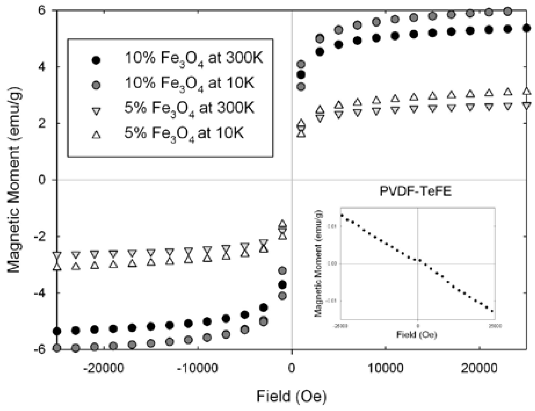
The magnetic properties of PVDF-TeFE and PVDF-TeFE/Fe3O4 composites were measured using a SQUID (Superconducting Quantum Interference Devices) magnetometer (Quantum Design, MPMS2). The applied external field was from -25K to 25K Oersted (Oe) at the temperature of 10K and 300K. The measured magnetic moment (emu) of the samples loaded with 5 wt % and 10 wt % of Fe3O4 were plotted in Figure 13 Paramagnetic properties were observed from Fe3O4 loaded PVDF-TeFE composite fibres while pure PVDF-TeFE showed typical diamagnetic property. As expected, the composite fibres containing 20~30 nm Fe3O4 particles exhibited superparamagnetic properties. Extremely high susceptibility to external magnetic field was shown regardless of particle contents in the composite fibres. The magnetic moment had a tendency to be saturated at 10K Oe and completely saturated about 20K Oe. At low temperature, both samples showed slightly higher magnetic moment than that of room temperature. Weak magnetization was observed from all samples under the magnetic field at 10K. When 5 wt % Fe3O4 was added, the magnetic moment was half of 10 wt % Fe3O4 sample. This linear behavior was observed for all temperatures.
Figure 13.
Magnetic moment of iron oxide nanopartcles embedded nanofibre.
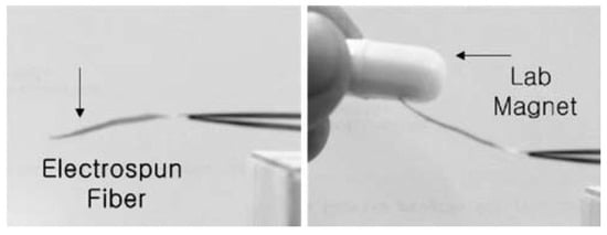
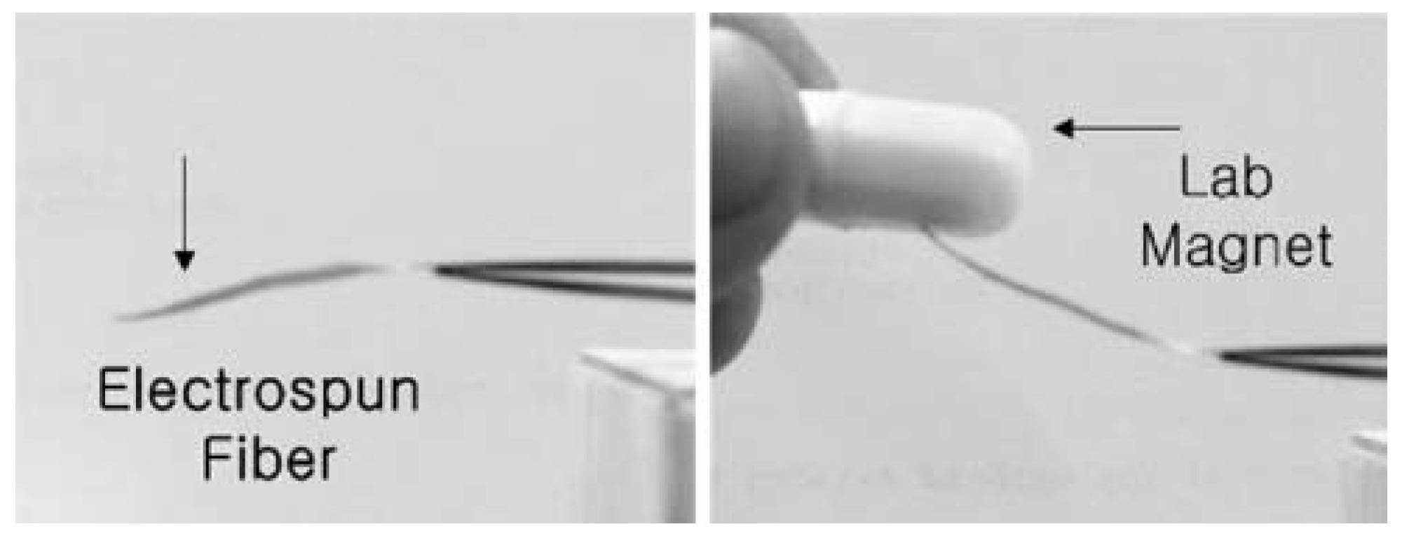
This strong field responsive behavior of electrospun magnetic composite mats to external magnetic field was demonstrated in Figure 14 A 2 cm strip of 5 wt% Fe3O4 loaded PVDF-TeFE was fixed at one end and the other end was allowed to move freely. When the composite fibre mat was exposed to external magnetic field induced by a simple laboratory magnet, the flexible mat was deformed toward the magnet as the magnet moved closer to the composite fibre bundle. It was showed that the sample was flexible and field responsive.
Figure 14.
Response of Electrospun Composite Fibre to External Magnetic Field.
Multifunctional Scaffold- An excellent illustration of the application of functional nanofibre is in our program to develop fibrous scaffold for cartilage regeneration. The un-mineralized collagen fibrils in the developing surfaces of bone give rise to mechanoelectrical effect that takes part in bone remodeling during growth and physiological healing process. In cartilage tissue engineering, it would be desirable to have a multifunctional composite scaffold system that provides not only tailorable structural reinforcement but also adjustable level of electrical conductivity. Research in our laboratory showed that nanofibre scaffold help facilitate organized cell migration and proliferation. [4,34]. Supronowicz etal [35] showed that bulk polylactic acid (PLA) polymer composite sheet containing CNT, when exposed to electric stimulation, promotes the cellular proliferation by several folds. In this study, we tested our hypothesis that the introduction of the carbon nanotube in a continous nanofilamentous matrix will create a multifunctional fibrous media to carry specific functions favorable for cell adhesion and cell growth while maintaining sufficient level of structural integrity.
Single wall carbon nanotube (SWNT) produced by the High-Pressure CO Conversion (HiPCO) process were dispersed in PLA- matrix and coelectrospun to form nanocomposite fibrous assemblies in linear, planar and three-dimensional structures. The morphology; electrical properties; mechanical properties; and cell-scaffold interactions were examined by TEM, SEM, AFM, Raman spectroscopy; four probe electrical conductivity, micro-tensile testing, and various biological assays.
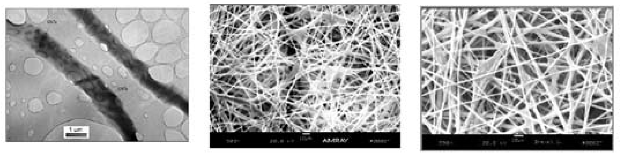
TEM, SEM, Raman spectroscopy verified the successful introduction of CNT in nanocomposite fibrils. Figure 15 a,b,c. illustrate the TEM image showing the CNT in PLA matrix (a) and SEM image (b)of chondrocyte adhesion and migration (c). With the introduction of 5 wt % of CNT four probe test showed a two-order increase in conductivity (1.3x10⁻⁴ vs. 2.4x10⁻² S/cm); and tensile modulus from 0.5 - 100 MPa was achieved compared to pure PLA. Table 2 provides a summary the increase in mechanical and electrical properties by the introduction of various wt% of carbon nanotubes.
Figure 15.
TEM (a) and SEM (b) images of carbon nanotube reinforced PLA nanofibres, (c) cell growth in CNT/PLA scaffold (Left to right a, b, c).
Table 2.
The effect of carbon nanotube on the mechanical and electrical properties of PLA scaffold.
The scaffold also produced interconnected pores with a wide range of diameter, optimum for cell migration and transport of nutrients. Changing the conditions during electrospinning can control both porosity and pore size. The highly porous scaffold acts as a negative template for the cartilage. Systematic evaluation of the scaffold indicates that it has an optimized structure of a cartilage cell growth and the mechanical property of the scaffold is in the range of the modulus of the cartilage at physiological state. The electrical conductivity of the scaffold is expected to stimulate cell growth.
The in vitro study showed that the nanofibrenanotube scaffold allows cell growth and proliferation without detrimental effect due to the presence of nanotubes. Hence, it can be concluded at least at this preliminary study that the CNT inside nanofibres are “cell friendly”. The Raman spectroscopy shows convincing evidence of the presence of nanotubes with the display of typical spectra for CNTs. TEM study serves as the visual evidence for the presence of the nanotubes by the lattice fringe of the CNT crystals in the form of ropes and onions. Lower magnification TEM images also confirm the alignment of the SWNTs along the length of the nanofibre. Both SEM images of the polymer fibre mat and AFM images of a single nanofibre show surface roughness in the CNT containing fibres. There is increase in the roughness with the increased percentage of nanotubes. On the other hand, the fibres without nanotubes have a very plain surface morphology. In vitro evaluation on nanofibre-nanotube scaffold showed that, chondrocytes proliferate rapidly over the surface and as well as migrating to the deeper part of the matrix through the porous system. The cellular behavior was characterized by the cell attachment, cell spreading and morphology of the cells by producing the cytoplasmic extensions. Correct morphology of the chondrocytes seeded on the scaffold, secretion of cell-specific procollagen II indicates that the cells function correctly within the scaffold. In addition, the intercellular bridging among the interconnected pores of the multiple layered nanofibre fabric allows formation of threedimensional cellular network at nano level.
3. Conclusions and Future Direction
In the evolution of material development we have reached the era of functional nanofibers. Nanoparticlular materials in various geometries and shapes possess outstanding functions unavailable in bulk materials. By combining the functional nanoparticles with a polymer matrix and forming composite nanofibres using the coelectrospinning process a processing pathway is now available, enabling the connection of the functional nanoparticle to higher order structures such as yarn, fabric, composites and products.
Experimental evidence shows that the nanoeffects of the nanoparticles can be transferred to fibrous assemblies thus opening up exciting design options for the next generation of high performance sportswear and advanced medical devices.
The exciting new opportunities with the enabling nanofibrous materials also will bring about new challenges in quality control and scaleability of process. There is a need for standardization of characterization method for these new materials and new performance properties.
The question is how will this new nanofibre technology impact the fibre-textile-finishing-garmentretailing complex and how do we capitalize on the opportunities created by the functional fibre technology?
Acknowledgments
The results generated in this paper are supported in part by the Natural Sciences and Engineering Research Council of Canada (NSERC) and CFI funding for equipment development. Additional support also received from the AFOSR-AOARD.
References
- McQuaid, M. Extreme textiles: Design for high performance; Smithsonian Cooper-Hewitt, National Design Museum, Princeton Architectural Press, 2005. [Google Scholar]
- Beyond fibres. National museum of emerging science and innovation (MeSci). 2004.
- Wang, Z.L.; Kang, Z.C. Functional and smart materials. Structural evolution and structure analysis, 1st ed.; Springer, 1998. [Google Scholar]
- Ko, F.K.; Laurencin, C.T.; Borden, M.D.; Reneker, D.H. Proceedings. Annual Meeting; Biomaterials Research Society, 1998. [Google Scholar]
- Norris, I.D.; Shaker, M.M.; Ko, K.; MacDiarmid, A.G. Synth. Met. 2000, 114, 109–114.
- Nabet, B.; Castro, F.; Anwar, A.; Cola, A. Heterodimensional contacts and optical detectors. Int. J. High Speed Electron. Syst. 2000, 10, 375386. [Google Scholar] [CrossRef]
- Ko, F.K.; Aufy, A.; Lam, H.; MacDiarmid, A. Wearable electronics; Tao, X.M., Ed.; Woodhead, 2005. [Google Scholar]
- Gordon, J.E. The new science of strong materials; Princeton, 1984. [Google Scholar]
- Dresslhaus, M.S.; Dresslhaus, G.; Avouris, P.H. (Eds.) Carbon Nanotubes; Springer, 2000. [Google Scholar]
- Reneker, D.H.; Iksoo, C. Nanometre diameter fibres of polymer produced by electrospinning. Nanotechnology 1996, 7, 216–223. [Google Scholar] [CrossRef] [Scilit]
- Formhals, A. US Patent No. 1975504, 1934.
- Doshi, J.; Reneker, D.H. Electrospinning process and applications of electrospun fibres. J. Electrostat 1995, 35, 151–160. [Google Scholar] [CrossRef] [Scilit]
- Gibson, P.W.; Schreuder-Gibson, H.L.; Riven, D. Electrospun fiber mats. Transport properties. AICHE J. 1999, 45, 190–195. [Google Scholar] [CrossRef] [Scilit]
- Rutledge, G.; Fridrikh, S.; et al. Electrostatic production of nanofibers control of the fiber diameter. Texcomp 2002, 6. [Google Scholar]
- Hager, B.L.; Berry, G.C. Moderately concentrated solutions of polystyrene. I. Viscosity as a function of concentration, temperature, and molecular weight. J. Polym. Sci. Polym. Phys. 1982, 20, 911–928. [Google Scholar] [CrossRef] [Scilit]
- Yamashita, Y. 山下義裕. Electrospinning ”エレクトロスピニング最前線-ナノファイバー創製への挑戦-”; 繊維社, 2007. [Google Scholar]
- Lee, J.; Isobe, T.; Senna, M. Preparation of ultrafine Fe3O4 particles by precipitation in the presence of PVA at high pH. J. Colloid Interf. Sci. 1996, 177, 490–494. [Google Scholar] [CrossRef] [Scilit]
- Qi, L.; Cölfen, H.; Antonietti, M. Synthesis and characterization of CDS nanoparticles stabilized by double-hydrophilic block copolymers. Nano Lett. 2001, 1, 61–65. [Google Scholar] [CrossRef] [Scilit]
- Murray, C.B.; Kagan, C.R.; Bawendi, M.G. Synthesis and characterization of monodisperse nanocrystals and close-packed nanocrystal assemblies. Annu Rev. Mater. Sci. 2000, 30, 545–610. [Google Scholar] [CrossRef] [Scilit]
- Trapalis, C.C.; Keivanidis, P.; Kordas, G.; Zaharescu, M.; Crisan, M.; Szatvanyi, A.; Gartner, M. TiO2(Fe3+) nanostructured thin films with antibacterial properties. Thin Solid Films 2003, 433, 186–190. [Google Scholar] [CrossRef] [Scilit]
- Ko, F.K.; Gogotsi, Y.; Ali, A.; Naguib, N.; Ye, H.; Yang, G.L.; Li, C.; Willis, P. Electrospinning of continuous carbon nanotube-filled nanofibre yarns. Adv. Mater. 2003, 15, 1161–1165. [Google Scholar] [CrossRef] [Scilit]
- Inoue, T.; Dillon, D.; Li, C.Y.; Ko, F.K. Proceedings of the 33rd Textile Research Symposium, Mt. Fuji. 2004.
- Goto, T.; Ono, Y.; Kotaki, M.; Ko, F.K. Proceedings of the seventh joint Canada-Japan workshop on composites. 2008.
- Ko, F.K.; Yang, H.; Argawal, R.; Katz, H. Texhtextil, Atlanta. 2004.
- Yang, H.J.; Ko, F.K. Proceedings of the seventh joint Canada-Japan workshop on composites. 2008.
- Brus, L.E. Electron-electron and electron-hole interactions in small semiconductor crystallites. The size dependence of the lowest excited electronic state. J. Chem. Phys. 1984, 80, 4403–4409. [Google Scholar] [CrossRef] [Scilit]
- Chan, W.C.W.; Maxwell, D.J.; Gao, X.; Bailey, R.E.; Han, M.; Nie, S. Luminescent quantum dots for multiplexed biological detection and imaging. Curr. Opin. Biotech 2002, 13, 40–46. [Google Scholar] [CrossRef] [Scilit] [PubMed]
- Chen, Y.; Rosenzweig, Z. Luminescent CdS quantum dots as selective ion probes. Anal. Chem. 2002, 74, 5132–5138. [Google Scholar] [CrossRef] [Scilit] [PubMed]
- Shih, W.H.; Shih, W.Y.; Li, H.; Schillo, M.C. Synthesis of water soluble nanocrystalline quantum dots and uses thereof. US Patent No.20060078490, 2006. [Google Scholar]
- Weller, D.; Moser, A. Thermal effect limits in ultrahigh-density magnetic recording. IEEE T Magn. 1999, 35, 4423–4439. [Google Scholar] [CrossRef] [Scilit]
- Wang, M.; Singh, H.; Hatton, T.A.; Rutledge, G.C. Fieldresponsive superparamagnetic composite nanofibres by electrospinning. Polymer 2004, 45, 5505–5514. [Google Scholar] [CrossRef] [Scilit]
- Tan, S.T.; Wendorff, J.H.; Pietzonka, C.; Hong, Z.; Gui, J.; Wang, Q. Biocompatible and biodegradable polymer nanofibres displaying superparamagnetic properties. Chem. Phys. Chem. 2005, 6, 1461–1465. [Google Scholar] [CrossRef] [Scilit] [PubMed]
- Mornet, S.; Vasseur, S.; Grasset, F.; Duguet, E. Magnetic nanoparticle design for medical diagnosis and therapy. J. Mater. Chem. 2004, 14, 2161–2175. [Google Scholar] [CrossRef] [Scilit]
- Li, W.J.; Laurencin, C.T.; Caterson, E.J.; Tuan, R.S.; Ko, F.K. Electrospun nanofibre structure: A novel scaffold for tissue engineering. J. BioMed Mater. Res. 2002, 60, 613621. [Google Scholar] [CrossRef] [Scilit] [PubMed]
- Supronowicz, P.R.; Ajayan, P.M.; Ullmann, K.R.; Arulanandam; Metzger, D.W.; Bizios, R. Novel current conducting composite substrate for exposing osteoblasts to alternating current stimulation. J. BioMed Mater. Res. 2002, 49, 499–506. [Google Scholar] [CrossRef] [Scilit] [PubMed]

© 2008 Textile Bioengineering and Informatics Society. This article is an open access article distributed under the terms and conditions of the Creative Commons Attribution (CC BY) license (https://creativecommons.org/licenses/by/4.0/).