


Abstract
This study presents a comprehensive non-invasive technical investigation of The Penitent Magdalene from the former Joseph Robinson Collection, a painting traditionally attributed to Anthony van Dyck rather than Peter Paul Rubens. High-resolution imaging, digital microscopy, ultraviolet fluorescence, infrared reflectography, X-radiography, macroscopic X-ray fluorescence mapping, and reflectance imaging spectroscopy were used to examine its materials, technique, and conservation history. The results reveal seventeenth-century materials and painting practices consistent with both Rubens and Van Dyck, together with extensive compositional revisions and painting techniques showing close affinities with Rubens and his workshop. Comparison with Titian’s Penitent Magdalene and Cornelis Cort’s engraving further demonstrates strong compositional relationships. The combined technical and art-historical evidence suggests that the long-standing preference for a Van Dyck attribution should be reconsidered and that Rubens deserves renewed consideration as a possible author.
1. Introduction
1.1. Background
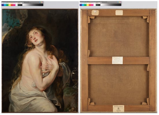
The attribution of The Penitent Magdalene from the former Joseph Robinson Collection (Figure 1) [1], hereafter referred to as the Tokyo painting, has long been the subject of scholarly debate, particularly regarding whether the work should be attributed to Peter Paul Rubens or Anthony van Dyck [2,3].
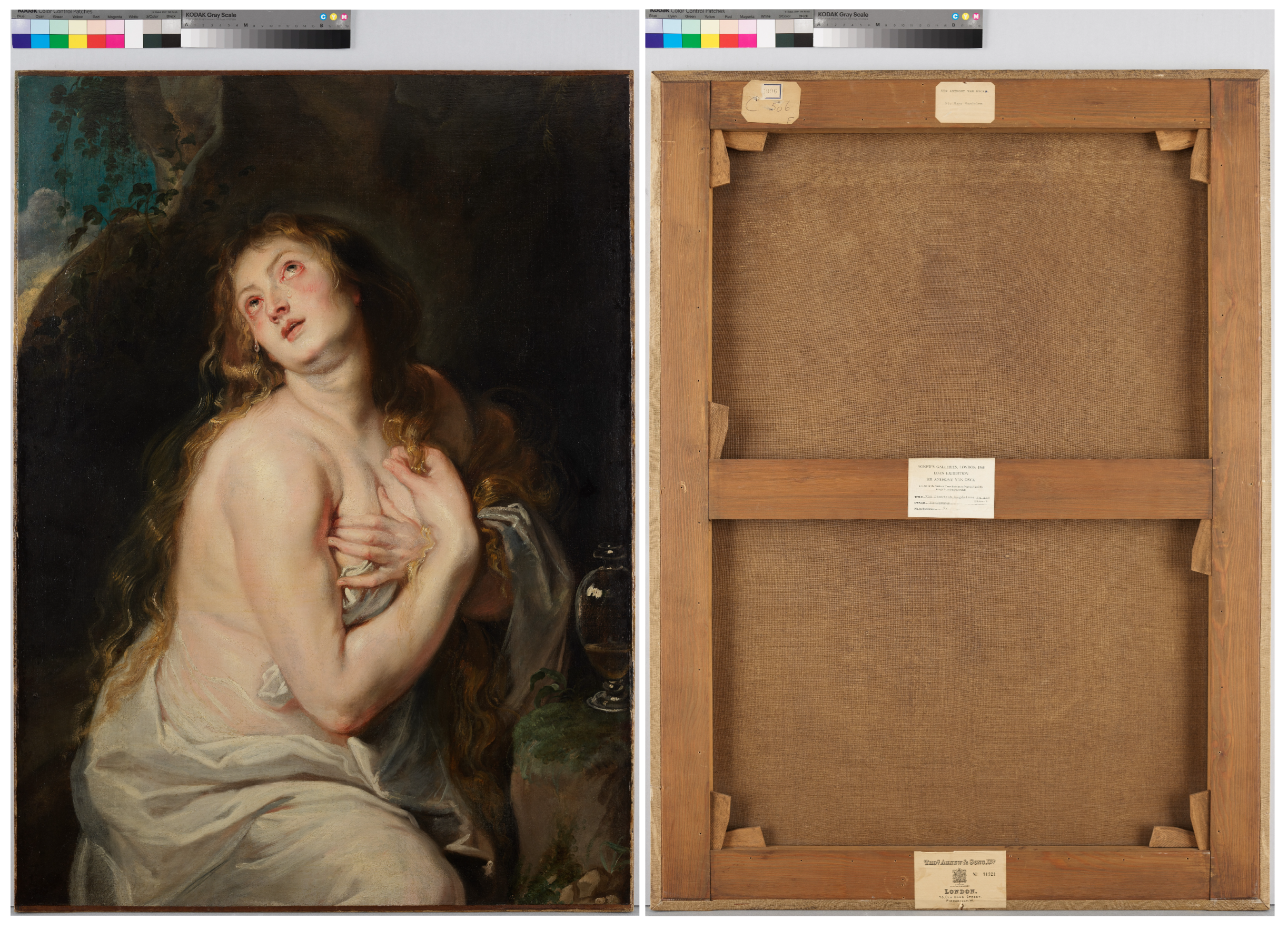
Figure 1.
The Penitent Magdalene, c. 1618–1620, oil on canvas, 99.6 × 73.2 cm. (Left): overall visible-light image of the painting. (Right): reverse showing the stretcher and collection labels.
Both artists played a central role in the development of seventeenth-century Flemish painting, and the resolution of this question bears important implications for our understanding of workshop practice, artistic transmission, and the emergence of early Baroque painting in Antwerp. Despite sustained art-historical discussion, direct scholarly access to this painting has been extremely limited. Since its arrival in Japan in the late 1960s, it has rarely been exhibited [4], and previous studies have therefore relied largely on stylistic comparison and documentary evidence. Although these studies have provided valuable insights, the lack of comprehensive technical data has prevented an objective assessment of the painting’s materials, technique, conservation history, and ultimately its attribution.
In recent decades, advances in non-invasive imaging and analytical technologies have greatly expanded the possibilities for technical art-historical research. Multimodal approaches integrating macroscopic X-ray fluorescence, reflectance imaging spectroscopy, infrared reflectography, and X-radiography now enable detailed investigation of material composition, paint stratigraphy, and artistic working processes without destructive sampling [5,6,7,8]. Such methods have become increasingly important in the study of complex attribution problems. At the same time, it has long been recognized that analytical technologies alone cannot resolve questions of authorship or artistic practice. As Murray Pease observed, “scientific examination is essentially an activity of the mind rather than merely the use of instruments,” emphasizing that technical evidence must ultimately be interpreted through informed historical and stylistic analysis [9]. The integration of scientific investigation with art-historical inquiry is therefore essential for addressing complex questions of attribution.
1.2. Previous Studies
Several scholarly publications have addressed the attribution of the Tokyo painting. In the exhibition catalog accompanying the 1968 Van Dyck exhibition at Agnew’s Gallery, Jullian Agnew [1] classified the work as an authentic painting by Anthony van Dyck. In the same year, Oliver Miller [10] questioned this attribution, stating that the composition and handling were not characteristic of Van Dyck, although he did not propose an alternative attribution.
Müller Hofstede [11] subsequently attributed the painting to Peter Paul Rubens, dating it to c. 1618–1620. He argued that the composition is closely related to Rubens’s Mary and Jesus with St John, Worshipped by Repentant Sinners and Saints in the Museumslandschaft Hessen Kassel, particularly in the nearly identical treatment of the Magdalene’s arms, which he considered to derive from the same preparatory study. He also noted that Michael Jaffé [12], by contrast, supported an attribution to Van Dyck.
The most recent catalog raisonné of Van Dyck, published by Barnes, De Poorter, Miller, and Vey in 2004 [13], does not include the Tokyo painting. Nakamura [2] suggested that this decision may have reflected Miller’s earlier skepticism.
Following a firsthand examination of the painting in 2012, Nakamura [2] concluded that, although the work exhibits strong Rubensian characteristics, it also contains key stylistic features typical of Van Dyck and should therefore be attributed to Van Dyck rather than Rubens. He proposed a date of c. 1617–1618, immediately preceding the execution of the Kassel painting. Nakamura also noted that only a limited number of scholars—including Oliver Miller, Michael Jaffé, and Müller Hofstede—had examined the painting directly. In a subsequent study, Nakamura [3] further suggested that Müller Hofstede may not have inspected the painting firsthand before publishing his 1983 study, reaffirmed the attribution to Van Dyck, and revised the proposed date to c. 1618–1620.
In summary, the Tokyo painting has remained the subject of divergent scholarly opinions. Müller Hofstede attributed the work to Rubens, whereas Agnew, Jaffé, and Nakamura supported an attribution to Van Dyck, while Miller expressed reservations without proposing an alternative attribution. Given that very few specialists have examined the painting directly, previous studies have relied largely on stylistic interpretation, underscoring the need for a comprehensive technical investigation.
1.3. Aim of the Present Study
The present study applies an integrated, non-invasive analytical approach to the Tokyo painting in order to establish an objective body of technical evidence concerning its materials, painting techniques, execution, and conservation history. Building upon this evidence, the study reassesses the painting’s attribution through comparison with works associated with Peter Paul Rubens, Anthony van Dyck, and Titian, with particular attention to whether the long-standing preference for a Van Dyck attribution remains justified in light of the newly obtained technical findings.
2. Material and Methods
2.1. The Painting Investigated and Reference Pigments
The object of this investigation is The Penitent Magdalene, formerly in the Joseph Robinson Collection and currently in a private collection in Japan (Figure 1 Left). The painting depicts the Penitent Magdalene in a rocky landscape. She is shown gazing upward, with an ointment jar placed beside her right hand, reflecting the traditional iconography of the penitent saint. The painting is executed in oil on canvas and measures 99.6 × 73.2 cm and has traditionally been attributed to Anthony van Dyck.
The reverse of the stretcher bears five adhesive labels are present on the reverse of the stretcher. Along the upper edge, a label printed “□9961” is affixed over another bearing the inscription “C 506 F,” together with a label reading “SIR ANTHONY VAN DYCK□. St. Mary Magdalene.” At the center is a label from “AGNEW’S GALLERIES, LONDON 1968 LOAN EXHIBITION SIR ANTHONY VAN DYCK”, identifying the painting as The Penitent Magdalene in the Desert. Along the lower edge is a label printed “No. 31321” bearing the name “THOS AGNEW & SONS LTD.” (Figure 1 Right). The work has undergone several restoration campaigns, and localized paint losses and retouchings are visible.
2.2. Reference Pigments
To facilitate the interpretation of the RIS data, a set of reference pigment standards was employed. The pigments and their suppliers are summarized in Table 1. These standards were selected to represent pigments commonly encountered in seventeenth-century Flemish paintings and were used as reference materials for comparison with the measured reflectance spectra, in conjunction with the elemental information obtained by MA-XRF.
Table 1.
The reference pigments used for spectral comparison and their suppliers.
No paint mock-ups were prepared for the reference measurements. To eliminate any spectral influence from a binding medium or preparation layer, each reference pigment was measured directly in its powdered form after being spread evenly on weighing paper. Reference mixtures representing flesh tones were likewise prepared by mixing the pigments in powder form only, without the addition of a binding medium. These mixtures consisted of lead white with a small amount of either vermilion or red lead. The proportions were adjusted visually so that the resulting color approximated the flesh tones observed in the painting, rather than according to predetermined mixing ratios.
2.3. High-Resolution Visible-Light Imaging (VIS)
High-resolution visible-light images of the painting were acquired using a Phase One IQ3 100MP Trichromatic digital back (Phase One A/S, Copenhagen, Denmark), while a Hasselblad H5D-200MS medium-format camera (Hasselblad, Gothenburg, Sweden) was employed in multi-shot mode to produce a composite image of approximately 200 megapixels, thereby providing enhanced spatial resolution and colour fidelity for detailed technical examination.
2.4. Ultraviolet-Induced Visible Fluorescence Imaging (UVF)
Ultraviolet-induced visible fluorescence (UVF) imaging was performed using a Hasselblad H5D-200MS digital camera (Hasselblad, Gothenburg, Sweden). The painting was illuminated with four HITACHI Black Light FL40S-BL-B ultraviolet lamps (Hitachi, Tokyo, Japan; λmax = 352 nm). To ensure that only visible fluorescence was recorded, the camera lens was fitted with a KODAK Wratten 2E optical filter (Eastman Kodak Company, Rochester, NY, USA), which effectively blocks ultraviolet radiation while transmitting visible wavelengths.
2.5. Near-Infrared Reflectography (IRR)
Infrared reflectograms were acquired using a Hamamatsu Photonics C12741-03 InGaAs camera (Hamamatsu Photonics K.K., Hamamatsu, Japan), equipped with an InGaAs sensor sensitive to wavelengths in the 950–1700 nm range and providing a spatial resolution of 640 × 512 pixels. Imaging was conducted at a camera-to-object distance of 150 cm using a 50 mm focal-length lens set to f/4. Illumination was supplied by two 750 W tungsten–halogen lamps (Lowel Tota-Light; Lowel-Light Manufacturing, Brooklyn, NY, USA. A long-pass filter (Thorlabs FELH1500; Thorlabs, Newton, NJ, USA) was mounted in front of the lens to block wavelengths below 1500 nm, thereby enhancing the visibility of subsurface features. The IRR image was acquired by dividing the painting surface into eight overlapping areas. Adjacent images were captured with approximately 20% overlap of the field of view to facilitate accurate image registration. The individual images were automatically mosaicked using Microsoft Image Composite Editor ver.1.4.4.0 (Microsoft Corporation, Redmond, WA, USA), which aligned the images based on feature matching to generate the final composite IRR image.
2.6. X-Ray Radiography (XRR)
X-radiographic imaging was performed using a GE ERESCO 42 portable X-ray unit equipped with a 200 kV directional X-ray tube (GE Sensing & Inspection Technologies, Wunstorf, Germany). Soft X-radiation suitable for the examination of paintings was generated using operating parameters of 40 kV, 2.5 mA, and an exposure time of 10 s. The radiographs were recorded on phosphor imaging plates (356 × 432 mm) and digitized using a GE CR Flex computed radiography system (GE Healthcare, Chalfont St Giles, UK). Since a single imaging plate was insufficient to cover the entire painting, the XRR image was acquired through 15 partially overlapping exposures. Adjacent images were captured with approximately 20% overlap to ensure accurate registration. The individual XRR images were automatically stitched using Microsoft Image Composite Editor ver.1.4.4.0 (Microsoft Research, Redmond, WA, USA), which aligned the images based on feature matching to generate the final composite radiograph. The resulting high-resolution X-radiographs enabled examination of the painting’s internal structure, including the support, ground layers, and evidence of compositional changes.
2.7. Macroscopic X-Ray Fluorescence Scanning (MA-XRF)
Macroscopic X-ray fluorescence (MA-XRF) mapping [14,15,16] was carried out using a Bruker M6 Jetstream large-area scanning system (Bruker Nano Analytics, Berlin, Germany). The instrument is equipped with a rhodium-target microfocus X-ray tube operated at 50 kV and 399 μA, coupled with dual 60 mm2 silicon drift detectors. The measuring head is mounted on an XY-motorized stage with a maximum travel range of 80 × 60 cm, allowing positional steps as small as 10 μm. Measurements were conducted with a 350 μm beam spot size and a pixel dwell time of 20 ms. All scans were performed in open-air conditions, yielding qualitative elemental distribution data for elements with atomic numbers Z ≥ 15 (phosphorus and above). The acquired XRF spectra were processed, deconvoluted, and evaluated using the Bruker M6 Jetstream software, which generated the elemental distribution maps used in this study. Due to the limited travel range of the measuring head, the painting was scanned in two separate acquisitions (upper and lower), and the resulting MA-XRF datasets were digitally merged to produce a single composite elemental distribution map.
2.8. Reflectance Imaging Spectroscopy (RIS)
Reflectance Imaging Spectroscopy (RIS) measurements [7,8,16,17] were conducted using two pushbroom-type hyperspectral cameras (ClydeHSI VNIR-HR and NIR-HR+; ClydeHSI, Glasgow, UK), operating respectively in the visible–near-infrared (VNIR-HR, 400–1000 nm) and near-infrared (NIR-HR+, 900–1700 nm) spectral ranges. Both cameras were mounted on a single pan–tilt scanning unit, allowing coordinated and sequential acquisition with identical geometric alignment. To achieve high spatial resolution across the entire surface, the painting was divided into eight scanning zones. For each zone, the easel was repositioned vertically and horizontally, and the painting was also inverted to optimize the scanning geometry. Within each zone, image acquisition was carried out by the tilt-axis motion of the scanner. The working distance between the cameras and the painting was fixed at 900 mm. The principal imaging parameters for the VNIR-HR and NIR-HR+ systems are summarized in Table 2.
Table 2.
Principal acquisition parameters of the VNIR-HR and NIR-HR+ hyperspectral imaging systems used for reflectance imaging spectroscopy (RIS).
All acquired hyperspectral data cubes were processed using Clyde SpectraSENS (ClydeHSI, Glasgow, UK). A Teflon reference target (Misumi) of sufficient length was positioned adjacent to the painting to obtain reflectance standards under identical geometric and illumination conditions. Reflectance reference data were collected using the same exposure settings as the sample measurements. Dark-field data were acquired by closing the camera shutter to eliminate incident light. The spectral cubes were subsequently corrected using both the reflectance reference and dark-field measurements to produce calibrated reflectance data.
2.9. Digital Microscopy Imaging (DMI)
Digital microscopy was performed to examine the surface morphology, paint layer structure, and micro-features of the work. Observations were carried out using a Hirox HRX-02 digital microscope equipped with a 2/3-inch, 5.07-megapixel CMOS image sensor (Hirox Co., Ltd., Tokyo, Japan), allowing high-resolution imaging across a wide magnification range. The microscope was fitted with a HR-1020E high-resolution telecentric motorized zoom lens (Hirox Co., Ltd., Tokyo, Japan), providing a continuous magnification range of 10× to 200× with a fixed working distance of 54 mm. The telecentric optical design ensured minimal distortion and constant image scaling across the entire field of view, which was essential for accurate documentation of micro-structural features such as pigment particle morphology, craquelure development, and retouching boundaries. The motorized zoom mechanism enabled precise and repeatable control of magnification during consecutive imaging sessions.
3. Results
This section presents the principal observational results that provide the basis for the technical examination of the painting. Representative digital microscopy images and RIS reflectance spectra have been transferred to the Supplementary Materials. The main text retains the primary imaging datasets and selected comparative figures that are repeatedly referred to throughout the discussion, including visible-light photography, UV-induced visible fluorescence (UVF), infrared reflectography (IRR), X-radiography (XRR), MA-XRF elemental maps, and enlarged regions of interest where appropriate. These observations are presented without extensive interpretation, which is developed in Section 4 through the integrated evaluation of the complementary datasets to investigate the painting’s materials, painting technique, conservation history, and attribution.
3.1. VIS, UVF, IRR, XRR
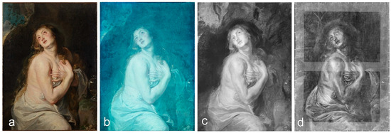
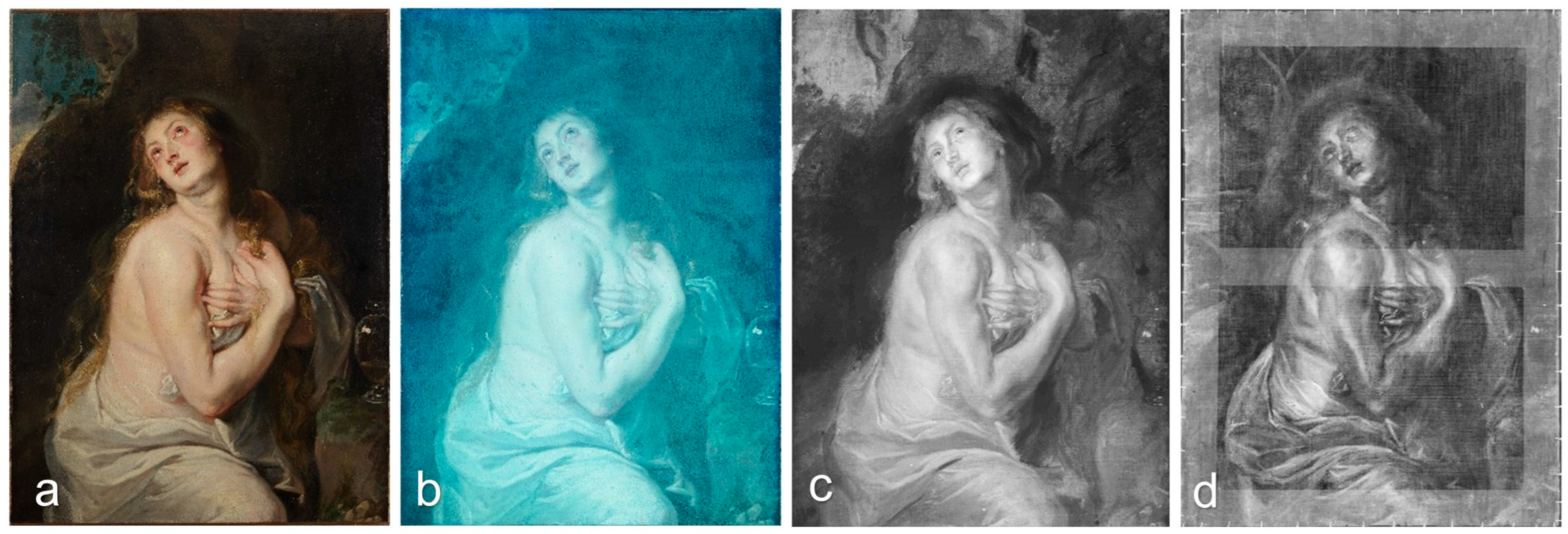
Representative visible-light (VIS), ultraviolet-induced visible fluorescence (UVF), infrared reflectography (IRR), and X-radiography (XRR) images are presented in Figure 2. These images constitute the primary observational dataset used for the subsequent interpretation presented in Section 4.
Figure 2.
Visible-light image (a); ultraviolet-induced visible fluorescence (UVF) image (b); near-infrared reflectography (IRR) image (c); and X-ray radiograph (XRR) (d).
3.2. MA-XRF
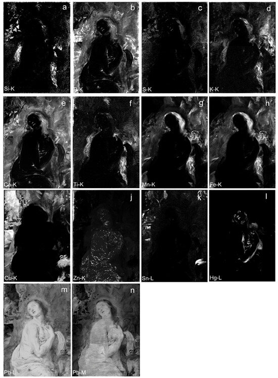
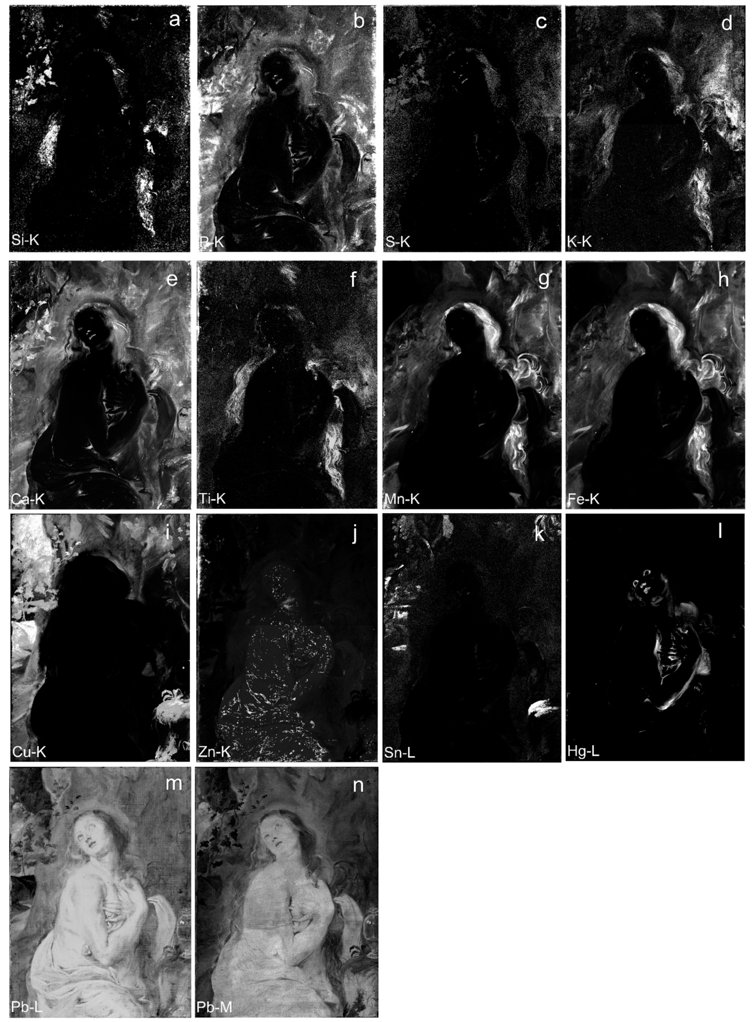
Representative MA-XRF elemental distribution maps are presented in Figure 3. These elemental maps constitute the primary analytical dataset used for the subsequent interpretation discussed in Section 4.
Figure 3.
Complete set of MA-XRF elemental maps acquired from the painting. (a) Si-Kα map. (b) P-Kα. (c) S-Kα. (d) K-Kα. (e) Ca-Kα. (f) Ti-Kα. (g) Mn-Kα. (h) Fe-Kα. (i) Cu-Kα. (j) Zn-Kα. (k) Sn-Lα. (l) Hg-Lα. (m) Pb-Lβ. (n) Pb-Mα. These images constitute the primary dataset from which the detailed interpretations presented in Section 4 are derived. Unless otherwise indicated, brighter (white) regions represent higher elemental intensity, whereas darker (black) regions represent lower elemental intensity.
3.3. DMI
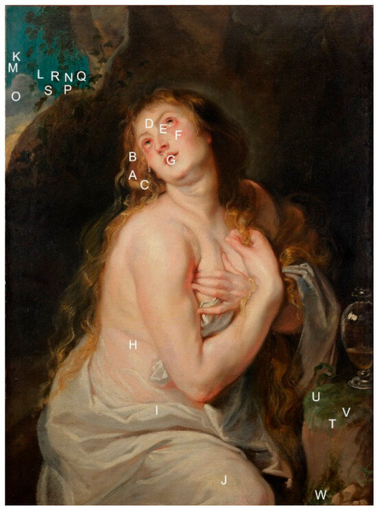
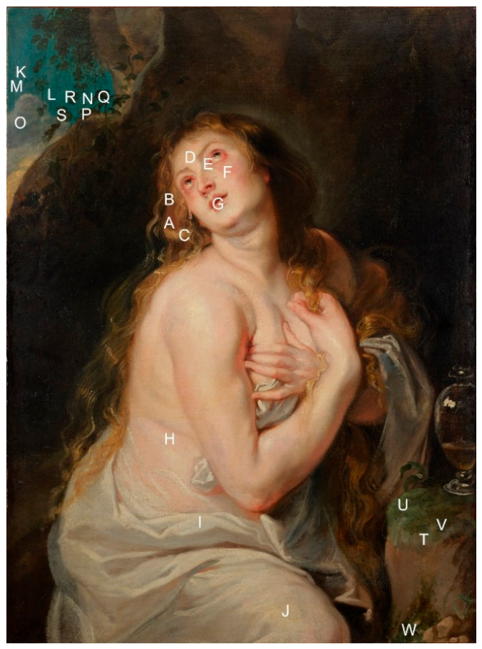
Representative digital microscopy images are provided in Supplementary Materials, and the corresponding observation locations are indicated in Figure 4. The complete digital microscopy dataset is presented in the Supplementary Materials, while representative images directly relevant to the interpretation are referred to in Section 4.
Figure 4.
Locations of representative areas examined by DMI and RIS analysis, indicated by uppercase letters: hair (A–C), flesh tones (D–H), drapery (I,J), the blue sky (K–O), plant leaves in the upper-left corner (P–S), and vegetation growing on the rock beneath the ointment jar (T–W).
3.4. RIS
Representative reflectance spectra acquired by RIS are provided in the Supplementary Materials. The measurement locations are indicated in Figure 4, and the reference pigments used for spectral comparison are listed in Table 1. The complete spectral dataset is presented in the Supplementary Materials, while representative spectra directly relevant to the interpretation are discussed in Section 4.
4. Discussion
The present study provides the first comprehensive non-invasive technical investigation of the Tokyo painting, establishing an objective basis for discussing its materials, painting technique, conservation history, and attribution. Because the painting has remained largely inaccessible for technical examination, previous assessments relied primarily on stylistic analysis. The multimodal analytical results presented here therefore provide the first reproducible technical evidence for reassessing the painting.
Comparative evaluation with securely attributed works by Peter Paul Rubens and Anthony van Dyck is currently limited by the scarcity of published multimodal technical studies, particularly those including MA-XRF. Accordingly, the following discussion is based on the available published technical literature together with established knowledge of seventeenth-century Flemish painting practice.
4.1. Painting Technique
4.1.1. Canvas, Ground, Imprimatura and Varnish Layers
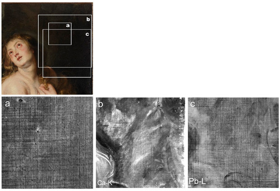
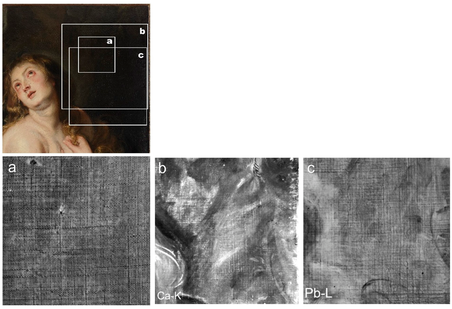
The stretcher measures 100.1 cm in height and 73.7 cm in width, with a thickness of approximately 2 cm and a width of about 7 cm (Figure 1). It was newly made during a previous treatment and is not original. The dimension of the canvas measure 99.6 cm in height, and 73.2 cm in width, reflecting slight irregularities. The original canvas is of plain weave, with a thread density of approximately 14 threads per centimeter in both warp and weft, showing minor local variations between 13 and 15 threads per centimeter. As it is backed, the original canvas cannot be observed from the reverse side; however, the thread density can be measured using XRR imaging (Figure 5a).
Figure 5.
Structure of the support, ground, and imprimatura layers. Top: Visible-light image of the region examined in panels (a–c). (a) XRR. (b) Ca-Kα map. (c) Pb-Lβ map.
MA-XRF mapping of Ca shows that the calcium distribution closely follows the weave pattern of the plain-woven canvas (Figure 5b), indicating that the calcium-bearing material is associated with the ground layer rather than with localized paint applications. This correspondence suggests that variations in ground thickness, resulting from irregularities in the canvas structure, are reflected in the Ca distribution. The widespread and homogeneous occurrence of calcium is therefore consistent with the use of a calcium-rich ground, most plausibly chalk, as commonly employed in seventeenth-century Flemish paintings. However, because MA-XRF provides elemental rather than molecular information, the calcium-bearing material cannot be identified unequivocally on the basis of elemental mapping alone. The RIS data do not provide diagnostic spectral features in the near-infrared region that would permit independent confirmation of chalk. Accordingly, the interpretation is based on the combined elemental distribution observed by MA-XRF together with the expected stratigraphic position of the ground layer and established historical painting practice. MA-XRF mapping reveals a distribution of Pb following the fabric’s weave texture, suggesting this is an imprimatura applied with lead white over a chalk ground (Figure 5c). The presence of the imprimatura layer throughout the entire surface, combined with the uniform distribution of Pb, suggests it was applied evenly using a brush moved in various directions [18]. This contrasts with the imprimatura seen in Rubens’ panel paintings, where it appears as parallel linear patterns [14,18,19].
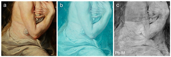
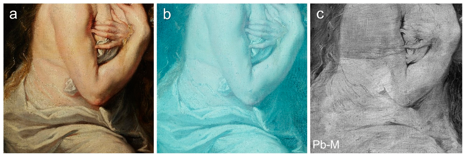
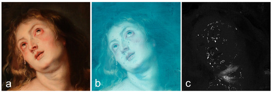
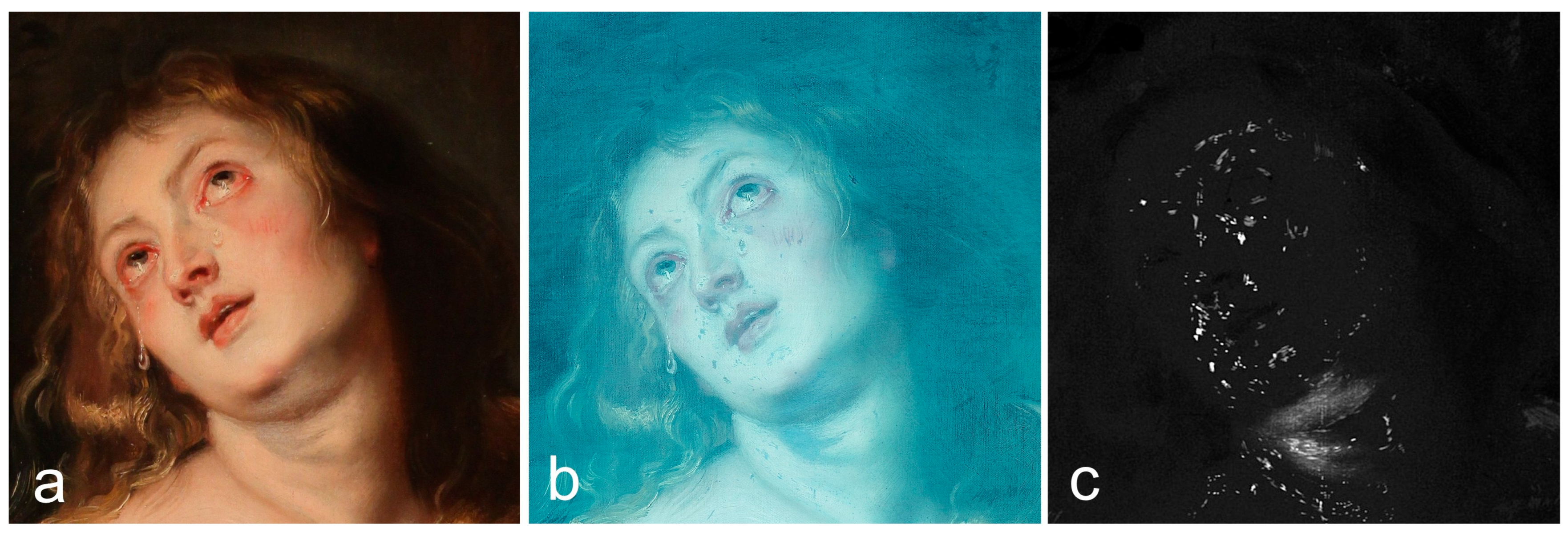
As shown in Figure 6b, blue fluorescence is uniformly distributed across the painting surface, and no detailed variations in the varnish layer can be distinguished. In contrast, the Pb-Mα map (Figure 6c) reveals pronounced variations in the distribution of faint Pb-Mα signals that are not apparent in the corresponding Pb-L image. Guided by these observations, the painting surface was re-examined in detail. This comparison showed that the spatial variations observed in the Pb-Mα map correspond closely to differences in the varnish layer visible on the painting surface. The Pb-Mα signal intensity is therefore considered to be influenced by the varnish layer, and the observed variations are interpreted as reflecting differences in varnish thickness in the present painting. In particular, the Pb-Mα map clearly reveals a square area of varnish cleaning behind the right elbow, around the flank, where the varnish appears markedly thinner than in the surrounding areas. This localized feature cannot be recognized in the UVF image and is only faintly discernible by direct visual inspection, demonstrating the complementary value of MA-XRF in guiding the visual assessment of subtle surface features.
Figure 6.
Comparison of the same region of interest around the right elbow showing localized varnish thinning. (a) Visible-light image. (b) UVF image. (c) Pb-Mα map.
4.1.2. Inscription
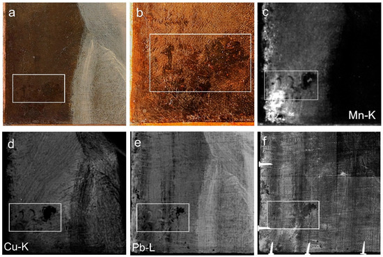
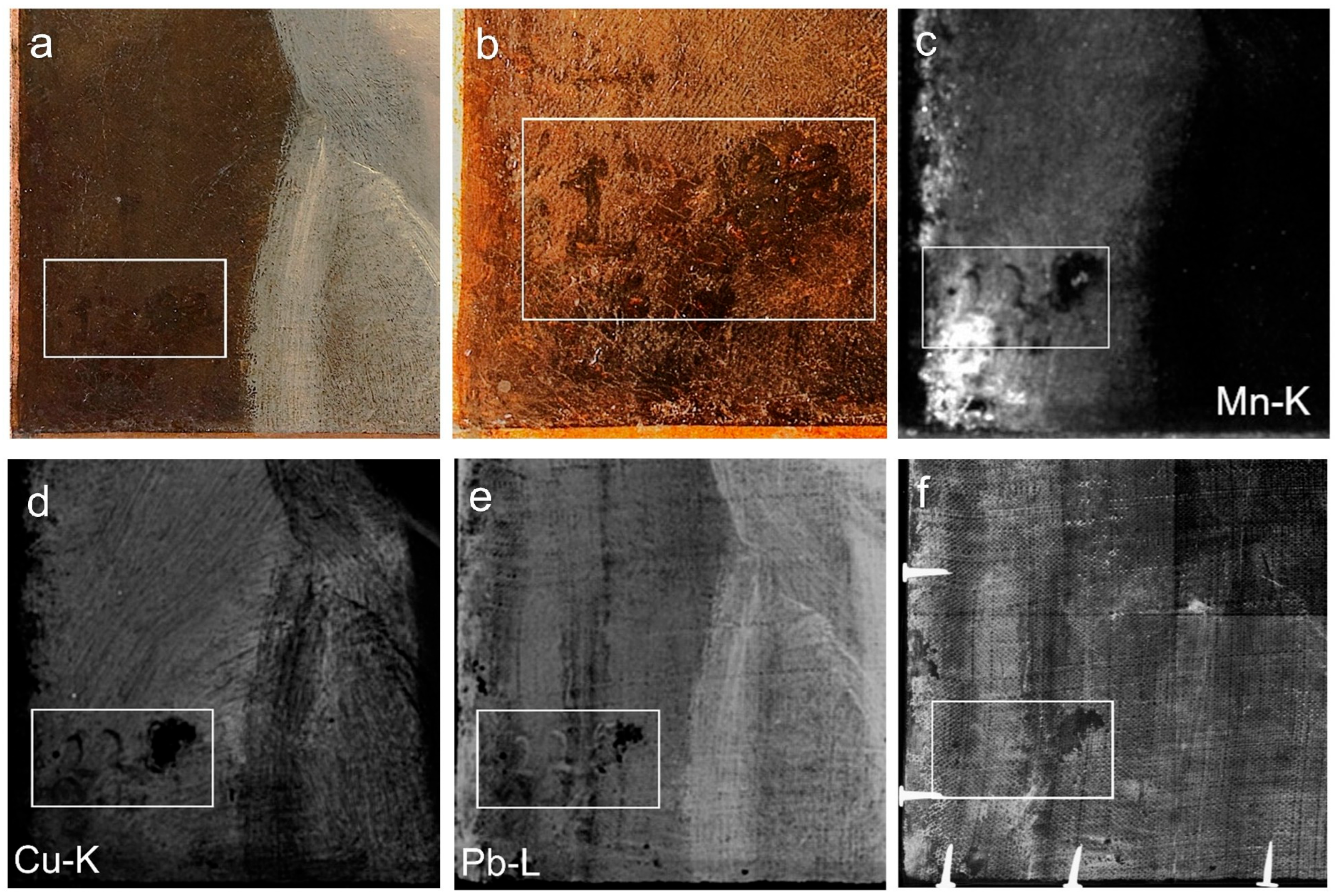
An inscription located in the lower left corner of the painted surface (Figure 7a–f) was examined using multimodal imaging. Under visible light, the numeral “1” is discernible in brown pigment. Pb-Lβ mapping reveals the inscription “22□”, executed in a Pb-containing material over a Cu-containing paint layer. An enlarged Mn-Kα map is shown in Figure 7c. The numeral “1” can be identified to the left of the hundreds digit “2”. As indicated by the Mn-Kα map, this numeral was written using a Mn-containing material. In contrast, the inscription “22□”, identified in the Pb-Lβ map, was written with a Pb-containing material and overlies the Mn-containing inscription. The inscription “22□” appears as a dark feature in the Mn-Kα map because the Pb-containing material is considered to attenuate the underlying Mn-Kα signal. Similarly, in the Cu-Kα map, the inscription appears dark because the Pb-containing material attenuates the Cu-Kα fluorescence signal (Figure 8). X-radiography further shows that the area corresponding to the final, illegible character has suffered paint loss down to the imprimatura or ground layer, making the survival of the original character highly unlikely.
Figure 7.
Inscription in the lower-left corner of the painting documented by visible-light and analytical imaging. The white boxes indicate the corresponding area in each image. (a) Visible-light image. (b) Enlarged view of the visible-light image. (c) Mn-Kα map. (d) Cu-Kαmap. (e) Pb-Lβmap. (f) XRR.
Figure 8.
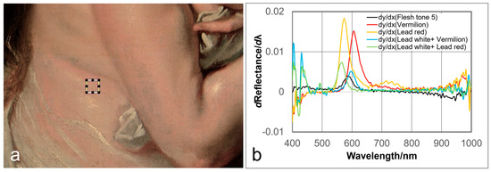
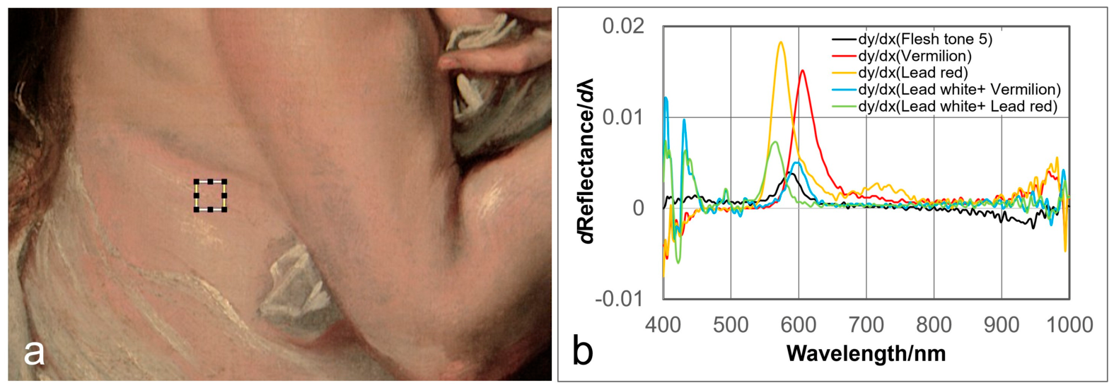
RIS analysis of the flesh tones. (a) Hyperspectral image showing the region of interest (ROI) at location H in Figure 4. The spectra were extracted from the area indicated by the box. (b) First-derivative reflectance spectra of the selected ROI and reference pigment samples.
4.1.3. Flesh Tone and Hair
MA-XRF analysis confirmed high counts of Hg-Lα and S-Kα in shaded areas and regions exhibiting heightened redness in flesh tones, thereby verifying the presence of vermilion (Figure 3). In bright, whitish flesh areas, the distribution of Hg and S is unclear, making it difficult to definitively establish vermilion’s presence. Similarly, MA-XRF mapping cannot confirm the presence of red earth-based pigments. Eight flesh-tone areas were examined by RIS. To investigate the red component of the flesh tones, the average reflectance spectrum extracted from the region of interest (ROI) at location H (Figure 4 and Figure 8a) was compared, using first-derivative analysis, with reference spectra of vermilion mixed with lead white and red lead mixed with lead white (Figure 8b). The first-derivative spectrum of the flesh tone lies intermediate between those of the two reference mixtures, indicating that the red component could be attributed to either vermilion or red lead. Consequently, a definitive distinction between the two pigments cannot be made on the basis of the RIS data alone.
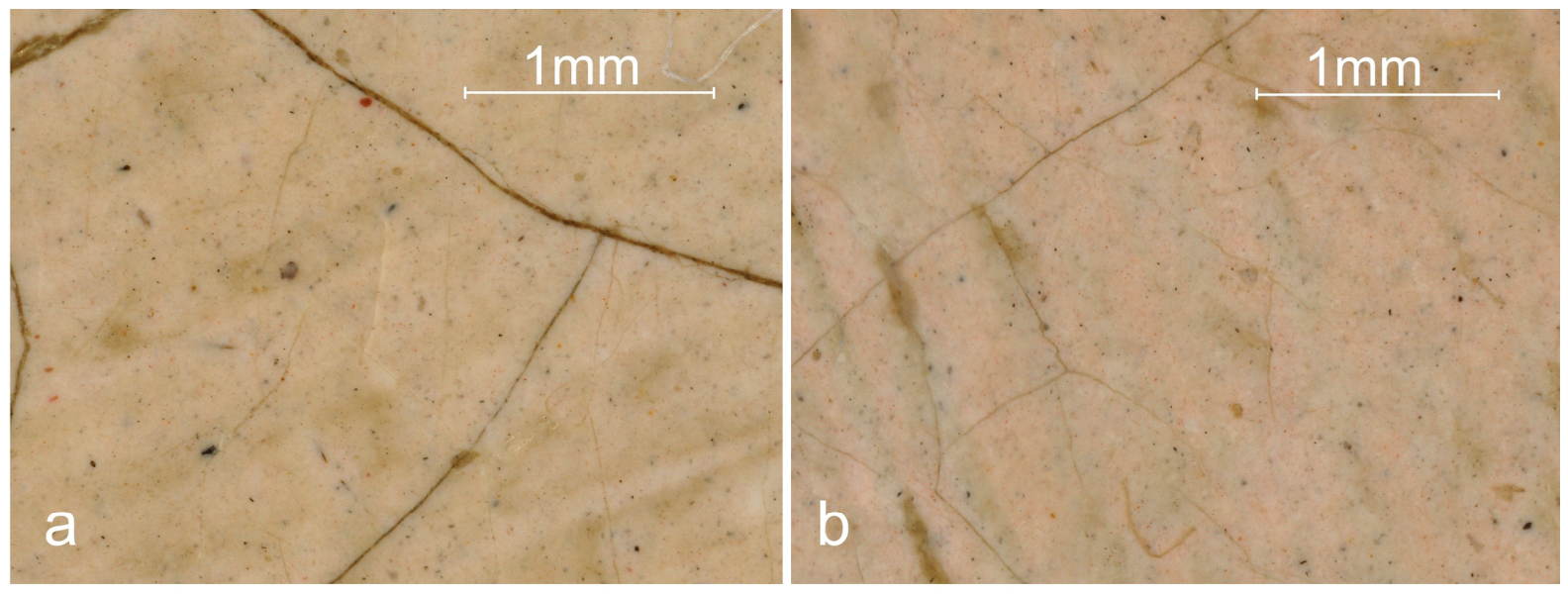
DMI revealed two types fine red particles, reddish-brown transparent lake pigments, and fine black particles (Figure 9). Taken together, these findings suggest that the flesh tones were primarily modelled with vermilion, in combination with red earth pigments (possibly including red ochre), a reddish-brown lake pigment based on Ca-, S-, and K-containing substrates, and a black pigment, possibly ivory black.
Figure 9.
Digital microscopy images acquired from the locations indicated in Figure 4. (a) Location D (forehead), ×90 magnification. (b) Location H (beneath the right arm), ×90 magnification.
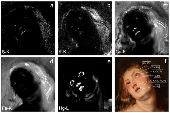
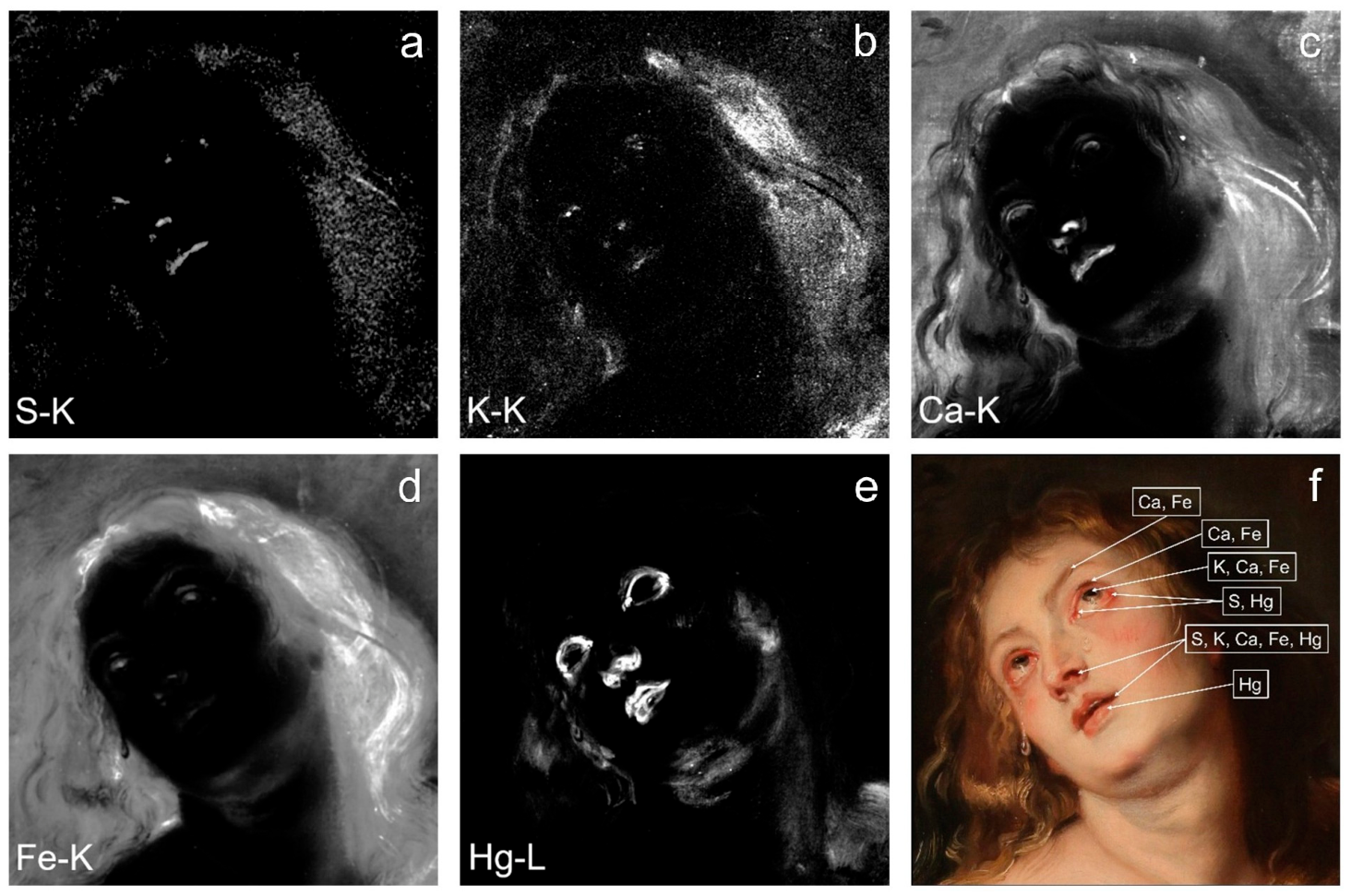
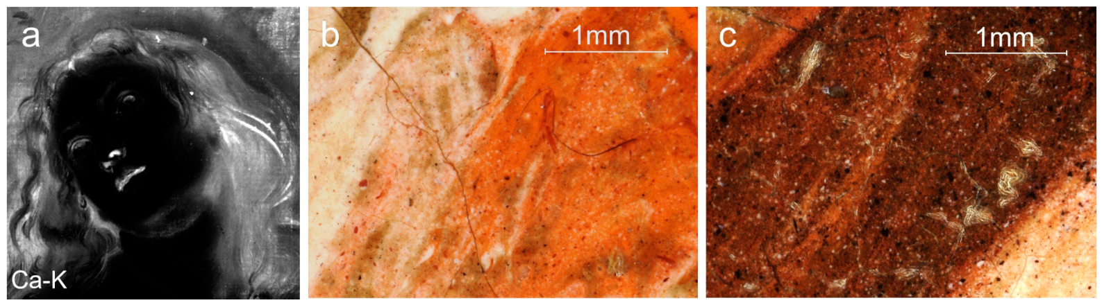
Observations of pigment distribution in the facial area by MA-XRF reveal distinct elemental patterns corresponding to different facial features. The Hg-Lα map shows mercury concentrated around the eyes, nostrils, wings of the nose, and lips (Figure 10e), suggesting the use of vermilion mixed with lead white in modeling these areas. The presence of sulfur at corresponding locations in the S-Kα map further supports the identification of vermilion (Figure 10a). Relatively pure vermilion, apparently unmixed with other pigments, appears to have been applied to the inner and outer corners of the eyes. The K-Kα and Ca-Kα maps show potassium and calcium distributed around the slightly parted mouth, nostrils, and eyelids (Figure 10b,c). In addition, the Fe-Kα map reveals iron in these shadowed regions (Figure 10d), suggesting that the darker passages were likely rendered using a mixture of a reddish-brown lake pigment, earth pigments, and black pigments. Calcium and iron are also distributed in the eyebrows and eyelashes. The pupils appear to have been rendered using black and earth pigments, whereas the flesh tones were likely produced by mixing vermilion with lead white. The distribution of mercury further suggests that the intensity of the reddish flesh tones increases with the relative abundance of vermilion. To facilitate interpretation, the elemental distributions identified by MA-XRF analysis are superimposed on the visible-light image and presented in Figure 10f.
Figure 10.
Element distribution maps of the facial and hair area. All panels show the same region of interest. (a) S-Kα map; (b) K-Kα map; (c) Ca-Kα map; (d) Fe-Kα map; (e) Hg-Lα map; and (f) visible-light image with arrows indicating the principal elemental distributions discussed in the text. Owing to the approximate bilateral symmetry of the face, annotations are shown on one side only for clarity.
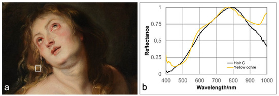
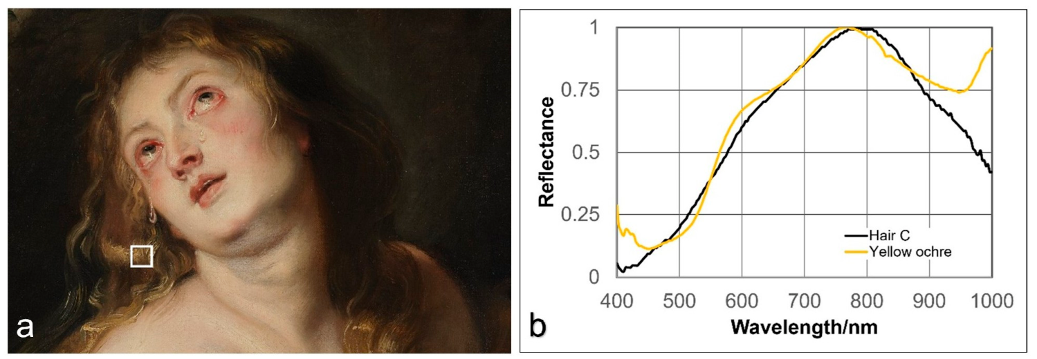
The Fe-Kα and Mn-Kα elemental distribution maps of the hair indicate the presence of iron- and manganese-rich earth pigments, consistent with ochre and brown umber (Figure 3). The Si-Kα, K-Kα, and Ti-Kα maps show that the distributions of Si, K, and Ti closely correspond to those of Fe and Mn, suggesting the use of an ochre pigment containing a significant proportion of clay minerals [20,21]. The visible-region reflectance spectrum obtained from the hair by RIS shows a close correspondence with that of a reference yellow ochre sample (Figure 11b), further supporting the presence of an ochre-based pigment. In the hair extending from the crown to the left temporal region, the distributions of S, K, and Ca may indicate the presence of a yellow lake pigment precipitated on an alum-based substrate, possibly used in combination with chalk (Figure 10a–c).
Figure 11.
RIS analysis of Magdalene’s hair. (a) Region of interest (ROI) at location C in Figure 4. The white box indicates the area used for spectral extraction. (b) Normalized visible reflectance spectra of the selected ROI and a reference sample of yellow ochre.
MA-XRF elemental mapping also reveals a large curl in the shadowed portion of the hair draped over the left shoulder, extending toward the knee as though supported by the left arm. Although this feature is difficult to discern in visible-light images, it is clearly resolved in the elemental distribution maps. While the Ti detected in the ochre-colored areas is likely to be of natural origin, the distinct Ti distribution observed in the upper left portion of the painting is most likely attributable to modern titanium white present in restoration retouchings.
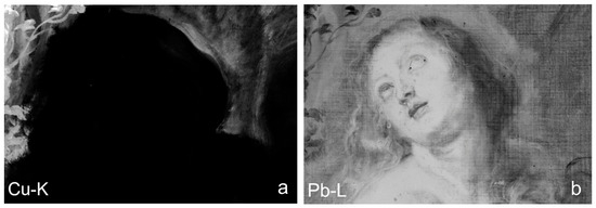
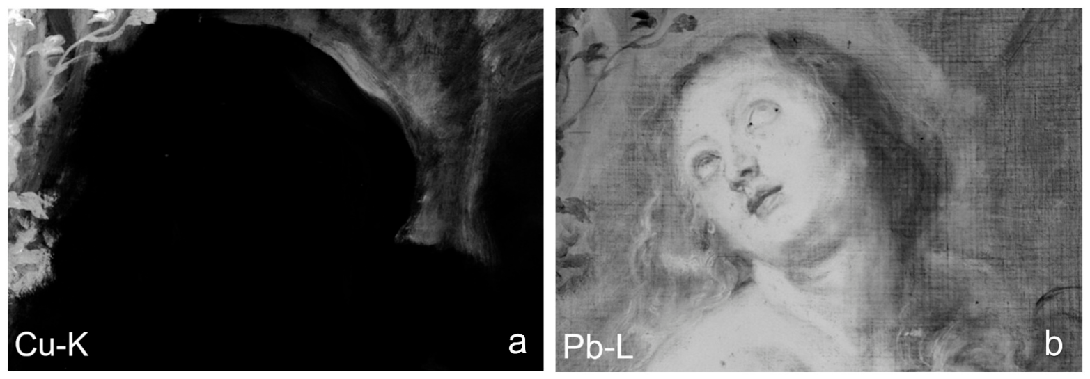
Particular attention to the Cu-Kα and Pb-Lβ maps (Figure 12a,b) reveals relatively high concentrations of both elements on the left side of the head. A comparable elemental distribution has been described by Geert Van der Snickt and Kirsten Derks [14,22] as a dark halo. Nevertheless, in the absence of sufficient comparative evidence, the present study refrains from further discussion of this feature.
Figure 12.
Elemental distribution maps showing the localized enrichment of Cu and Pb on the left side of the head. (a) Cu-Kα map. (b) Pb-Lβ map.
4.1.4. Blue Sky and Cloud
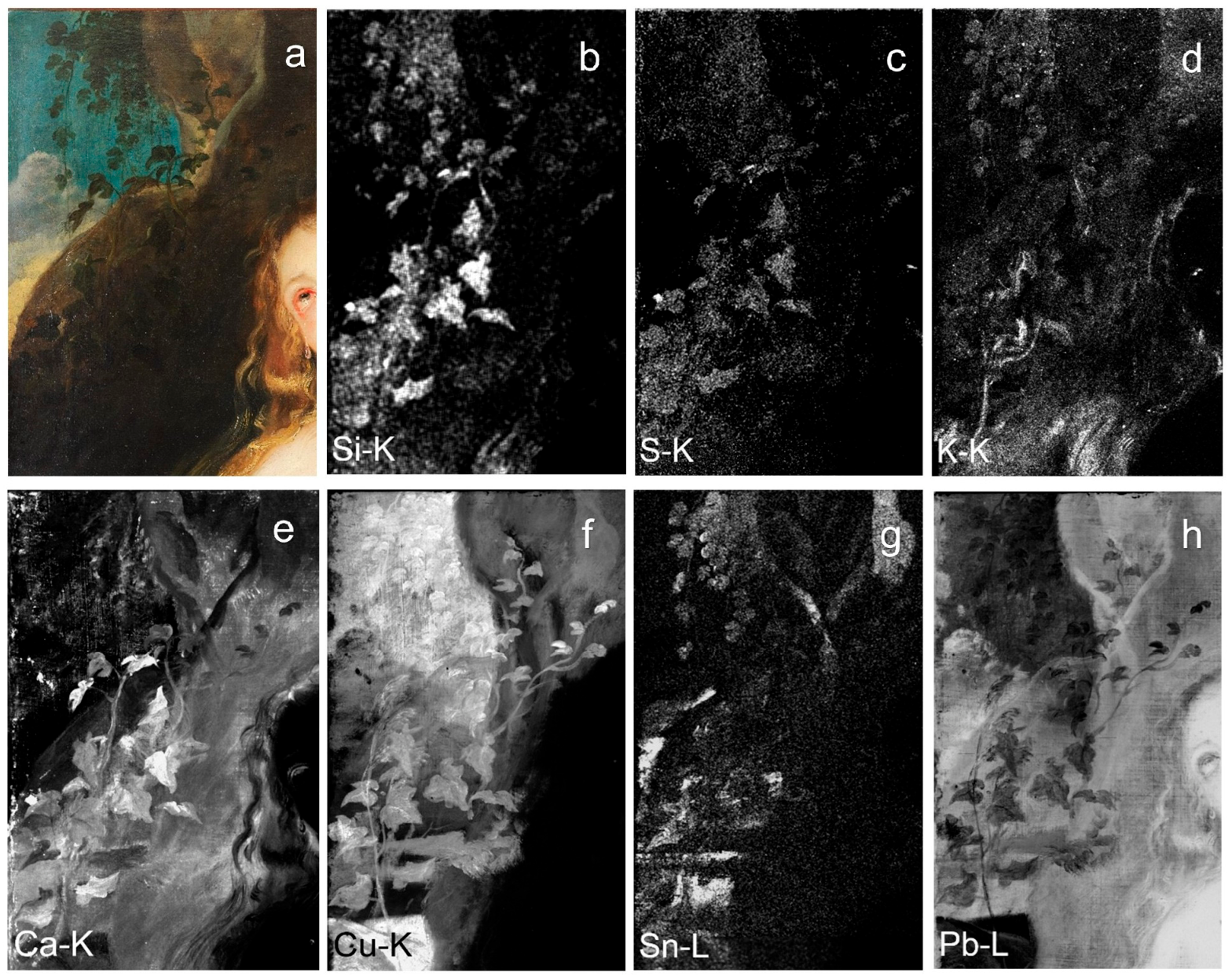
MA-XRF analysis reveals the distributions of S and Cu in the blue sky (Figure 13c,f). The elemental distributions are consistent with the presence of azurite and a copper-containing blue pigment, although the Cu signal alone cannot distinguish between azurite, a copper-containing pigment, or lapis lazuli. The Si signal is weak and insufficient to support the presence of lapis lazuli (Figure 13b). The visible patches of Ca, originating from the ground layer, reflect the thin application of the blue paint layer (Figure 13e). The Pb distribution indicates the use of lead white in the clouds (Figure 13h), whereas the Sn distribution along the ridgelines suggests the presence of lead-tin yellow (Figure 13g). The faint Cu distribution detected within the clouds further suggests that the clouds may have been painted over an underlying blue sky layer.
Figure 13.
Visible-light image and selected MA-XRF elemental distribution maps of the sky, clouds and plants in the upper-left portion of the composition: (a) visible-light image; (b) Si-Kα; (c) S-Kα; (d) K-Kα; (e) Ca-Kα; (f) Cu-Kα; (g) Sn-Lα; and (h) Pb-Lβ.
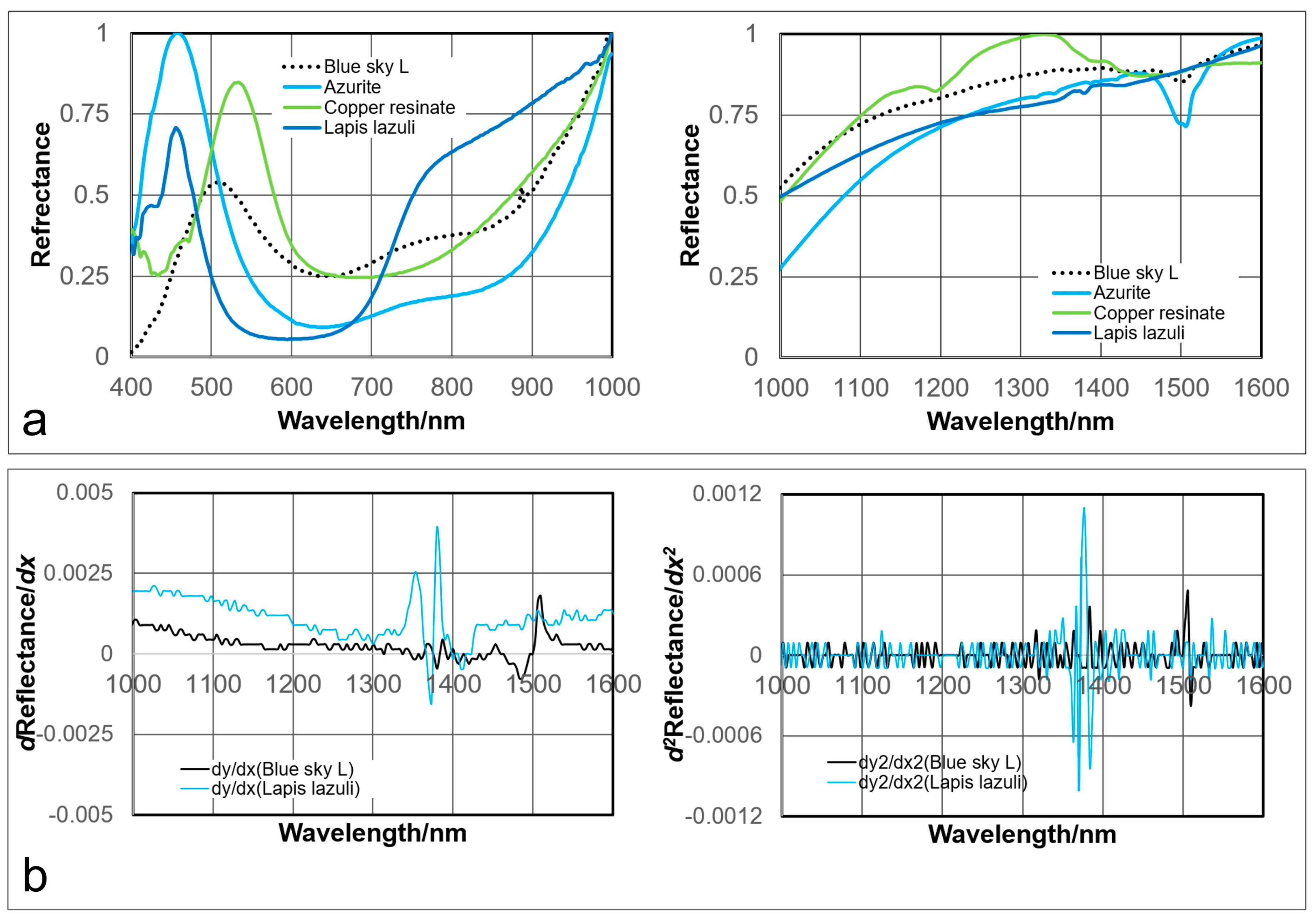
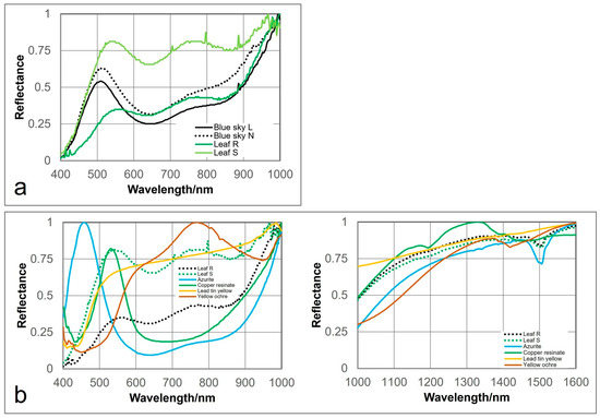
RIS analysis of eight areas of the blue sky revealed spectral features in the visible region that are consistent with azurite and copper resinate. An absorption feature centered around 1500 nm in the near-infrared region further suggests that azurite is likely to be the principal blue pigment (Figure 14a). Application of first- and second-derivative processing to the near-infrared spectra revealed a weak feature near 1380 nm that is consistent with lapis lazuli (Figure 14b). Because this feature is extremely weak, however, it cannot be regarded as definitive evidence for the presence of lapis lazuli. No spectral features characteristic of smalt or malachite were detected by RIS analysis.
Figure 14.
Comparison of reflectance spectra obtained from location L in Figure 4 (the blue sky) and reference pigments. (a) Normalized visible and near-infrared reflectance spectra of the blue sky, azurite, copper resinate, and lapis lazuli. (b) First-derivative spectra and second-derivative spectra of the blue sky and lapis lazuli.
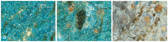
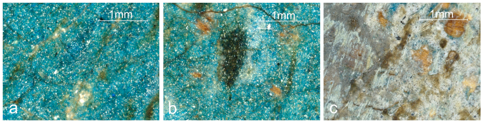
DMI observations show that the deep blue sky appears to comprise uniformly sized blue pigment particles together with slightly smaller, uniformly sized white pigment particles and finely dispersed, slightly flake-like black pigment particles. Particularly dense accumulations of the blue pigment particles are observed in some areas (Figure 15a,b). The clouds appear to comprise white pigment particles together with finely dispersed, flake-like black pigment particles, the latter being densely distributed throughout the cloud passages (Figure 15c).
Figure 15.
Digital microscopy images acquired from the locations indicated in Figure 4. (a) Location L (blue sky), ×90 magnification. (b) Location N (blue sky), ×90 magnification. (c) Location O (cloud), ×90 magnification.
Taken together, these observations suggest that the blue sky was most likely rendered using azurite together with lead white, the clouds with lead white and ivory black, and the golden sky along the ridgeline with lead-tin yellow in combination with lead white. The presence of lapis lazuli as an additional blue pigment cannot be excluded, although the available evidence is insufficient to confirm its use. No definitive evidence for a yellow lake pigment was obtained; however, if present, its substrate would be expected to contain sulfur but little or no potassium.
4.1.5. Plants
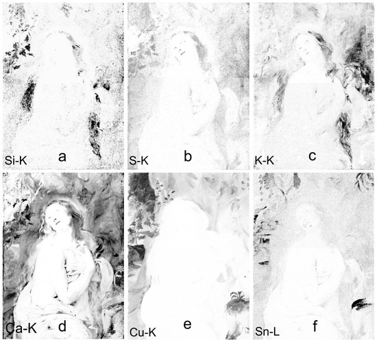
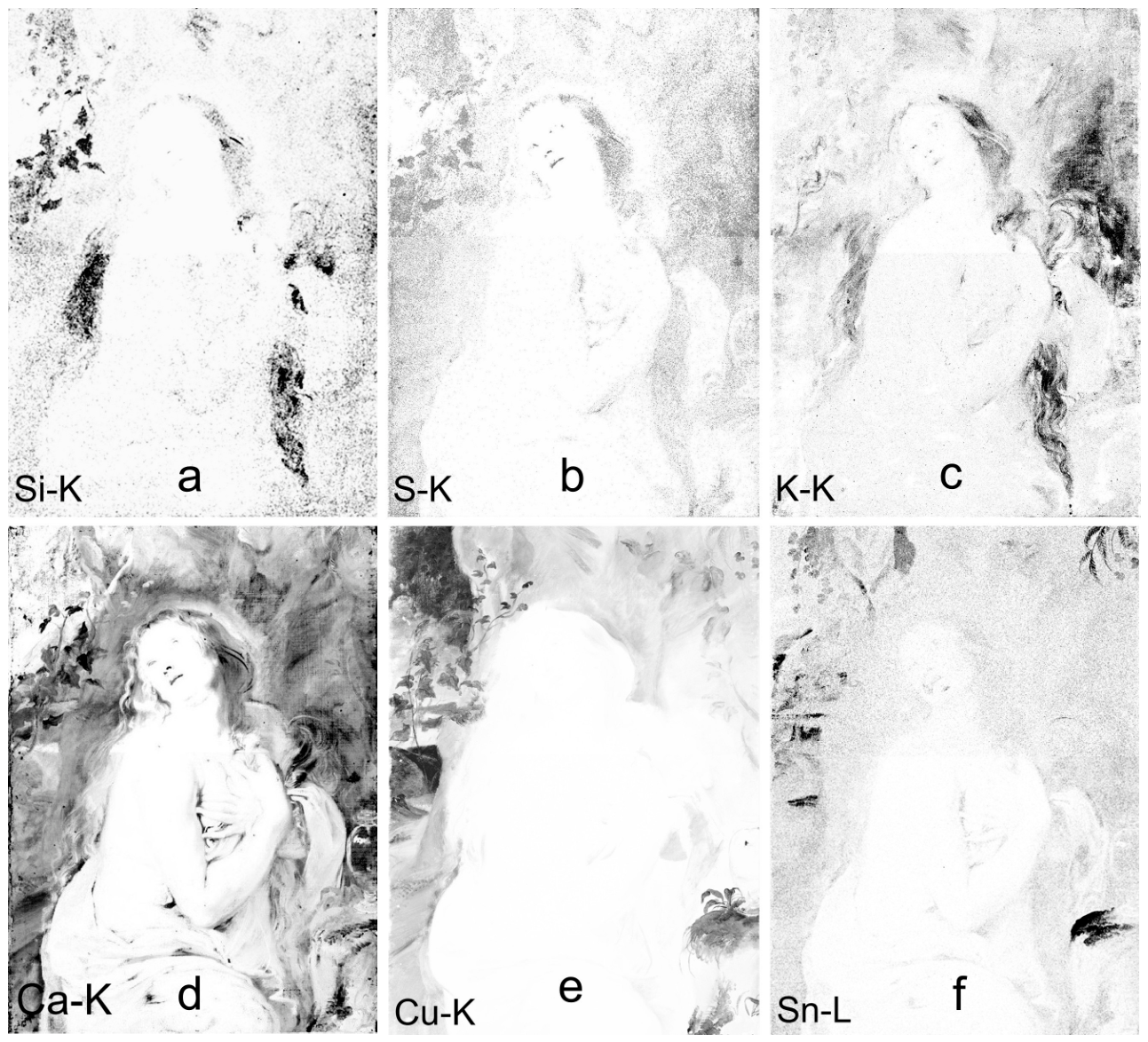
To facilitate visualization of the vegetation, the MA-XRF elemental maps are presented as inverted grayscale images, in which darker areas correspond to higher concentrations of the respective elements (Figure 16). Among the plants depicted in the background behind the Magdalene in the upper left of the composition, MA-XRF analysis reveals that the trailing vine-like plant descending from above is associated with the distributions of Si, S, K, Cu, Sn, and Pb (Figure 16a–c,e,f), whereas the ivy growing upward from below is associated with the distributions of Si, S, Ca, and Cu (Figure 16a,b,d,e). The Sn distribution is characteristic of the descending vine-like plant, whereas the Ca distribution is distinctive of the upward-growing ivy.
Figure 16.
Inverted grayscale representations of selected MA-XRF elemental maps, presented to improve the visualization of the distribution patterns of the vegetation. In this figure, the greyscale is inverted relative to the other MA-XRF maps; darker regions represent higher elemental intensity. (a) Si-Kα; (b) S-Kα; (c) K-Kα; (d) Ca-Kα; (e) Cu-Kα; and (f) Sn-Lα.
Enlarged visible-light views and corresponding DMI are shown in Figure 17. DMI observations revealed no identifiable blue pigment particles in either the vine-like plant or the ivy. Instead, the vine-like plant appears to consist predominantly of a transparent, resinous green paint, whereas the ivy is characterized by a semi-transparent, resinous brown paint. RIS analysis of sixteen areas across the vine-like plant and the ivy revealed that the reflectance peak was clearly shifted towards longer wavelengths relative to that of the blue sky, suggesting that the dominant spectral contributors in the vegetation differ from those of the sky (Figure 18a). Comparison of the RIS spectra obtained from the vine-like plant and the ivy with those of reference pigments indicates that the dominant spectral features are consistent with azurite and copper resinate. In particular, the absorption feature near 1500 nm shows good agreement with that of azurite, although the presence of pigment mixtures cannot be excluded (Figure 18b). However, owing to the transparency of these paint layers, the underlying blue paint of the sky remains clearly visible through the vine-like and ivy-like plants (Figure 17). Consequently, the apparent azurite-like spectral signature observed in the vegetation is likely to be enhanced by the contribution of the underlying blue sky layer, resulting in a stronger azurite-like response in the RIS spectra.
Figure 17.
Enlarged visible-light views and corresponding digital microscopy images acquired from the locations indicated in Figure 4. (a) Enlarged visible-light image of location R (vine-like plant). (b) Digital microscopy image of location R (vine-like plant), ×90 magnification. (c) Enlarged visible-light image of location S (ivy-like plant). (d) Digital microscopy image of location S (ivy-like plant), ×90 magnification.
Figure 18.
Comparison of RIS reflectance spectra obtained from representative vegetation areas (locations shown in Figure 4) and reference pigments. (a) Normalized visible reflectance spectra from locations L and N (blue sky) and R and S (plant leaves). (b) Normalized visible and near-infrared reflectance spectra from locations R and S (plant leaves), compared with reference spectra of azurite, copper resinate, lead-tin yellow, and yellow ochre.
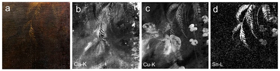
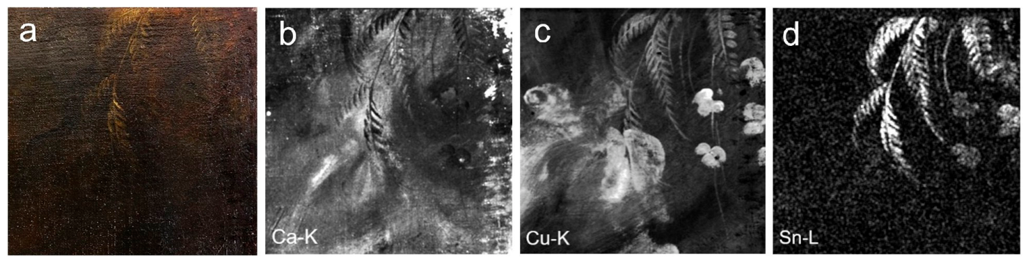
Cu and Sn are detected in the ferns growing on the rock wall in the upper right corner (Figure 19a–d), while Cu is detected in the vegetation growing on the rock face to the right of Magdalene’s head (Figure 16e). The fact that sulfur and potassium are present only in trace amounts in these areas suggests that, if a yellow lake pigment was used, it was present only in very small quantities (Figure 16b,c). In addition, the co-distribution of Cu and Sn in the ferns is consistent with the presence of lead-tin yellow, which may have contributed to their more pronounced yellowish tonality compared with the surrounding foliage.
Figure 19.
MA-XRF elemental maps of the fern-like vegetation in the upper-right corner of the painting. (a) Visible-light image; (b) Ca-Kα map; (c) Cu-Kα map; (d) Sn-Lα map.
Taken together, these results suggest that the vine-like plant was most likely painted using copper resinate together with lead-tin yellow and a yellow lake pigment precipitated on an alum-based substrate containing S and K. By contrast, the ivy appears to have been painted with copper resinate, chalk, and a yellow lake pigment that may have been prepared on an alum-based substrate (S). The ferns are likewise consistent with the use of copper resinate and lead-tin yellow, whereas the vegetation below appears to have been executed using copper resinate and chalk. In both cases, particles consistent with ivory black and orange-yellow earth pigments are also observed. However, given the characteristic distribution of calcium, the possibility that the material provisionally interpreted here as copper resinate may instead represent blue verditer cannot be excluded, and a definitive identification is therefore not yet possible [23].
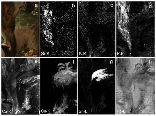
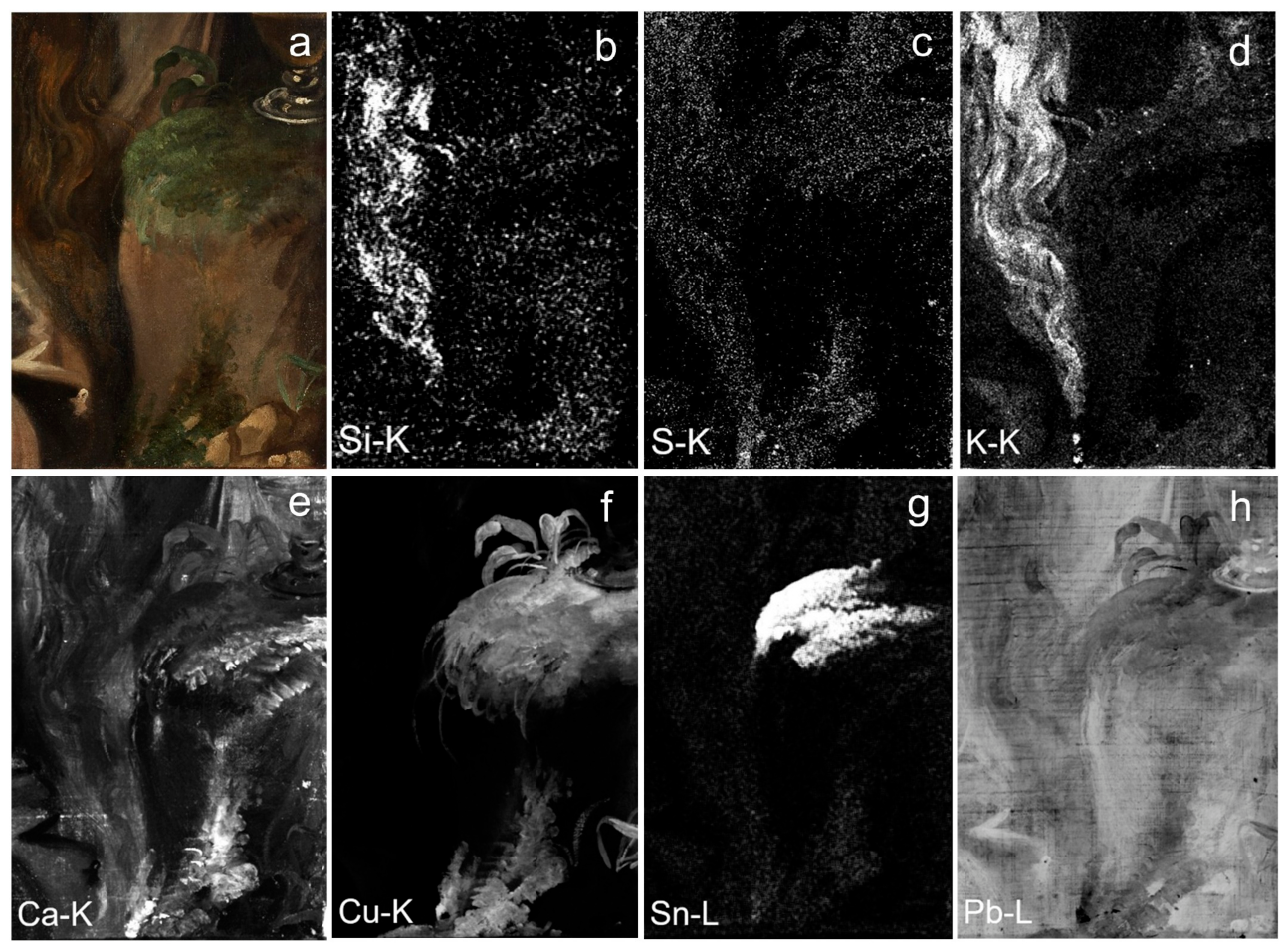
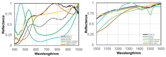
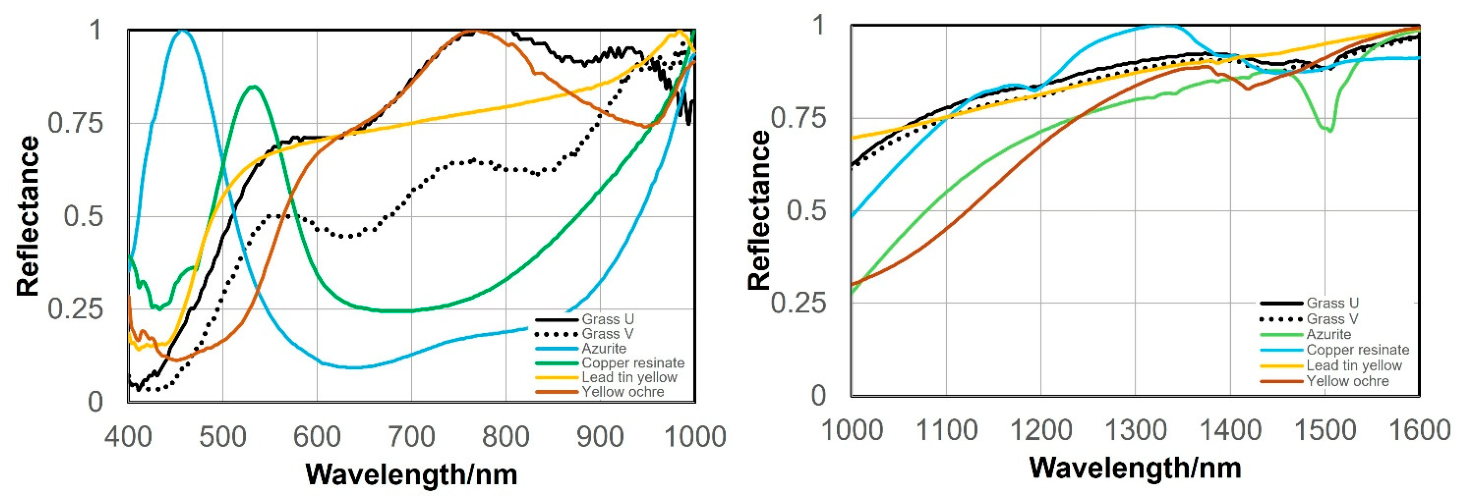
MA-XRF analysis of the vegetation growing on the rock supporting the ointment jar shows that the upper foliage is associated with the distributions of S, Ca, Cu, and Sn, whereas the lower foliage is associated with the distributions of S, Ca, and Cu (Figure 20). RIS analysis further reveals visible- and near-infrared spectral features consistent with copper resinate, yellow ochre, and lead-tin yellow (Figure 21). Digital microscopy (DMI) shows that the upper foliage, where Cu and Sn are concentrated, appears to comprise a green resinous paint together with blue pigment particles, yellow particles, white pigment particles, and black pigment particles (see location U in Figure 4). In contrast, the lower foliage appears to comprise a transparent resinous paint together with blue pigment particles, a semi-translucent white pigment, and a yellow lake pigment (see location W in Figure 4).
Figure 20.
MA-XRF elemental distribution maps showing the vegetation growing on the rock beneath the ointment jar in the lower-right corner of the painting. (a) Visible-light image; (b) Si-Kα map; (c) S-Kα map; (d) K-Kα map; (e) Ca-Kα map; (f) Cu-Kα map; (g) Sn-Lα map; (h) Pb-Lβ map.
Figure 21.
Comparison of normalized visible and near-infrared RIS reflectance spectra obtained from locations U and V (vegetation growing on the rock beneath the ointment jar; locations shown in Figure 4) with reference spectra of azurite, copper resinate, lead-tin yellow, and yellow ochre.
Taken together, these analytical results suggest that the upper foliage was most likely painted using a copper-containing green pigment, together with lead-tin yellow, chalk, and a yellow lake pigment. Likewise, the lower foliage appears to have been executed using the same copper-containing green pigment, chalk, and a yellow lake pigment, but without the addition of lead-tin yellow [17].
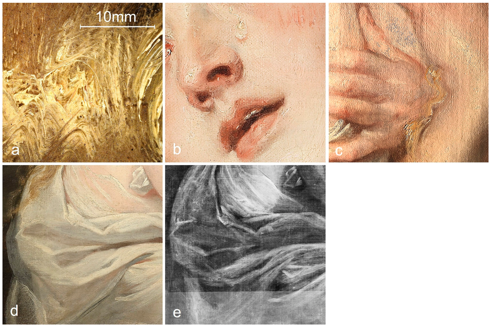
4.1.6. Painting Technique & Brush Work
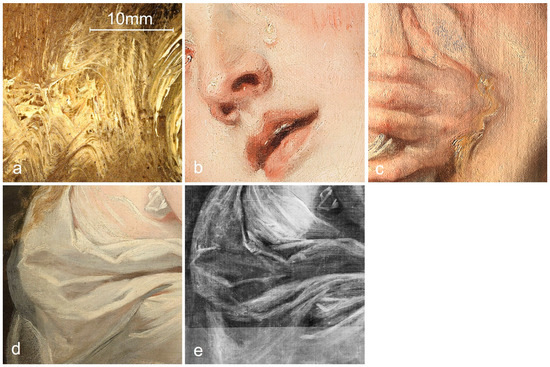
The depiction of the face, hair, hands, and white robe exemplifies the masterful brushwork associated with the “furia del pennello”—characterized by light, rapid handling (Figure 22b,d,e) [24]. This is evident in the confident modeling of the figure achieved through rapid brushstrokes, employing techniques such as wet-in-wet painting (Figure 22a,c), impasto (thickening paint to emphasize highlights) (Figure 22b), and feathering (subtly blending adjacent hues) (Figure 22c). Although the brushstrokes have been partially flattened due to the heat applied during past lining procedures, these characteristic painterly qualities remain clearly discernible.
Figure 22.
Representative examples of painting techniques and brushwork. (a) Wet-in-wet handling in the hair (location C in Figure 4, ×10). (b) Facial detail showing furia del pennello and impasto modeling. (c) Wet-in-wet handling and feathering in the hand area. (d) Visible-light image of the white drapery corresponding to the XRR shown in (e). (e) XRR detail of the white drapery revealing brushwork characteristic of furia del pennello.
4.1.7. Overpainting and Repainting
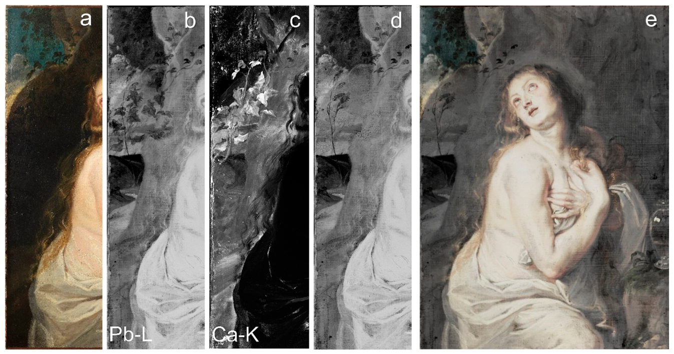
MA-XRF Fe-Kα and Mn-Kα mapping confirms that earth pigments were applied behind the Magdalene, leaving only the upper blue sky and part of the clouds untouched. X-radiography together with Pb-Lβ, Cu-Kα, and Sn-Lα mapping further reveals concealed features that are invisible under visible light (Figure 3, corresponding ROI in Figure 23a–d). These findings indicate the presence of a pastoral landscape extending beyond the rock face in the distance. The ivy-like leaves, which are clearly distinguished in the Ca-Kα map (Figure 23c), were used as a reference for digitally masking the corresponding foliage in the Pb-Lβ image (Figure 23b). This processing revealed a slender tree rising from the foot of a hill and bending in the wind (Figure 23d). From the base of the hill, features resembling cultivated fields or a winding river extend towards the foreground. Near the horizon, clouds tinged with golden hues rise above the landscape, while the slender tree appears to sway in the wind across the open countryside (Figure 23e).
Figure 23.
Evidence of overpainting and compositional changes. (a) Visible light image. (b) Pb-Lβ map. (c) Ca-Kα map. (d) Processed Pb-Lβ image. (e) Overlay of the processed Pb-Lβ image and the visible-light image.
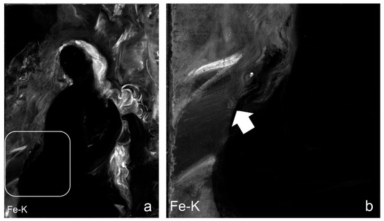
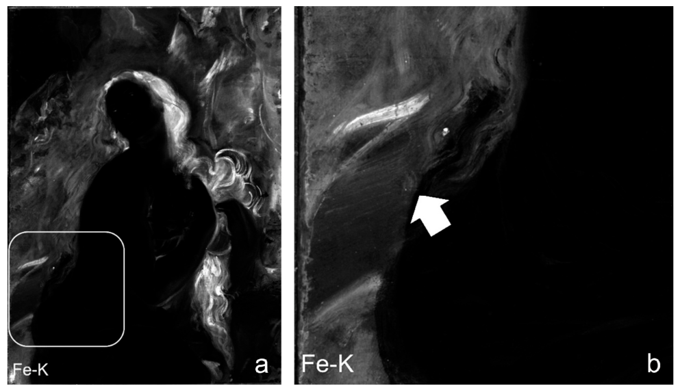
The Fe-Kα and Mn-Kα maps reveal a subtle feature near the waist of Mary Magdalene that, from an iconographic perspective, may visually resemble an open book viewed from below (Figure 24a,b). This observation remains highly tentative because the feature is only faintly discernible, its original position within the composition cannot be determined, and the available analytical data are insufficient to support a secure identification.
Figure 24.
Evidence of overpainting and compositional changes. (a) Fe-Kα map showing the boxed region containing a subtle feature near Magdalene’s waist that may, from an iconographic perspective, be interpreted as resembling an open book. (b) Enlarged view of the boxed region in (a), showing a feature resembling an open book viewed obliquely from below; the arrow indicates the upward direction of the viewing perspective.
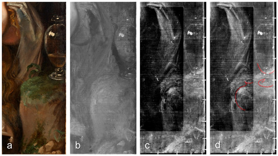
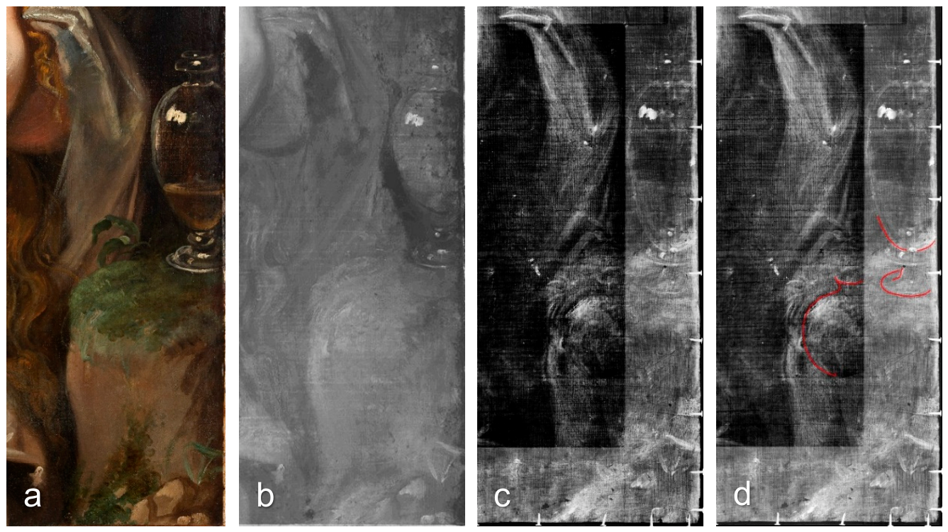
In the IRR image of the ointment jar region, only faint traces corresponding to the lower part of an earlier ointment jar can be discerned beneath the lower edge of the present jar (Figure 25b). In contrast, the X-radiograph shows features that are tentatively interpreted as evidence of two earlier configurations of the ointment jar beneath the visible vessel (Figure 25c). One feature is located slightly below the present ointment jar and largely overlaps it, exhibiting a similar overall shape. Another feature, positioned toward the lower left, appears more rounded and differs in form from the visible jar. The interpretative red-line overlay illustrates the tentative reconstruction of these inferred underlying configurations to facilitate recognition of the concealed features (Figure 25d).
Figure 25.
Evidence of overpainting and compositional changes. (a) Visible-light image of the ointment jar region. (b) IRR. (c) XRR. (d) XRR shown in (c) with an interpretative red-line overlay illustrating the tentative reconstruction of the inferred earlier configuration of the ointment jar.
Unlike X-radiography, which records density variations throughout the paint stratigraphy, IRR and MA-XRF provide different types of information. The visibility of concealed features in IRR depends on the infrared optical properties of the overlying pigments. Consequently, only limited traces of the underlying ointment jar are discernible in the IRR image. Likewise, the MA-XRF elemental maps do not provide sufficient contrast to delineate the complete underlying forms, because they record the distribution of individual elements rather than buried morphological features. As a result, the concealed revisions of the ointment jar are most clearly resolved in the X-radiograph, whereas only partial evidence is observed in the IRR and MA-XRF datasets.
It is particularly noteworthy that, despite the numerous revisions identified elsewhere in the painting, the overall form of Mary Magdalene’s figure remained essentially unchanged and, apart from the numerous small retouchings applied during later conservation treatments, has been preserved largely in its original state.
4.1.8. Later Conservation Retouching
As the UVF and the Zn-Kα image reveal, numerous areas across the entire figure of Magdalene show meticulous conservation retouching to address small losses and stains (Figure 3 and Figure 26). Significant retouching is evident near the left and right edges of the painting, with some areas filled and retouched over what appears to be the original underlying layer. Where raised sections of the canvas have been abraded, underlying paint layers are exposed, suggesting that partial paint loss may have occurred during cleaning. Such areas are widespread across the painting, which may indicate that a degree of cleaning was undertaken.
Figure 26.
Comparison of the face region of interest (ROI) in (a) visible light, (b) ultraviolet-induced visible fluorescence (UVF), and (c) the Zn-Kα map.
4.2. Pigments
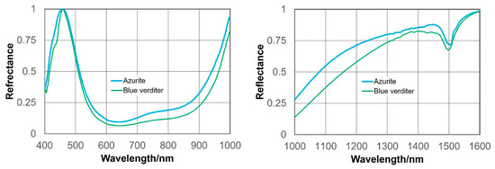
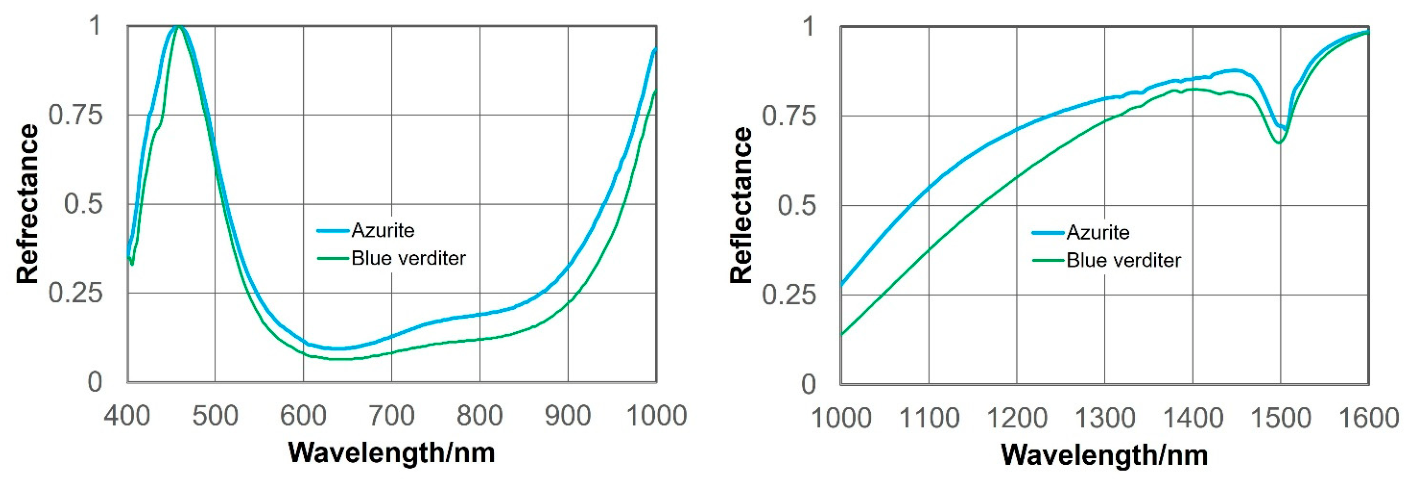
The pigment assemblage identified in the Tokyo painting is summarized in Table 3 The possible presence of lapis lazuli is suggested but cannot be confirmed from the spectral characteristics shown in Figure 14b. Likewise, blue verditer cannot be distinguished reliably from azurite on the basis of the present MA-XRF and RIS data alone (Figure 27).
Table 3.
Proposed pigment identifications for the Tokyo painting.
Figure 27.
Comparison of normalized RIS reflectance spectra of the reference pigments azurite and blue verditer.
The pigment identifications presented in this study are based primarily on the combined interpretation of elemental distributions obtained by MA-XRF and spectral information acquired by RIS. Although these complementary datasets provide strong evidence for pigment interpretation, they do not always permit definitive identification of individual pigments, particularly where chemically or spectrally similar materials exhibit overlapping analytical characteristics. Consequently, the pigment identifications proposed in this study should be regarded as the most probable interpretations based on the available non-invasive analytical evidence. Future investigations employing complementary molecular techniques, such as Raman spectroscopy, would further strengthen and refine these pigment identifications.
Because lapis lazuli was an exceptionally expensive pigment, its use was generally restricted to artists working on prestigious commissions or those with established patronage. Previous research indicates no instances of lapis lazuli use in Van Dyck’s early works [25,26,27,28]; examples appear around the time of his “Charity”, painted in 1627–1628. Regarding the date of the Tokyo work, Müller Hofstede suggests 1618–1620 [11], while Nakamura initially proposed the years 1617–1618 [2], later revising this to 1618–1620 [3]. Both periods fall within Van Dyck’s first Antwerp phase, during which he likely may not yet have had access to employ lapis lazuli.
The identified ground composition, pigment palette, and overall stratigraphic structure are consistent with established seventeenth-century Flemish painting practice and with materials documented in paintings associated with both Rubens and Van Dyck [29]. On the basis of materials and technique alone, however, no conclusive evidence permits a definitive attribution to either artist. Rather, the technical evidence demonstrates that the painting was executed within a material and technical tradition shared by both Rubens and Van Dyck.
4.3. Comparison with Titian’s Paintings and Cornelis Cort’s Engraving
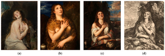
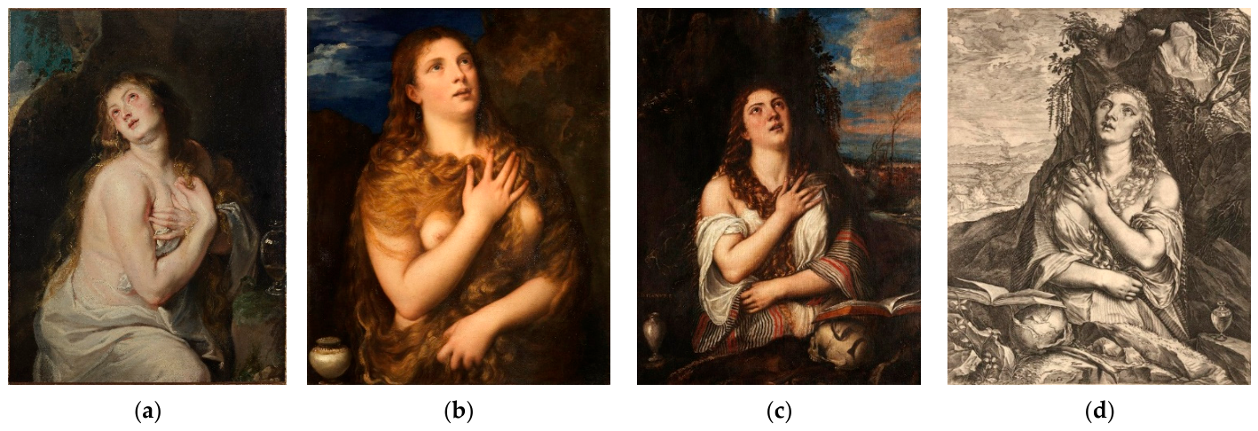
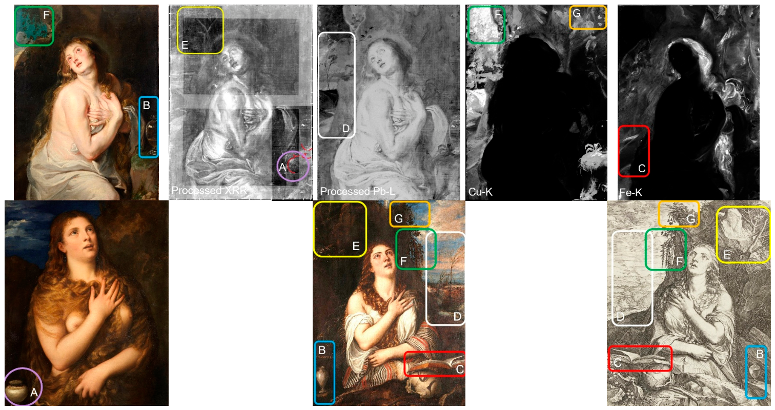
The painting that served as the model for Cornelis Cort’s engraving Penitent Magdalene is generally considered to have been one of several versions of the composition (Figure 28), including those now in the Museo e Real Bosco di Capodimonte, the Staatsgalerie Stuttgart, the Hermitage Museum, or the Royal Site of San Lorenzo de El Escorial. However, it remains unclear which version served as the model for Cort’s engraving, and no previous study appears to have addressed this question explicitly. In the present study, the Naples version is adopted as the most likely candidate [30]. This interpretation is based on the close correspondence between the Tokyo painting and the Naples version in several compositional details, including the strip of sky visible above the rock face, the vine-like plant descending from the top of the rock face, the clouds extending across the sky, and the wind-blown smoke, whose silhouette resembles that of trees. Comparison of the Tokyo painting with the Naples version and Cort’s engraving further reveals a number of close similarities in the depiction of the human figure (Figure 29).
Figure 28.
Comparison of the Tokyo painting with Titian’s Penitent Magdalene and the engraving by Cornelis Cort after Titian. From left to right (a–d): the Tokyo painting (visible-light image); Titian, Penitent Magdalene, 1531–1535, oil on canvas, Galleria Palatina, Palazzo Pitti, Florence; Titian, Penitent Magdalene, c. 1550, oil on canvas, Museo e Real Bosco di Capodimonte, Naples; and Cornelis Cort after Titian, The Penitent Magdalene, 1566, engraving, Rijksmuseum, Amsterdam. Image credits: (b) Tiziano Vecellio, Santa Maria Maddalena, Galleria Palatina, Inv. Pal. (1912) n. 67. Courtesy of Gallerie degli Uffizi; (c) Titian, Penitent Magdalene, Museo e Real Bosco di Capodimonte. Courtesy of Museo e Real Bosco di Capodimonte; (d) Courtesy of the Rijksmuseum (Public Domain).
Figure 29.
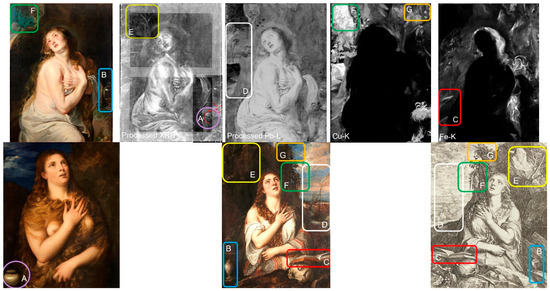
Comparative analysis of the Tokyo painting, Titian’s Penitent Magdalene and Cornelis Cort’s engraving after Titian. Corresponding compositional features are indicated by matching letters and outlined frames. Top row, from left to right: visible-light image of the Tokyo painting showing the ointment jar and vine-like plants; processed X-radiograph (XRR) highlighting the underlying ointment jars and trees; processed Pb-Lβ image enhancing the visibility of wind-blown trees in the distant landscape; Cu-Kα map highlighting the vine-like plants and ferns; and Fe-Kα map suggesting the presence of a form resembling an open book. Bottom row, from left to right: Titian’s Penitent Magdalene (Pitti version); Titian’s Penitent Magdalene (Capodimonte version); and Cornelis Cort’s engraving after Titian.
In the Capodimonte painting, Magdalene’s left shoulder is raised, whereas in Cort’s engraving the right shoulder is elevated; in both cases, it is the shoulder nearest the rock face. Furthermore, the neck is turned slightly more toward the viewer than the orientation of the torso, a feature that is also consistent with the Tokyo painting. Beyond the human figure, technical examination indicates that the Tokyo painting originally depicted a landscape extending beyond the rock face, with trees bending in the wind beneath a blue sky and golden clouds near the horizon. A vine-like plant descended from the top of the rock face against the blue sky, while small ivy leaves crept along the left side of the rock face and ferns hung from the rock to the right of Magdalene. An open book was placed near her waist, with an ointment jar positioned opposite it.
Comparative analysis with Titian’s Penitent Magdalene and Cornelis Cort’s engraving after Titian reveals close compositional and iconographic correspondences with the Tokyo painting. These include the pose and orientation of the figure, the placement of the open book and the ointment jar, and the spatial relationship between the saint and the surrounding landscape. Together, these similarities suggest sustained engagement with Titian’s composition, likely mediated in part through Cort’s widely circulated engraving. The overall correspondence further suggests that the Tokyo painting represents a deliberate and informed reinterpretation of Titian’s composition within a seventeenth-century Flemish artistic context.
Technical evidence further indicates that the Tokyo painting underwent successive compositional revisions, particularly in the treatment of the background landscape. The concealment and modification of landscape elements suggest an extended process of pictorial development rather than straightforward replication. At the same time, the preservation of the principal figure without major structural alteration implies a high degree of confidence in the initial conception of the composition. Taken together, these observations suggest that the artist engaged closely and thoughtfully with Titian’s composition, an approach consistent with the profound admiration for Titian widely recognized in Rubens’s artistic practice [31,32,33,34,35,36].
4.4. Comparison with Rubens‘ Paintings
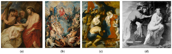
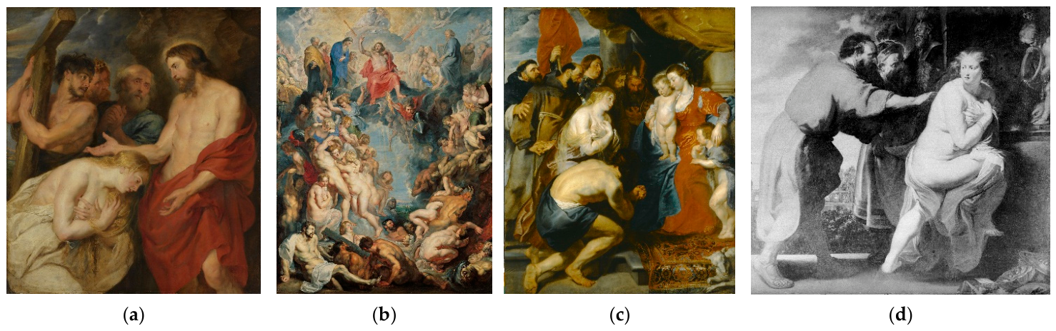
To examine the treatment of the hands and fingers, the Tokyo painting was compared with five paintings associated with Rubens dating from approximately the same period (Figure 30): The Great Last Judgement (c. 1617), The Virgin and Child with Penitent Sinners (c. 1618–1619), Christ and the Penitent Sinners (c. 1618–1620), the copy of Susanna and the Two Elders (after Rubens, c. 1617–1621), and the Tokyo painting itself.
Figure 30.
Comparative analysis of the Tokyo painting and works associated with Peter Paul Rubens. From left to right: Peter Paul Rubens, Christ and the Penitent Sinners, c. 1616–1617, oil on panel, Alte Pinakothek, Munich; Peter Paul Rubens, The Great Last Judgment, c. 1617, oil on canvas, Alte Pinakothek, Munich; Peter Paul Rubens and workshop, The Virgin and Child with St John, Worshipped by Penitent Sinners and Saints, c. 1618–1619, oil on canvas transferred to oak panel, Museumslandschaft Hessen Kassel; after Peter Paul Rubens, Susanna and the Elders, c. 1617–1621 (lost during the Second World War), formerly Picture Gallery, Sanssouci Palace, Potsdam, reproduced from a pre-1945 black-and-white photograph. These works are compared with the Tokyo painting to evaluate similarities in the depiction of hands and fingers and painterly technique. Image credits: (a,b) AMF/© bpk|Bayerische Staatsgemäldesammlungen; (c) AMF/© bpk/Hessen Kassel Heritage; (d) Rubens, Peter Paul. Werkstatt: Susanna und die beiden Alten, GK I 7573. (Verlust)/Stiftung Preußische Schlösser und Gärten Berlin-Brandenburg/Photo: Oberhofmarschallamt/ Verwaltung der Staatlichen Schlösser und Gärten (1927–1945).
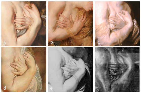
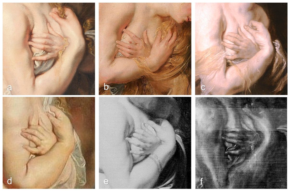
The Kassel painting, the copy of Susanna and the Two Elders, and The Great Last Judgement share broad, fleshy hands with clearly articulated first and second finger joints. By contrast, both Christ and the Penitent Sinners and the Tokyo painting display more slender, elongated fingers, in which the second joint is more strongly defined than the first (Figure 31).
Figure 31.
Comparison of the depiction of hands and fingers in works associated with Rubens and the Tokyo painting. (a) Tokyo painting; (b) Christ and the Penitent Sinners, Munich; (c) The Virgin and Child with St John, Worshipped by Penitent Sinners and Saints, Kassel; (d) The Great Last Judgment, Munich; (e) Susanna and the Elders, Potsdam; and (f) X-ray radiograph (XRR) of the Tokyo painting.
Nakamura Toshiharu [3], however, argued that the hands in the Tokyo painting reflect Van Dyck’s characteristic stylization, with weakly articulated finger joints and the omission of elongated fingernails, and therefore differ from Rubens’s treatment. The present study does not support this interpretation. Instead, the Tokyo painting closely resembles Christ and the Penitent Sinners: in both works, the fingers are elongated, the finger joints are clearly differentiated, and the fingernails are carefully defined. X-radiography (XRR) further reveals brushwork corresponding to the modeling of the finger joints and fingernail highlights, providing technical evidence consistent with these visual observations. These findings indicate that the treatment of the hands in the Tokyo painting is more closely aligned with Rubens’s pictorial practice than has previously been recognized.
The Tokyo painting also demonstrates confident brushwork characteristic of furia del pennello. Wet-in-wet handling, impasto, and feathering are employed throughout the face, hair, hands, and white drapery (Figure 22), techniques consistent with seventeenth-century Flemish workshop practice and closely comparable to works associated with Rubens and his circle.
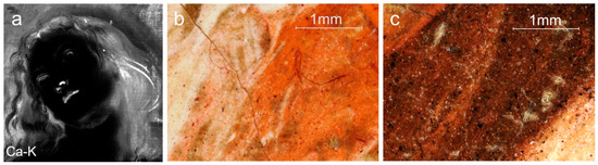
Monika Strolz [37] reported that MA-XRF analysis of Rubens’s Self-Portrait (1638–1640, Kunsthistorisches Museum, Vienna) revealed calcium-rich shadowed flesh areas, probably associated with chalk-containing mixtures, together with widespread use of vermilion in reddish flesh tones. Although comparable MA-XRF datasets from Rubens’s paintings of the same period remain scarce, the elemental distribution patterns reported by Strolz correspond closely with those observed in the Magdalene’s face, particularly the calcium-rich shadowed flesh areas (Figure 32a). Digital microscopy of the inner corner of the left eye and the slightly parted lips further reveals the fine pigment particles constituting the flesh-tone mixtures (Figure 32b,c). The inner corner of the left eye contains abundant vermilion particles, whereas the slightly parted lips contain fewer vermilion particles and correspond to an area enriched in calcium, suggesting local variations in the composition of the flesh-tone mixtures.
Figure 32.
Comparison of the elemental distribution and microscopic characteristics of the flesh tones in the face. (a) Ca-Kα elemental distribution map of the face, showing calcium-rich areas corresponding to the shadowed flesh tones. (b) DMI of the inner corner of the left eye (location E in Figure 4), ×90 magnification, (c) DMI of the slightly parted lips (location G in Figure 4), ×90 magnification.
4.5. Synthesis, Attribution, and Art-Historical Implications
Overall, the material, technical, and imaging evidence presented in the preceding sections provides a coherent framework for reassessing the authorship of the Tokyo painting. The materials, layer structure, and painting techniques are fully consistent with seventeenth-century Flemish painting practice, particularly in the use of lead white, azurite, copper-based green pigments, earth pigments, lead-tin yellow, and yellow lake pigments. These features correspond closely with materials and techniques documented in works associated with both Rubens and Van Dyck. While the possible presence of lapis lazuli cannot be established conclusively on the basis of the current evidence, its use cannot be excluded and remains a subject for further investigation.
Comparison of the Tokyo painting, reconstructed to approximate its original appearance before later repainting, with Titian’s Penitent Magdalene and Cornelis Cort’s engraving after the composition reveals numerous compositional and formal correspondences. In particular, the correspondence with the Capodimonte version is especially close, suggesting not only familiarity with Titian’s work but also a deliberate and informed engagement with it. At the same time, technical examination indicates that the valley area was subsequently repainted, a modification that appears to have reduced the painting’s resemblance to the original composition. Rather than indicating straightforward imitation, this alteration is more plausibly interpreted as evidence of an evolving creative process.
Taken together, the evidence provides no basis for excluding either Rubens or Van Dyck from consideration. However, the cumulative material, technical, and compositional evidence presented in this study suggests that the longstanding preference for a Van Dyck attribution should be reconsidered. Several features identified through the present investigation—including the treatment of the figure, the painterly execution, the compositional development, and the close affinities with works associated with Rubens—support renewed consideration of Rubens as a plausible author of the Tokyo painting.
5. Conclusions
This study has demonstrated that the materials, layer structure, and painting techniques of the Tokyo painting are fully consistent with seventeenth-century Flemish painting practice. The integration of non-invasive imaging and analytical methods has clarified the painting’s material composition, execution, and conservation history, providing an objective technical foundation for reassessing its authorship.
The technical and art-historical evidence presented in this study provides no basis for excluding either Rubens or Van Dyck from consideration. However, the cumulative evidence suggests that the longstanding preference for a Van Dyck attribution should be reconsidered and supports renewed consideration of Rubens as a plausible author of the Tokyo painting.
More broadly, this study demonstrates the value of integrating non-invasive imaging with material analysis in the investigation of authorship. In particular, MA-XRF has proven to be a powerful tool for visualizing elemental distributions and informing art-historical interpretation. Wider availability of comparable analytical datasets will facilitate future comparative research and contribute to more robust attribution studies.
Supplementary Materials
The following supporting information can be downloaded at: https://www.mdpi.com/article/10.3390/heritage9080324/s1. Supplementary Figure S1. Digital microscopy images from the locations indicated in Figure 4. The images are labeled A, B, C, D, E, F, G, H, J, L, N, O, R, S, U, and W, corresponding to the respective locations in Figure 4. All images were acquired at 90× magnification. The scale bar is shown only in the image labeled A and applies to all images. Supplementary Figure S2. Normalized visible and near-infrared reflectance spectra acquired from the locations indicated in Figure 4. The six plots show spectra from the following locations, respectively: Locations A, B, C; Locations D, F, H; Locations I, J; Locations K, L, M, N; Locations P, Q, R, S; and Locations T, U, V, W. The uppercase letters correspond directly to the locations indicated in Figure 4. All spectra are normalized for comparison. Supplementary Figure S3. Normalized visible and near-infrared reflectance spectra of the reference pigments listed in Table 1. The four plots show spectra of the following pigments, respectively: Pigments 1: Blue Verditer, Smalt, Indigo, and Verdigris; Pigments 2: Azurite, Malachite, Lapis lazuli, and Copper resinate; Pigments 3: Yellow ochre, Indian red, Lead-tin yellow, and Stil de Grain; and Pigments 4: Vermilion, Red lead, and Madder lake. All spectra are normalized for comparison.
Funding
This research received no external funding.
Data Availability Statement
All data supporting the findings of this study are available from the corresponding author upon reasonable request.
Acknowledgments
The author sincerely thanks the private owner of the painting for granting access to the work, permitting its scientific examination, and authorizing publication of the analytical data and this paper. The author is deeply grateful to Tsuchiya, Y., Tsukada. for their invaluable advice and insightful comments throughout this research, and to Hirakawa, K. and Fukaya, M. for many stimulating discussions and valuable suggestions. Grateful acknowledgement is also extended to the museums and cultural institutions that kindly granted permission for the reproduction of images included in this publication. Bruker Japan Co., Ltd., IR System Co., Ltd., Hirox Co., Ltd., Tokyo University of the Arts, Terrada Art Assist Conservation and Restoration Laboratory, and I-Art Co., Ltd. are gratefully acknowledged for providing access to the analytical equipment and facilities used in this study. Finally, the author wishes to pay profound tribute to the late Toshiharu Nakamura, the Western art historian who carried out the first comprehensive scholarly study of this painting in Japan.
Conflicts of Interest
The author declare no conflict of interest.
Note
| 1 | The symbol □ denotes an illegible or missing character. |
References
- Agnew, J. Anthony van Dyck: Catalogue of the Exhibition; Agnew’s Gallery: London, UK, 1968. [Google Scholar]
- Nakamura, T. The Former Joseph Robinson Collection: Anthony van Dyck, The Penitent Magdalene. Kyoto J. Aesthet. Art Hist. 2012, 11, 191–216. [Google Scholar]
- Nakamura, T. The penitent Magdalene from the former Joseph Robinson Collection—Young Van Dyck working up Rubens’s conception. In Reframing Jordaens; Michael Imhof Verlag: Petersberg, Germany, 2019. [Google Scholar]
- Nakamura, T. Rubens: Inspired by Italy and Established in Antwerp; Exhibition catalogue; Bunkamura: Tokyo, Japan, 2013. [Google Scholar]
- Legrand, S.; Vanmeert, F.; Van der Snickt, G.; Alfeld, M.; De Nolf, W.; Dik, J.; Janssens, K. Examination of historical paintings by state-of-the-art hyperspectral imaging methods: From scanning infra-red spectroscopy to computed X-ray laminography. Herit. Sci. 2014, 2, 13. [Google Scholar] [CrossRef] [Scilit]
- Alfeld, M.; Laurenze-Landsberg, C.; Denker, A.; Janssens, K.; Noble, P. Neutron activation autoradiography and scanning macro-XRF of Rembrandt van Rijn’s Susanna and the Elders: A comparison of two methods for imaging of historical paintings with elemental contrast. Appl. Phys. A 2015, 119, 795–805. [Google Scholar] [CrossRef] [Scilit]
- Cucci, C.; Delaney, J.K.; Picollo, M. Reflectance hyperspectral imaging for investigation of works of art: Old master paintings and illuminated manuscripts. Acc. Chem. Res. 2016, 49, 2070–2079. [Google Scholar] [CrossRef] [Scilit] [PubMed]
- de Viguerie, L.; Rochut, S.; Alfeld, M.; Walter, P.; Astier, S.; Gontero, V.; Boulc’h, F. XRF and reflectance hyperspectral imaging on a 15th century illuminated manuscript. Herit. Sci. 2018, 6, 11. [Google Scholar] [CrossRef] [Scilit]
- Pease, M. Some thoughts on the scientific examination of paintings. Stud. Conserv. 1959, 4, 61–70. [Google Scholar]
- Millar, O. A note on a painting attributed to Van Dyck. Burlingt. Mag. 1968, 110, 632–634. [Google Scholar]
- Müller Hofstede, J. Des Sünders reuige Seele: Der Bußeraltar von Rubens in der Kasseler Gemäldegalerie. In Rubens in Seiner Zeit; Mai, E., Ed.; Rheinland-Verlag: Pulheim, Germany, 1983; pp. 243–260. [Google Scholar]
- Jaffé, M. Oral statement on the attribution of the painting to Van Dyck. In Rubens in Seiner Zeit; Mai, E., Ed.; Rheinland-Verlag: Pulheim, Germany, 1983; p. 226. [Google Scholar]
- Barnes, S.; De Poorter, N.; Millar, O.; Vey, H. Van Dyck: A Complete Catalogue of the Paintings; Yale University Press: New Haven, CT, USA, 2004. [Google Scholar]
- Van der Snickt, G.; Legrand, S.; Slama, I.; Van Zuien, E.; Gruber, G.; Van der Stighelen, K.; Klaassen, L.; Oberthaler, E.; Janssens, K. In situ macro X-ray fluorescence (MA-XRF) scanning as a non-invasive tool to probe for subsurface modifications in paintings by P.P. Rubens. Microchem. J. 2018, 138, 238–245. [Google Scholar] [CrossRef] [Scilit]
- Mazzinghi, A.; Ruberto, C.; Castelli, L.; Czelusniak, C.; Giuntini, L.; Mandò, P.A.; Taccetti, F. MA-XRF for the characterisation of the painting materials and technique of the Entombment of Christ by Rogier van der Weyden. Appl. Sci. 2021, 11, 6151. [Google Scholar] [CrossRef] [Scilit]
- de Viguerie, L.; Glanville, H.; Radepont, M.; Cerasuolo, A.; Rullo, A.; Seccaroni, C.; Walter, P. An investigation of Bellini’s TransFigureuration in the Capodimonte museum by means of XRF and visible reflectance hyperspectral imaging. Herit. Sci. 2013, 11, 163. [Google Scholar]
- Gabrieli, F.; Delaney, J.K.; Erdmann, R.G.; Gonzalez, V.; van Loon, A.; Smulders, P.; Berkeveld, R.; van Langh, R.; Keune, K. Reflectance imaging spectroscopy (RIS) for Operation Night Watch. Sensors 2021, 21, 6855. [Google Scholar] [CrossRef] [Scilit]
- Kamba, N. A comparison of three versions of The Flight of Lot and his Family from Sodom. In Rubens and His Workshop—The Flight of Lot and His Family from Sodom; Nakamura, T., Ed.; Insho-Sha: Tokyo, Japan, 1994; pp. 69–96. [Google Scholar]
- Gruber, G.; Van der Katlijne, S.; Elke, O.; Van der Geert, S.; Wien, K.M.; Koen, J. Rubens’s portrait of Helena Fourment: Some hidden aspects of The Fur. In Point of View; KHM-Museumsverband: Vienna, Austria, 2015; p. 13. [Google Scholar]
- Eastaugh, N.; Walsh, V.; Chaplin, T.; Siddall, R. The Pigment Compendium Optical Microscopy of Historical Pigments; Elsevier: Amsterdam, The Netherlands, 2004; pp. 362–369. [Google Scholar]
- Gipbet, M.; Carvalho, M.L.; Seruya, A.; Candeias, A.E.; Mirão, J.; Queralt, I. Yellow and red ochre pigments from southern Portugal: Elemental composition and characterization by WDXRF and XRD. Nucl. Instrum. Methods Phys. Res. 2007, 580, 728–731. [Google Scholar] [CrossRef] [Scilit]
- Derks, K.; Van der Snickt, G.; Legrand, S.; Van der Stighelen, K.; Janssens, K. The dark halo technique in the oeuvre of Michael Sweerts and other Flemish and Dutch Baroque painters: A seventeenth-century empirical solution to mitigate the optical “simultaneous contrast” effect? Herit. Sci. 2022, 10, 5. [Google Scholar] [CrossRef] [Scilit]
- Van Loon, A.; Speleers, L. The use of blue and green verditer in green colours in the mid-seventeenth century paintings of the Oranjezaal, The Hague. In Studying Old Master Paintings: Technology and Practice; Spring, M., Ed.; Archetype Publications: London, UK, 2011; pp. 260–268. [Google Scholar]
- Van Hout, N.; Balis, A. Notes on the masters’ painting technique. In Rubens Unveiled; Ludion: Ghent, Belgium; Antwerp, Belgium, 2012. [Google Scholar]
- Harth, A.; Van der Snickt, G.; Schalm, O.; Janssens, K.; Blanckaert, G. The young Van Dyck’s fingerprint: A technical approach to assess the authenticity of a disputed painting. Herit. Sci. 2017, 5, 22. [Google Scholar] [CrossRef] [Scilit]
- Roy, A. The National Gallery Van Dycks: Technique and development. Natl. Gallery Tech. Bull. 1999, 20, 50–83. [Google Scholar]
- David, J.; Hark, R.; Town, E. “A real master among hundreds”: The secrets and techniques of seventeenth-century portraiture in Britain. Materia 2017, 1, 6–27. [Google Scholar]
- Alba, L.; Jover, M.; Gayo, M.D. Introduction to the technical studies. In The Young Van Dyck; Vergara, A., Lammertse, F., Eds.; Thames & Hudson: London, UK, 2012; pp. 337–377. [Google Scholar]
- Kirby, J. The painter’s trade in the seventeenth century: Theory and practice. Natl. Gallery Tech. Bull. 1999, 20, 5–49. [Google Scholar]
- Schianchi, L.; Spinosa, N. Tiziano 33. La Maddalena. In IFarnese Arte e Collezionismo; Electa: Milan, Italy, 1995; pp. 217–219. [Google Scholar]
- Muller, J.M. Rubens: The Artist as Collector; Princeton University Press: Princeton, NJ, USA, 1989. [Google Scholar]
- Freedberg, D.A. Rubens and Titian: Art and politics. In Titian and Rubens: Power, Politics, and Style; Goldfarb, H.T., Freedberg, D.A., Mena Marqués, M.B., Eds.; Isabella Stewart Gardner Museum: Boston, MA, USA, 1998; pp. 29–66. [Google Scholar]
- Wood, J. The problem of the portrait copies painted by Rubens in Madrid, 1628–1629. Burlingt. Mag. 1992, 134, 192–200. [Google Scholar]
- Vlieghe, H. Une grande collection anversoise du dix-septième siècle: Le cabinet d’Arnold Lunden, beau-frère de Rubens. Jahrb. Berl. Mus. 1977, 19, 172–204. [Google Scholar] [CrossRef] [Scilit]
- Belkin, K.L.; Healy, F.; Muller, J.M.; Martin, G. A House of Art: Rubens as Collector; Rubenshuis: Antwerp, Belgium, 2004. [Google Scholar]
- Muller, J.M. Rubens’s Cupids and Andrians: The first documents and what they tell us. In Bacchanals by Titian and Rubens; Cavalli-Björkman, G., Ed.; Nationalmuseum: Stockholm, Sweden, 1987; pp. 75–80. [Google Scholar]
- Strolz, M. Appendix II: Technical examination of Rubens’s last self-portrait. In Rubens in Private: The Master Portrays His Family; Van Beneden, B., Ed.; Thames & Hudson: London, UK, 2015. [Google Scholar]




Disclaimer/Publisher’s Note: The statements, opinions and data contained in all publications are solely those of the individual author(s) and contributor(s) and not of MDPI and/or the editor(s). MDPI and/or the editor(s) disclaim responsibility for any injury to people or property resulting from any ideas, methods, instructions or products referred to in the content. |
© 2026 by the author. Licensee MDPI, Basel, Switzerland. This article is an open access article distributed under the terms and conditions of the Creative Commons Attribution (CC BY) license.