


Abstract
Masonry buildings belonging to the architectural heritage are often characterized by the presence of masonry arches, vaults, and domes. A thorough structural assessment of masonry vaults is essential from a conservation perspective, as these elements are often subject to damage, cracks, and, in some cases, collapse. In the literature, the structural behaviour of the most common vault types has been extensively investigated using a broad blend of techniques capable of capturing significant aspects of the complex behaviour of masonry. However, for some less common vault typologies, a comprehensive understanding of their structural response remains an open issue. In this multifaceted context, the present contribution aims to investigate the structural behaviour of a distinctive type of vault, namely the umbrella vault, in which a series of webs are arranged in an umbrella-like configuration. To this end, an iconic case study is selected for its geometric complexity, namely the umbrella vault of Masegra Castle (northern Italy). Peculiar aspects are manifold, the most important being the irregularity of the quadrangular plan. The analysis focused on the structural response of the vault under self-weight, in the presence and absence of supporting walls. During the modelling phase, an interdisciplinary approach was adopted, integrating historical and diagnostic information. Starting from the available data, the study proposes nonlinear finite element analyses, discussing the most appropriate modelling strategies, based on solid or plate/shell finite elements, and performing sensitivity analyses on the mesh used and the vault thickness.
1. Introduction
The conservation of architectural heritage is worldwide considered a priority, as many historic buildings are subjected to material and structural decay, accelerated by rising temperatures, humidity extreme fluctuations, floods, etc. Cultural heritage protection is a tricky objective that can only be achieved through consistent, coordinated, and planned research, prevention, maintenance, restoration [1] and an interdisciplinary approach is considered mandatory [2,3]. The conservation of built heritage poses increasingly complex challenges, aimed at reconciling conflicting aspects: protecting the building’s historical, artistic, and cultural values; adapting it to contemporary needs, both in terms of new uses and comfort; and complying with regulations regarding safety, accessibility, energy efficiency, and the environment [4].
In such a complex scenario, this work focuses on a deep understanding of the structural behaviour of a peculiar class of masonry vaults, as detailed below. With respect to the objectives of architectural heritage conservation, this research area aims to provide elements to support expert judgment to outline a picture of the areas most subject to stress, which can be qualitatively linked to the onset of a crack pattern.
As is known, the study of the mechanical behaviour of masonry is a complex issue, since masonry is characterized by inhomogeneity, low tensile resistance, finite compressive strength, anisotropy [5] and preferential propagation of cracks along mortar joints. In the scientific literature, various methods are used to gain an adequate understanding of the structural response of masonry structures, depending on the objectives of the research carried out. Without claiming completeness, within the context of limit analysis and starting from the seminal contribution by Heyman [6,7], masonry structures have been studied by idealizing masonry as a material unable to withstand tensile stresses, with an ideally unlimited compressive strength and infinite friction resistance, so that sliding is prevented [8,9]. The theoretical framework proposed by Heyman enabled the analysis of the response of masonry structures using the static [10,11,12,13,14,15,16,17] or kinematic [18,19,20,21] theorem of limit analysis, while extending the hypotheses by considering the presence of finite friction [22,23,24,25] and/or compressive strength [26,27,28,29].
More refined modelling techniques are based on classic finite element discretization, adopting macro-modelling approaches, which assume that masonry behaves as an equivalent homogeneous material [30,31,32], or micro-modelling, i.e., with a distinct representation of joints and bricks [33,34], which generally require high computational effort. In this context, the scientific literature includes contributions aimed at studying the structural response of masonry structures in service conditions, with the aim of establishing possible strengthening interventions [35], as well as research proposing simplified approaches [36] or methods for the assessment of collapse conditions [37]. Another promising numerical approach is based on the discrete element method (DEM), first conceived by Cundall [38], a well-known technique for modelling a variety of mechanical problems, including the structural response of masonry structures [39,40,41].
While simplified approaches can make it difficult to capture some aspects of the mechanical behaviour of masonry structures, more refined models often require significant computational resources and knowledge of numerous parameters that must be properly calibrated. If these parameters are difficult to determine, even the most sophisticated numerical approaches are unlikely to predict the actual structural response.
In this complex context, a further issue arises when the object of investigation is atypical. While numerous studies exist on the structural response of some common vault types, others have received very limited attention in the literature.
This is the case of umbrella vaults, the subject of this research, frequently found in 16th-century Italian architecture. Such vault typology is characterized by a geometry divided into webs that converge toward the centre of the intrados. The intersection of these webs gives the structure the appearance of an open umbrella (Figure 1a). Some umbrella vaults have a polygonal base, but numerous variations exist. They can be inserted into rectangular spaces with the addition of lunettes, divided in half, for example in the apses of cathedrals, or enlarged by adding webs in the central region. From a historic perspective, it is interesting to note that, despite its peculiarity, the umbrella vault is often described as a variant of more common vault typologies (cross vaults, cloister vaults, stellar vaults) [42,43].
Figure 1.
Umbrella vault of Masegra Castle (Sondrio, Italy). (a) 3D model of the vault in Rhino 7; (b) intrados of the vault (photo by D.A.).
This paper aims to deepen our understanding of the structural behaviour of umbrella vaults, subjected to self-weight, by examining an interesting case study, the umbrella vault of Masegra Castle (Sondrio, Italy), characterized by eight interconnected webs and an irregular quadrangular perimeter (Figure 1b).
On the one hand, the interest of this contribution lies in the complex geometry of the object under examination and in the development of nonlinear finite element analyses that, for the first time, highlight the peculiarities of the mechanical behaviour of umbrella vaults under their own weight. On the other hand, when compared with previous research on the same vault [42,43,44,45,46,47,48,49,50], this work presents several innovative aspects. Indeed, analysing the umbrella vault under self-weight enables the interpretation of some cracking features related to the low masonry tensile strength. Moreover, the investigation aims to highlight some peculiar aspects of the structural response as thickness varies, providing a workflow that can be applied to vaults of the same typology.
As explained in Section 3.2, in this work the brittle mechanical behaviour of masonry is modelled using the Concrete Damage Plasticity model implemented in the commercial finite element code Abaqus CAE 2024 [51]. This model does not track individual “macro” cracks; instead, constitutive calculations are performed independently at each integration point of the FE model. The presence of cracks is accounted for in these calculations through their effect on the stress state and material stiffness associated with each integration point. This remark should be kept in mind throughout the remainder of the paper whenever real observed cracks are compared with predicted damaged zones.
2. Vault Description and Previous Studies
Situated on the first floor of Sondrio Castle’s dovecote tower, the umbrella vault under consideration overlooks a magnificent camera picta.
The castle’s complex evolution can be traced back to both political and historical factors, as well as to its location, which made it a place of strategic importance. From 1434 to 1477, the castle was governed by the noble Beccaria family. During this period, it began to lose its military function and was gradually transformed into a noble residence. With reference to the camera picta, it is worth recalling that magnificent frescoes of significant artistic value adorn the intrados of the vault, depicting Ariosto’s cycle, a recurring motif in 15th-century noble palaces, which testify to the prestige of the Beccaria family. Although the castle’s use as a military headquarters in later centuries did not enhance the presence of this vault, the room it covered must have originally been a very bright and colourful space.
Given the presence of an extensive and significant network of cracks in the southern wing of the castle, as well as the Municipality of Sondrio’s desire to restore this site of great cultural interest, research into the conservation and the structural assessment of the castle has been carried out in recent years [42,43,44,45,46,47,48,49,50].
The entire castle was laser-scanned between 2014 and 2015, using a FARO Focus3D scanner, whose ranging accuracy is in the order of a few millimetres [42,43,44,45]. The post-processing activity—point cloud registration, cleaning, segmentation, and modelling—required a significant amount of work. Photogrammetry was also used to combine the geometric survey with data from particular areas deemed of interest. The primary objective was to incorporate these data into a BIM model to support the monitoring of masonry deterioration and the visualization of the precise arrangement of specific architectural elements. The transition from the measured geometry to the NURBS/FEM model involves numerous transformations. References [42,43,44,45] describe in detail the process of moving from the point cloud to the definition of the NURBS model, utilizing the point cloud management tools provided by AutoCAD 2015 software. The shape of the vault was defined using curves (splines) characterized by a limited number of control points, thereby avoiding the replication of every micro-irregularity—often caused by unevenness in the surface plaster layer. The profiles obtained in the studies just mentioned were exported to Rhino 7 and served as the starting point for our work.
Furthermore, diagnostic analyses were performed [42,43,44,45]. Non-destructive testing included psychrometric, gravimetric, and microclimate monitoring of both the interior and exterior spaces. For the analysis of the structural behaviour of the vault and the entire castle, thermography—applied both actively and passively—proved to be one of the most important methods. Thermographic inspection provided insight into the castle’s structure, identified hidden deterioration, and allowed the assessment of moisture and temperature conditions in the superficial masonry layers. To estimate the compressive strength and deformability of masonry, in situ flat-jack tests were carried out.
The camera picta enclosed by the umbrella vault and the southern tower, also known as the dovecote tower, were specifically examined. The crack pattern affecting the umbrella vault and the walls of the camera picta represents one of the most significant structural issues in the castle. This situation is most likely the result of several factors that caused the east wall of the room to settle. Among these, we can mention the lack of adequate foundations, confirmed by core sampling tests carried out during on-site investigations. The southern part of the castle initially consisted of only a few ground-floor spaces, and the foundations were probably designed to withstand the corresponding loads. However, when the dovecote tower was extended by two additional floors, the foundations may have become inadequate. Another contributing cause of possible settlements was the construction of a large building during the period in which the castle was used as a military district (18th century), adjacent to the dovecote tower. The above-mentioned aspects underscore the importance of fully understanding the history of the castle, as is the case for most heritage buildings, as well as the development of its individual units, to formulate plausible hypotheses regarding settlement causes and the resulting crack pattern.
From a structural point of view, some previous research on the vault of Masegra Castle [42,43,44,45] has focused on re-elaborating laser-scanner survey data, available as dense point clouds, to develop an accurate Building Information Model of the historical building (HBIM) and, subsequently, a finite element model. In the finite element analyses, the material comprising the vault is assumed to be linear elastic. Compared with these contributions, the present study aims to take a step forward by performing nonlinear finite element analyses, thereby introducing the complexity of masonry behaviour into the model. Furthermore, earlier research was conducted on this umbrella vault with the aim of identifying the causes of the observed crack pattern. Attention has focused on studying the effects of ground settlements, which involve not only the vault but also the side walls, in order to formulate a diagnosis, which represents the first and fundamental step before designing an appropriate intervention. To provide a numerical understanding of the cracking pattern found in the umbrella vault, [46,47,48] use an adaptive NURBS (Non-Uniform Rational B-Splines) kinematic limit analysis to determine the structural response in the presence of differential settlements in the supports, starting from the HBIM model. The problem is framed in the upper bound theorem, according to the simplifying assumptions proposed by Heyman [6,7]. The vault is discretized into a small number of infinitely resistant NURBS elements. Detachment is allowed only along the interfaces between adjacent blocks. Compared to these latter contributions, the nonlinear analyses proposed here do not require a priori discretization of the vault into macro-elements capable of plausibly replicating the cracking pattern, but directly highlight the regions of the vault subject to greater stresses. Further research on the effects of vertical settlements has been conducted in [49,50], where both the vault and the surrounding walls are considered. With respect to these contributions, the investigation presented here, by further developing the nonlinear approach proposed in [49,50], aims to understand the behaviour of the umbrella vault under its own weight in order to offer useful information for interpreting the configuration of the cracks depending on the shape of the vault.
Despite the asymmetry in the crack pattern—also due to the aforementioned ground subsidence—it is possible to clearly identify two families of cracks in the vault, which cannot be attributed solely to ground subsidence problems, but reflect the structural response of the umbrella vault due to its geometry (see Figure 2): a first set, hereafter referred to as ‘radial,’ consisting of cracks that originate from the corners or the centre of the webs and develop toward the centre of the vault, and a second type consisting of circumferential cracks, which develop along circumferences centred at the top of the vault.
Figure 2.
Umbrella vault of Masegra Castle (Sondrio): three-dimensional model of the intrados crack pattern; see the red lines (image by N. Grillanda; from [48]).
3. From Geometrical and Experimental Data to Finite Element Analyses
3.1. Three-Dimensional Model of the Umbrella Vault in Masegra Castle
Having precise geometric data is essential for developing structural models capable of reliably reproducing the mechanical response of historic buildings. In the case of the umbrella vault of Masegra Castle while the geometry of the intrados was accurately surveyed, the vault thickness remained unknown. This is because the extrados is inaccessible and indirect inspection techniques cannot be applied. Furthermore, any direct inspection would be impractical due to the presence of valuable frescoes.
To address this lack of information, a comparative approach was adopted based on the analysis of existing documentation concerning other vaults within the castle that were built during the same period, namely between 1434 and 1477. During this time, a loggia was added to the north side of the castle to give the building the appearance of a noble residence rather than a military stronghold. Direct thickness measurements were carried out on two of the vaults of the loggia by removing a portion of the flooring and excavating the fill material down to the load-bearing structure. Subsequently, the difference between the surveyed points of the intrados and extrados was determined using point clouds, thus avoiding the need to drill holes in the vaults. These investigations showed that the loggia vaults are built of large stone blocks and have a thickness of approximately 20 cm [42,43]. Based on these findings, in the present study it is assumed that the umbrella vault under investigation has the same material and thickness as the loggia vaults, since it is contemporary with them and has a comparable span (approximately 4 m). The modelling process begins with a 3D Rhino model of the vault intrados, represented by NURBS surfaces derived from previous studies [42,43,44,45], which provided a selection of control points from the raw point cloud. Due to the difficulties encountered when directly applying the ExtrudeSrf command (which creates a solid from the original object by specifying the tolerance, extrusion direction, and distance between the top and bottom surfaces), it was necessary to redraw more accurately the two webs of the vault intrados that exhibited the most significant discontinuities, based on the original wireframe geometry, without modifying the overall surveyed shape. The procedure, carried out in Rhino 7, involved extracting the wireframe geometry of each web and using the Patch command to generate new surfaces by selecting both the wireframe curves and the edges of the adjacent webs. This operation produced geometries that maintained correspondence with the wireframe lines used as model inputs, while ensuring proper continuity with the neighbouring surfaces. Since each web was represented by a separate NURBS surface, the Join command was subsequently used to create a single continuous intrados object. The Offset command was then applied using the Round option, which fills the gap between adjacent offset segments with tangent arc surfaces. This operation generated a closed polygonal surface and, subsequently, a solid 3D volume. To obtain a geometry compatible with fixed boundary conditions at the interface with the surrounding tower walls, four vertical cutting planes, one for each side, were introduced to remove the irregularities generated by the offset operation (Figure 1a). The resulting model was exported as a .sat file and imported into Abaqus CAE 2024 as separate components. After correcting the remaining geometrical imperfections using the Geometry Edit tool, the two components were merged into a single solid volume within the Assembly module. It should be observed that the resulting surface incorporates the exact points used as input data.
3.2. Implementation of the Concrete Damage Plasticity (CDP) Model in Abaqus CAE
The Finite Element analyses of the vault are carried out in Abaqus CAE 2024. To accurately describe the inelastic mechanical behaviour of masonry, the Concrete Damage Plasticity (CDP) is adopted [51]. This constitutive model combines the concepts of damaged elasticity with tensile and compressive plasticity.
Under uniaxial tension, the stress–strain response is linear elastic up to the failure stress, , which corresponds to the onset of microcracking in the material. Beyond this stress level, the formation and propagation of microcracks are macroscopically represented by a strain-softening law. To mitigate the mesh dependency associated with strain localization, the tensile behaviour is defined through a stress–displacement law; therefore, the fracture energy is prescribed, as discussed later. Material degradation is accounted for within the constitutive framework of the CDP model. A scalar tensile damage variable () is introduced to describe the progressive loss of load-bearing capacity due to cracking under tension. Compressive (crushing) damage is neglected in the present case study, for the reasons discussed later. The damage variable ranges from 0 (corresponding to an undamaged material) to 1 (corresponding to complete loss of stiffness).
The stress–strain relationship under uniaxial tension is given by:
where is the elastic stiffness of the undamaged material, is the total strain, and denotes the equivalent plastic strains. The damage variable is defined as a function of the plastic strain.
The Drucker–Prager hyperbolic function is adopted as the flow potential G in the CDP model:
where q is the equivalent deviatoric stress and is the hydrostatic pressure. The parameter is the dilation angle, while is the eccentricity parameter.
The yield function defines the stress domain within which the material behaves elastically. In the deviatoric plane, it can be represented as a closed surface whose shape is controlled by the parameter allowing a better fit to the experimental behaviour. In the CDP model, the yield criterion proposed by Lubliner et al. [52] is adopted, with the modifications introduced by Lee and Fenves [53] to account for the different evolution of tensile and compressive strength. According to these references, additional parameters are required to define the CDP model in Abaqus CAE: the ratio between the equi-biaxial compressive strength and the uniaxial compressive strength, , and a viscosity parameter introduced to improve the convergence of the numerical analysis.
In the CDP model, it is also necessary to define the isotropic elastic properties used in the analyses. With reference to previous studies on the umbrella vault [46,47,49,50], the material density, ρ, is assumed to be 2200 kg/m3, in accordance with the Italian Building Code [54], since the vault is considered to be constructed of stone masonry composed of large blocks. Furthermore, the Poisson’s ratio is assumed to be 0.2, a typical value for quasi-brittle materials such as concrete and mortar.
The value of the elastic modulus is more difficult to define. In the present study, it is based on the reference value of 3000 MPa reported in [54] as well as on mechanical tests conducted in the south wing of the castle, in a portion built in the same time as the umbrella vault. The measured elastic modulus values were 2500 MPa for the first loading-unloading cycle, and 3000 MPa for the second cycle [42,43,44,45,47].
Considering previous studies on the modelling of masonry structures with the CDP model [37,55,56,57], a uniaxial compressive strength is assumed. In Table 3.1 of CNR-DT 212/2013 [58], a similar value is reported for rough ashlar masonry. In cases of uncertainty regarding the specific characteristics of the material, according to the Italian standards [54] the assumed properties of masonry depend on the “level of knowledge”, which is linked to the so-called confidence factor. In view of the above, and in the absence of detailed information, such a compressive strength value was also selected for safety reasons. Since the material is expected to remain well below its compressive limit under service loads, an elastic–perfectly plastic stress–strain law in compression is adopted (Figure 3a). The tensile strength, , is set to 0.05 MPa, i.e., approximately 2% of the compressive strength. The fracture energy, , is set to 10 N/m to represent the brittle behaviour of masonry. More precisely, the tensile strain-softening branch is assumed to be linear (Figure 3b).
Figure 3.
Concrete Damage Plasticity (CDP) model in Abaqus CAE: (a) elastic–perfectly plastic stress–strain law in compression; (b) stress–displacement curve in tension (linear softening).
Before proceeding further, it is worth noting that, although the CDP model can accurately reproduce some aspects of the actual behaviour of masonry, selecting the values of the parameters defining the model is not an easy task, owing to the extreme variability of masonry properties, even within the same structure. Furthermore, mortar joints in brick or stone masonry act as planes of weakness, making the material macroscopically anisotropic.
In the present study, an isotropic constitutive law is adopted, owing to the lack of suitable anisotropic nonlinear constitutive models implemented in the available FE software (Abaqus CAE 2024). For the purposes of this article, the material parameters of the CDP model were taken from the literature on historical masonry structures [37,55,56,57]. A more rigorous calibration of the adopted parameters, together with a sensitivity analysis of their individual effects, is beyond the scope of this work. The interested reader is referred to [59], where a sensitivity analysis of the CDP parameters is conducted using reference values derived from shear tests on masonry panels. The study carried out in [59] highlights the complexity of interpreting the analysis results, which represents a significant challenge in modelling masonry structures.
Considering the above, and acknowledging the limitations associated with these aspects, the CDP parameters employed in the present study are not intended to definitively describe the behaviour of the actual material. Rather, they are considered plausible and consistent with the scientific literature on the subject.
Table 1 summarizes the CDP parameters adopted, as well as the mechanical properties of the materials used in the numerical modelling of the vault.
Table 1.
CDP Model parameters and mechanical properties of the material adopted in the numerical modelling of the umbrella vault.
To define tensile damage in the Abaqus CDP model, the ultimate displacement must be evaluated, i.e., the displacement at which the material reaches failure under tensile loading. The displacement at the end of the elastic branch in tension is given by
where is the characteristic crack length of the finite element. Abaqus computes Lc as the cubic root of the element volume for linear elements, or as half of this value for quadratic elements. Therefore, Lc is related to the characteristic element length h, which is taken as 20, 10 or 5 cm in the applications presented in Section 4. The final displacement, , is
where is the ultimate cracking displacement derived from the material’s fracture energy, , and the uniaxial tensile stress at failure, .
Table 2 shows the stresses and the corresponding displacements for different characteristic element lengths. In the numerical implementation, the maximum value of the parameter (labelled as DAMAGET in Abaqus) is set to 0.99 to prevent numerical instability. Indeed, when the material is fully damaged, its stiffness tends to zero and convergence problems may occur. The final displacements reported in Table 2 are therefore taken as the maximum values.
Table 2.
3D elements: tensile damage: stress–displacement data for different characteristic finite element lengths.
It should be finally noted that the concept of tensile damage, although related to crack initiation, indicates a degradation of stiffness and therefore does not directly represent the width or opening of a well-defined crack.
4. Finite Element Analysis of the Umbrella Vault Subjected to Gravitational Loads
4.1. Sensitivity Analysis
Because of the lack of numerical studies on umbrella vaults, a preliminary mesh sensitivity analysis was performed to investigate how the structural response of the vault predicted by the Finite Element Method varies with the type and size of the elements.
The objective is to identify the most suitable finite elements for these types of masonry vaults, with the possibility of extrapolating the findings obtained for the case study to similar structures. In this context, particular attention was devoted to determining the appropriate average element size, as well as to assessing the stability of the procedure and the rate at which a converged response is achieved.
Two main strategies, typical of the finite element method FEM, were used to verify convergence: h-convergence, which consists of reducing the characteristic elements size, h, and p-convergence, which consists of increasing the order of the polynomial functions, denoted by “p.” In Abaqus CAE 2024, only linear and quadratic shape functions are available for 3D solid elements.
Tetrahedral and hexahedral finite elements can generally be used for three-dimensional geometries. Due to their complex shape, auto-meshing is the most viable to obtain rapidly a suitable discretization, so tetrahedral elements are best suited for umbrella vaults. Solid elements were preferred over shell elements because a more complex analysis of the entire building, or of parts thereof, would require the discretization of the massive perimeter walls. Unlike the vault, these walls cannot be adequately represented using shell elements.
To perform the sensitivity analysis, both linear and quadratic tetrahedral elements were employed, labelled C3D4 and C3D10 in Abaqus CAE 2024, respectively. The C3D4 is a four-node finite element with linear interpolation of the displacements and constant stress, where for the analyses a single Gaussian integration point is used. The C3D10 is a 10-node element with quadratic interpolation of the displacements and linear variation in the stresses, where a four-point Gaussian integration scheme is adopted. For each element type, meshes with three different characteristic element sizes were tested: h = 20, 10 and 5 cm. Given the above, a total of six cases were considered, as reported in Table 3. Regarding the notation used to identify the different cases, “L” indicates linear finite elements and “Q” indicates quadratic finite elements; the following number indicates the characteristic element size, in cm.
Table 3.
3D elements: mesh sensitivity analysis; the six cases under examination (FE analyses conducted using Abaqus CAE 2024).
The vertical displacements of several selected points located on both the intrados and the extrados of the vault were compared, assuming all the nodes belonging to the vertical surface of the perimeter to be fixed. This preliminary assumption corresponds to a perfect connection between the vault and the surrounding walls, which are considered infinitely stiff. With these boundary conditions, damage in the vault was found to be negligible. The corresponding contour plots are omitted here for brevity, as the maximum detected tensile damage is on the order of 10−3 and is therefore negligible.
Referring to Figure 4, point A represents the crown of the vault, while the remaining points were selected to provide useful information on the mesh behaviour in regions where the highest stresses are expected. Points C, G, E, and I on the extrados, together with points B, D, F, and H on the intrados, are located on the central arches along the perimeter of the vault. Furthermore, points 1, 2, 3, and 4 on the extrados, and points 5, 6, 7, and 8 on the intrados, were selected to represent the structural behaviour of the webs whose axes coincide with the diagonals of the quadrangular plan.
Figure 4.
Mesh sensitivity analysis: selected points on the extrados (a) and on the intrados (b) of the umbrella vault.
The crown (Point A), where all the webs converge, is naturally a suitable location for representing the overall structural behaviour of the vault. The displacement values reported in Table 4 show good agreement among the different meshes, indicating that the solutions are mutually consistent. Incidentally, the displacement values, hereinafter referred to as v, are negative, consistent with the reference system adopted in the Abaqus CAE 2024 model, where the z-axis is oriented upwards. Since the degrees of freedom of the finer meshes are not a subset of those of the coarser meshes, convergence is not monotonic. The percentage difference,
calculated with respect to the value obtained using the most refined mesh, (case Q5, see Table 3) exhibits a maximum deviation of approximately 2%, which is considered fully acceptable from an engineering standpoint. The results reported in Table 4 show that the quadratic meshes yield very similar values of the vertical displacement at the crown, reaching a stable solution rapidly.
Table 4.
3D elements: mesh sensitivity analysis: vertical displacement at the vault crown (point A, Figure 4).
The mesh sensitivity analysis was extended by comparing the minimum principal stresses obtained using different meshes. As is well known, stresses are more sensitive to mesh discretization than displacements, since they are derived quantities rather than primary variables. The objective of the mesh sensitivity analysis is to identify a mesh sufficiently refined to avoid overlooking stress concentrations in critical regions. Indeed, if the maximum element size is too large, stress peaks may be significantly underestimated. When comparing the results, it should be noted that stresses are not evaluated at exactly the same locations for all meshes. This is due to the different discretization adopted, which results in different finite element configurations. Therefore, for each mesh, the node closest to the point under consideration was selected for comparison. The minimum principal stresses were evaluated at points 1, 2, 3 and 4 on the extrados surface, and at points 5, 6, 7 and 8 on the intrados surface (see Table 5 and Figure 5 and Figure 6).
Table 5.
3D elements: minimum principal stresses at points 1, 2, 3 and 4, belonging to the extrados surface, and at points 5, 6, 7 and 8, belonging to the intrados surface (Figure 4).
Figure 5.
Vault with fixed boundary. Contours of the minimum principal stresses: (a) extrados and (b) intrados views. Stresses are in Pascal.
Figure 6.
Vault with fixed boundary. Vector plots of the minimum principal stresses: (a) plan view and (b) perspective view. Stresses are in Pascal.
For the meshes with linear elements, a clear h-convergence trend can be observed, as the magnitude of the stresses increases with mesh refinement. The meshes with quadratic elements exhibit rapid convergence, with a slight increase in stress compared to the corresponding linear meshes. Once again, even relatively coarse quadratic meshes provide stable and consistent results.
To complete the comparison, the values of the minimum principal stress were also computed in the areas of the vault that were found to be more highly stressed (according to the results of the analyses; see Section 4.2). These areas correspond to the top of the extrados of the central perimeter arches (points C, E, G, and I in Figure 4) and to the intrados crown of the same arches (points B, D, F, and H in Figure 4). The results are reported in Table 6. Remarks similar to those made with reference to the values reported in Table 5 apply. In particular, while linear elements yield significantly different stress values, quadratic elements converge rapidly and provide more uniform results from one arch to another.
Table 6.
3D elements: minimum principal stresses at points C, E, G and I, belonging to the extrados surface, and at points B, D, F and H, belonging to the intrados surface (Figure 4).
Mesh sensitivity analysis shows that quadratic finite elements with an approximate characteristic length of 10 cm offer a good compromise between result reliability and computational costs. However, this inference is based on the selected displacement and stress values. It can be observed that the Q10 mesh yields results in good agreement with those obtained using the Q5 mesh, particularly regarding the crown displacement (Table 4) and the minimum principal stresses at points 1 through 8 on the extrados and intrados surfaces (Table 5). A more comprehensive investigation, involving a larger number of points, would be required to support this conclusion more rigorously. For instance, the agreement shown in Table 6 is less satisfactory, but it is highlighted that values reported refer to the nodes closest to points B-I which are not the same in all the meshes. Subsequent analyses of the vault alone (Section 4.2 and Section 4.3) will be conducted using this mesh, as it can be considered sufficiently accurate for a quantitative assessment of stresses—taking into account the uncertainties regarding the masonry material already discussed in Section 3.2—while simultaneously proving fully suitable for identifying the spatial distribution of the most critical areas. The number of finite elements in this case is 39,367. In comparison, a 5 cm mesh contains a very large number of elements (279,270 finite elements), which could cause excessive computational overhead.
Table 3 shows that the meshes with 20 cm elements typically contain only a single element through the vault thickness. If the vault behaves as a thin Kirchhoff–Love shell, quadratic elements would be adequate to capture the stress variation across the thickness, whereas linear elements are not. In any case, these meshes would not be suitable for accurately investigating the stress distribution across the thickness. Furthermore, the Q20 mesh slightly underestimates the stress peaks predicted by the finer meshes, as observed in Table 6.
With the awareness that a finer mesh could improve the precision of the results, the Q20 meshes are chosen for an initial identification of potentially critical areas in analyses that account for both the vault and the surrounding walls of the tower (Section 4.4). These are the most computationally demanding cases.
4.2. Analysis of the Vault Response When Assuming a Fixed Boundary
The first scenario examined in this study, which was already considered in the mesh sensitivity analysis, corresponds to the vault with a fixed boundary, meaning that all degrees of freedom of the nodes lying on the vertical perimeter surface are constrained. In this maximum confinement case, the vault system exhibits maximum stiffness, minimum displacements, and maximum horizontal reaction forces. The magnitude of the vertical displacement at the crown is equal to 0.07318 mm (see Table 4, case Q10).
In Figure 5, the contours of the minimum principal stresses are shown for both the extrados (a) and intrados (b) views. The highest compressive stresses (in Pascal) are represented in red using the Inverse Rainbow colour scale.
In Figure 6 and Figure 7, the minimum and intermediate principal stresses of the umbrella vault are shown using the Vector Plots option, with two types of views: plan view (a) and perspective view (b).
Figure 7.
Vault with fixed boundary. Vector plot of the intermediate principal stresses: (a) plan view and (b) perspective view. Stresses are in Pascal.
As previously noted, no significant damage is observed under self-weight when the vault is fully constrained.
Figure 5, Figure 6 and Figure 7 provide interesting insights into the structural response of this type of vault under gravitational loads, based on the visual interpretation of the graphs (contours and vector plots of the minimum principal stresses and vector plots of the intermediate principal stresses).
Starting from observations of the stress distribution, the mechanical behaviour of these vaults can be qualitatively compared with that of other types of vaults, such as cross vaults and domes. This preliminary investigation suggests that, owing to the specific geometry of umbrella vaults, their mechanical behaviour cannot be entirely reduced to that of other vault typologies. For example, in a cross vault, the stresses in the webs follow arcuate trajectories and are directed towards the groins, from which they are transferred to the four corners. This type of behaviour is different from that shown in the vector diagram of the minimum principal (compressive) stresses in Figure 6 where, although the role of the groins is confirmed, stresses are not significantly transmitted to the corners.
The distribution of minimum principal stresses in Figure 6 indicates that, instead, the vault behaviour is closer to that of a dome, where meridional stresses are directed toward the periphery along radial paths. Consistently, the classical distribution of hoop stresses in a dome—compressive at the crown and gradually transitioning toward tensile stresses near the perimeter—is highlighted by the vector diagram of the intermediate principal stresses, shown in Figure 7.
Unlike domes, however, the distribution of radial stresses is not uniform but rather concentrated along the groins of the umbrella vault (Figure 6). Consequently, the smaller webs in the corners are less stressed, since vertical loads are primarily transferred along the radial groins and the load path bypasses the corner regions.
Furthermore, it is observed that the four central webs exhibit cantilever-like behaviour, indicating a complex structural response of the system. This is evident from the stress distribution across the thickness of the webs, which behave approximately as slender cantilevers bending in radial planes. As shown in Figure 5, along the perimeter of the vault, tensile stresses arise at the extrados of the central arches (Figure 5a), while compressive stresses occur at the intrados (Figure 5b). With reference to a single web, this stress distribution qualitatively resembles that of a cantilever beam. The deformed shape (Figure 8a), however, reflects a more complex behaviour, with a change in curvature occurring approximately halfway between the perimeter and the crown. In this regard, it is interesting to visually compare the stress distribution and deformed shape with the cracking pattern observed on the intrados of the vault, shown in Figure 8b (adapted from [48]), where circumferential cracks appear in correspondence with zones of maximum vertical displacements. This qualitative observation could be further corroborated by a rigorous mapping of the cracking pattern within the numerical model, which could be the subject of future research developments regarding the specific vault under consideration.
Figure 8.
(a) Vault with fixed boundary. Deformed shape obtained with Abaqus CAE 2024, with the double curvature behaviour. The scale of the calculated displacements is 7.23 × 10³ (auto-compute). (b) Crack pattern of the vault (red lines), from [48] (courtesy of L. Cantini).
It is important to note that the scenario just described represents a condition of maximum stiffness for the vault. It is however not representative of the actual connection between the vault and the surrounding walls, which are intrinsically deformable. Accordingly, the structural response of the vault should be investigated under different boundary conditions, accounting for the uncertainties characterizing the interactions between masonry structural elements. While not intended to be exhaustive, a different constraint condition is considered in the next section.
4.3. Analysis of the Vault Response When Only Vertical Displacements Are Constrained
The second boundary condition considered for the umbrella vault consists of imposing zero vertical displacement on the nodes belonging to the perimeter surface, while horizontal displacements are allowed. This scenario, characterized by lower stiffness and greater displacements, can be reasonably associated with a vault permitted to freely expand, supported by lateral walls with virtually negligible bending stiffness.
In this case, the minimum principal stresses are reported in Figure 9a. Comparing these figures with Figure 5a,b, the magnitude of the compressive stresses appears to be much higher than in the previous case. Furthermore, areas subject to low compression are found in correspondence with the groins on the extrados surface. Unlike the previous scenario, tensile damage is more significant, on the order of 10−1, widely distributed at the intrados of the vault and more localized at the extrados (Figure 9b,c). The vertical displacement at the crown is equal to −29.3021 mm, that is, two orders of magnitude higher than the value obtained in Section 4.2, for the fully fixed boundary condition.
Figure 9.
Vault with zero vertical displacement along the perimeter surface. Minimum principal stresses: (a) Extrados surface. Tensile damage: (b) extrados surface. (c) Intrados surface.
As mentioned in Section 3.2, in the CDP model, tensile damage represents the degradation of material stiffness due to cracking. The model does not explicitly simulate structural cracks. Instead, it uses the distribution and orientation of plastic strains and damage variables to represent the crack pattern. With this in mind, it is interesting to note that although the boundary conditions under consideration may appear unrealistic, the damage distribution shown in Figure 9c is consistent with the observed cracking pattern at the intrados, where both radial and circumferential cracks are present, see Figure 8b. No cracks appear in the keystone area, whereas concentrations are present at the edges of the vault (Figure 8b). The Abaqus CAE 2024 model roughly identifies the most damaged areas along the diagonals. This analysis highlights the strong influence of boundary conditions on the structural behaviour of the vault and on the interpretation of its cracking pattern.
4.4. Analysis of the System Consisting of the Vault and the Perimeter Walls
The discussion in Section 4.2 and Section 4.3 is a simplification of the real problem. Modelling the actual interface between the vault and the walls should take into account not only constraints allowing zero or free displacements, but also the effects of finite friction, the possibility of partial separation between the vault and the walls, local cracking, deterioration of the mortar joints, creep, and asymmetric support stiffness. As these effects are not included, the actual response may not necessarily lie between the two idealized cases.
In this section, a preliminary investigation is presented that aims to overcome the simplifying assumptions regarding the boundary conditions along the vault’s perimeter by considering not only the vault itself but also the surrounding perimeter walls. Specifically, two assemblages are considered: one consisting of the vault and the side walls of the room (Figure 10), and another comprising the vault and the walls of the entire tower (Figure 11). The geometry of the perimeter walls was derived from the existing survey [42,43,44,45]. The walls are characterised by an asymmetrical and irregular shape. Their thickness is approximately 75 cm in the parts without openings. In the absence of more precise data, the same CDP parameters as those adopted for the vault are used for the walls. The vault and the walls are assumed to be perfectly bonded. The base of the walls is assumed to be fixed.
Figure 10.
System consisting of the umbrella vault and the walls of the room: minimum principal stresses. (a) Extrados view. (b) Intrados view. Stresses are in Pascal.
Figure 11.
System consisting of the umbrella vault and the walls of the entire tower: minimum principal stresses. (a) Extrados view. (b) Intrados view. Stresses are in Pascal.
Despite these simplifications, the two models aim to account for the deformability of the walls to reproduce the actual boundary conditions along the vault perimeter more realistically. Furthermore, they allow the effects of openings and niches, as well as the different wall thicknesses that introduce asymmetry into the system’s behaviour, to be assessed.
Although the two models provide similar results under gravity loads, as discussed below, considering the entire tower would be essential for seismic analyses—which are beyond the scope of this paper—as the mode shapes and fundamental periods would be significantly affected.
Figure 10 and Figure 11 present the results in terms of minimum principal stresses for both systems under consideration. As anticipated, the resulting solutions are similar and consistent with the vault crack configuration (Figure 8b), highlighting the regions subjected to the highest and lowest levels of compression.
The contours of the maximum principal stresses shown in Figure 12a,b indicate the occurrence of an unloading zone between the openings, where stresses tend to become tensile. This trend in the maximum principal stresses is consistent with the diagonal crack pattern identified in [48] and reported in Figure 8b. The two red areas represent the tensile stress zones, namely the regions where the vault transfers its load from the interior toward the walls. Finally, unlike the situation in which only the vertical degrees of freedom were constrained (Figure 9b,c), no significant tensile damage occurs under gravitational loads alone. This makes the situation more similar to that obtained under the assumption of a fully constrained vault.
Figure 12.
Maximum principal stresses on the west and south walls. System consisting of the umbrella vault and the perimeter walls (a) of the room; (b) of the entire tower. Stresses are in Pascal.
The vertical displacement of point A (Figure 4) is 0.2291 mm when only the side walls of the room are considered, and 0.3923 mm when the entire tower is discretized. These values are obviously higher than that computed for the vault with fixed boundary conditions (Section 4.1), due to the axial and bending deformability of the perimeter walls.
Discussing the correspondence between the analysis results and the actual crack pattern, which can be attributed not only to self-weight but also to ground settlement, is not trivial. The analyses of the system composed of the vault and the surrounding walls show no damage under gravitational loads alone, which would seem to indicate that considering the perimeter of the vault as fixed (Figure 5, Figure 6, Figure 7 and Figure 8a) could be more realistic than allowing lateral expansion (Figure 9). However, confirming this conclusion would require sensitivity analyses in which the stiffness of the load-bearing walls is varied.
Examining the actual crack pattern, a diagonal crack is observed on the west wall, originating from one of the two openings leading to the room (Figure 13a). It matches the contours of the maximum principal stress, which show a diagonal unloading zone between the openings (Figure 12). The actual presence of a crack at this location may indicate that cracking, originating from complex causes such as ground subsidence on the opposite side (see also previous research on these aspects [42,43,44,45,46,47,48,49,50]), could have easily propagated into a region already subjected to tensile stresses.
Figure 13.
Crack pattern in the dovecote tower, from [48] (courtesy of L. Cantini). On the west wall (a) and the south wall (b) of the camera picta there are some cracks that have been repaired (marked in red). Some of these cracks have reopened in recent years. The blue lines indicate cracks > 0.2 mm.
Furthermore, it can be observed from both Figure 12 and Figure 13 (and from similar outputs for the north and east sides, omitted here for brevity) that the cracking of the lintels of the niches and at the support points, where the vault transfers loads to the walls, can be attributed, at least in part, to an excessive thrust exerted by the vault against the side walls. This is highlighted by the red tension zones, as shown, for example, in the plots for the south wall in Figure 12; see also Figure 13b.
In the analyses that include the tower (Figure 12b), the same areas observed when considering only the walls of the camera picta (Figure 12a) can be identified, where the maximum principal stresses take on tensile values. Compared with the configuration including only the chamber, the model where the tower is considered appears to represent a more critical situation, with larger areas subjected to tensile stresses and—with regard to the north and east walls, for which the results are omitted here, as well as some regions of the west and south walls (Figure 12b)—more localized and higher stress values.
5. Strategies for Evaluating the Influence of Thickness on the Structural Behaviour of the Vault
One aspect of uncertainty regarding the case study under examination is related to the vault’s thickness, which could not be measured directly because the extrados was inaccessible and the intrados was decorated with valuable frescoes. In the present study, a constant thickness of approximately 20 cm has therefore been assumed, based on a comparative investigation of two other vaults within the castle, considering their construction period, similarity in span, and presumed construction technique. This choice makes sense from a conservation perspective, taking into account the need to carry out rapid analyses to evaluate the structural response of the vault based on the available information and in view of the existing uncertainties.
The same assumption can be adopted in similar situations, where the intrados can be easily surveyed but the extrados is inaccessible. Thickness affects several quantities in a finite element analysis, such as self-weight, bending stiffness, membrane stiffness, stress distribution, crack initiation, and displacement magnitude. If solid elements are used, as in the present study, changing the thickness requires modifying the FE model each time. This is impractical when the aim is to quickly evaluate the influence of thickness on structural behaviour.
To overcome this difficulty, this section presents a preliminary analysis of the umbrella vault using a more streamlined approach to evaluate the effects of variable thickness, namely, by using two-dimensional elements. For simplicity, the vault is assumed to be subjected to its own weight and to have a fixed perimeter. This two-dimensional model provides the information necessary to quickly evaluate variations in structural response as a function of thickness, thereby highlighting the cases considered most interesting or worthy of further investigation.
To implement a two-dimensional model, a section was defined in the Property module of Abaqus CAE 2024, assigning a thickness by selecting the intrados as the reference surface, since this was obtained from a high-precision photogrammetric survey. In defining the shell cross-section, Simpson’s integration rule, with five integration points across the thickness, was used, balancing the computational effort and the accuracy of the results in calculating stresses and strains along the vault and making it possible to evaluate the stress at the intrados and extrados of the vault.
One of the first objectives is to determine whether the 2D analyses provide results consistent with the 3D assessments presented in Section 3 and Section 4. A mesh sensitivity analysis involving shell elements of different types, shapes, and sizes was carried out, and the results obtained were compared with those provided by the 3D analyses.
Adopting shell elements allows the use of quadrilateral elements in addition to triangular ones. More specifically, four types of finite elements were used: linear triangular (S3), quadratic triangular (STRI65), linear quadrilateral (S4R), and quadratic quadrilateral (S8R). For each type of finite element, three meshes were examined, with characteristic element lengths, h, of 20, 10, and 5 cm. In total, 12 cases were considered. The same points as those shown in Figure 4 were selected to compare the results in terms of crown displacement and minimum principal stresses. Since the shell elements are defined using the intrados as the reference surface, the reference point for the crown displacement is the point on the intrados corresponding to point A on the extrados. For the evaluation of the minimum principal stresses, points 1–4 on the extrados and 5–8 on the intrados were considered.
The results of the numerical comparison of the crown displacement are reported in Table 7, where the same notation as in Table 3, Table 4, Table 5 and Table 6 is adopted (“L” = linear finite elements, “Q” = quadratic finite elements; numbers 20, 10, and 5 = characteristic element length, in cm). Furthermore, the letters “t” and “q” indicate triangular and quadrilateral elements, respectively.
Table 7.
Mesh sensitivity analysis with shell elements: vertical displacement at the crown (point on the intrados corresponding to point A, Figure 4).
In terms of displacements, all the models provide results in excellent agreement with each other. Using the value obtained with the most refined mesh as a reference (case Q5-t, see vref in Table 7), the percentage difference, calculated according to Equation (5), is about 2%, which can be considered fully acceptable.
It is also important to highlight that, in absolute terms, the computed displacements are extremely small (less than 0.1 mm), a result that is unrealistic from an engineering point of view but in line with the reduced load applied (only the self-weight of the vault, while accidental and permanent overloads are disregarded). The aim of the present research is indeed not to provide practical quantitative estimations of the expected behaviour in absolute terms, but rather to gain insight into the overall behaviour in terms of deformed shape and stress distribution. Consequently, the results summarized in Table 7 should be considered merely for their numerical significance. Comparing the results in Table 7 with those reported in Table 4, it can be observed that the shell elements yield slightly different results from the solid 3D elements. These minor discrepancies are due not only to the different kinematics of the two types of models, but also to their different boundary conditions. While in the 3D models the nodes belonging to the vertical surface enclosing the vault were constrained, in the 2D models, zero displacements and rotations are imposed on the perimeter nodes belonging to the intrados surface. Nevertheless, an acceptable overall agreement is observed, for example, in terms of stress distribution. Table 8 lists the minimum principal stresses at specific points at the extrados (points 1–4) and intrados (points 5–8) surfaces of the vault. The labels identifying the various finite element analyses in the first column of Table 8 have the same meaning as those in Table 4, Table 5, Table 6 and Table 7. For 2D elements (Table 8), the values of the minimum principal stresses at intrados and extrados points (1–8) reveal good agreement between meshes composed of triangular elements and those using quadrilateral elements. A comparison with the results reported in Table 5 shows that the results align with those reported in Table 8; furthermore, the discrepancy relative to 3D meshes decreases as the finite element size is reduced.
Table 8.
Vault with fixed boundary. Minimum principal stresses (in kPa) at the extrados (points 1–4) and the intrados (points 5–8) of the webs.
The consistency of the outcomes is also demonstrated, qualitatively, by Figure 14, which shows the contours of the minimum principal stress at the intrados obtained with different FE models: three-dimensional linear (a) and quadratic (b) tetrahedral elements, and two-dimensional quadratic triangular (c) and quadrilateral (d) elements, with h = 10. The same scale is used in all plots. Similar results, omitted here for brevity, are obtained by considering h = 5 and h = 20.
Figure 14.
Vault with fixed boundary. Contours of the minimum principal stresses, intrados views (h = 10 cm): (a) 3D linear tetrahedral elements; (b) 3D quadratic tetrahedral elements; (c) 2D quadratic triangular elements; (d) 2D quadratic quadrilateral elements.
In conclusion, the obtained results support the use of the adopted shell modelling strategy for the present case and, potentially, for structurally similar configurations, subject to further validation. After checking that 2D and 3D FE models yield similar results, a sensitivity analysis to thickness variations can be carried out. The structural vault’s response is analysed by considering thickness values greater or less than the assumed one (20 cm). The results presented in Figure 15 and Figure 16 were obtained using quadratic triangular shell elements with a characteristic length h = 10 cm. A similar sensitivity analysis carried out with the different shell element types mentioned above—omitted here for the sake of brevity—indicates that the results do not depend significantly on mesh refinement or the type of element used. However, while these findings intuitively support the reliability of modelling strategies based on plates and shells for the present case, their application to structurally similar configurations requires extra-care and further validation.
Figure 15.
Vault with fixed boundary. Contours of the minimum principal stresses (2D triangular quadratic elements; h = 10 cm): intrados view, thickness equal to (a) 16 cm (b) 20 cm; (c) 24 cm; extrados view, thickness equal to (d) 16 cm (e) 20 cm; (f) 24 cm.
Figure 16.
Vault with fixed boundary. Contours of the minimum principal stresses (2D triangular quadratic elements; h = 10 cm): intrados view, thickness equal to (a) 4 cm (b) 8 cm; (c) 12 cm; extrados view, thickness equal to (d) 4 cm (e) 8 cm; (f) 12 cm.
In Figure 15 the contours of the minimum principal stresses are plotted for a thickness equal to 16, 20, and 24 cm—intrados views: (a), (b), and (c); extrados views: (d), (e), and (f). The results show that for these thickness values no significant variations were found in the structural response of the vault.
Further research is needed to understand the influence of thickness on vault behaviour when considering lower thickness values. As a first preliminary analysis, in Figure 16 the minimum principal stress is plotted for a thickness equal to 4, 8 and 12 cm. For the last thickness value, the vault’s structural response resembles that found in the cases of Figure 15. For reduced thickness values, such as 8 and 4 cm (Figure 16a,b,d,e), alternating tension and compression zones are observed in the central portion of the webs and along the groins. It is interesting to observe that, on the extrados, the areas subjected to low compression, more prone to developing tensile stresses, are located at the keystone of the central arches and at the top of the vault (see the blue regions in Figure 16d–f), whereas zones of high compression are found along the groins. The areas of the intrados characterized by low compression are located midway between the crown and the perimeter.
6. Conclusions
This study provided an opportunity to gain a better understanding of the structural behaviour of the umbrella vault in Masegra castle under self-weight and to establish a reference for the analysis of structurally similar vaults.
Building on previous research on the same case study, an interdisciplinary approach was adopted in the implementation of finite element analyses, combining the available historical and diagnostic information to develop the most accurate model possible. The study posed several challenges, which provide important insights for further research. In this research, the mechanical properties of the material were described using the Concrete Damage Plasticity model in Abaqus CAE 2024, which can capture the effects of the material’s limited tensile and compressive strength. This sophisticated model, however, requires several parameters in input that can be difficult to calibrate, limiting its ability to produce quantitatively reliable predictions. This issue is particularly relevant in the conservation of historic structures, where rapid and reliable assessments are often required while considerable uncertainty remains regarding material quality, degradation, and boundary conditions. The constitutive parameters were therefore established, on the one hand, to be as consistent as possible with the results of diagnostic analyses from previous research and, on the other, by referring to the existing literature on masonry structures. In the continuation of this research, the ability of other methods requiring fewer constitutive parameters (e.g., XFEM) to capture the crack pattern in umbrella vaults will be investigated.
Mesh-sensitivity studies indicated that quadratic tetrahedral finite elements with a characteristic size of 10 cm are best suited to modelling the complex geometry of the vault, providing accurate results in terms of displacements and stresses.
Given the uncertainties related to the mechanical behaviour of masonry and the boundary conditions, different simulations of the connections between the vault and the surrounding walls were discussed. With fixed constraints, the structural response of umbrella vaults resembles that of a dome, with circumferential compressive stresses developing in the upper part. The meridional stress distribution also resembles that of domes, with the difference that the corner webs are partially bypassed by the stress flow, which instead concentrates along the arched groins of the vault. The case of the vault with a fixed perimeter represents an upper bound in terms of stiffness. Conversely, when only vertical displacements are constrained and the vault is free to expand, lower stiffness is observed. Although this boundary condition may appear unrealistic, the distribution of circumferential and meridional cracks is partially consistent with the predicted tensile damage. The results obtained by considering these simplified constraints were compared with those obtained using more realistic boundary conditions, i.e., by modelling the side walls or the entire tower. Compared to the previous “theoretical” cases, this condition leads to intermediate values of the crown displacement.
A second objective of this work was to better understand the origin of the crack pattern in the vault chosen as a case study. The simplified load conditions considered in this latter case partially explain the most typical cracks appearing, namely those not attributable to the asymmetry of the boundary conditions. If the vault’s perimeter is fixed, the analyses do not highlight any significant damage, whereas if lateral expansion is allowed, the computed damage distribution is compatible, at least in part, with the crack configuration observed in the real vault. In any case, it is worth mentioning that a clear distinction must be maintained between the numerical damage and the actual crack pattern observed. Indeed, while the numerical analyses are carried out starting from an initially undamaged configuration, the real umbrella vault exhibits pre-existing cracks probably induced by differential settlements. Therefore, the numerical results should be interpreted as identifying regions compatible with or corresponding to the observed damage, rather than as an exact reproduction of the actual state of crack development. To partially confirm the previous statement, when the entire system composed of the vault and the surrounding walls is modelled, the damage is found to be negligible under gravitational loads alone, thus approaching the theoretical condition of a vault with a fixed perimeter. The present study could be further enriched by sensitivity analyses considering different stiffness values for the perimeter walls.
Future work will aim to more precisely identify the causes of the observed crack pattern, further extending the results obtained in previous research [50]. Particular attention will be devoted to the possible effects of the interface between the vault and the surrounding walls, the non-uniform wall thickness, and ground subsidence. Although not the primary cause of the cracks, the vault’s response to its own weight—linked to its geometric characteristics—may have contributed to the formation of cracks. This is particularly evident at the points where the vault transfers loads, which are weakened by their proximity to the lintels of openings and niches. Incidentally, it is also important to clarify that the existing vault already presents an extensive crack network, whereas the numerical analyses start from an intact configuration.
In addition to the uncertainties regarding geometry, materials, and construction techniques, the stress analysis of the umbrella vault is also affected by uncertainties regarding its thickness. Through comparative investigations, a thickness of 20 cm was assumed for the case study under examination, consistent with the thickness measured in other vaults built in the castle at approximately the same time as the umbrella vault. Understanding how the solution varies with thickness is crucial for formulating reinforcement hypotheses. To enrich the results by considering the influence of this parameter and to provide a general workflow applicable to similar vaults, a plate/shell finite element approach was implemented to rapidly assess how the structural response may vary with thickness. A parametric investigation led to the conclusion that, for thickness values differing by up to 4 cm from the assumed value, the structural behaviour does not undergo radical changes. Only for small thickness values (4 cm and 8 cm) are there alternating zones of tension and compression, observed at both the extrados and intrados surfaces. For all thickness values examined, no significant tensile damage was found at either the extrados or intrados surfaces. In this regard, a further source of uncertainty stems from the fact that the survey covered only the intrados surface and that the initial geometric data used for this research—derived from previous studies [42,43,44,45]—consist of a limited number of selected points. On the other hand, the recent literature acknowledges the importance of geometric irregularities in structural analysis [60,61]. Further investigations would be useful to understand the influence of geometric irregularities and the validity of the constant-thickness assumption regarding the assessment of the vault’s structural response.
Conservation purposes require structural investigations based, as far as possible, on the available data relating to the architectural artefact, as well as tools capable of assessing how the stress state may change in the presence of uncertain geometrical or mechanical parameters. This study highlights the complexity of the structural response of umbrella vaults and the difficulties involved in modelling it, considering the uncertainties related to geometry, mechanical parameters, connections, and boundary conditions. From a conservation perspective, beyond purely quantitative results, a visual interpretation of the plots obtained from finite element analyses can provide useful information on the regions where crack formation is most likely. For example, plots of the minimum principal stresses can help identify the regions where compressive stresses are very low, i.e., regions where tensile stresses may develop, and can therefore provide useful support for decisions regarding the positioning of crack sensors, the monitoring of wall–vault interfaces, and the selection of critical measurement points. The importance of settlements, as already emphasized, is fundamental to interpreting the distribution of cracks in the vault under study. However, understanding how this type of vault responds to its own weight also helps identify the most critical areas, where cracks attributable to other causes, such as ground settlements, may be more likely to propagate.
Author Contributions
Conceptualization, D.A., A.C., G.M. and A.T.; methodology, D.A., A.C., G.M. and A.T.; software, A.C.; validation, D.A., G.M. and A.T.; formal analysis, D.A., G.M. and A.T.; investigation, D.A., A.C., G.M. and A.T.; resources, G.M.; data curation, A.C.; writing—original draft preparation, D.A., A.C.; writing—review and editing, D.A., G.M. and A.T.; visualization, A.C.; supervision, D.A., G.M. and A.T. All authors have read and agreed to the published version of the manuscript.
Funding
This research received no external funding.
Data Availability Statement
The raw data supporting the conclusions of this article will be made available by the authors on request.
Conflicts of Interest
The authors declare no conflicts of interest.
Abbreviations
The following abbreviations are used in this manuscript:
| CDP | Concrete Damaged Plasticity |
| FE | Finite Element |
| NURBS | Non-Uniform Rational B-Splines |
References
- Italian Government. Decreto Legislativo 22 gennaio 2004, n. 42. In Codice dei Beni Culturali e del Paesaggio, ai Sensi Dell’articolo 10 Della Legge 6 Luglio 2002, n. 137; GU n. 45 del 24-2-2004—Suppl. Ordinario n. 28; Istituto Poligrafico e Zecca dello Stato (State Printing Office and Mint): Rome, Italy, 2004. [Google Scholar]
- Amer, O.; Aita, D.; Bompa, D.V.; Mohamed, E.K.; Hussein, Y.M.; Torky, A.; Mansour, M.M.A. Conservation-oriented integrated approach for structural stability assessment of complex historic masonry structures. J. Eng. Res. 2025, 13, 1551–1593. [Google Scholar] [CrossRef] [Scilit]
- Angjeliu, G.; Coronelli, D.; Cardani, G. Development of the Simulation Model for Digital Twin Applications in Historical Masonry Buildings: The Integration between Numerical and Experimental Reality. Comput. Struct. 2020, 238, 106282. [Google Scholar] [CrossRef] [Scilit]
- Germanà, M.L. Quality in the Conservation of Architectural Heritage: Methodological Issues for Developing Sustainable Practices. In Conservation of Architectural Heritage (CAH). CAH 2022; Germanà, M.L., Akagawa, N., Versaci, A., Cavalagli, N., Eds.; Advances in Science, Technology & Innovation; Springer: Cham, Switzerland, 2024; pp. 3–8. [Google Scholar] [CrossRef] [Scilit]
- Castellazzi, G.; Taliercio, A. Principles and Analysis of Historical Masonry Structures: The Strength of the Past, 1st ed.; Cambridge Scholars Publishing: London, UK, 2025. [Google Scholar]
- Heyman, J. The stone skeleton. Int. J. Solids Struct. 1966, 2, 249–279. [Google Scholar] [CrossRef] [Scilit]
- Heyman, J. The Stone Skeleton: Structural Engineering of Masonry Architecture; Cambridge University Press: Cambridge, UK, 1997. [Google Scholar]
- Boothby, T.E.; Coronelli, D. The Stone Skeleton: A Reappraisal. Heritage 2024, 7, 2265–2276. [Google Scholar] [CrossRef] [Scilit]
- De Santos-Berbel, C.; Asenjo, M.-L.R.; Vázquez-Greciano, A.; Huerta, S. Experimental Testing and Didactic Observation of the Collapse of Scaled Brick Structures Built with Traditional Techniques. Heritage 2025, 8, 431. [Google Scholar] [CrossRef] [Scilit]
- O’Dwyer, D. Funicular analysis of masonry vaults. Comput. Struct. 1999, 73, 187–197. [Google Scholar] [CrossRef] [Scilit]
- Block, P.; Lachauer, L.; Rippmann, M. Thrust network analysis. In Shell Structures for Architecture: Form Finding and Optimization; Routledge: London, UK; New York, NY, USA, 2014; Volume 71. [Google Scholar]
- Marmo, F.; Rosati, L. Reformulation and extension of the thrust network analysis. Comput. Struct. 2017, 182, 104–118. [Google Scholar] [CrossRef] [Scilit]
- Galassi, S.; Misseri, G.; Rovero, L.; Tempesta, G. Equilibrium analysis of masonry domes. On the analytical interpretation of the Eddy-Lévy graphical method. Int. J. Arch. Herit. 2017, 11, 1195–1211. [Google Scholar] [CrossRef] [Scilit]
- Bruggi, M. A constrained force density method for the funicular analysis and design of arches, domes and vaults. Int. J. Solids Struct. 2020, 193–194, 251–269. [Google Scholar] [CrossRef] [Scilit]
- Montanino, A.; Olivieri, C.; Zuccaro, G.; Angelillo, M. From Stress to Shape: Equilibrium of Cloister and Cross Vaults. Appl. Sci. 2021, 11, 3846. [Google Scholar] [CrossRef] [Scilit]
- Cusano, C.; Montanino, A.; Olivieri, C.; Paris, V.; Cennamo, C. Graphical and Analytical Quantitative Comparison in the Domes Assessment: The Case of San Francesco di Paola. Appl. Sci. 2021, 11, 3622. [Google Scholar] [CrossRef] [Scilit]
- Barsi, F.; Barsotti, R.; Bennati, S. Studying the equilibrium of oval-base pointed masonry domes: The case of Pisa Cathedral. Int. J. Mason. Res. Innov. 2022, 7, 146–171. [Google Scholar] [CrossRef] [Scilit]
- Milani, E.; Milani, G.; Tralli, A. Limit analysis of masonry vaults by means of curved shell finite elements and homogenization. Int. J. Solids Struct. 2008, 45, 5258–5288. [Google Scholar] [CrossRef] [Scilit]
- Milani, G.; Milani, E.; Tralli, A. Upper bound limit analysis model for FRP: Reinforced masonry curved structures. Part II: Struc-tural analyses. Comput. Struct. 2009, 87, 1534–1558. [Google Scholar] [CrossRef] [Scilit]
- Giangregorio, M.C. Limit Analysis for Masonry Vaults and Domes of Cultural Heritage. In Civil and Environmental Engineering for the Sustainable Development Goals; Antonelli, M., Della Vecchia, G., Eds.; SpringerBriefs in Applied Sciences and Technology; Springer: Cham, Switzerland, 2022; pp. 67–82. [Google Scholar] [CrossRef] [Scilit]
- Funari, M.F.; Silva, L.C.; Mousavian, E.; Lourenço, P.B. Real-time Structural Stability of Domes through Limit Analysis: Application to St. Peter’s Dome. Int. J. Archit. Herit. 2025, 17, 915–937. [Google Scholar] [CrossRef] [Scilit]
- Livesley, R.K. Limit analysis of structures formed from rigid blocks. Int. J. Numer. Methods Eng. 1978, 12, 1853–1871. [Google Scholar] [CrossRef] [Scilit]
- Gilbert, M.; Casapulla, C.; Ahmed, H.M. Limit analysis of masonry block structures with non-associative frictional joints using linear programming. Comput. Struct. 2006, 84, 873–887. [Google Scholar] [CrossRef] [Scilit]
- D’Ayala, D.; Tomasoni, E. Three-dimensional analysis of masonry vaults using limit state analysis with finite friction. Int. J. Archit. Herit. 2011, 5, 140–171. [Google Scholar] [CrossRef] [Scilit]
- Mousavian, E.; Casapulla, C. The role of different sliding resistances in limit analysis of hemispherical masonry domes. Fract. Struct. Integr. 2020, 14, 336–355. [Google Scholar] [CrossRef] [Scilit]
- Brencich, A.; Gambarotta, L.; Sterpi, E. Stochastic distribution of compressive strength: Effects on the load carrying capacity of masonry arches. In Proceedings of the 5th International Conference on Arch Bridges, Madeira, Portugal, 13–16 September 2007; pp. 641–648. [Google Scholar]
- Fantin, M.; Ciblac, T. Extension of thrust network analysis with joints consideration and new equilibrium states. Int. J. Space Struct. 2016, 31, 190–202. [Google Scholar] [CrossRef] [Scilit]
- Aita, D.; Bruggi, M.; Taliercio, A. Limit analysis of masonry arches and domes with finite strength: Funicular analysis versus stability area method. Meccanica 2025, 60, 601–620. [Google Scholar] [CrossRef] [Scilit]
- Aita, D.; Milani, G.; Taliercio, A. Fast Limit Analysis of Domes Belonging to the Architectural Heritage Under Different Hypotheses on Masonry Strength. Int. J. Archit. Herit. 2025, 19, 2248–2280. [Google Scholar] [CrossRef] [Scilit]
- Di Re, P.; Greco, M.; Lofrano, E.; Paolone, A. Finite element modeling of masonry elements reinforced with the CAM system. Structures 2022, 44, 740–754. [Google Scholar] [CrossRef] [Scilit]
- Drougkas, A.; Sarhosis, V.; D’Alessandro, A.; Ubertini, F. Homogenisation of masonry structures subjected to seismic loads through matrix/inclusion micromechanics. Structures 2022, 38, 375–384. [Google Scholar] [CrossRef] [Scilit]
- Milani, G.; Taliercio, A. Chapter 12—Homogenization limit analysis. In Numerical Modeling of Masonry and Historical Structures; Ghiassi, B., Milani, G., Eds.; Woodhead Publishing Series in Civil and Structural Engineering; Woodhead Publishing: Duxford, UK, 2019; pp. 423–467. [Google Scholar] [CrossRef] [Scilit]
- Oktiovan, Y.P.; Davis, L.; Wilson, R.; Dell’Endice, A.; Mehrotra, A.; Pulatsu, B.; Malomo, D. Simplified Micro-Modeling of a Masonry Cross-Vault for Seismic Assessment Using the Distinct Element Method. Int. J. Archit. Herit. 2024, 18, 1915–1948. [Google Scholar] [CrossRef] [Scilit]
- Alforno, M.; Monaco, A.; Venuti, F.; Calderini, C.; Sammartano, G.; Patrucco, G.; Spanó, A. An application of a reality-based approach for the generation of masonry cross vaults FE block models. Structures 2024, 65, 106638. [Google Scholar] [CrossRef] [Scilit]
- Chisari, C.; Cacace, D.; De Matteis, G. Parametric Investigation on the Effectiveness of FRM-Retrofitting in Masonry Buttressed Arches. Buildings 2021, 11, 406. [Google Scholar] [CrossRef] [Scilit]
- Pingaro, N.; Buzzetti, M.; Gandolfi, A. A Numerical Strategy to Assess the Stability of Curved Masonry Structures Using a Simple Nonlinear Truss Model. Buildings 2025, 15, 2226. [Google Scholar] [CrossRef] [Scilit]
- Aita, D.; Milani, G.; Taliercio, A. Advanced modelling strategies for masonry domes: Nonlinear FEM and limit analysis. Int. J. Mason. Res. Innov. 2025, in press. [Google Scholar] [CrossRef] [Scilit]
- Cundall, P.A. A Computer Model for Simulating Progressive Large Scale Movements in Blocky Rock Systems. In Proceedings of the Symposium of the International Society for Rock Mechanics, Nancy, France, 4–6 October 1971; pp. 129–146. [Google Scholar]
- Lemos, J.V. Discrete Element Modeling of Masonry Structures. Int. J. Archit. Herit. 2007, 1, 190–213. [Google Scholar] [CrossRef] [Scilit]
- Dimitri, R.; De Lorenzis, L.; Zavarise, G. Numerical study on the dynamic behavior of masonry columns and arches on buttresses with the discrete element method. Eng. Struct. 2011, 33, 3172–3188. [Google Scholar] [CrossRef] [Scilit]
- Chen, S.; Ferrante, A.; Clementi, F.; Bagi, K. DEM analysis of the effect of bond pattern on the load bearing capacity of barrel vaults under vertical loads. Int. J. Mason. Res. Innov. 2021, 6, 346–373. [Google Scholar] [CrossRef] [Scilit]
- Gusmeroli, G.; Schiantarelli, G. From Laser Clouds to BIM and Finite Element Analysis: The Case Study of Castel Masegra. Master’s Thesis, Politecnico di Milano, Milan, Italy, 2014. [Google Scholar]
- Barazzetti, L.; Banfi, F.; Brumana, R.; Gusmeroli, G.; Oreni, D.; Previtali, M.; Roncoroni, F.; Schiantarelli, G. BIM from laser clouds and finite element analysis: Combining structural analysis and geometric complexity. Int. Arch. Photogramm. Remote Sens. Spat. Inf. Sci. 2015, XL-5/W4, 345–350. [Google Scholar] [CrossRef] [Scilit]
- Barazzetti, L.; Banfi, F.; Brumana, R.; Previtali, M. Creation of Parametric BIM Objects from Point Clouds Using NURBS. Photogramm. Rec. 2015, 30, 339–362. [Google Scholar] [CrossRef] [Scilit]
- Barazzetti, L.; Brumana, R.; Della Torre, S.; Gusmeroli, G.; Schiantarelli, G. Point clouds turned into finite elements: The umbrella vault of Castel Masegra. In Proceedings of the IOP Conference Series: Materials Science and Engineering, Volume 364, Florence Heri-Tech—The Future of Heritage Science and Technologies, 2018, Florence, Italy, 16–18 May 2018. [Google Scholar]
- Grillanda, N.; Milani, G.; Cantini, L.; Della Torre, S. Settlement analysis of the masonry umbrella vault of the Masegra castle. In Proceedings of the 2020 IMEKO TC-4 International Conference on Metrology for Archaeology and Cultural Heritage, Trento, Italy, 22–24 October 2020. [Google Scholar]
- Grillanda, N.; Cantini, L.; Barazzetti, L.; Milani, G.; Della Torre, S. Advanced Modeling of a Historical Masonry Umbrella Vault: Settlement Analysis and Crack Tracking via Adaptive NURBS Kinematic Analysis. J. Eng. Mech. 2021, 147, 04021095. [Google Scholar] [CrossRef] [Scilit]
- Cantini, L.; Grillanda, N.; Barazzetti, L.; Oreni, D.; Milani, G. Analisi di una struttura complessa in muratura: La volta ad ombrello della camera picta di castel Masegra a Sondrio. Intrecci—Int. J. Archit. Conserv. Restor. 2022, 1, 41–56. [Google Scholar]
- Cavallo, A. Numerical Analysis of Masonry Umbrella Vaults: The Masegra Castle Case Study. Master’s Thesis, Politecnico di Milano, Milan, Italy, 2025. [Google Scholar]
- Aita, D.; Cavallo, A.; Milani, G.; Taliercio, A. Crack patterns in umbrella vaults subjected to ground settlements: A case study. In Proceedings of the International Conference on Modelling, Testing and Monitoring of Engineering Structures, Piacenza, Italy, 9–10 July 2026. [Google Scholar]
- SIMULIA. Section 4.5.2. Damaged Plasticity Model for Concrete and Other Quasi-Brittle Materials. In Abaqus Theory Guide; Dassault Systèmes: Providence, RI, USA, 2016. [Google Scholar]
- Lubliner, J.; Oliver, J.; Oller, S.; Oñate, E. A plastic-damage model for concrete. Int. J. Solids Struct. 1989, 25, 299–329. [Google Scholar] [CrossRef] [Scilit]
- Lee, J.; Fenves, G.L. Plastic-damage model for cyclic loading of concrete structures. J. Eng. Mech. 1998, 124, 892–900. [Google Scholar] [CrossRef] [Scilit]
- Italian Government. Decreto del Ministero delle Infrastrutture 17 gennaio 2018 [Decree of the Ministry of Infrastructure dated January 17, 2018], NTC2018 Aggiornamento delle «Norme tecniche per le costruzioni». In Gazzetta Ufficiale No. 42 of 20/02/2018; Suppl. Ord. No. 8; Istituto Poligrafico e Zecca dello Stato (State Printing Office and Mint): Rome, Italy, 2018. [Google Scholar]
- Valente, M.; Milani, G. Seismic assessment of historical masonry towers by means of simplified approaches and standard FEM. Constr. Build. Mater. 2016, 108, 74–104. [Google Scholar] [CrossRef] [Scilit]
- Condoleo, P.; Gobbo, A.; Taliercio, A. A hybrid masonry and steel mirror-type vault with lunettes: Survey and structural analysis. Int. J. Archit. Herit. 2020, 14, 496–516. [Google Scholar] [CrossRef] [Scilit]
- Bamonte, P.; Cardani, G.; Condoleo, P.; Taliercio, A. Crack patterns in double-wall industrial masonry chimneys: Possible causes and numerical modelling. J. Cult. Herit. 2021, 47, 133–142. [Google Scholar] [CrossRef] [Scilit]
- CNR-DT 212/2013; Istruzioni per la Valutazione Affidabilistica della Sicurezza Sismica di Edifici Esistenti. Commissione di Studio per la Predisposizione e l’Analisi di Norme Tecniche Relative Alle Costruzioni: Rome, Italy, 2014.
- Rainone, L.S.; Tateo, V.; Casolo, S.; Uva, G. About the Use of Concrete Damage Plasticity for Modeling Masonry Post-Elastic Behavior. Buildings 2023, 13, 1915. [Google Scholar] [CrossRef] [Scilit]
- Cavalagli, N.; Gusella, V.; Severini, L. The Safety of Masonry Arches with Uncertain Geometry. Comput. Struct. 2017, 188, 17–31. [Google Scholar] [CrossRef] [Scilit]
- Aita, D.; Bellinzona, G.J.; Bruggi, M.; Taliercio, A. Structural Response of the Dome of Pisa Cathedral: Challenges Between Geometric Irregularities and Different Modelling Techniques. Int. J. Archit. Herit. 2026, in press. [Google Scholar] [CrossRef] [Scilit]
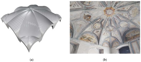
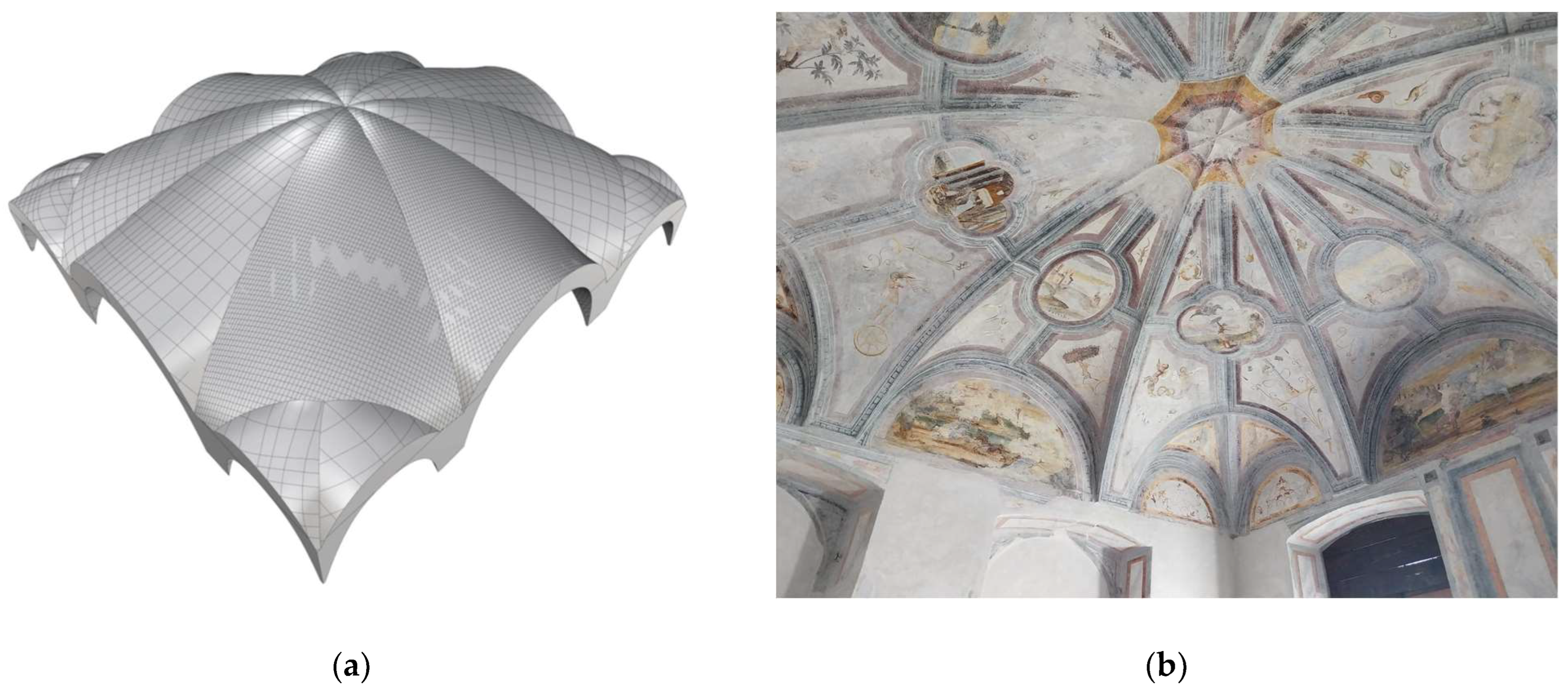
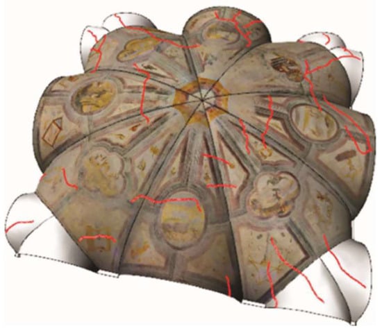
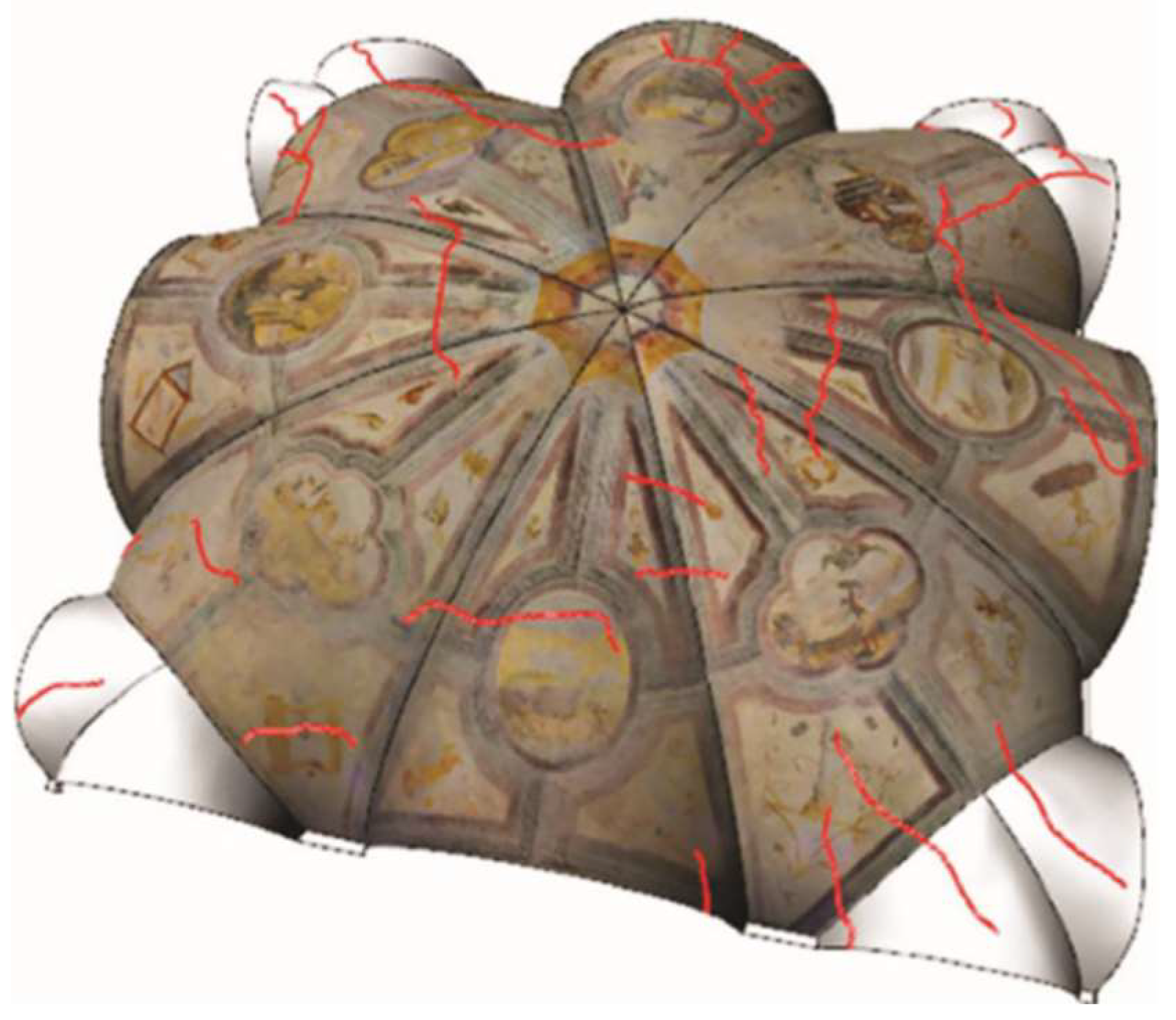
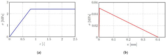
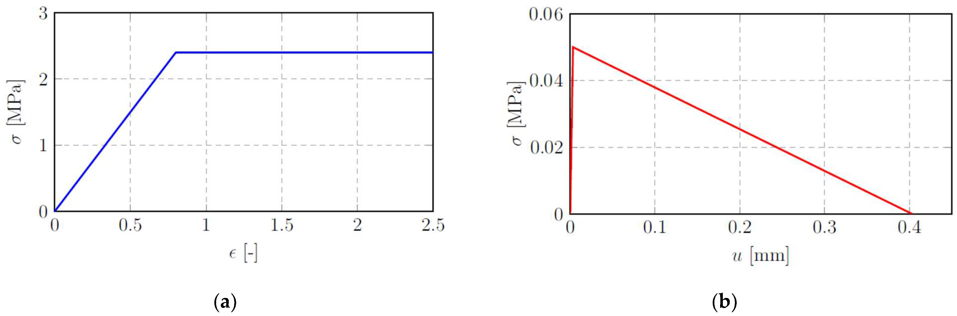
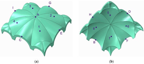
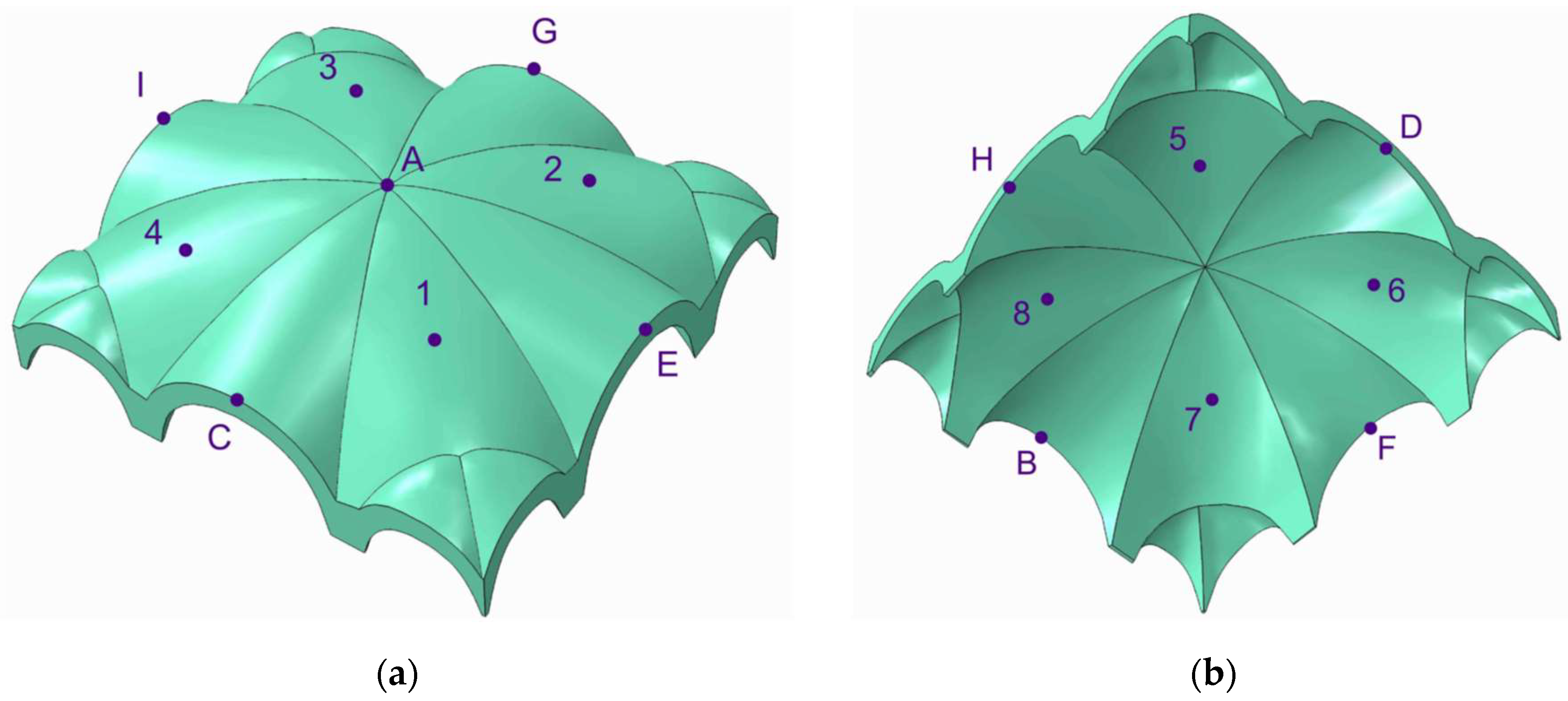
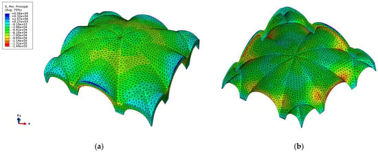
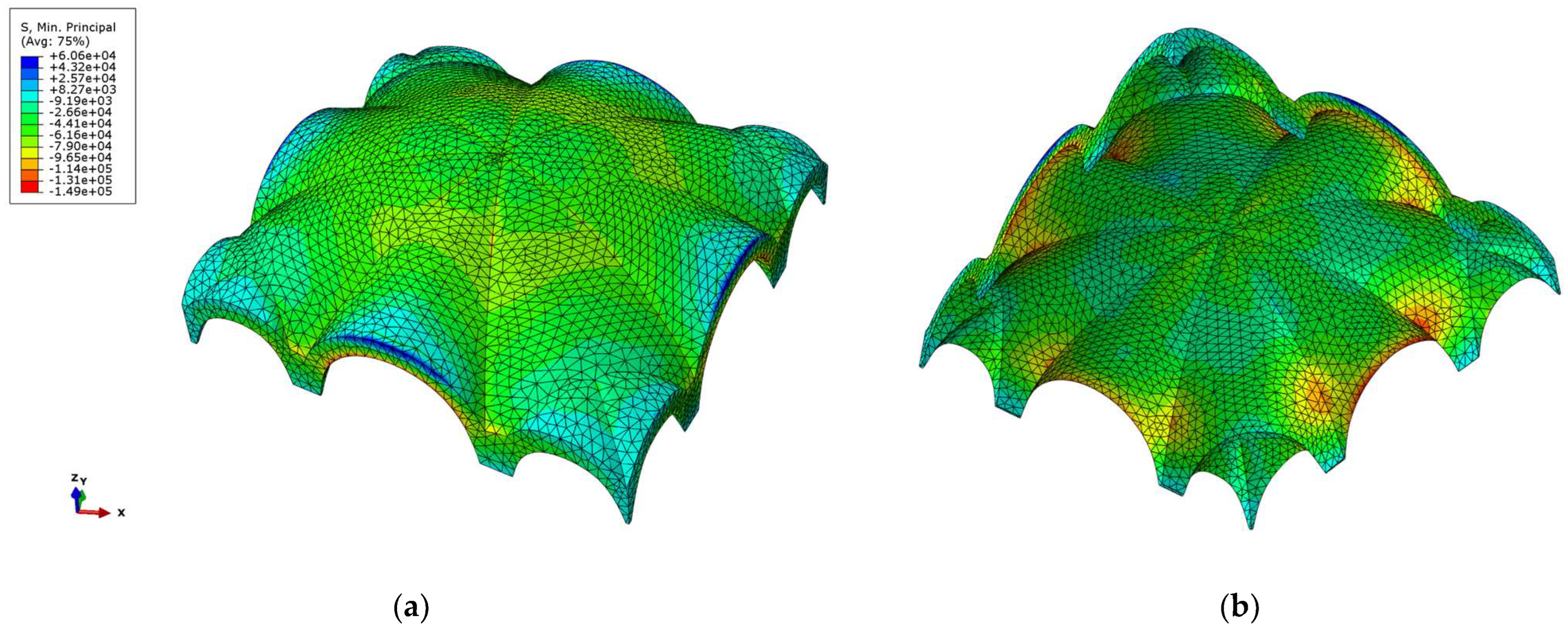
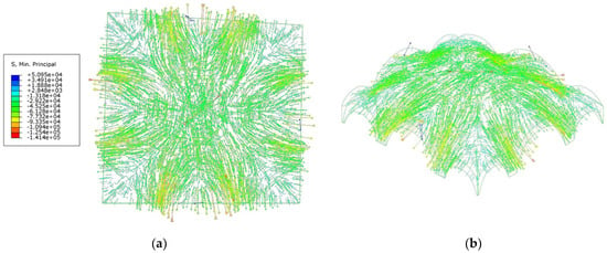
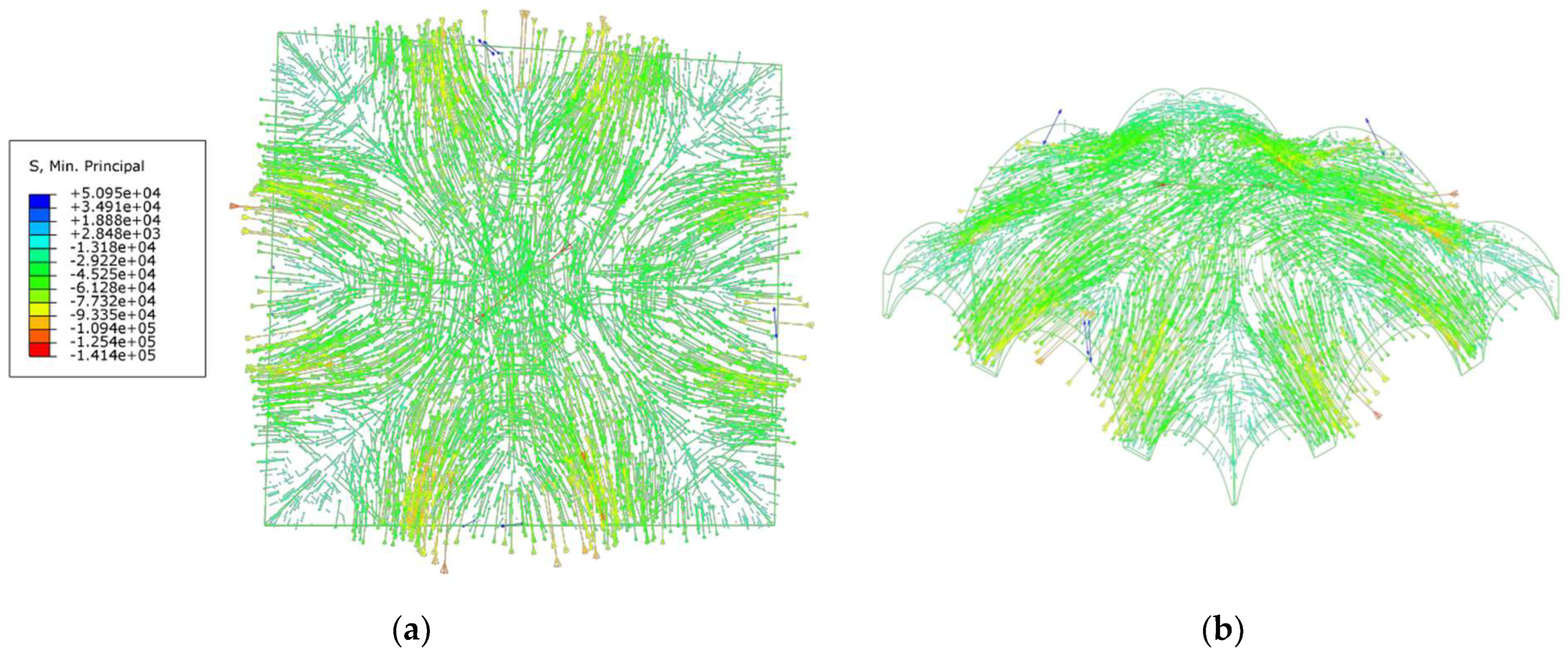
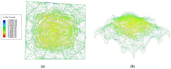
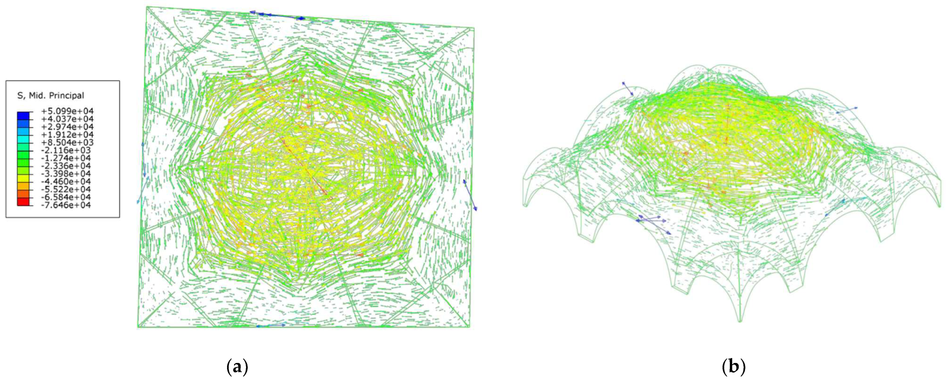
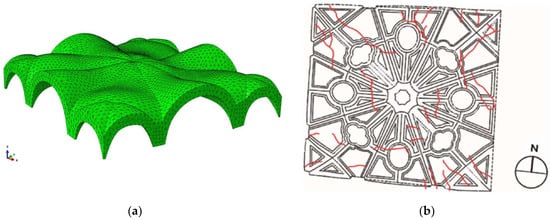
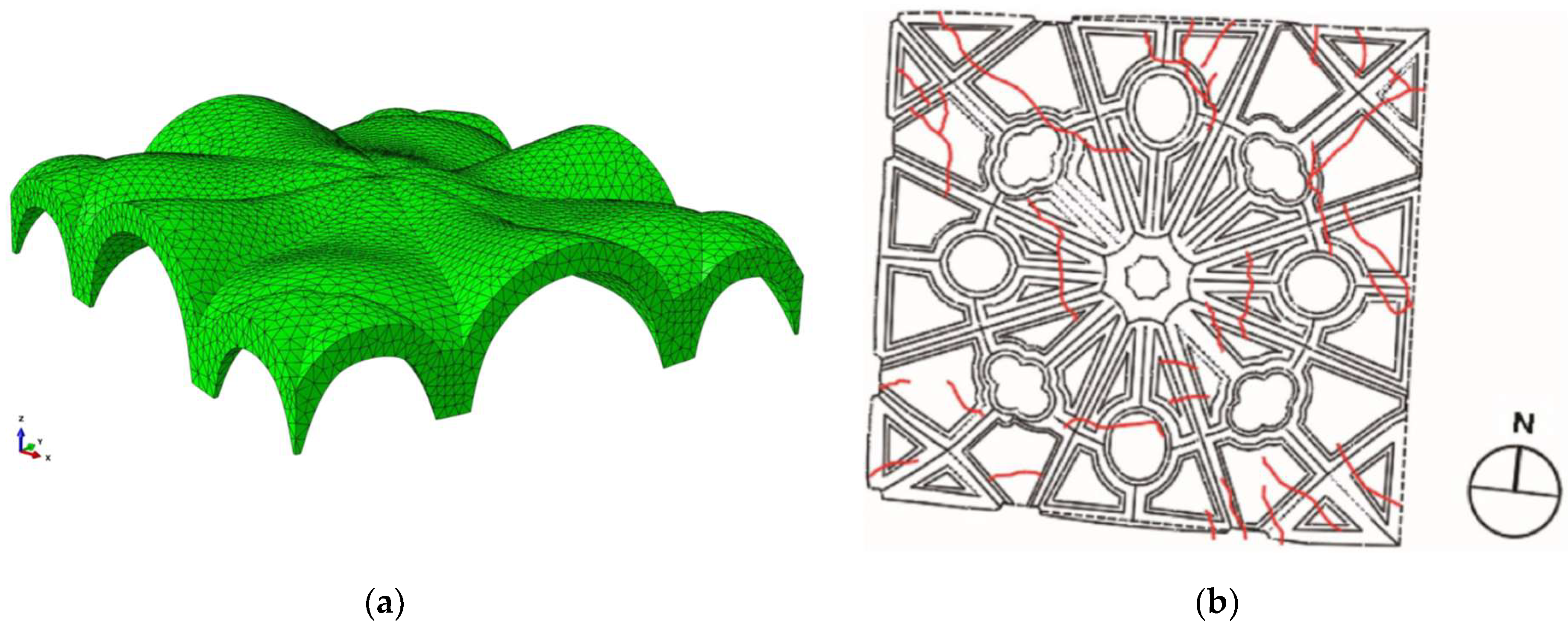
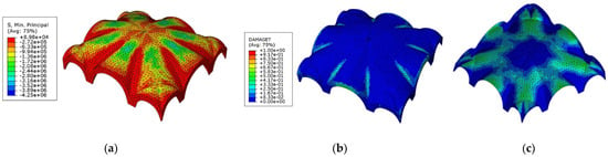
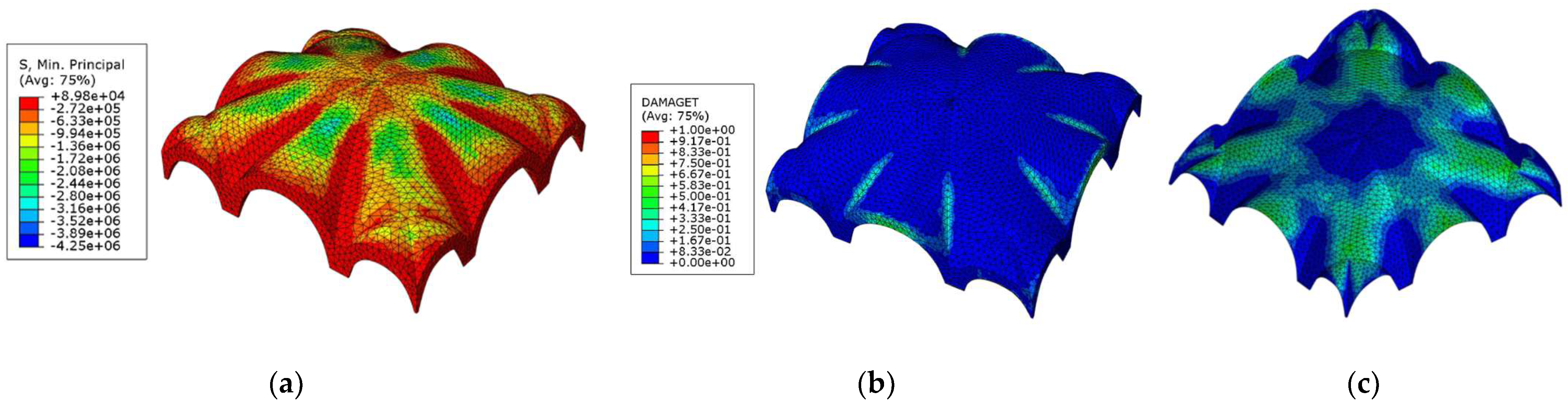
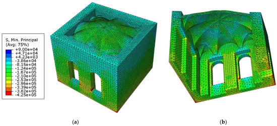
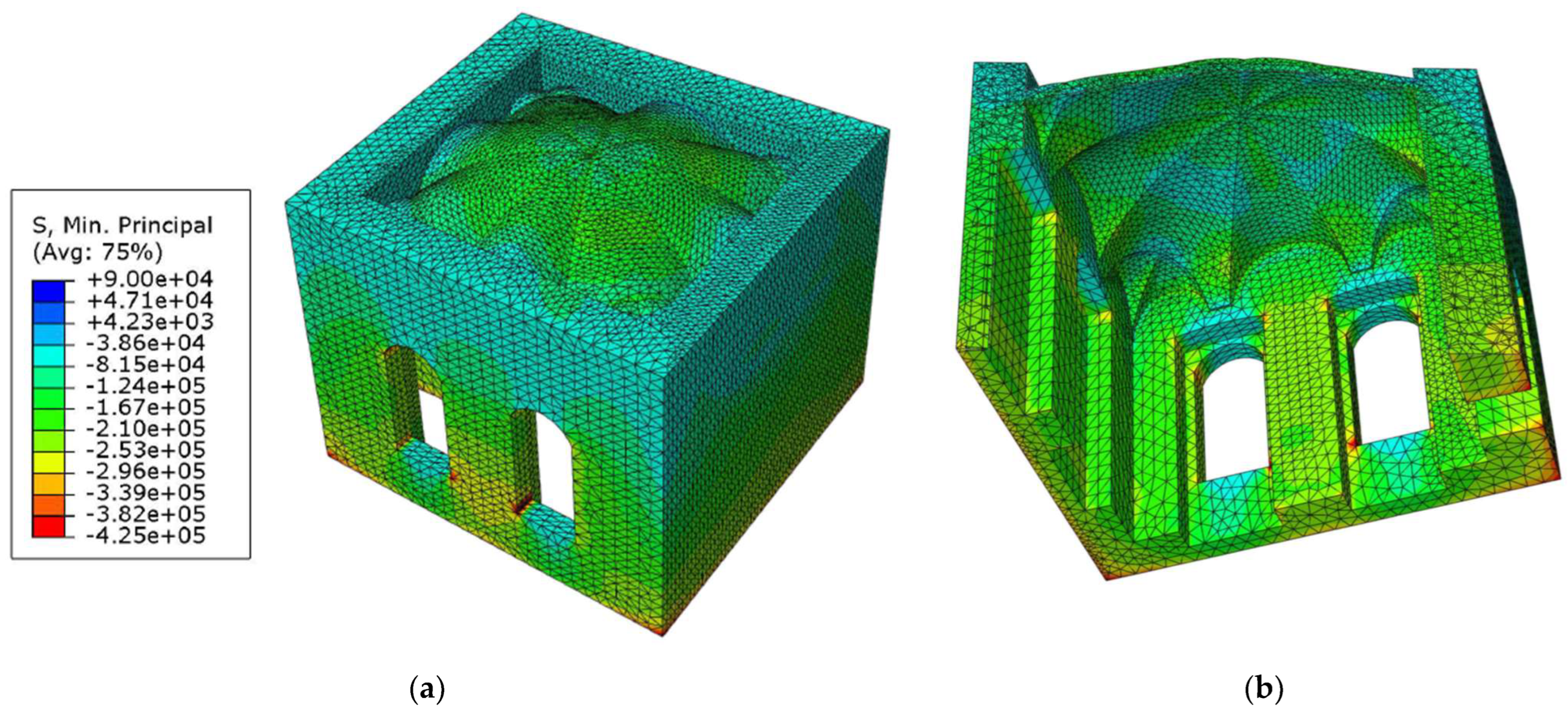
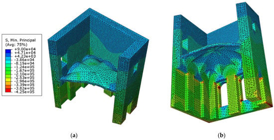
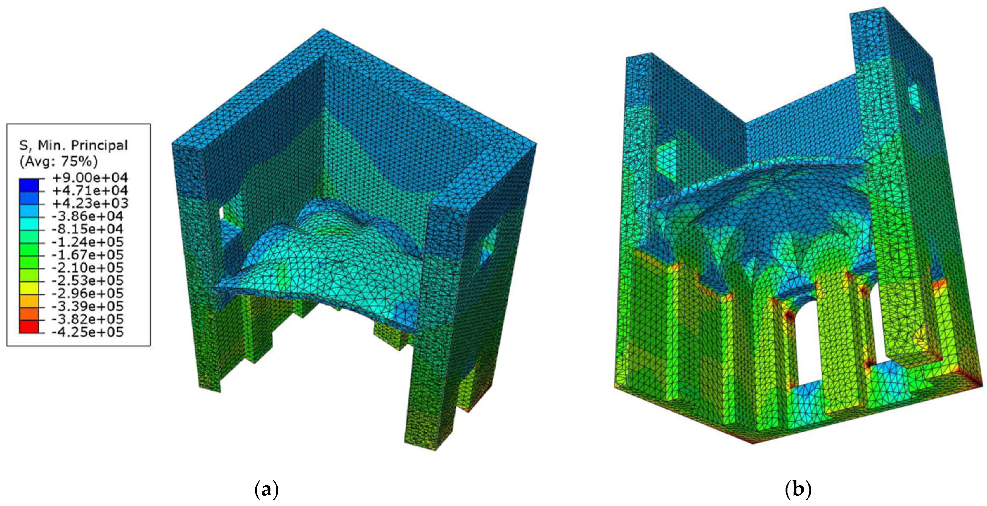
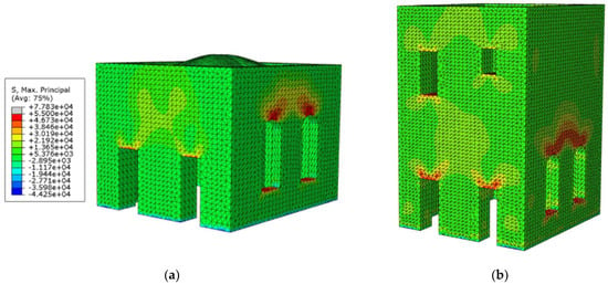
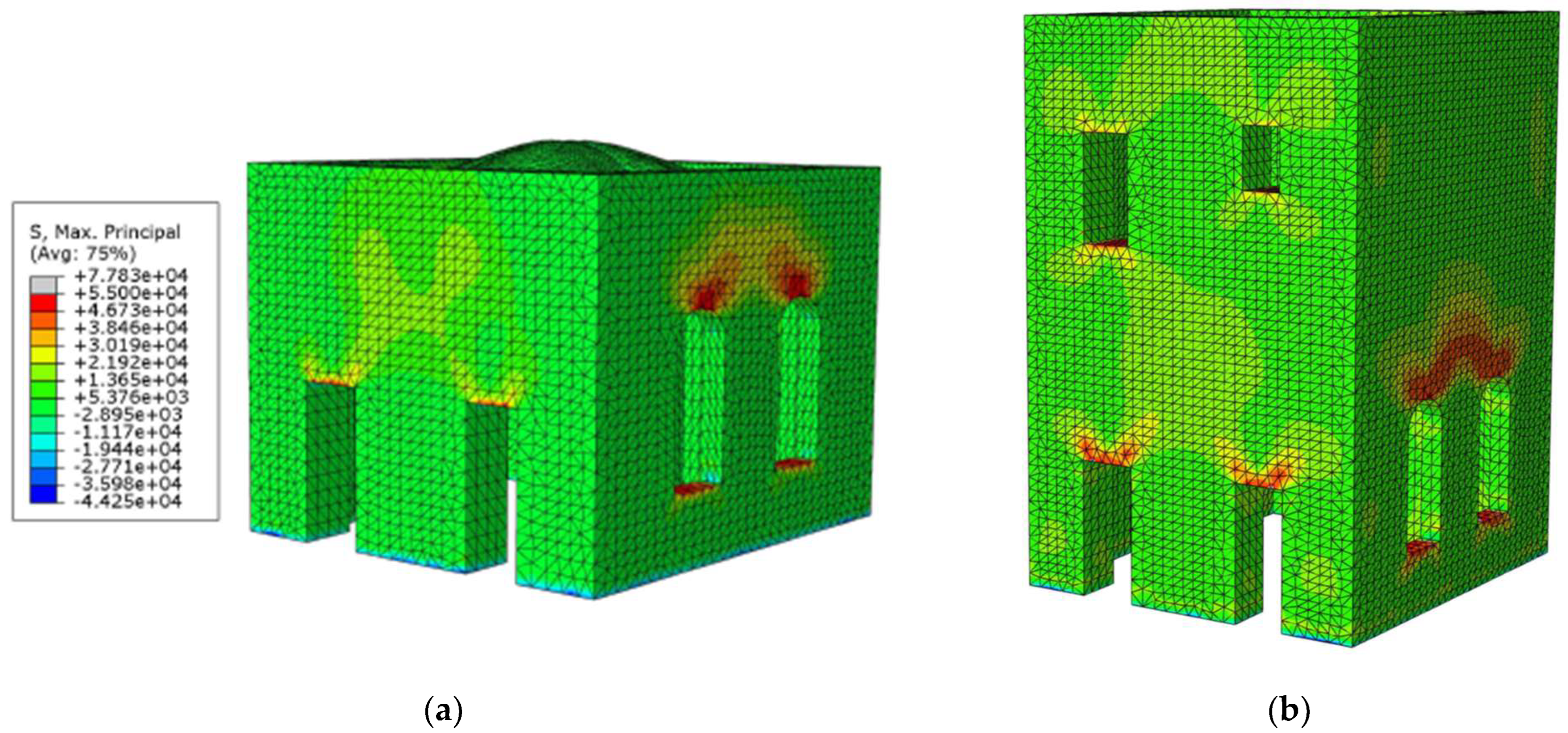
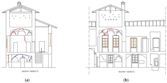
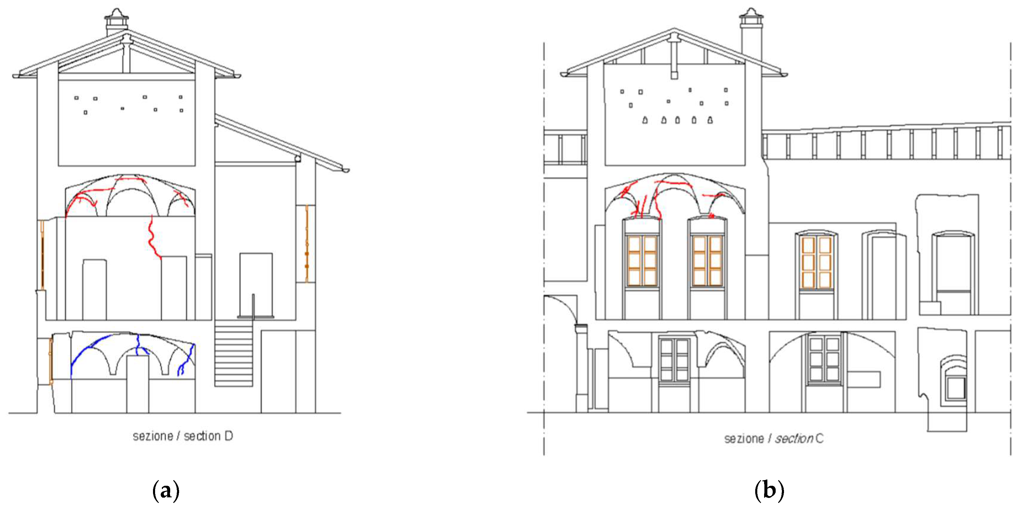
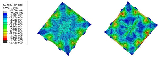
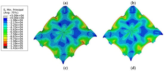
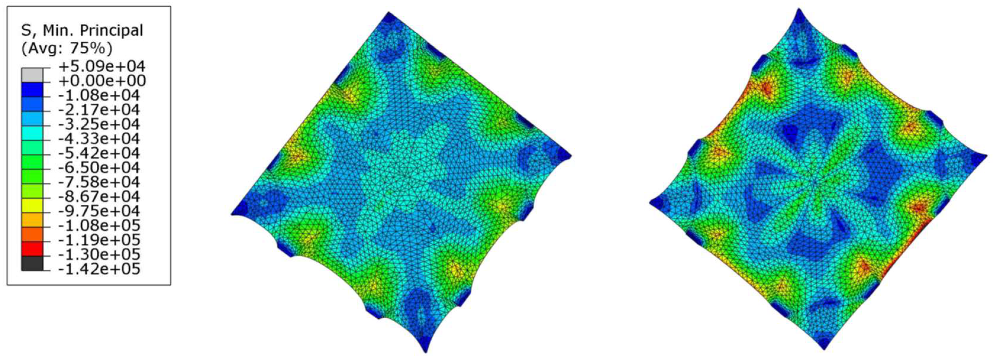
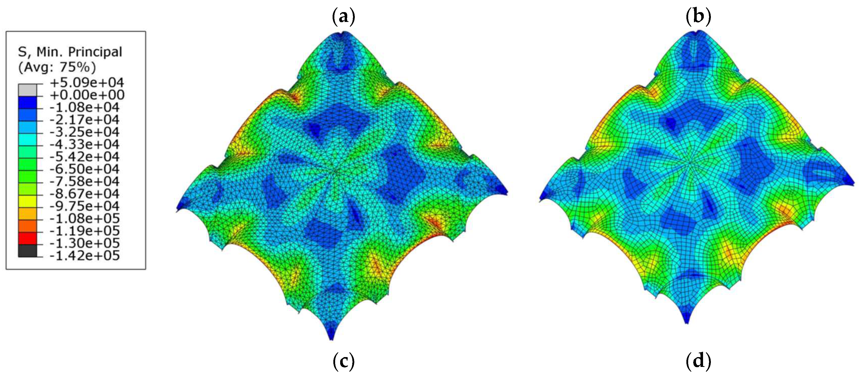
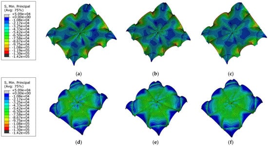
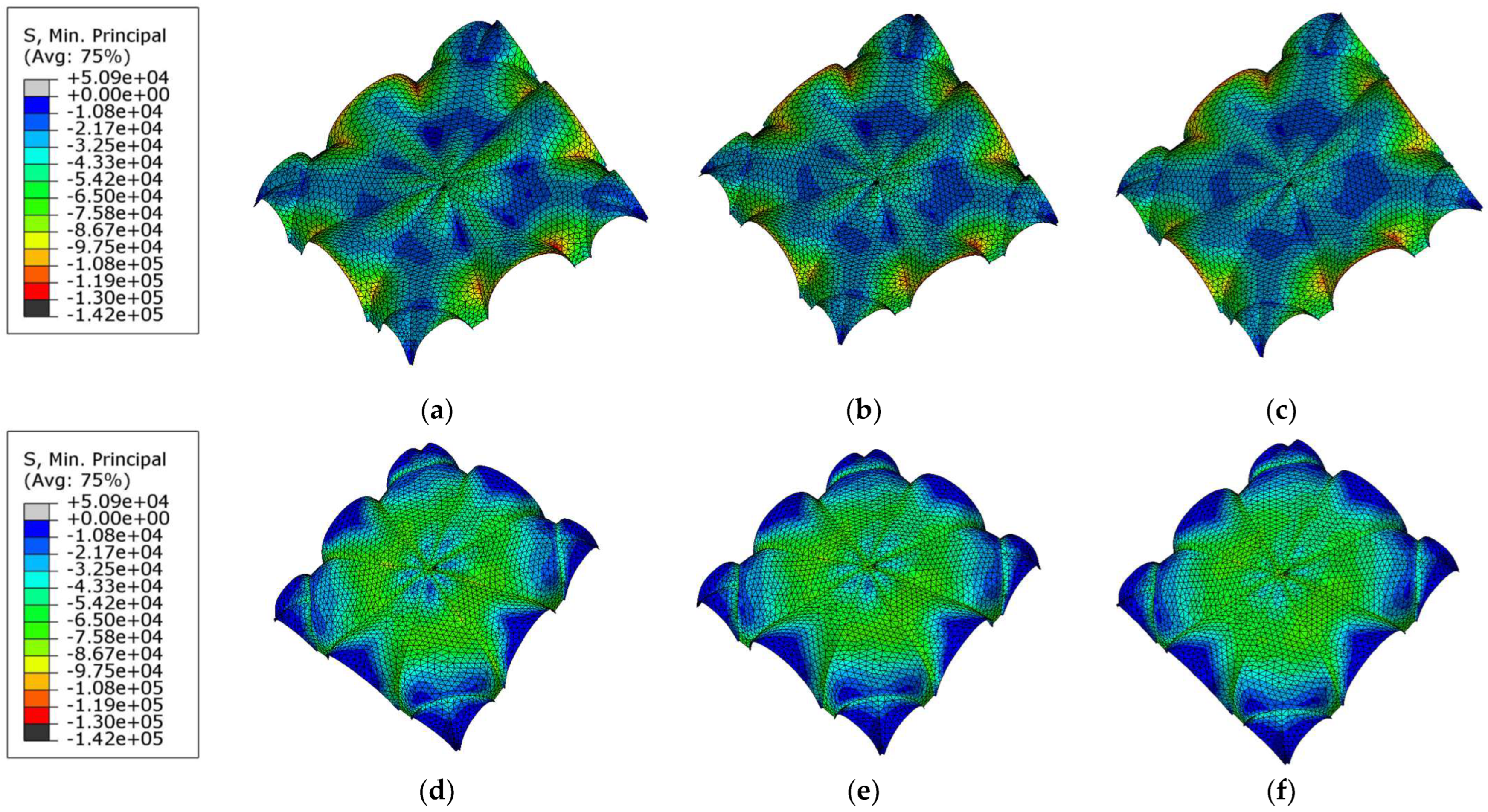
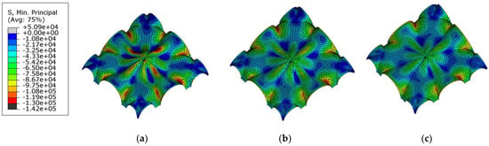
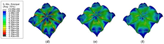
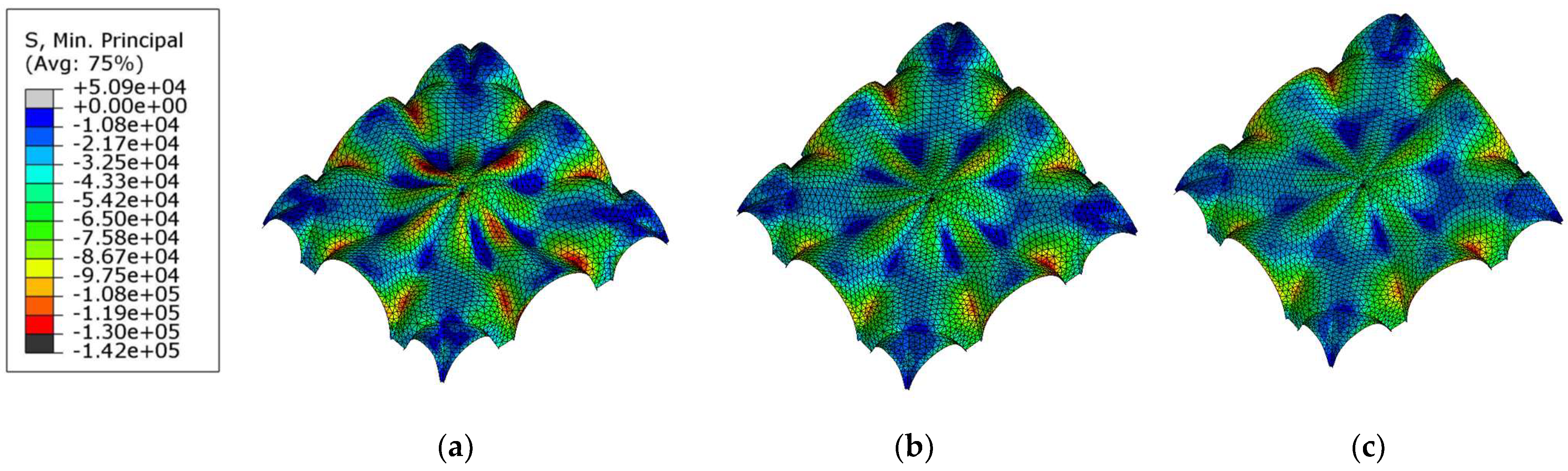
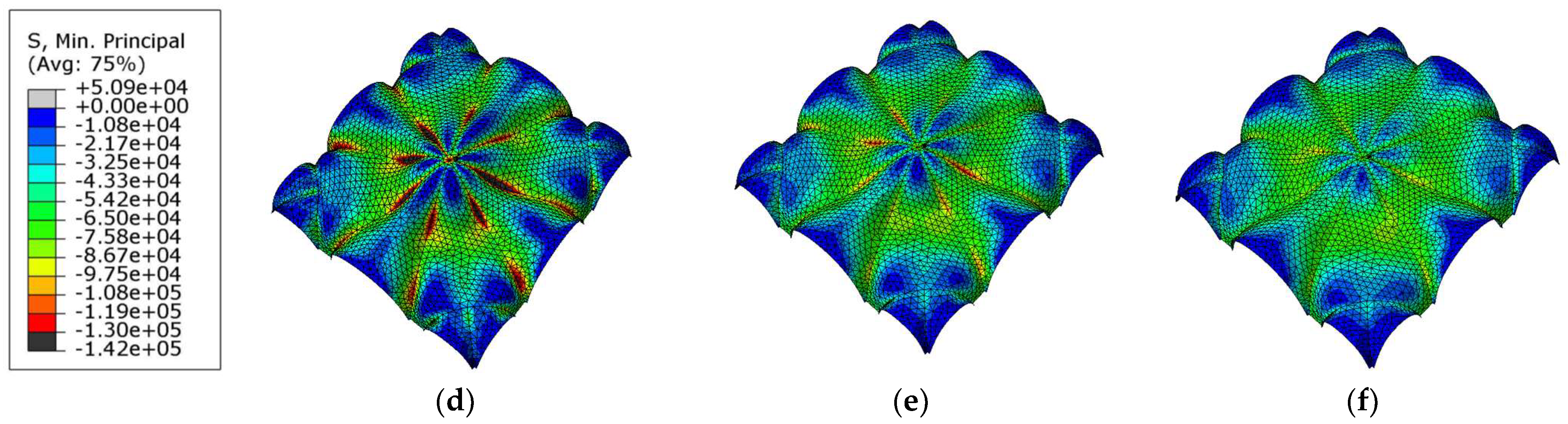



Disclaimer/Publisher’s Note: The statements, opinions and data contained in all publications are solely those of the individual author(s) and contributor(s) and not of MDPI and/or the editor(s). MDPI and/or the editor(s) disclaim responsibility for any injury to people or property resulting from any ideas, methods, instructions or products referred to in the content. |
© 2026 by the authors. Licensee MDPI, Basel, Switzerland. This article is an open access article distributed under the terms and conditions of the Creative Commons Attribution (CC BY) license.