


Abstract
Obstacles can significantly affect the thermal radiation distribution of oil storage tank fires; however, this issue has received relatively limited attention in previous studies. Taking aviation kerosene fires as an example, this study employed a cylindrical flame radiation model combined with the Monte Carlo method to investigate the variation in the radiative flux incident on the target and the flame-target view factor under different obstacle widths (W), heights (H) and target distances (d). The results indicate that obstacles block the flame radiation path, thereby reducing the radiative flux in the region behind the obstacle compared with the unobstructed condition. The view factor first decreases with increasing W and then approaches a stable value. The critical width (Wcr) is independent of H but increases with d. A similar relationship is observed between H and the critical height (Hcr). Based on geometric analysis, analytical expressions for Wcr and Hcr were derived. In addition, a predictive model for the view factor shielding ratio (φ) was established using three dimensionless geometric parameters, achieving a coefficient of determination of R2 = 0.976, which demonstrates good predictive accuracy. These findings provide theoretical guidance for fire risk assessment in tank farm areas.
1. Introduction
Oil storage tanks are critical infrastructure in the petroleum and petrochemical industries, serving essential functions in oil storage and transfer. They play an irreplaceable role in ensuring energy supply and sustaining economic operations. However, the oil is generally flammable. Once a fire occurs, it can not only cause significant economic losses and severe environmental pollution, but also endanger the lives of nearby personnel, leading to major societal consequences. Among the various hazards posed by oil storage tank fires, thermal radiation is the primary cause of equipment damage in tank farms, fire spread and thermal injuries to personnel [1,2]. Therefore, in-depth research on the thermal radiation characteristics is of great significance for improving fire protection design in tank farms and guiding firefighting and rescue operations.
Extensive research has been conducted on the thermal radiation of oil storage tank storage fires, predominantly in the form of pool fire experiments. Regarding the evolution of flame thermal radiation, Robane [3] analyzed the combustion characteristics of liquid acetone and clarified the effects of target distance, height and pool size on heat flux; Kim [4] conducted pool fire experiments to investigate the spatial distribution of radiative flux for methanol, ethanol and acetone fires; Ahmadi [5] employed numerical simulation techniques to investigate the potential for radiative heat flux to trigger domino effects in multi-tank fire scenarios. Elhelw [6] conducted full-scale oil tank fire simulations using the Fire Dynamics Simulator (FDS), characterizing the distribution of radiative heat flux on adjacent tanks under varying wind speeds. To determine the radiative heat flux transferred from a burning tank to its surroundings, Rebec [7] proposed an adequate numerical procedure based on the solid flame radiation model. Building upon this work, Rebec [8] further developed a model for assessing the risk of fire spread between tanks in light fuel oil fires, in which flame radiation was likewise represented through the solid flame model. Recognizing the influence of in-depth radiation absorption on thermal radiation transfer, Alinejad [9] proposed a novel approach for modeling in-depth radiation absorption based on experimental data. The above constitutes part of the research background relevant to the present study; Bathina [10] measured the flame emissivity under dual-pool-fire conditions and explained how it varies with flame height; Deng [11] carried out dual-pool-fire experiments and elucidated the evolution of radiative flux with respect to pool size and fire source spacing.
In terms of flame radiation modeling, the point source model has been widely adopted due to its simplicity and reasonable accuracy in far-field radiation prediction [12]. However, this model exhibits significant errors in the near field. To address this limitation, Shokri and Beyler [13] proposed a cylindrical flame radiation model based on flame geometry; Mudan [14] further developed a tilted cylindrical flame model that accounts for the influence of ambient wind on flame shape; Guelzim [15] further proposed a tilted cylinder view factor that accounts for the target height. For more complex flame configurations, various improved models have also been developed. Pinto [16] analyzed the influence of field-of-view on view factors, considering both cylindrical and conical flame geometries; Ding [17] conducted multiple rectangular pool fire experiments under longitudinal ventilation, revealed the evolution of radiative flux with pool size and wind speed, and proposed a new multi-tilted-cylinder model; Li [18] addressed the dual-fire-source phenomenon under lateral wind and proposed a dual-triangular-prism flame radiation calculation method.
The existing studies have revealed the radiation evolution patterns of pool fires under various boundary conditions and fuel types and have established corresponding flame radiation calculation models for multiple fire scenarios. However, actual oil storage tank farms are not completely open combustion environments. They are typically equipped with fire walls and other protective structures, which can affect combustion characteristics. In recent years, several researchers have begun to examine the influence of obstacles on pool fire behavior. Chen [19] investigated the evolution of pool fire flame morphology under the coupled effects of obstacles and ambient wind, but did not address flame thermal radiation characteristics. Huang [20] conducted wall-adjacent fire experiments, focusing primarily on the influence of heated walls on total incident flux at the target. Although Chen [21,22] studied the effect of obstacles on re-radiation, his experiments were concerned with overhead obstacles and the results were not applicable to oil storage tank fire scenarios. In oil depots, fire walls are commonly installed as opaque structures that can significantly alter the distribution of thermal radiation. Existing research has not adequately revealed the influence of these obstacles on incident radiative flux at target locations. Therefore, from a theoretical perspective, this work systematically investigates the effects of obstacle width, height and the distance between the target and the obstacle on the view factor and radiative flux based on the cylindrical flame model assumption. The findings are expected to provide a theoretical reference for fire risk assessment in oil storage tank farms.
2. Methods
2.1. Radiation Model for Pool Fire Flames
Flame height is defined as the vertical distance from the flame base to the visible flame tip. It determines the size of the radiating surface and serves as a key parameter in flame radiation models. For turbulent buoyant flames, Thomas [23] proposed a classical flame height correlation based on the fire source diameter, burning rate, and ambient density:
where is the fuel mass loss rate, calculated by Equation (2) [24], ρa is the ambient air density, g is the gravitational acceleration constant, and D is the fire source diameter.
In this equation, is the fuel mass loss rate at infinite pool diameter, is the extinction coefficient, β is the mean beam length corrector. In engineering applications, and β can be treated as constants but their values depend on the fuel type. Based on the fuel mass loss rate , the fire source diameter D, and the effective heat of combustion of the fuel , the total heat release rate is:
Flames from hydrocarbon fuel combustion contain high-temperature gaseous products and soot particles. A portion of the energy released by combustion is transferred to the surroundings as thermal radiation. The ratio of the radiative heat release rate to the total heat release rate is defined as the radiative fraction , which is calculated as shown in Equation (4) [13].
Two classical approaches have been proposed for calculating flame radiation: the point source model and the solid flame model. The point source model simplifies the flame as a single radiating point located at the flame center. Although straightforward, studies have shown that it yields significant errors in the near-field region within 2.5 pool diameters from the fire source. In contrast, the solid flame model treats the flame as a thermal radiation source with a defined geometry, providing reliable predictions for both near-field and far-field radiation [13]. Consequently, this model has been more widely adopted. Using the solid flame model approach, Shokri and Beyler [13] simplified the flame shape as a cylinder. The incident radiative flux at a target can be calculated by Equation (5) [13]. Here, Ef is the surface emissive power of the flame, and F12 is the view factor between the external target and the flame. For the cylindrical model, Ef can be obtained from Equation (6).
Let L denote the horizontal distance from the target to the center of the cylinder base. When the target surface normal faces the flame, Mudan [25] provided the analytical expression for the view factor F12 as follows:
where A, S and h are defined as:
2.2. Calculation Method for Obstructed View Factor
Although Equation (7) provides an analytical solution for the view factor between a cylindrical flame and a target, it is only applicable under unobstructed conditions. When obstacles exist between the flame and the target, some radiation paths are blocked, causing Equation (7) to overestimate the radiative flux. The solid flame model assumes a uniform distribution of the surface emissive power Ef; that is, for given fire source conditions, Ef remains constant. According to Equation (6), the incident radiative flux on the target therefore depends solely on the view factor F12. Let the view factor between the flame and the target under obstructed conditions be denoted as , then the incident radiative flux is determined by . The obstructed view factor depends on multiple parameters including the obstacle geometry and the target location, making it difficult to derive a closed-form analytical expression. Therefore, the Monte Carlo (MC) method is employed in this study to compute the view factor under obstructed conditions. The MC method is a statistical approach that simulates radiation transfer by uniformly emitting a total of N energy bundles from various positions on emitting surface 1. The fraction of bundles intercepted by surface 2 represents the view factor for the given geometric configuration [26]. Accordingly, is given by Equation (9). In this work, rays are sampled within the hemisphere facing the flame using a cosine-weighted, Lambertian angular distribution. Each ray is then analytically tested for intersection with the finite cylindrical flame and the intervening wall. If the wall intersection occurs before the flame intersection and lies within the wall boundaries, the ray is classified as blocked; otherwise, a ray reaching the flame is classified as visible. The simulations are implemented in Python 3.12.0 using NumPy for random sampling and vectorized ray–geometry calculations.
3. Case Study of the Effect of Obstacles on Flame Radiation
Hazard analysis of storage tank fires is a critical component of risk assessment for chemical plants and fuel depots. The thermal radiation intensity from flames to surrounding targets serves as the key basis for determining safe separation distances. For example, according to the Chinese national standard GB/T 37243-2019, “Determination method of external safety distance for hazardous chemicals production units and storage installations [27]”, when the incident radiative flux reaches 12.5 kW/m2, exposed personnel may suffer burn injuries and may even face a risk of fatality if the exposure duration exceeds 1 min. This radiation level can also cause melting and deformation of plastic equipment components, thereby impairing normal equipment function. In actual fuel depots, storage tanks are typically surrounded by noncombustible structures such as fire walls. These structures are opaque to flame radiation and partially block the radiation paths from the flame, resulting in lower incident radiative flux on the target compared to unobstructed conditions. Neglecting the shielding effect of obstacles in radiation hazard analysis therefore leads to overly conservative results, which is unfavorable for the rational determination of safe separation distances. To quantitatively investigate the shielding effect of obstacles on flame radiation and its influence on the incident radiation flux, this study analyzes a fire scenario involving an RP-3 aviation kerosene storage tank with a diameter D = 12 m. Since the fuel is aviation kerosene, the mass burning rate and the extinction-absorption coefficient product ·β are taken as 0.054 kg/(m2·s) and 1.6 m−1 [28], and the heat of combustion = 42.8 MJ/kg [29]. Based on these values, the flame height is determined using Equation (1) as Hf = 17.8 m, and the surface emissive power is calculated from Equation (6) as Ef = 56.7 kW/m2.
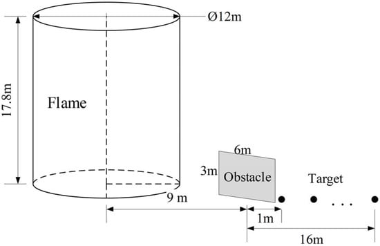
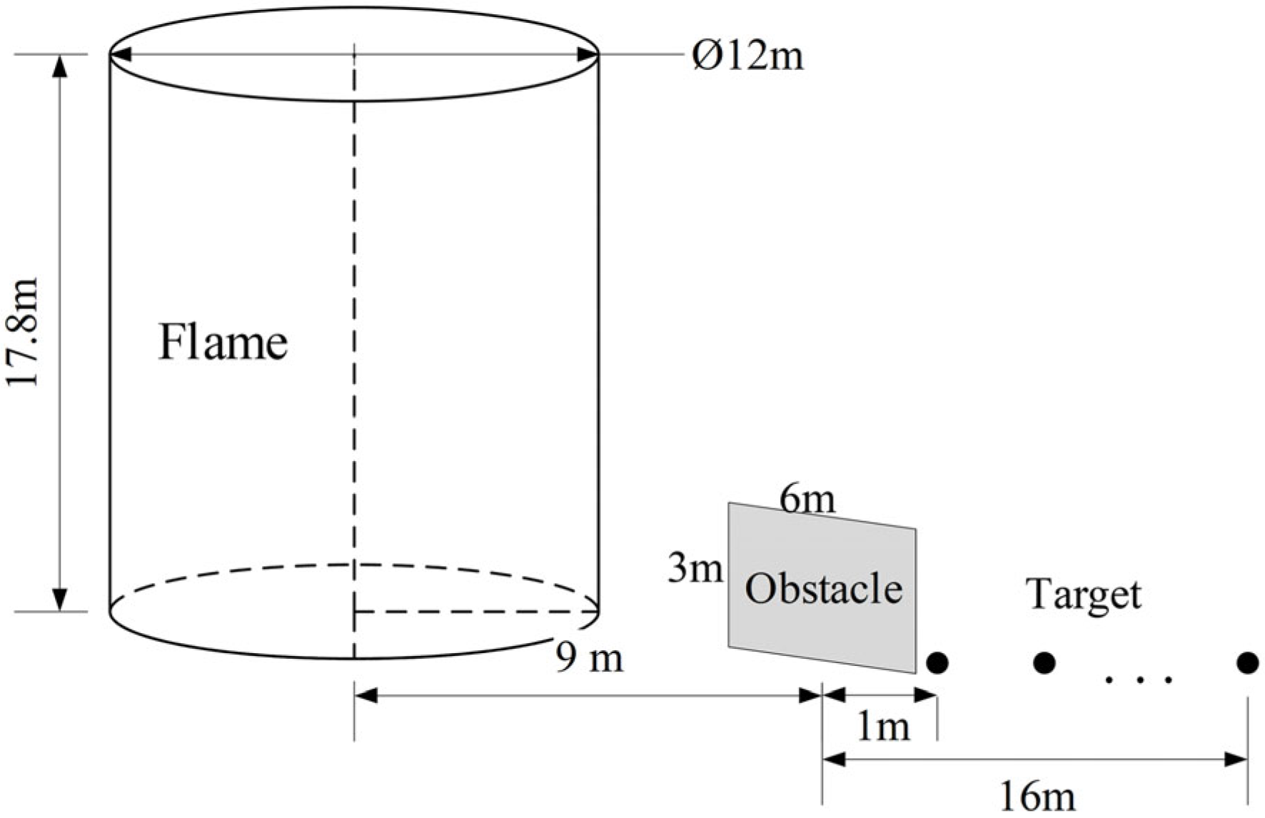
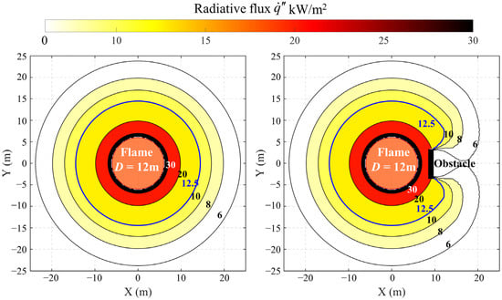
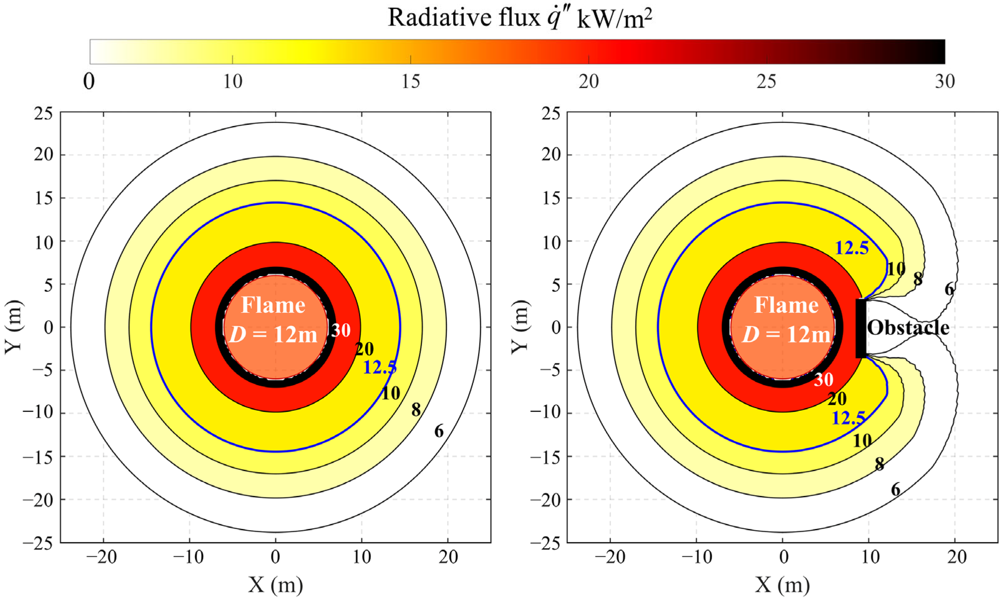
A schematic of the case study scenario is shown in Figure 1. An obstacle measuring 6 m (width) by 3 m (height) is assumed to be placed 9 m from the center of the fire source base. The radiative flux distribution in the unobstructed scenario is calculated using Equations (5) and (7), while the distribution in the obstructed scenario is computed using Equation (5) and the MC method. The results are presented in Figure 2. In the unobstructed scenario, the radiative flux contours exhibit a concentric circular pattern due to the axisymmetric geometry of the cylindrical flame, with values decreasing progressively with increasing distance from the fire center. However, in the obstructed scenario, the contour lines near the obstacle become distorted and lose their circular symmetry, indicating that the obstacle modifies the local radiation field.
Figure 1.
Schematic diagram of the case study scenario.
Figure 2.
Flame radiative flux distribution under unobstructed and obstructed conditions.
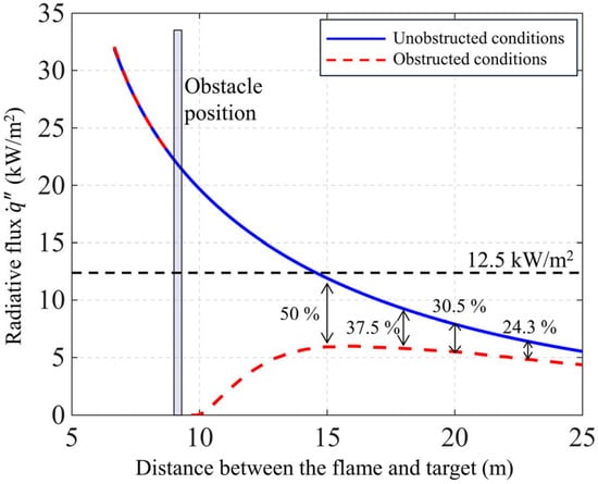
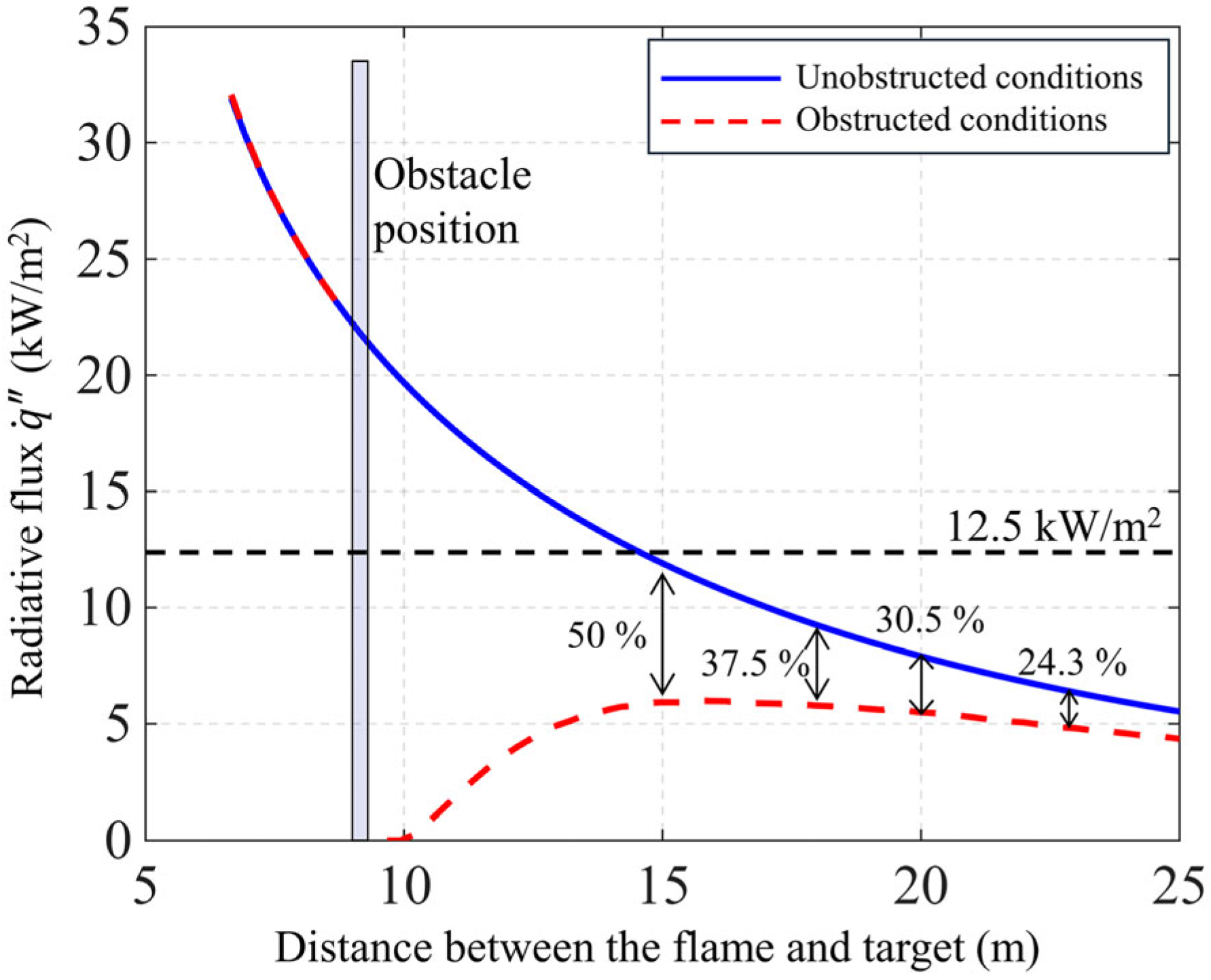
To further illustrate the attenuation effect of the obstacle, radiative flux values were extracted at target positions spaced 1 m apart behind the obstacle. The variation in radiative flux with distance from the fire center is plotted for both scenarios in Figure 3 The obstacle substantially reduces the radiative flux received by targets in its shadow. Specifically, compared to the unobstructed scenario, the radiative flux in the obstructed scenario is reduced by approximately 50%, 37.5%, 30.5% and 24.3% at target distances of 15 m, 18 m, 20 m and 23 m, respectively. This indicates that the attenuation effect is more pronounced for targets closer to the obstacle. At 10 m, the obstacle completely blocks the flame radiation, reducing the incident flux to zero. Figure 3 also marks the radiative flux level of = 12.5 kW/m2. In the unobstructed scenario, the radiative flux exceeds this risk threshold for targets between approximately 9 m and 14 m from the fire center, posing risks of equipment damage and personnel injury. However, in the obstructed scenario, the radiative flux within this 9 m to 14 m range falls below 12.5 kW/m2. In summary, obstacles exert a significant influence on the spatial distribution of flame radiative flux and effectively reduce radiation levels in the shielded region. Neglecting the obstacle shielding effect in fire risk assessment would overestimate the target radiative flux, yielding overly conservative safety distance estimates that hinder accurate risk evaluation and rational safety design. It should be noted that Figure 3 is intended only as a simple illustrative example to demonstrate the influence of the obstacle on the radiative flux distribution. The corresponding results are specific to the selected configuration and should not be interpreted as a universal design rule.
Figure 3.
Variation in radiative flux under unobstructed and obstructed conditions.
4. Evolution Rule of the Obstructed View Factors
4.1. Configuration of Analysis Conditions
Within the computational framework of the solid flame radiation model, the difference in radiant heat flux received by a target under obstructed and unobstructed conditions is solely attributable to the change in view factor. Accordingly, the shielding effect of an obstacle on flame radiation can be characterized by examining how the obstructed view factor varies with geometric parameters. This study considers a tank fire scenario involving aviation kerosene with a tank diameter of D = 12 m. The obstacle is positioned 9 m from the center of the fire source. To systematically investigate the influence of obstacle geometry on the view factor, rectangular obstacles with varying widths W and heights H are examined. In addition, six separation distances d between the target and obstacle are specified to evaluate how radiative flux varies at different target locations. The complete set of 864 simulation conditions is summarized in Table 1.
Table 1.
Summary of analysis conditions.
4.2. Analysis of Obstructed View Factor Results
4.2.1. Sensitivity Analysis of Monte Carlo Ray Count
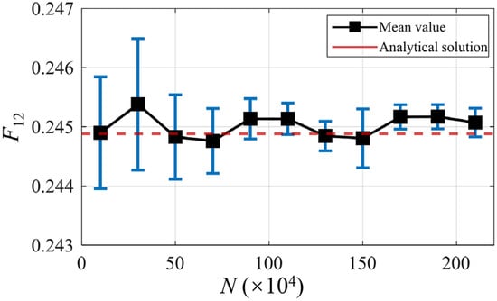
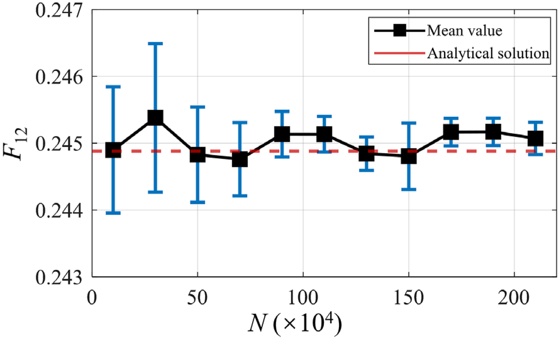
As a statistical sampling-based numerical method, the Monte Carlo (MC) approach produces view factor results that depend on the number of simulated rays, NNN. An excessively large N substantially increases computational cost, whereas an excessively small N introduces considerable statistical uncertainty. Therefore, before examining the behavior of , a sensitivity analysis of N was conducted to balance computational accuracy and efficiency. Since the unobstructed view factor F12 has an analytical solution, it was used as a benchmark to validate the MC results. Figure 4 shows the variation in F12 with N under unobstructed conditions at L = 12 m. For each value of N, the MC simulation was repeated six times, and the standard deviation of the six runs is also presented. The results show that when N exceeds 1.5 × 10⁶, the computed view factor becomes stable and the standard deviation decreases significantly, indicating good reproducibility. Considering both accuracy and computational efficiency, N = 1.5 × 10⁶ was adopted in all subsequent analyses.
Figure 4.
Variation in the calculated F12 with the number of rays.
4.2.2. Variation in the Obstructed View Factor
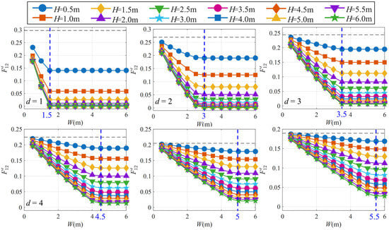
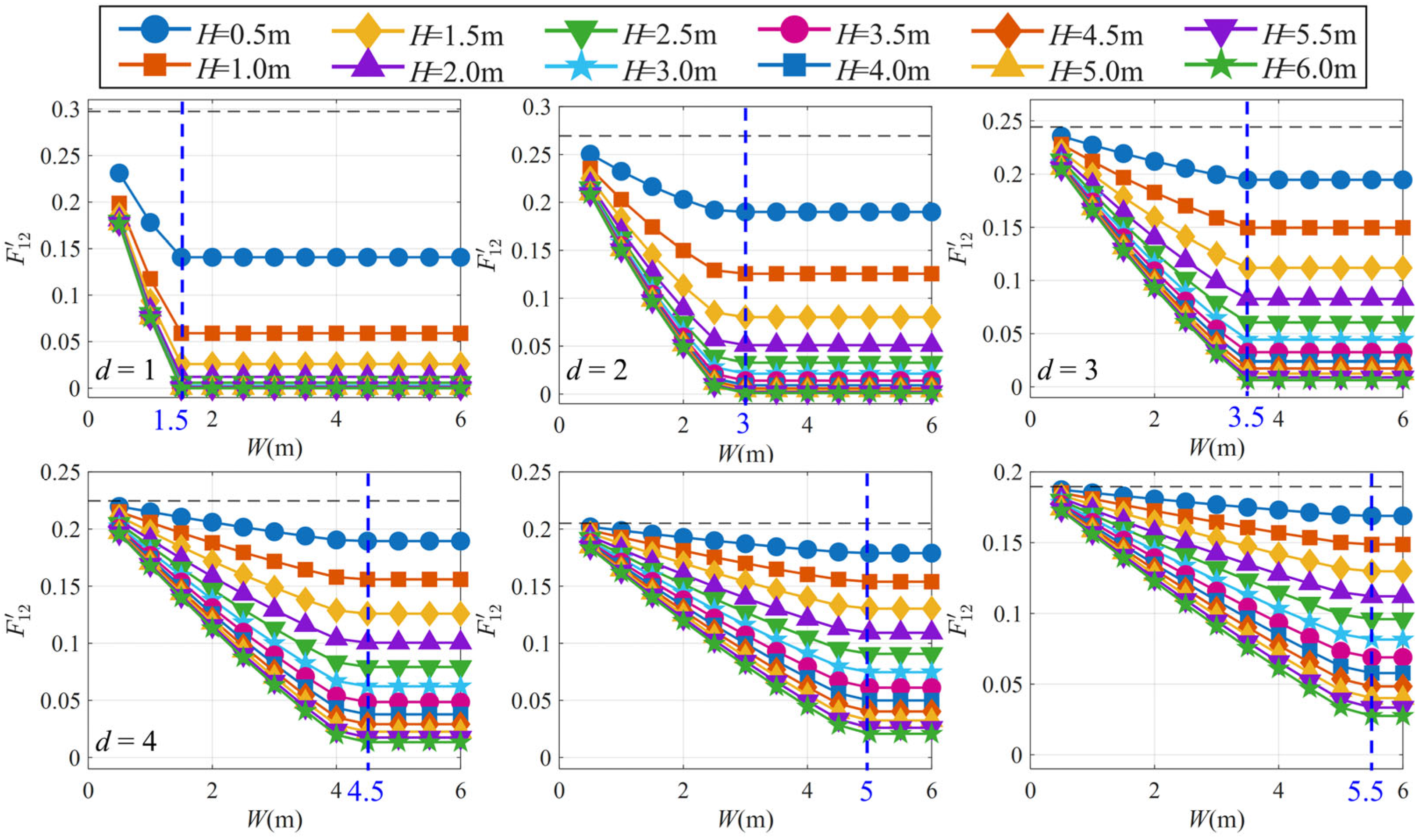
Figure 5 shows the variation in the obstructed view factor across all cases, with the dashed line representing the unobstructed view factor F12. At a given d and H, does not decrease monotonically with increasing obstacle width W; instead, it exhibits a piecewise trend. When W is small, decreases monotonically as W increases. However, once W exceeds a critical width, Wcr, gradually stabilizes and becomes insensitive to further increases in W. The blue dashed lines in the figure indicate the corresponding Wcr values for each d. Notably, Wcr is independent of H but increases linearly with d. The decrease in when W < Wcr can be attributed to the fact that a wider obstacle blocks more radiation paths from the flame to the target, thereby reducing the view factor. The existence of Wcr can be explained by the geometric relationship between the target and the cylindrical flame.
Figure 5.
The obstructed view factor.
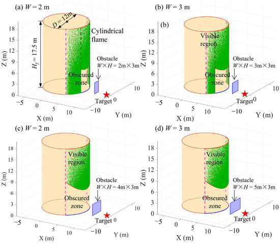
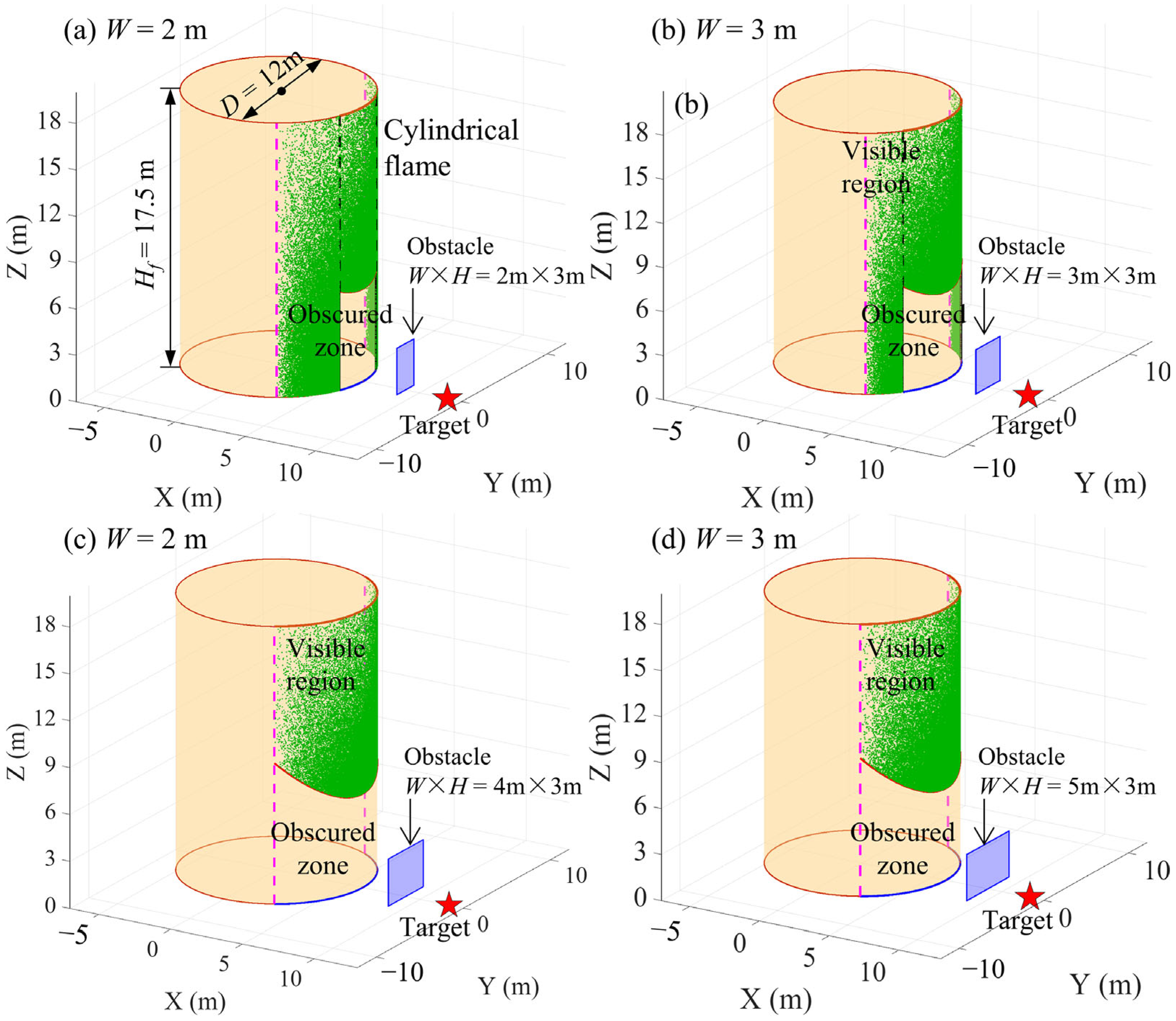
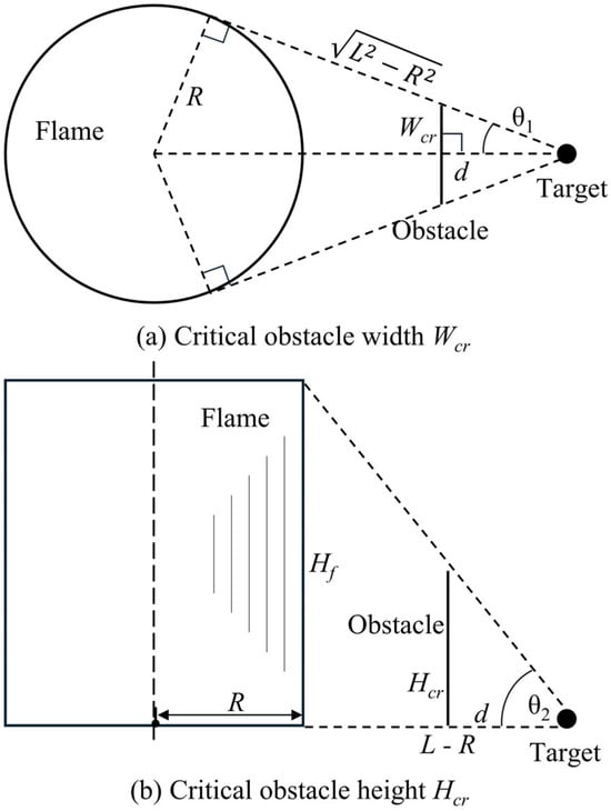
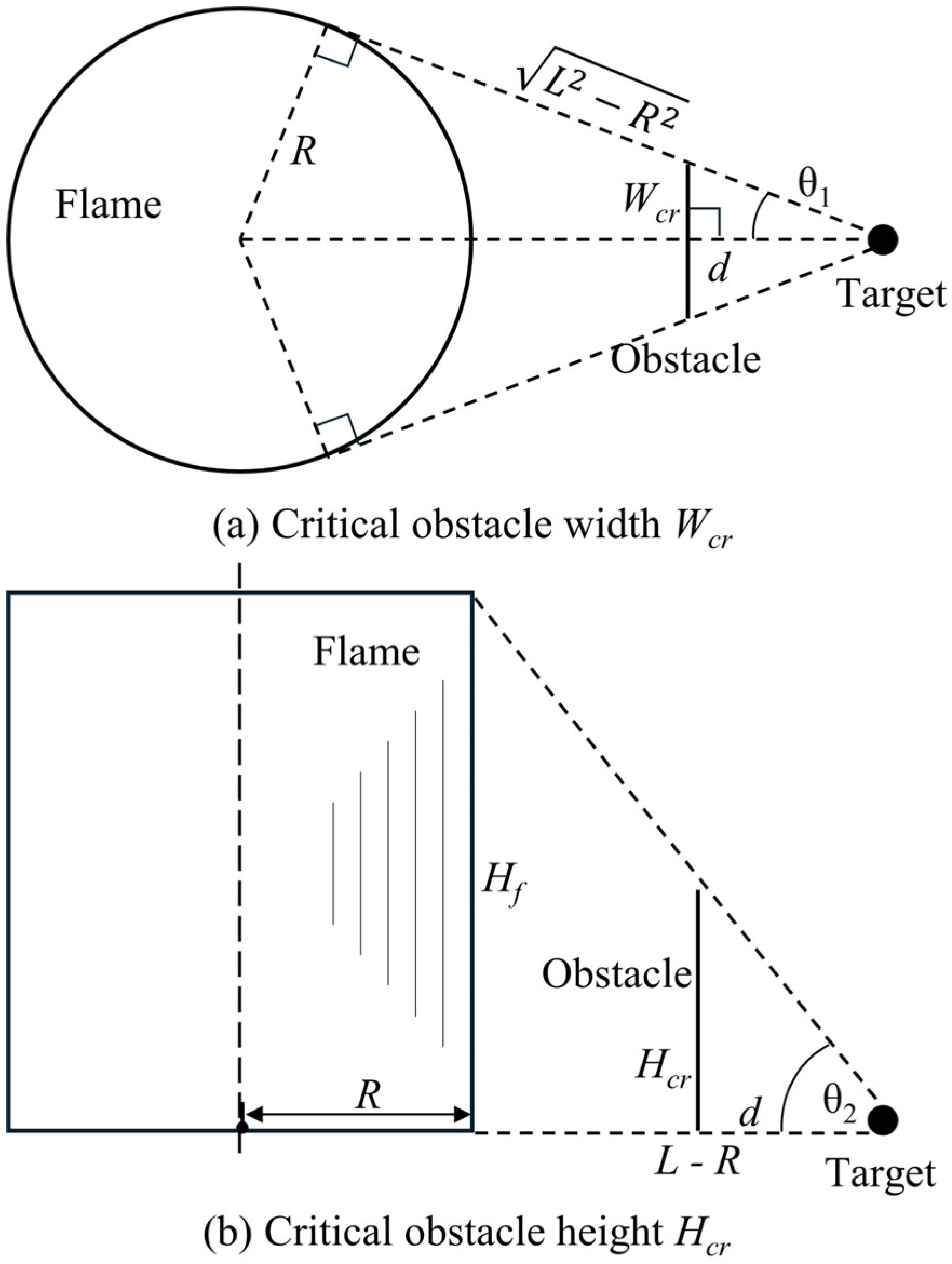
To further elucidate the physical mechanism underlying the variation of with W, Figure 6 shows the visible region of the cylindrical flame surface from the target at d = 3 m and H = 3 m for W = 2, 3, 4 and 5 m. The green dots represent the intersection points between the MC-emitted rays and the cylindrical surface, and their distribution outlines the visible region of the flame. The pink dashed lines indicate the visible boundary under unobstructed conditions. It can be seen that the obstacle creates an obscured zone within the otherwise visible region of the flame surface, and the extent of this zone does not vary monotonically with increasing W. When W = 2 m, the boundary of the obscured zone lies within the visible boundary, as shown in Figure 6a. At W = 3 m, the obscured zone expands, but its boundary still remains within the visible limit. When W = 4 m, the boundary of the obscured zone coincides with the visible boundary, indicating that the shielding effect has fully covered the circumferential range of the flame visible to the target. Therefore, any further increase in W can no longer enlarge the obscured zone. At W = 5 m, the obscured zone remains identical to that at W = 4 m. These results demonstrate that once W reaches the critical width, Wcr, the shielding boundary covers the entire circumferential viewing range of the cylindrical flame from the target. Further increases in obstacle width therefore provide no additional shielding, which explains the plateau of beyond Wcr in Figure 5. Similarly, a critical height, Hcr, exists in the vertical direction. Once the obstacle height exceeds Hcr, the shielding boundary in the vertical direction covers the full visible extent of the flame and further increases in H no longer affect the obstructed view factor. Due to the curvature of the cylindrical surface, this upper boundary appears, in front view, as a curve symmetric about the central axis, with its minimum Z-coordinate located at the generatrix facing the target. At H = Hcr, this minimum Z-coordinate coincides with the flame height Hf. The geometric schematics used to determine Wcr and Hcr are shown in Figure 7. As illustrated in Figure 7a, in top view, the visible arc of the flame is defined by the region enclosed by the two tangent lines drawn from the target to the circular cross-section. The tangent length is , and Wcr is given by the intercept of these two tangent lines on the obstacle plane. Accordingly, Equation (10) can be derived from the geometric relationship between θ1 and d. As illustrated in Figure 7b, in side view, the line extending from the target over the top edge of the obstacle to the nearest generatrix must pass through the flame tip Hf. Because the horizontal distance between the target and this generatrix is L − R, Equation (11) can be obtained from the geometric relationship between θ2 and d.
Figure 6.
Schematic diagram of the visible flame region under typical conditions.
Figure 7.
Geometric determination of critical obstacle width and height.
4.2.3. Characterization Equation for the View Factor Shielding Ratio
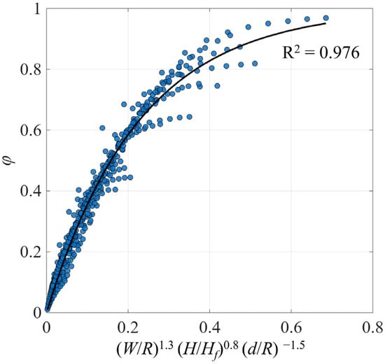
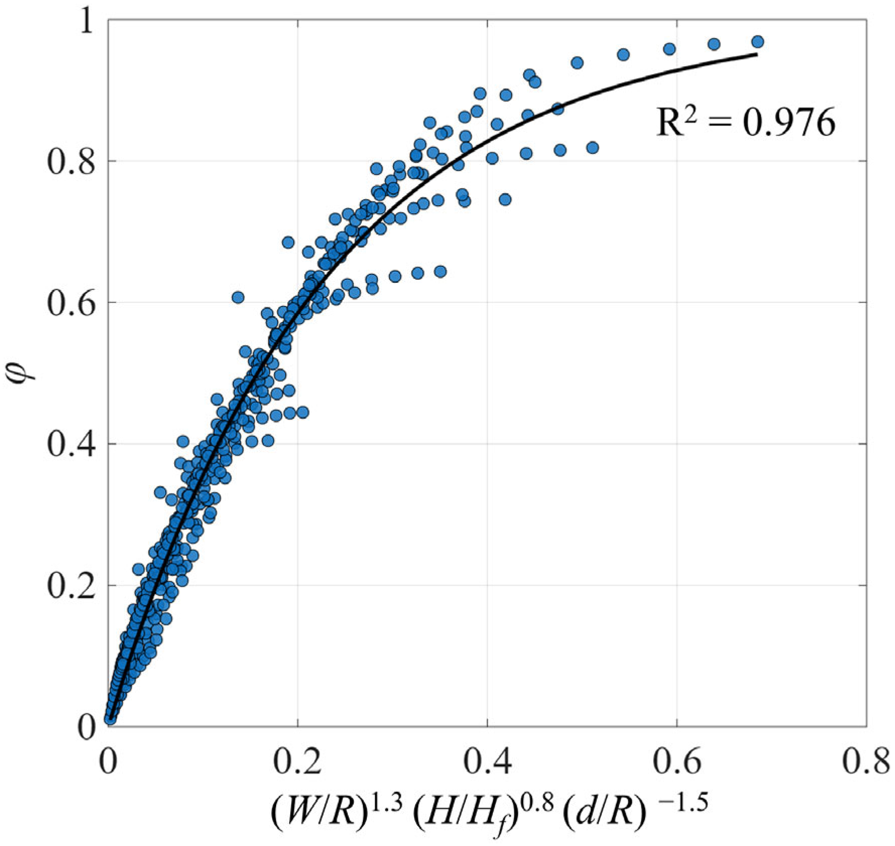
To further investigate the effects of obstacle geometry and the target–obstacle distance on the view factor, a shielding ratio, φ, is introduced to quantify the reduction in the flame radiation view factor caused by the obstacle, as defined in Equation (12). Since φ is dimensionless, its correlation is formulated using dimensionless independent variables. For the configurations examined in this study, φ can be expressed as a function of R, Hf, W, H and d, as shown in Equation (13). Among these parameters, R, d and W characterize the horizontal shielding relationship in the X–Y plane, whereas H and Hf characterize the vertical shielding relationship in the X–Z or Y–Z plane. Accordingly, these parameters are combined into the dimensionless groups, W/R, H/Hf and d/R, as given in Equation (14). It should be noted that once W or H exceeds its respective critical value, the obstructed view factor no longer changes with further increases, resulting in a change in the variation pattern of the shielding ratio. This makes it impractical to establish a single unified correlation for φ over the entire parameter range. Therefore, the fitting is restricted to the range W ≤ Wcr and H ≤ Hcr. Based on regression analysis of the computational results, the correlation takes the form given in Equation (15). The fitting results are presented in Figure 8, where the symbols denote the MC simulation results for each case and the solid lines represent the fitted curves from Equation (15). As shown, Equation (15) captures the variation trend of φ satisfactorily for all cases, with a coefficient of determination of R2 = 0.976, indicating high predictive accuracy. The functional form of Equation (15) reveals that increases in both W/R and H/Hf lead to an increase in the exponent term and, consequently, a higher φ, reflecting the physical expectation that larger obstacles produce a more pronounced shielding effect. This is consistent with the physical behavior of the obstructed view factor. In addition, an increase in d results in a decrease in φ. Physically, this is because as the target moves farther away from the obstacle, the solid angle subtended by the obstacle over the visible flame region decreases, thereby reducing the obscured area. Based on the above analysis, the final obstructed view factor can be calculated from F12 and φ, as expressed in Equation (16).
Figure 8.
Fitting results.
5. Limitations
This work reveals the influence of obstacles on the view factor from a theoretical analysis perspective. While certain progress has been made, there are still some limitations:
- (1)
- The present results have not yet been validated against experimental data. While this limitation does not undermine the main conclusions regarding the influence of obstacles on the view factor and radiative flux, it is important to address this gap when applying the results to practical fire risk assessment. Experimental validation would provide a more comprehensive evaluation of the model’s accuracy and robustness in real-world scenarios. Future work will focus on integrating experimental data to further validate and refine these findings, enhancing their applicability in fire risk modeling.
- (2)
- This study assumes uniformity in flame’s temperature, emissivity, and other characteristics, which may differ from real conditions. Considering the variation in these properties with height would improve the predictive accuracy of the model. Additionally, when an obstacle is located close to the flame, it can affect flame’s shape, which has been neglected in this work. Future studies should use experimental data to further investigate the impact of obstacles on the flame’s morphological characteristics and analyze the changes in view factor and radiative flux distribution.
- (3)
- The variables analyzed in the current work include the position and scale of the obstacles. The tank size affects the flame width, while the type of fuel influences the flame height, but these factors were not considered in this study. Therefore, the proposed equation may only be applicable to the specific conditions analyzed and its generalizability requires further validation. Future research should incorporate more influencing variables, aiming to develop a unified representation equation based on dimensional analysis.
6. Conclusions
In this study, the effects of obstacles on the radiative view factor and radiative flux in tank storage fire scenarios were systematically investigated using a cylindrical flame model combined with the Monte Carlo method. The main conclusions are as follows:
- (1)
- In the absence of obstacles, the contours of incident radiative flux exhibit circular symmetry around the flame. An obstacle partially blocks the radiation path from the flame to the target, causing the contours to deviate from this symmetric pattern. The radiative flux in the region behind the obstacle is significantly lower than that at the corresponding location under unobstructed conditions, and this attenuation becomes more pronounced as the target moves closer to the obstacle.
- (2)
- The obstructed view factor first decreases with increasing obstacle width (W) and then reaches a plateau, indicating the existence of a critical width (Wcr). Wcr is independent of obstacle height (H) but increases with the distance (d) between target and obstacle. A similar trend is observed for the effect of obstacle height, with a corresponding critical height (Hcr). Analytical expressions for Wcr and Hcr were derived based on geometric analysis.
- (3)
- A shielding ratio, φ, was defined to quantify the reduction in the view factor caused by the obstacle. Three dimensionless geometric parameters, W/R, H/Hf and d/R, were constructed using the flame radius and flame height as characteristic length scales. An exponential correlation for φ was established. The coefficient of determination between the predicted values and the Monte Carlo simulation results is R2 = 0.976, demonstrating that the proposed correlation provides good predictive accuracy.
Author Contributions
Conceptualization, X.L. and L.Z.; Formal analysis, X.L. and Q.M.; Investigation, C.L. and J.Z.; Writing—original draft, X.L. and L.Z.; Validation, Q.Z. All authors have read and agreed to the published version of the manuscript.
Funding
This research was funded by the National Key Research and Development Program of China (2023YFC3011300).
Data Availability Statement
Data availability upon request.
Conflicts of Interest
Authors Xuguang Li, Lei Zheng, Qiaotong Zhang and Jinbo Zhang were employed by the companies China National Aviation Fuel Group Limited and Beijing Aviation Oil Construction Co., Ltd. The remaining authors declare that the research was conducted in the absence of any commercial or financial relationships that could be construed as a potential conflict of interest.
References
- Ghasemi, A.M.; Nourai, F. A framework for minimizing domino effect through optimum spacing of storage tanks to serve in land use planning risk assessments. Saf. Sci. 2017, 97, 20–26. [Google Scholar] [CrossRef] [Scilit]
- Pantousa, D. Numerical study on thermal buckling of empty thin-walled steel tanks under multiple pool-fire scenarios. Thin-Walled Struct. 2018, 131, 577–594. [Google Scholar] [CrossRef] [Scilit]
- Robane, N.S.A.; Chong Vui San, M.; Md Said, M.S.; Mohd Tohir, M.Z. Parametric investigation of acetone liquid pool fire experi-ments on fire characteristics. Process Saf. Environ. Prot. 2025, 194, 604–618. [Google Scholar] [CrossRef] [Scilit]
- Chan Kim, S.; Lee, K.Y.; Hamins, A. Energy balance in medium-scale methanol, ethanol, and acetone pool fires. Fire Saf. J. 2019, 107, 44–53. [Google Scholar] [CrossRef] [Scilit]
- Ahmadi, O.; Mortazavi, S.B.; Pasdarshahri, H.; Mohabadi, H.A. Consequence analysis of large-scale pool fire in oil storage ter-minal based on computational fluid dynamic (CFD). Process Saf. Environ. Prot. 2019, 123, 379–389. [Google Scholar] [CrossRef] [Scilit]
- Elhelw, M.; El-Shobaky, A.; Attia, A.; El-Maghlany, W.M. Advanced dynamic modeling study of fire and smoke of crude oil storage tanks. Process Saf. Environ. Prot. 2021, 146, 670–685. [Google Scholar] [CrossRef] [Scilit]
- Rebec, A.; Plešec, P.; Kolšek, J. Pool fire accident in an aboveground LFO tank storage: Thermal analysis. Fire Saf. J. 2014, 67, 135–150. [Google Scholar] [CrossRef] [Scilit]
- Rebec, A.; Kolšek, J.; Plešec, P. Fires in storages of LFO: Analysis of hazard of structural collapse of steel–aluminium containers. J. Hazard. Mater. 2016, 306, 367–375. [Google Scholar] [CrossRef] [Scilit]
- Alinejad, F.; Bordbar, H.; Hostikka, S. Influence of detailed in-depth radiation modeling on the computational predictions of liquid pool burning rates. Fire Saf. J. 2024, 145, 104128. [Google Scholar] [CrossRef] [Scilit]
- Bathina, S.K.; Siddapureddy, S. Effect of spacing between the double pool fires on the flame emissivity and temperature. Fire Technol. 2023, 59, 2481–2497. [Google Scholar] [CrossRef] [Scilit]
- Deng, L.; Hou, Y.; Li, L.; Li, X.; Ren, F.; Liu, W.; Shi, C. Experimental study of local heat flux downstream of two adjacent pool fires: Effect of burner aspect ratio. Case Stud. Therm. Eng. 2025, 71, 106112. [Google Scholar] [CrossRef] [Scilit]
- Drysdale, D. An Introduction to Fire Dynamics, 3rd ed.; John Wiley & Sons: Chichester, UK, 2011. [Google Scholar]
- Hurley, M.J.; Gottuk, D.; Hall, J.R.; Harada, K.; Kuligowski, E.; Puchovsky, M.; Torero, J.; Watts, J.; Wieczorek, C. (Eds.) SFPE Handbook of Fire Protection Engineering; Springer: New York, NY, USA, 2016. [Google Scholar]
- Mudan, K.S. Thermal radiation hazards from hydrocarbon pool fires. Prog. Energy Combust. Sci. 1984, 10, 59–80. [Google Scholar] [CrossRef] [Scilit]
- Guelzim, A.; Souil, J.M.; Vantelon, J.P. Suitable configuration factors for radiation calculation concerning tilted flames. J. Heat Transf. 1993, 115, 489–492. [Google Scholar] [CrossRef] [Scilit]
- Pinto, P.E.; Littin, M. Improving radiation estimation from circular pool fires through field-of-view angle analysis. Int. J. Heat Mass. Transf. 2026, 258, 128312. [Google Scholar] [CrossRef] [Scilit]
- Ding, C.; Han, G.; Li, M.; Guan, J.; Wang, Z. A new-proposed multi-inclined-cylinder radiation model of rectangular pool fire of heptane in longitudinal winds. Int. J. Therm. Sci. 2023, 184, 107912. [Google Scholar] [CrossRef] [Scilit]
- Li, B.; Wan, H.; Ding, L.; Ji, J. Predicting radiative heat fluxes from two buoyant turbulent diffusion flames from burning pro-pane under cross wind. Proc. Combust. Inst. 2021, 38, 4897–4906. [Google Scholar] [CrossRef] [Scilit]
- Chen, X.; Ding, Z.; Lu, S. Investigation of sidewall height effect on the burning rate and flame tilt characteristics of pool fire in cross wind. Fire Saf. J. 2021, 120, 103111. [Google Scholar] [CrossRef] [Scilit]
- Huang, X.; Wang, Y.; Zhu, H.; He, L.; Tang, F.; Wen, J. Experimental study on the radiant heat flux of wall-attached fire plume generated by rectangular sources. Int. J. Therm. Sci. 2021, 159, 106605. [Google Scholar] [CrossRef] [Scilit]
- Chen, J.; Wang, D.; Guo, L.; Wang, Z.; Kong, D. Experimental study on flame morphology and flame radiation of pool fire shel-tered by plate obstacle. Process Saf. Environ. Prot. 2022, 159, 243–250. [Google Scholar] [CrossRef] [Scilit]
- Chen, J.; Song, Y.; Yu, Y.; Xiao, G.; Tam, W.C.; Kong, D. The influence of a plate obstacle on the burning behavior of small scale pool fires: An experimental study. Energy 2022, 254, 124223. [Google Scholar] [CrossRef] [Scilit]
- Thomas, P.H. The size of flames from natural fires. Symp. Int. Combust. 1963, 9, 844–859. [Google Scholar] [CrossRef] [Scilit]
- Karlsson, B.; Quintiere, J.G.; Johansson, N. Enclosure Fire Dynamics, 2nd ed.; CRC Press: Boca Raton, FL, USA, 2022. [Google Scholar]
- Mudan, K.S. Geometric view factors for thermal radiation hazard assessment. Fire Saf. J. 1987, 12, 89–96. [Google Scholar] [CrossRef] [Scilit]
- Howell, J.R.; Mengüç, M.P.; Daun, K.; Siegel, R. Thermal Radiation Heat Transfer, 7th ed.; CRC Press: Boca Raton, FL, USA; Taylor & Francis Group: London, UK; New York, NY, USA, 2021. [Google Scholar]
- GB/T 37243-2019; Determination Method for External Safety Protection Distance of Hazardous Chemicals Production Unit and Storage Facility. Standards Press of China: Beijing, China, 2019. (In Chinese)
- Li, X.; Zhang, M.; Zhong, Y.; Li, X.; Wang, H.; Ding, Y. Upwind thermal radiation prediction of multi-scale aviation kerosene pool fire on the flight deck for emergency rescue: Experiment, numerical simulation and machine learning. Int. J. Therm. Sci. 2023, 190, 108308. [Google Scholar] [CrossRef] [Scilit]
- Zhao, J.; Zhang, Q.; Wang, Z.; Yang, R.; Zhang, J. Continuous boilover behaviors of large-scale kerosene pool fires under sub-atmospheric pressure. Process Saf. Environ. Prot. 2023, 177, 1431–1439. [Google Scholar] [CrossRef] [Scilit]

Disclaimer/Publisher’s Note: The statements, opinions and data contained in all publications are solely those of the individual author(s) and contributor(s) and not of MDPI and/or the editor(s). MDPI and/or the editor(s) disclaim responsibility for any injury to people or property resulting from any ideas, methods, instructions or products referred to in the content. |
© 2026 by the authors. Licensee MDPI, Basel, Switzerland. This article is an open access article distributed under the terms and conditions of the Creative Commons Attribution (CC BY) license.