


Abstract
The outdoor transformer protection performance of fine water mist, which is widely applied to indoor electrical fire protection, is strongly affected by ambient wind. In this study, the effect of imposed wind speed on water mist distribution was quantified through a full-scale cold spray experiment conducted using a 110 kV transformer in a large wind-tunnel facility. Two nozzle configurations with flow coefficients of 2.0 and 1.7, which corresponded to nominal single-nozzle flow rates of 20 and 17 L/min, respectively, at a terminal operating pressure of 10 MPa, were tested at imposed wind speeds of 0, 4, 6, 8, and 10 m/s. Fifty-eight water collection boxes were used, including 54 boxes on the transformer sidewall and four boxes on the top surface, and the spray duration for each condition was 30 s. The wind-induced redistribution of the mist became evident at 4 m/s and intensified with increasing wind speeds. Water deposition generally decreased on the windward side and shifted toward the downwind region, while the response of the top surface differed because of geometric obstruction and the combined contribution of multiple nozzles. At the same wind speed and operating pressure, the K = 2.0 nozzle configuration maintained a more favorable spray distribution than the K = 1.7 configuration. These full-scale cold spray data clarify the wind sensitivity of outdoor transformer water mist systems and provide an experimental basis for subsequent fire tests and wind-protection design.
1. Introduction
Power transformers are critical assets in transmission and distribution networks, and their reliable operation is essential for maintaining power-system continuity. Oil-immersed transformers contain a substantial inventory of combustible insulating oil and may develop pool, spray, or flowing fires after insulation failure, electrical faults, or mechanical damage [1,2,3,4,5,6]. Because transformer fires can threaten adjacent equipment and grid availability, fixed fire-protection systems are required to rapidly suppress fire development while limiting secondary damage [7,8,9,10,11,12,13].
Water spray, foam, oil-drainage/nitrogen-injection systems, and fine water mist have all been considered for transformer fire protection [14,15,16,17,18,19]. Fine water mist is attractive because small droplets provide strong cooling, evaporation, and radiation attenuation while requiring less water than conventional deluge systems. Studies have established the principal suppression mechanisms and design sensitivities of water mist systems, including the roles of droplet transport, water flux, obstruction, ventilation, and fire geometry [20,21,22,23,24]. Additionally, full-scale transformer-room experiments have demonstrated the potential of water mist for transformer fire suppression and post-fire cooling [25], while standards such as NFPA 750 represent international design practice [26]. These studies show that water mist performance is inherently coupled to the surrounding flow field; therefore, the transfer of indoor water mist technology to outdoor transformer protection must consider wind-induced droplet drift.
Previous studies on transformer fires have mainly addressed transformer-oil combustion characteristics, suppression effectiveness, nozzle arrangement, or numerical prediction [27,28,29,30,31,32,33,34,35,36,37,38]. For outdoor transformers, however, ambient wind can deflect droplets away from the intended target and redistribute water between the windward, leeward, and top surfaces. This is particularly important for a full-size transformer because the equipment body, bushings, and other components create complex shielding and wake regions that cannot be adequately represented by small laboratory targets. Although several studies have examined water mist suppression for transformers, quantitative full-scale information on the variation in local spray intensity with imposed wind speed remains limited.
Therefore, the usage of fine water mist for outdoor oil-immersed transformer fire exhibits some limitations, and its universality needs to be further engineered and tested, specifically for the effect of the wind speed on the spray intensity. If the transformer has a sheltered part of the spray nozzle, spray validity is unclear. Therefore, in this study, a 110 kV transformer was used to construct an experimental platform. To analyze the influence of the different imposed wind speeds on the spray intensity of the transformer fine water spray system, fine water spray nozzles with flow coefficients of 2.0 (20 L/min) and 1.7 (17 L/min) and five different wind speeds were considered during the cold spray experiment, and 58 water collection boxes were set up to collect water from the cold spray of the fine water spray system.
2. Transformer Cold Spray Experiment Overall Program Design
2.1. Cold Spray Experiment Wind Field Environment Design
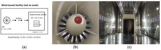
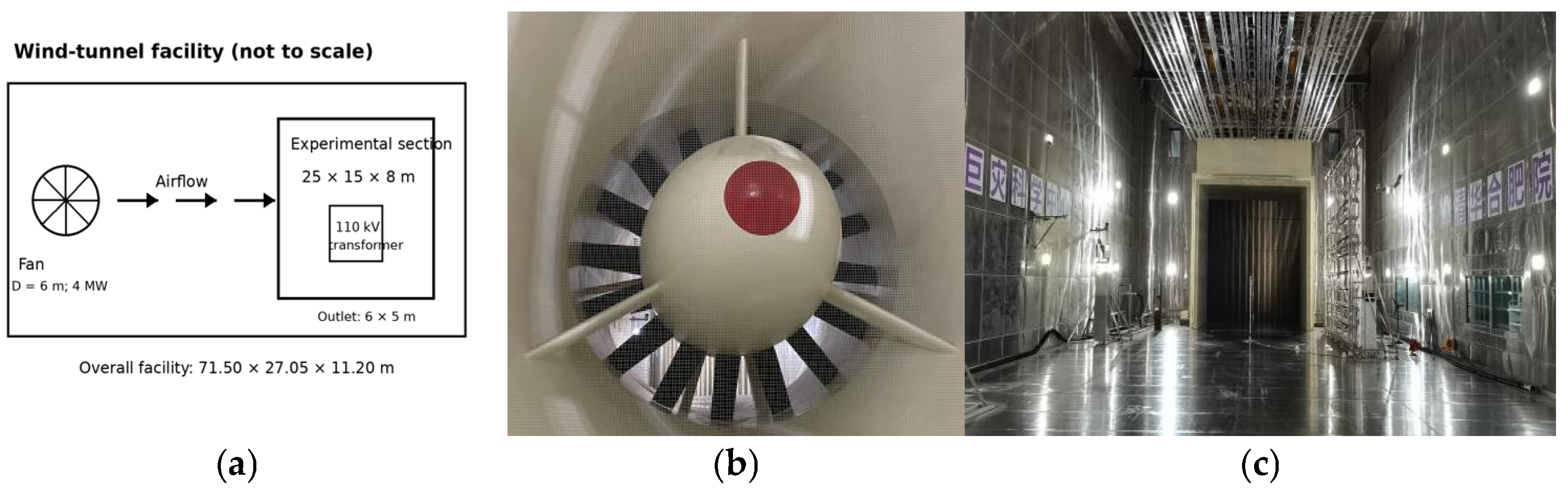
A multi-hazard coupled environment wind tunnel test platform was built, whose length, width, and height were 71.50 m, 27.05 m and 11.20 m, respectively, as shown in Figure 1a. The length, width and height of the experimental section were 25 m, 15 m and 8 m, respectively (Figure 1b). All the experiments involving the fine water spray cold spraying experiments were performed in this experimental section. The wind field environment required for the experiment was provided by the fan in the experimental platform, which had a diameter of 6 m and power of 4 MW and provided a stable wind speed environment throughout the experiment. Figure 1c shows the exit of the experimental wind tunnel, whose width and height were 6 m and 5 m, respectively.
Figure 1.
Transformer cold spray experiment platform. (a) Schematic of the wind tunnel for the multi-hazard coupled environment; (b) wind tunnel fan; (c) wind tunnel test section.
2.2. Test Transformer
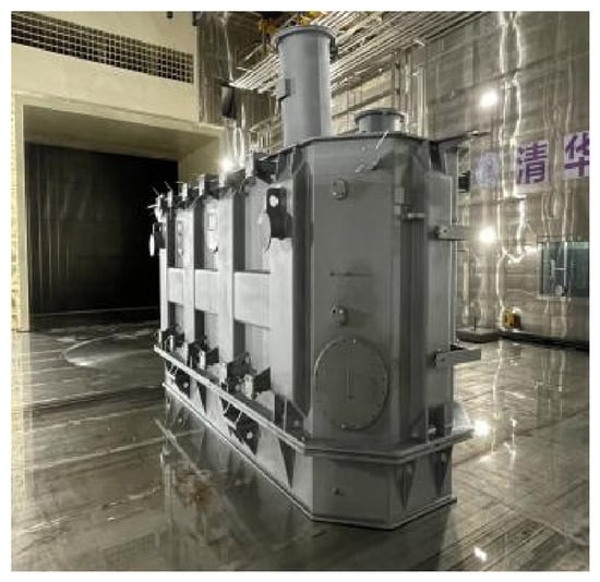
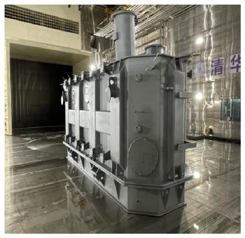
A 110 kV power transformer was used as the full-scale test object. Its overall dimensions were 6.15 × 1.96 × 3.10 m (length × width × height), while its body was 1.80 m above the ground, and its total mass was approximately 11 t. The transformer was positioned in the experimental section downstream of the wind-tunnel outlet. Figure 2 shows the transformer and its local placement; the dimensions shown therein indicate the local transformer arrangement.
Figure 2.
Transformer location diagram.
2.3. Fine Water Mist System Design
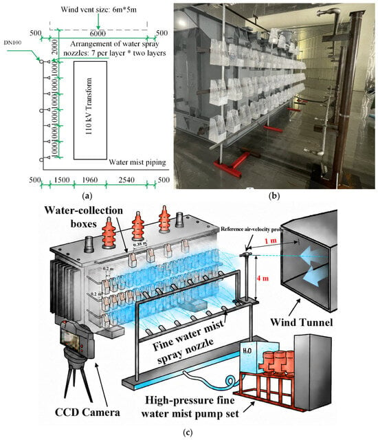
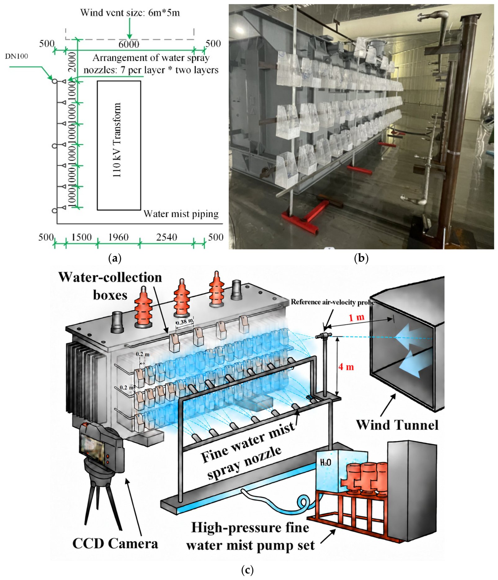
The water _mist system consisted of two pipe-network levels surrounding the transformer. The lower and upper nozzle elevations were 0.75 m and 2.0 m, respectively, with seven nozzles on each level and a nominal nozzle spacing of 1 m, resulting in a total of 14 nozzles (Figure 3). The arrows and dashed lines in Figure 3a respectively repre-sent the length and height of the fine water mist nozzle arrangement. The arrows and dashed lines in Figure 3c respectively represent the distance from the wind tunnel to the wind speed probe and the height to the fine water mist nozzle. Two nozzle flow coefficients were investigated, K = 2.0 and K = 1.7, and the corresponding nominal sin-gle-nozzle flow rates at the terminal operating pressure of 10 MPa (100 bar) were 20 and 17 L/min, respectively. The rated system pressure was 14 MPa, while the operating pressure of the terminal nozzle used in the experiments was 10 MPa. Each spray test lasted 30 s.
Figure 3.
Design and arrangement of the fine water mist spray nozzle system. (a) Design drawing of the nozzle points for the fine water mist system; (b) layout of sprinkler points for the fine water mist system; (c) diagram of the experimental rig.
2.4. Test Conditions and Variable Definitions
The experimental matrix consisted of two nozzle flow coefficients and five imposed wind speeds, resulting in ten full-scale cold spray conditions (Table 1). The wind speed, nozzle flow coefficient, terminal nozzle pressure, and nominal single-nozzle flow rate are denoted by U (m/s), K, pn, and Qn, respectively. For the tested nozzles,
when the pressure p is expressed in bars; therefore, at pn = 100 bar (10 MPa), K = 2.0 and 1.7 correspond to Qn = 20 and 17 L/min, respectively. The 0 m/s condition was used as the no-wind baseline, while the 4–10 m/s conditions were selected to progressively increase the imposed crossflow and identify the wind-induced redistribution within the operating range of the wind-tunnel facility. The two K values were compared at the same pressure and layout to evaluate the effect of nozzle discharge capacity on wind without changing the system geometry. Each experiment was repeated three times to ensure the accuracy of the results.
Table 1.
Experimental test settings.
Each experimental condition was independently repeated three times (n = 3) to assess experimental repeatability. The data from each repetition were processed separately using the same data-processing procedure, and the reported values were calculated as the arithmetic mean of the three independent measurements. Standard deviation (SD) was used to characterize the variation between replicates.
The coefficient of variation (CV) was calculated where applicable to quantify the normalized variability across replicate runs.
For the ten test conditions, CV values of the measured spray collection rate ranged from 2.1% to 6.8%, demonstrating good repeatability of the measurements.
2.5. Wind Speed Measurement System and Fine Water Mist Collection Arrangement
- (1)
- Wind Speed Measurement
The imposed wind speed was measured using a multi-channel anemometer (Kanomax), whose measurement range and accuracy were 0–50 m/s and 1%, respectively, as shown in Table 2. As shown in Figure 3c, the reference air-velocity probe was positioned on the central vertical plane of the test section, 1 m upstream of the windward edge of the transformer, 3.5 m downstream of the wind-tunnel outlet, and 4 m above the floor. The sensing direction of the probe was aligned with the incoming airflow. This position was selected to measure the approaching airflow while avoiding interference from the transformer wake and the water mist spray. The same probe position and data-processing procedure were used for all experimental conditions.
Table 2.
Key equipment and measurement specifications.
- (2)
- Fine Water Mist Collection Arrangement
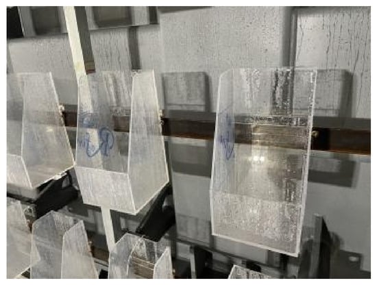
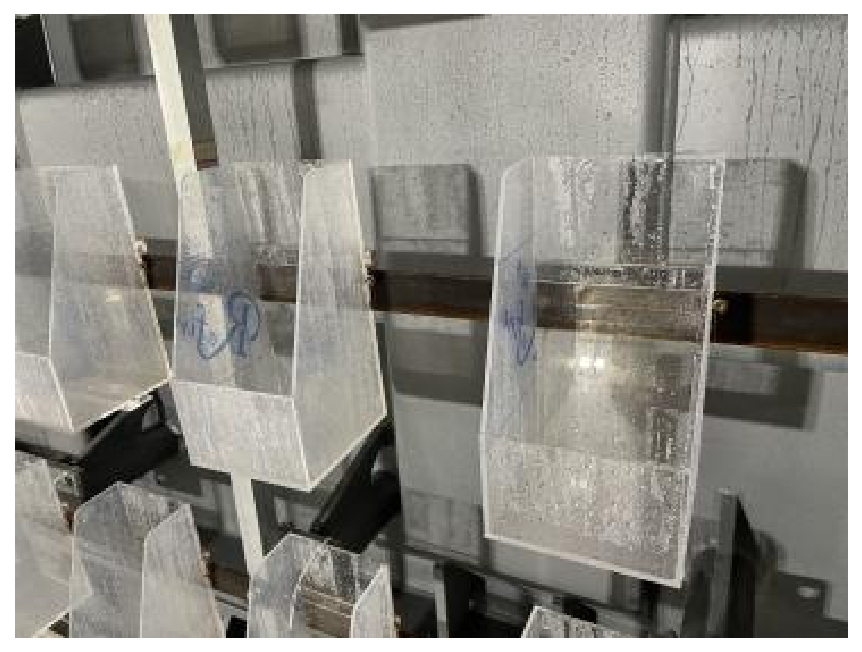
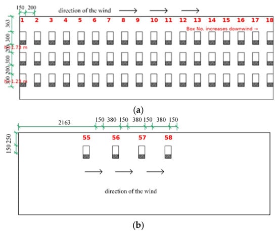
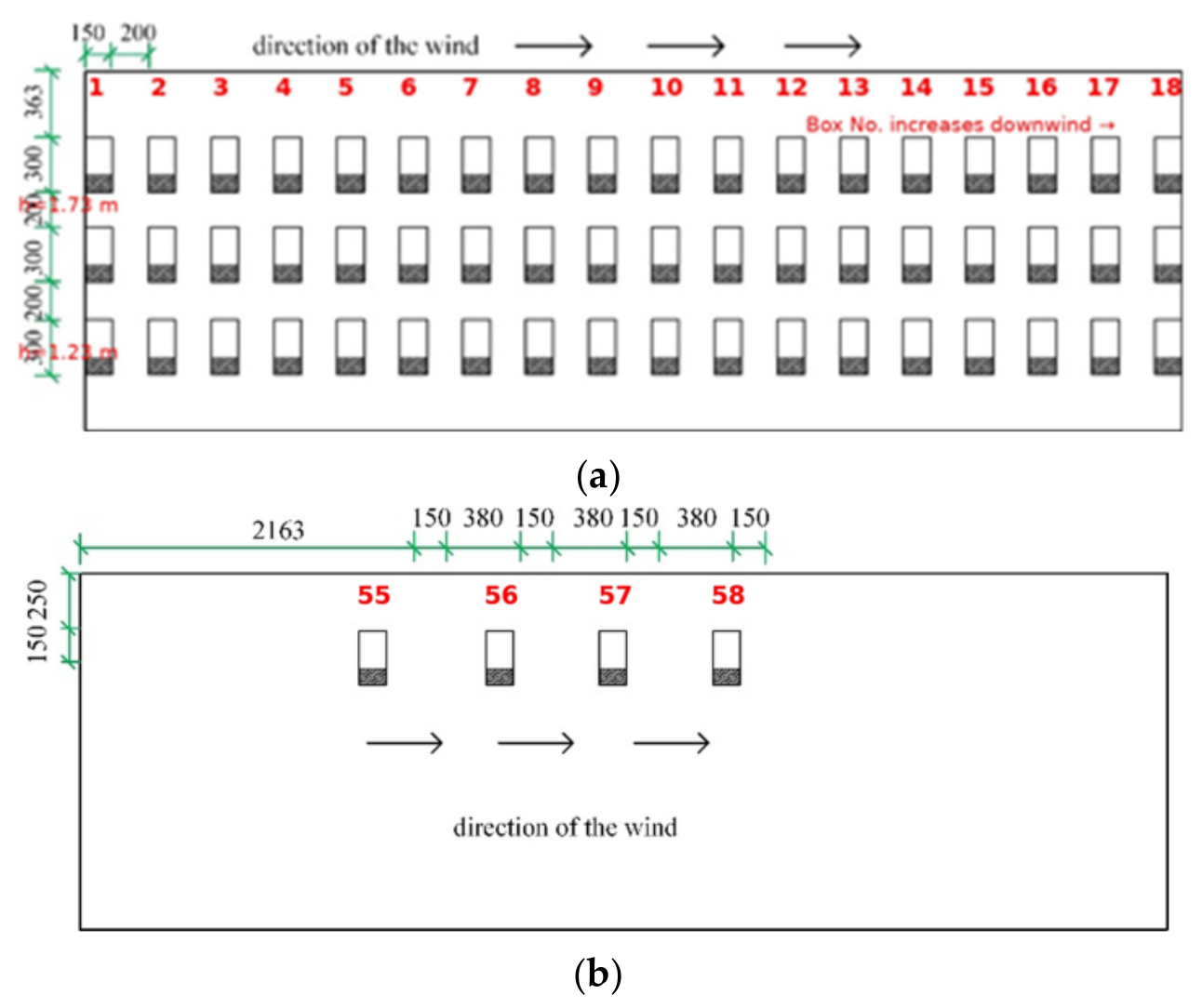
Water deposited on the transformer was collected using individual water-collection boxes. The bottom footprint, front baffle, and rear baffle of each box were 0.15 × 0.15 m, 5 cm, and 30 cm, respectively (Figure 4). Fifty-four boxes were arranged on the transformer sidewall in three horizontal rows of 18 boxes at elevations h = 0.73 m, 1.23 m, and 1.73 m. The rows were separated vertically by 0.50 m. Four additional boxes were placed on the top surface of the transformer at h = 2.23 m, resulting in a total of 58 collection boxes (Figure 5). The box numbering, which increased in the downwind direction, is indicated in Figure 5 to provide a direct spatial correspondence with Figure 6. After each 30-s spray test, the amount of water collected in each box was determined and converted to the local spray intensity. The nominal local spray intensity (in L·s−1·m−2) at box i is defined as:
where is the collected water volume (L), = 0.15 × 0.15 m = 0.0225 m2 is the nominal collection area, and = 30 s is the spray duration.
Figure 4.
Water collecting box.
Figure 5.
Layout diagram of water collecting box. (a) Schematic of the transformer side catchment box arrangement. (b) Schematic of the water collecting box on the top of the transformer.
Figure 6.
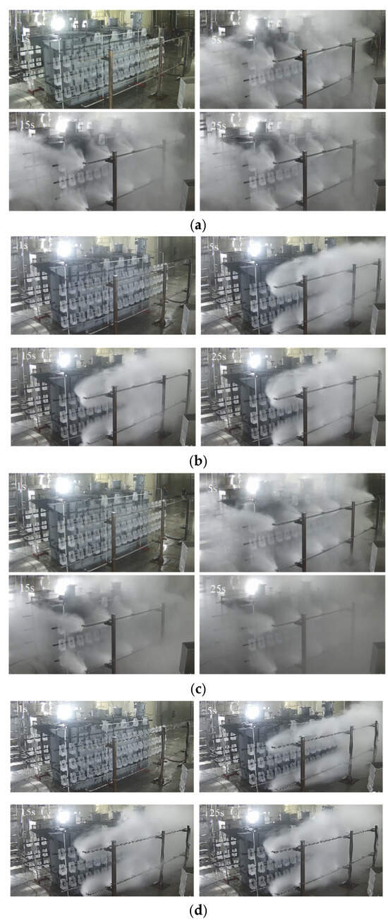
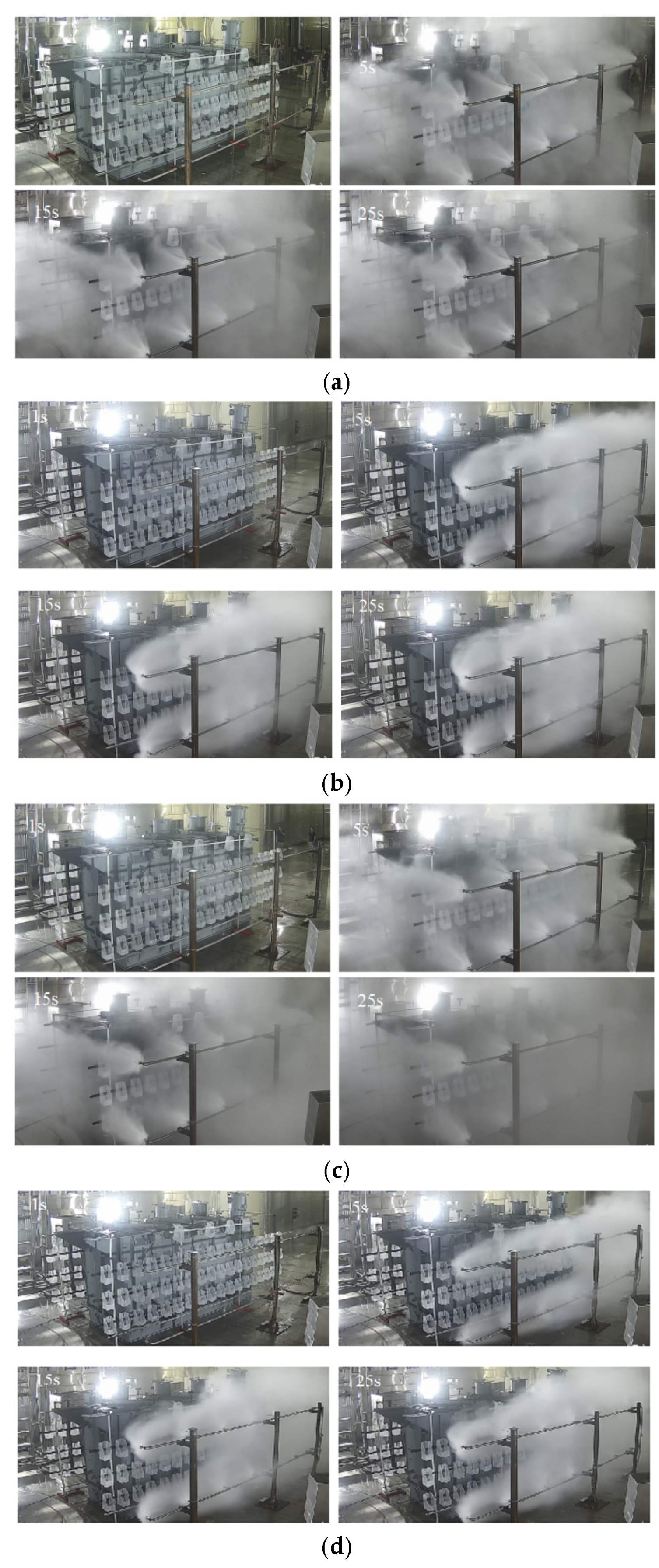
Representative water mist spray behavior. (a) K = 2.0, U = 0 m/s; (b) K = 2.0, U = 10 m/s; (c) K = 1.7, U = 0 m/s; (d) K = 1.7, U = 10 m/s.
3. Transformer Fine Water Spray Cold Spray Experiment and Analysis
Figure 6 shows the experimental process of fine water mist cold spray under different conditions. The spray images indicate that the water mist cloud moves downstream under the influence of wind speed. As shown in Figure 6a,b, on the windward side, the water mist encounters difficulties in passing through the wind flow and reaching the protected area (collecting tank); conversely, the water mist accumulates on the leeward side owing to the ambient wind. Comparing the spray effects of the different flow coefficients in Figure 6b,d, the spray flow with K = 2.0 is significantly higher than that with K = 1.7.
4. Results and Analysis
4.1. Droplet Size
The droplet size is a microscopic parameter that characterizes the fine water mist field and is a commonly used factor that describes droplet size and distribution patterns [39] and directly determines the intensity of the fine water mist field. According to Chapter 7, “Test Methods,” of the standard GB/T 26785-2011 [40], the fine water mist droplet size must be tested using a laser particle size analyzer, with the measurement point located on a plane 1 m below the central axis of the fine water mist nozzle. A laser particle size analyzer utilizes the principles of light scattering and diffraction to calculate droplet size by analyzing the correlation between the spatial distribution of scattered light angles and particle size. In general, the droplet size of a fine water mist is negatively correlated with the scattered light angle; therefore, larger droplets scatter a higher proportion of light at small angles. The calculation employs the Mie theory of scattered light intensity distribution [33]:
In Equation (3), is the central intensity of the incident laser (W/m2); is the wavelength of the incident laser (m); r is the distance from the observation point to the center of the particle (m); and and are the components of the scattered light intensity perpendicular to and parallel to the scattering plane, respectively, which can be obtained by summing the Mie scattering coefficients using an angular function series:
In Equations (4) and (5), the angular functions and are typically calculated using the Legendre functions and used to analyze the characteristics of the scattering angle. and describe the light scattering and absorption characteristics of the fog droplets, respectively, and are related to the relative refractive index m of the fog droplets with respect to the surrounding air and the size parameter . They are generally calculated using the spherical Bessel function and Hankel function :
Based on the above calculation process and the fact that the light scattered by water mist droplets of different sizes obeys the principle of linear superposition, we can conclude that the scattered light intensity received by each channel of the detector of the laser particle size analyzer corresponds to the scattering contribution of fine water mist droplets of different sizes. Consequently, a set of linear equations relating light intensity response to fine water mist droplet size can be established. The droplet size distribution characteristics can be determined using a regularization method for inverse calculations, and characteristic parameters such as cumulative volume diameters (e.g., Dv50 and Dv99) can be further derived.
In accordance with the requirements of GB/T 26785-2011, the droplet sizes from the nozzles used in this experiment were tested. A laser beam was passed perpendicularly through the fine water mist field 1 m directly below the nozzle, and the scattered light was focused by a Fourier lens and transmitted into an annular photodetector. Subsequently, the results were obtained using a data-processing unit that performed the particle size inversion calculations. Dv50 and Dv99 were selected as the two characteristic parameters that described the test results; the specific data are presented in Table 3.
Table 3.
Water mist droplet size.
4.2. Initial Velocity of the Droplet
The droplet intensity of fine water mist is related to the initial droplet velocity [39]. The droplet velocity vm can be determined from the relationship between the fine water mist flow rate and total cross-sectional area of the nozzle . Because a six-hole nozzle is used in this study, the following equation must be satisfied:
In this study, the six-hole nozzles with flow coefficients of 1.7 and 2.0 corresponded to orifice diameters of 0.86 mm and 0.90 mm, respectively. The nozzle cross-sectional area is calculated using the above orifice diameters:
The droplet velocity is positively correlated with the flow coefficient. The droplet velocities were 81.3 m/s and 87.4 m/s for the nozzles with flow coefficients of 1.7 K and 2.0 K, respectively.
4.3. Sidewall Spray Intensity Distribution
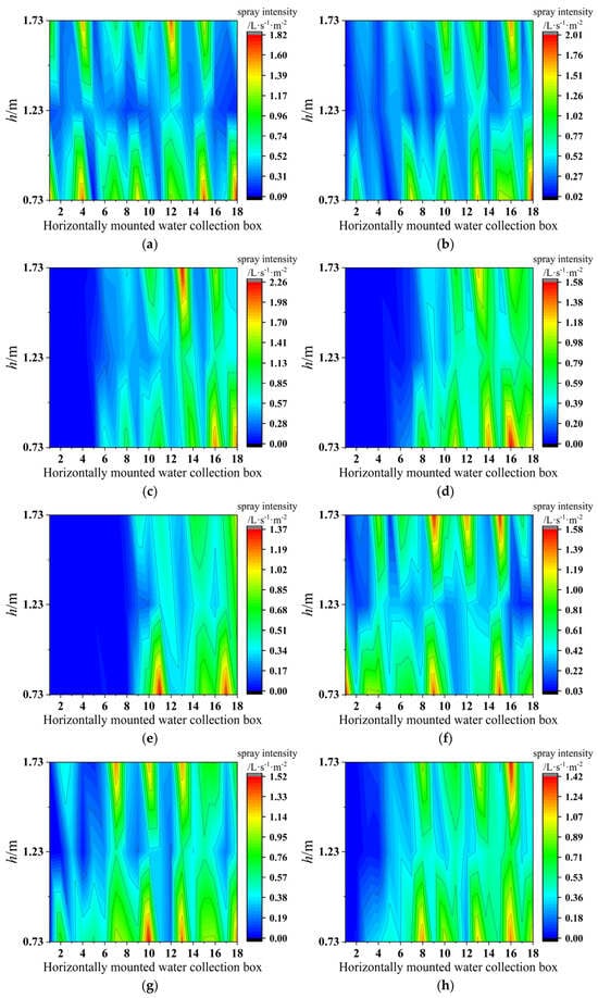
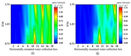
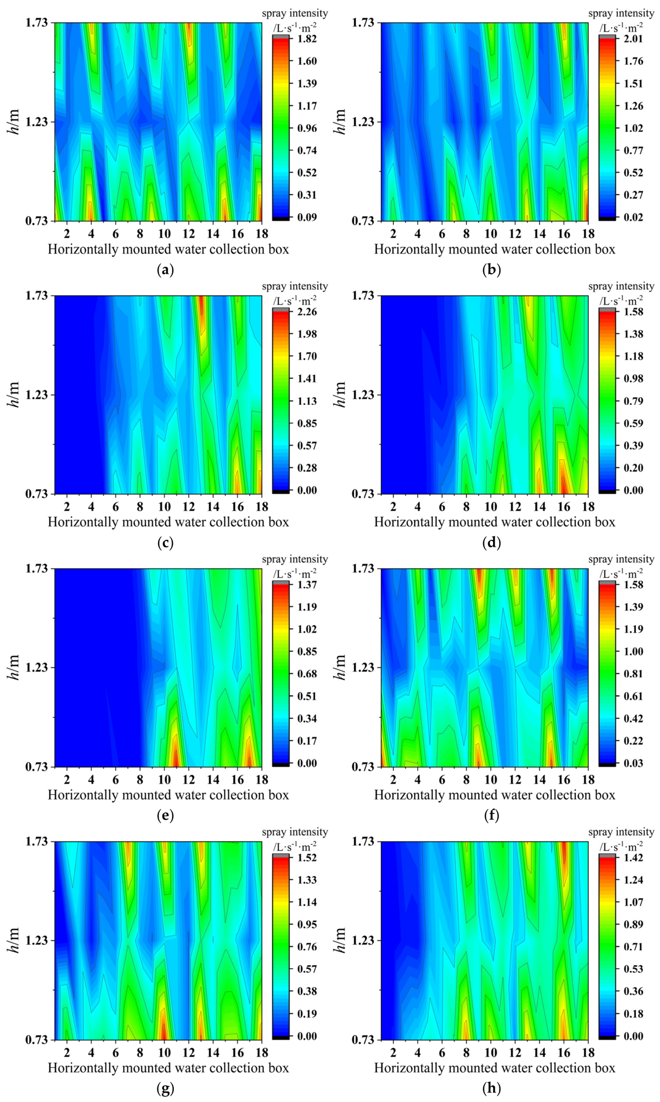
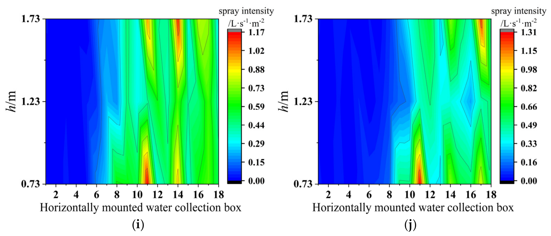
For each test, the 54 sidewall collection boxes provided a spatial map of the local spray intensity across the three elevations. Figure 7 presents the measured distribution for all ten test conditions. The horizontal box number increases from the upwind side toward the downwind side. Wind speed significantly affects the distribution of fine water mist flux density. The mist flux density exhibits an accelerating decay trend at wind speeds higher than 6 m/s. Furthermore, this decay trend is related to the initial velocity and particle size distribution of the fine water mist droplets; droplets exhibit greater ability to resist airflow disturbances at higher initial velocities and for coarser particle sizes. Windy conditions alter the spatial distribution pattern of the water mist flux, gradually shifting from the symmetrical, uniform distribution observed under calm conditions to an asymmetrical distribution shifted toward the downwind direction. Within the protected area, a pattern characterized by insufficient coverage on the windward side and accumulation on the leeward side is produced.
Figure 7.
Spatial distribution of the sidewall spray intensity. The horizontal collection box number increases in the downwind direction as defined in Figure 5. (a–e) K = 2.0 at U = 0 m/s, 4 m/s, 6 m/s, 8 m/s, and 10 m/s, respectively; (f–j) K = 1.7 at U = 0 m/s, 4 m/s, 6 m/s, 8 m/s, and 10 m/s, respectively.
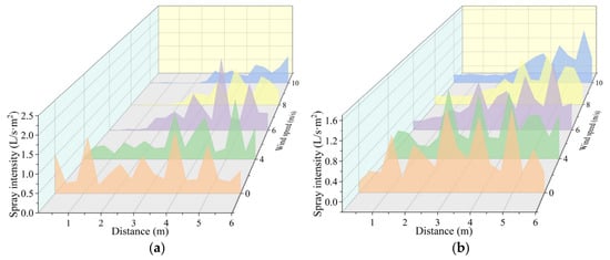
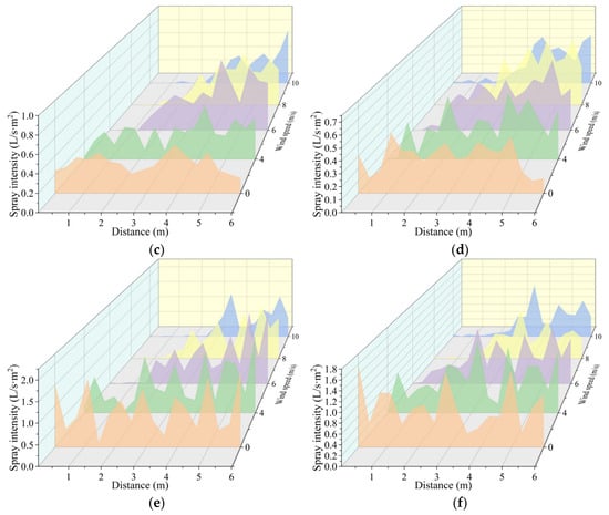
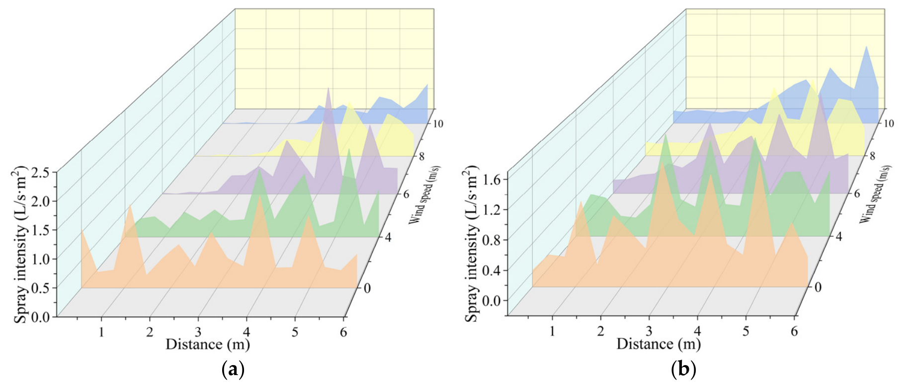
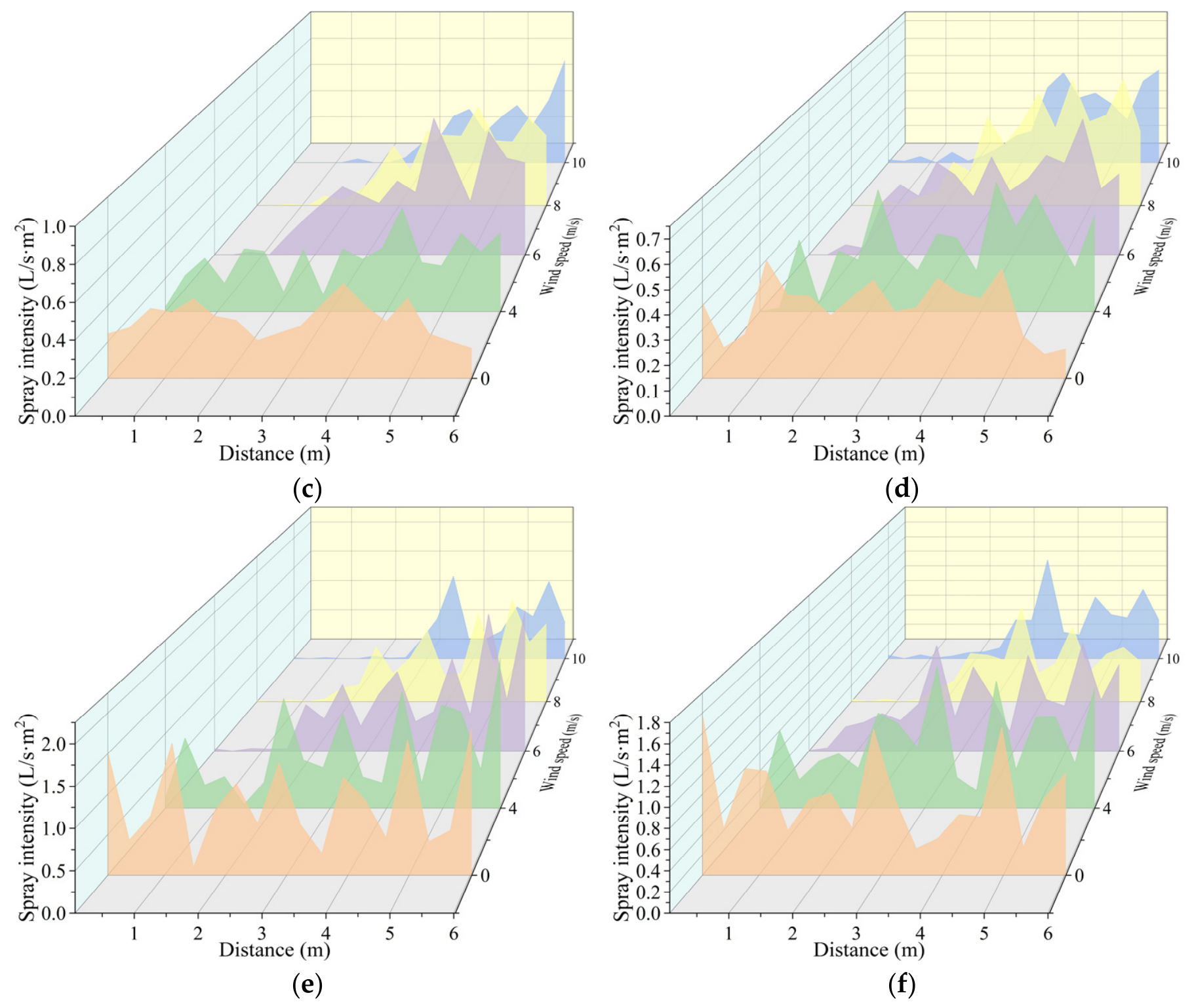
Figure 8 compares the spray-intensity profiles along the sidewall at h = 1.73, 1.23, and 0.73 m. These three elevations were selected because they correspond to the three sidewall collection rows. And the orange, green, purple, yellow, and blue color in Figure 8 represent the corresponding intensities of water spray at wind speeds of 0 m/s, 4 m/s, 6 m/s, 8 m/s, and 10 m/s, respectively. At h = 1.73 m, wind-induced redistribution becomes apparent from the 4 m/s condition, and the upstream portion of the sidewall experiences a pronounced reduction in the collected water as U =10 m/s. At h = 1.23 m, the same progressive downwind displacement is with increasing wind speeds, although the no-wind spray intensity is lower than that at h = 1.73 m. At h = 0.73 m, the effect of the combined coverage of the two nozzle levels on the collection row produces relatively high local spray intensities. With increasing wind speeds, water deposition is increasingly transferred from the windward region toward the downwind region. For the same operating pressure and wind speed, the K = 2.0 configuration generally retains a more favorable sidewall distribution than the K = 1.7 configuration.
Figure 8.
Sidewall spray intensity profiles at the three measurement elevations. (a) K = 2.0, h = 1.73 m; (b) K = 1.7, h = 1.73 m; (c) K = 2.0, h = 1.23 m; (d) K = 1.7, h = 1.23 m; (e) K = 2.0, h = 0.73 m; (f) K = 1.7, h = 0.73 m. The spray intensity is in L·s−1·m−2.
4.4. Spray Intensity on the Transformer Top Surface
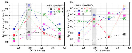
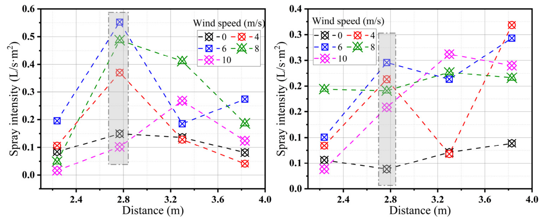
At the top of the transformer, that is the casing, obstructions due to the top of the relevant electrical components of the obstruction and the spray nozzle and the transformer charged distance limitations may affect the actual spraying effect of the water mist system and the intensity of the fine water mist spray. The top four water collection boxes are located in the middle of the transformer, which is under the influence of multiple spray nozzles, while the upwind spray nozzle spray water mist in the wind under the action of the wind will be offset to the downwind direction, resulting in water mist being downwind by the external wind field and spray nozzle spray being double the force, resulting in the top water collection box in the external wind speed when the amount of water collected compared to the wind will increase, which will lead to the intensity of spraying increasing. In addition, as shown in Figure 9, for nozzle configurations of K = 2.0 and K = 1.7 and wind speeds of 4 m/s, 6 m/s, and 8 m/s, the role of its range of oil-immersed power transformer in the middle of the 2.8 m or so. The grey shadow in Figure 9 represents the turning points of water spray intensity at different distances. And after the region of the spray intensity, is a significant decline in the trend; at a wind speed of 10 m/s, the role of its range can reach approximately 3.3 m, and the region of the subsequent reduction in the strength of spraying is the impact of wind speed.
Figure 9.
Spray intensity of the fine water mist at the top of transformer (h = 2.23 m).
4.5. Discussion
The full-scale measurements demonstrate that an externally imposed crossflow changes the spatial deposition pattern rather than simply reducing the total effectiveness of the spray. Water mist transport depends on the competition between droplet inertia, spray-induced momentum, gravitational settling, aerodynamic drag, and interception by equipment surfaces. Classic water mist studies have emphasized that the droplet size, momentum, ventilation, and obstruction strongly influence the ability of water mist to reach a target [25,36,37,38,39]. In the present tests, increasing U shifted the spray field toward the downwind direction, producing lower deposition on parts of the windward sidewall and locally higher deposition farther downstream. The top surface responded differently because droplets deflected by the crossflow were intercepted by the transformer casing and upper components. Therefore, the measured response was spatially non-uniform and depended on both the imposed flow and transformer geometry. In addition, the nozzle discharge capacity was crucial for this distribution. At the same terminal pressure of 10 MPa, the nominal single-nozzle flow rates of the K = 2.0 and K = 1.7 nozzle configurations were 20 L/min and 17 L/min, respectively. Furthermore, the K = 2.0 configuration generally maintained a more favorable distribution under the same imposed wind speed. This result is consistent with the expectation that a larger discharge capacity can increase the total liquid transport available to resist crossflow.
5. Limitations
This study had several limitations. First, all tests were cold spray experiments, without any fire plume, thermal radiation, droplet evaporation, or vapor generation during the experiments. Therefore, the measured distribution patterns reflected the hydraulic transport characteristics under wind conditions rather than fire-extinguishing performance. Second, the study examined only one full-scale 110 kV transformer geometry, one nozzle arrangement, two nozzle flow coefficients, and wind speeds of 0–10 m/s. Future work will focus on multiple wind directions and fire experiments in which the applied wind is coupled with the smoke plume from a transformer fire.
6. Conclusions
A full-scale cold spray study was conducted on a 110 kV transformer to quantify the influence of the imposed wind speed on the spatial distribution of a high-pressure water mist system. Ten conditions were tested using K = 2.0 and 1.7 nozzles at U = 0, 4, 6, 8, and 10 m/s, with a terminal nozzle pressure of 10 MPa and spray duration of 30 s. The major conclusions are summarized below:
(1) Under the tested conditions, the transition from the no-wind case to U = 4 m/s exhibited the first clear signs of wind-induced redistribution, and the displacement of the mist progressively strengthened when U was 6–10 m/s. The effect was spatially non-uniform: water deposition decreased at several windward locations while increasing farther downwind.
(2) The three sidewall measurement elevations (h = 0.73 m, 1.23 m, and 1.73 m) exhibited different absolute spray intensities accompanied by a consistent wind-driven shift toward the downwind direction.
(3) On the top surface, the wind redirected droplets from upstream nozzles toward the transformer casing and upper components. The principal influence range was approximately 2.8 m when U was 4–8 m/s and extended to approximately 3.3 m when U was 10 m/s.
(4) At the same operating pressure of 10 MPa and wind speed of 0–10 m/s, the K = 2.0 nozzle configuration (20 L/min nominal flow per nozzle) generally maintained a more favorable spray distribution than K = 1.7 (17 L/min).
To optimize and improve the design of the fine water spray system and optimize the firewall height to provide a scientific basis for the practical application of the proposed approach, future research should include a comprehensive study of the fine water spray system when applied to an actual outdoor transformer fire.
Author Contributions
Conceptualization, X.S. and S.L.; methodology, X.S. and S.L.; software, X.S. and S.L.; validation, X.S. and S.L.; formal analysis, X.S. and S.L.; investigation, X.S. and S.L.; resources, X.S. and S.L.; data curation, X.S. and S.L.; writing—original draft preparation, X.S.; writing—review and editing, X.S.; visualization, X.S. and S.L.; supervision, X.S. and S.L.; project administration, X.S.; funding acquisition, X.S. All authors have read and agreed to the published version of the manuscript.
Funding
This research was funded by State Grid Corporation of China, grant number 5200-202024105A-0-0-00. The APC was funded by the Hefei Institute of Public Safety, Tsinghua University.
Institutional Review Board Statement
Not applicable.
Informed Consent Statement
Not applicable.
Data Availability Statement
The data sets generated during the current study are available from the corresponding author upon reasonable request.
Acknowledgments
We would like to thank Hao Wang for his contribution in providing the test site and Jianming Ma for his advice on the high-pressure water mist test scheme. We would also like to thank the anonymous reviewers from the journal for their fruitful comments.
Conflicts of Interest
The authors declare no conflicts of interest.
References
- Zhang, B.; Zhang, J.; Yu, Z.; Chen, Q.; Fan, M. Effects of initial fuel temperature on combustion characteristics of transformer oil. Fire Sci. Technol. 2019, 38, 61–63. [Google Scholar]
- El-Harbawi, M. Fire and explosion risks and consequences in electrical substations-a transformer case study. ASME Open J. Eng. 2022, 1, 014501. [Google Scholar] [CrossRef] [Scilit]
- Ji, J.; Chen, X.; Li, L.; Zhu, H.; Nie, J.; Han, Y. Fire risk assessment and experimental study of transformer insulating oil. Adv. Civ. Eng. 2022, 2022, 7185045. [Google Scholar] [CrossRef] [Scilit]
- Duarte, D. Aspects of transformer fires in Brazil. Open J. Saf. Sci. Technol. 2012, 3, 63–74. [Google Scholar]
- Wang, H.; Chen, C.; Hu, L.; Wang, X. Reflection and prevention of transformer fire typical case. Distrib. Util. 2018, 11, 78–82. [Google Scholar]
- Zhao, J.; Yuan, J.; Tian, F.; Huang, H.; Yang, R. Initial fuel temperature effects on burning characteristics of transformer oil pool fire. CIESC J. 2020, 71, 3379–3386. [Google Scholar]
- Wang, Y.; Li, C.; Zhang, J.; Shang, F.; Lu, S.; Fan, M.; Wang, L. Fire accident characteristics and fire extinguishing countermeasures of oil-immersed transformer. Saf. Environ. Eng. 2019, 26, 166–171. [Google Scholar]
- Zhao, Z.; Xu, Z.; Wang, J.; Guan, J.; Yu, X.; Li, G. Research on the fire safety of large power transformer. High Volt. Eng. 2015, 41, 3378–3384. [Google Scholar]
- Wang, Y.; Li, C.; Zhang, J.; Shang, F.; Lu, S.; Fan, M.; Wang, L. Empirical study on the combustion characteristics of insulating oil in typical converter transformers based on fire propagation apparatus. Saf. Environ. Eng. 2020, 1, 190–196. [Google Scholar]
- Chen, T.; Zhao, L.; Fu, X.; Zhang, J.; Wang, Q.; Hu, C.; Bao, Z.; Li, B.; Li, G. Fire accident characteristics and firefighting solutions of large converter transformer. Fire Sci. Technol. 2020, 39, 1138–1141. [Google Scholar]
- Novozhilov, V.; Koseki, H. Cfd Prediction of pool fire burning rates and flame feedback. Combust. Sci. Technol. 2004, 176, 1283–1307. [Google Scholar] [CrossRef] [Scilit]
- Chen, Q.; Jing, W.; Wei, C.; Chen, P. Study on the unsteady combustion characteristics of transformer oil pool fire. Fire Sci. Technol. 2021, 40, 1114–1117. [Google Scholar]
- Zhang, B.; Zhang, J.; Huang, Y.; Wang, Q.; Yu, Z.; Fan, M. Burning process and fire characteristics of transformer oil. J. Therm. Anal. Calorim. 2020, 139, 1839–1848. [Google Scholar] [CrossRef] [Scilit]
- Chen, S.; Deng, J.; Ju, Z.; Wang, Z.; Chen, P.; Zhao, J. Experimental study on combustion laws of transformer oil pool fire. J. Saf. Sci. Technol. 2020, 16, 63–68. [Google Scholar]
- GB50229-2019; Standard for Design of Fire Protection for Fossil Fuel Power Plants and Substations. Ministry of Housing and Urban-Rural Development: Beijing, China, 2019.
- Yu, H. Froude-modeling-based general scaling relationships for fire suppression by water sprays. Fire Saf. J. 2012, 47, 1–7. [Google Scholar] [CrossRef] [Scilit]
- Liu, M.; Liu, Y.; Sun, H.; Hu, J.; Wang, X. Experimental study on the interaction of water mist spray with two buoyant non-premixed flames. Process Saf. Environ. Prot. 2022, 161, 1–12. [Google Scholar] [CrossRef] [Scilit]
- Tu, J.; Pau, D.; Yang, T.; Nan, S.; Zhang, J.; Shang, F.; Li, K. Effect of foam air mixing on flame intensification-comparative experimental study of foam and water sprays extinguishing transformer oil pool fire. Fire Saf. J. 2022, 133, 103664. [Google Scholar] [CrossRef] [Scilit]
- Ghadge, S.V.; Shingare, S.S. Nitrogen injection fire prevention system for oil filled transformers. Int. J. Adv. Res. Innov. Ideas Educ. 2016, 2, 569–578. [Google Scholar]
- Heskestad, G. Scaling the interaction of water sprays and flames. Fire Saf. J. 2002, 37, 535–548. [Google Scholar] [CrossRef] [Scilit]
- Grant, G.; Brenton, J.; Drysdale, D. Fire suppression by water sprays. Prog. Energy Combust. Sci. 2000, 26, 79–130. [Google Scholar] [CrossRef] [Scilit]
- Mawhinney, J.R.; Dlugogorski, B.Z.; Kim, A.K. A closer look at the fire extinguishing properties of water mist. Fire Saf. Sci. 1994, 4, 47–60. [Google Scholar] [CrossRef] [Scilit]
- Mawhinney, J.R.; Richardson, J.K. A review of water mist fire suppression research and development. Fire Technol. 1997, 33, 54–90. [Google Scholar] [CrossRef] [Scilit]
- Liu, Z.; Kim, A.K. A review of water mist fire suppression technology: Part II—Application studies. J. Fire Prot. Eng. 2001, 11, 16–42. [Google Scholar] [CrossRef] [Scilit]
- Han, Y.; Choi, B.; Kim, M. Application of a fixed water mist system in a power transformer room. Fire Saf. Sci. 2005, 8, 765–776. [Google Scholar] [CrossRef] [Scilit]
- NFPA 750; Standard on Water Mist Fire Protection Systems. National Fire Protection Association: Quincy, MA, USA, 2023.
- Chen, W.; Hu, S.; Tang, L.; Ou, Y.; Lv, J.; Wu, X.; Lu, L.; Peng, J. Research review on transformer fire protection technology. In Proceedings of the 2019 2nd International Conference of Green Buildings and Environmental Management (GBEM2019), Guiyang, China, 14–16 June 2019; Volume 310, p. 022022. [Google Scholar]
- Liu, Y.; Li, B.; Wu, C.; Chen, B.; Pan, B. Effectiveness test and evaluation of transformer fire extinguishing system. Fire Technol. 2022, 58, 3167–3190. [Google Scholar] [CrossRef] [Scilit]
- Wu, C.; Zhou, T.; Chen, B.; Liu, Y.; Liang, P. Experimental study on burning characteristics of the large-scale transformer oil pool fire with different extinguishing methods. Fire Technol. 2021, 57, 461–481. [Google Scholar] [CrossRef] [Scilit]
- Liu, Q.; Yi, X.; Lv, Z.; Zhang, Z. Progress on water mist fire suppression effectiveness. Sci. Technol. Eng. 2019, 22, 11–19. [Google Scholar]
- Qin, Y.; Xu, Z. Analysis and Application of high pressurewater mist fire extinguishing system in offshore substation. South. Energy Constr. 2022, 9, 52–57. [Google Scholar]
- Bellas, R.; Gómez, M.A.; González-Gil, A.; Porteiro, J.; Míguez, J.L. Assessment of the fire dynamics simulator for modeling fire suppression in engine rooms of ships with low-pressure water mist. Fire Technol. 2020, 56, 1315–1352. [Google Scholar] [CrossRef] [Scilit]
- Zhu, X.L.; Chen, G.; Wang, Z.G.; Wu, L.S.; Luo, J.F.; Wang, X.S. Extinguishment of a transformer fire with a long projection water mist system. Fire Saf. J. 2022, 130, 103603. [Google Scholar] [CrossRef] [Scilit]
- Xu, C. Application of water spray fire extinguishing system in substation engineering. Henan Sci. Technol. 2020, 39, 93–96. [Google Scholar]
- Yao, H.W.; Li, Y.X.; Lv, K.F.; Wang, D.; Zhang, J.G. Numerical simulation analysis of the transformer fire extinguishing process with a high-pressure water mist system under different conditions. CMES-Comput. Model. Eng. Sci. 2023, 136, 733–747. [Google Scholar] [CrossRef] [Scilit]
- Song, H.T.; Yao, H.W.; Wei, X.G.; Qin, H.J.; Li, Y.X. Experimental study on fire suppression of the outdoor oil-immersed transformer by high-pressure water mist system. Fire 2023, 6, 238. [Google Scholar] [CrossRef] [Scilit]
- Chen, B.H.; Lu, J.Z.; Liang, P.; Sun, Y.C.; Li, B. Water mist enhanced extinguishing system and electrical transformer extinguishing test. Fire Sci. Technol. 2019, 38, 107–110. [Google Scholar]
- Gao, Z.X.; Zhang, F.; Gao, D.; Zhang, J.G. Discussion on extinguishing scheme of UHVDC converter transformer. Fire Sci. Technol. 2019, 38, 1106–1107+1116. [Google Scholar]
- Bai, Z.; Yu, Y.; Liu, Y. Optimization analysis of influencing factors of water mist system in utility tunnel based on orthogonal tests. Appl. Therm. Eng. 2025, 267, 125814. [Google Scholar] [CrossRef] [Scilit]
- GB/T 26785-2011; General Technical Specifications for Water Mist Fire Extinguishing Systems and Components. Standardization Administration of China: Beijing, China, 2011.

Disclaimer/Publisher’s Note: The statements, opinions and data contained in all publications are solely those of the individual author(s) and contributor(s) and not of MDPI and/or the editor(s). MDPI and/or the editor(s) disclaim responsibility for any injury to people or property resulting from any ideas, methods, instructions or products referred to in the content. |
© 2026 by the authors. Licensee MDPI, Basel, Switzerland. This article is an open access article distributed under the terms and conditions of the Creative Commons Attribution (CC BY) license.