


Abstract
Understanding the seepage behavior of unsteady gas-phase CO2 within loose broken coal is crucial for evaluating the effectiveness of fire prevention and control strategies against coal spontaneous combustion in goafs. However, the underlying seepage mechanisms remain insufficiently understood, often leading to suboptimal control performance or local CO2 concentration exceedance, thereby limiting its practical engineering application. To address this issue, this study developed a seepage experimental system to explore the seepage behavior of unsteady gas-phase CO2 in loose broken coal under different working conditions, and analyzed the influence of flow rate and particle size on key seepage parameters. The results indicate that when unsteady gas-phase CO2 velocity exceeds 4 cm·s−1, seepage transitions from Darcy to non-Darcy flow. The permeability coefficient rises markedly with coal particle size, with a rapid increase near 2.81 mm. As particle size grows, transition velocity gradually decreases and stabilizes, while the critical Reynolds number increases monotonically. For a given particle size, both permeability coefficient and transition velocity follow the order (10 kPa, −20 °C) > (20 kPa, 40 °C) > (10 kPa, 40 °C), whereas the critical Reynolds number is independent of CO2 physical parameters. A seepage equation for unsteady gas-phase CO2 in loose broken coal is constructed and verified based on Darcy’s law and Forchheimer’s theory. This work provides a theoretical basis for predicting CO2 fire prevention performance and optimizing engineering parameters in goaf fire control.
1. Introduction
As the main accumulation area of loose, broken coal after the mining of the coal seam working face, the goaf has become a high-incidence area of coal spontaneous combustion (CSC) disaster, due to its complex air leakage channel and good heat storage environment [1,2]. According to statistics, more than 60% of the fire accidents caused by CSC originate from the goaf [3,4]. The disasters are widely distributed and highly concealed, seriously threatening the safe production and ecological environment of coal mines. Therefore, effectively preventing and controlling CSC disasters in the goaf has significant practical significance.
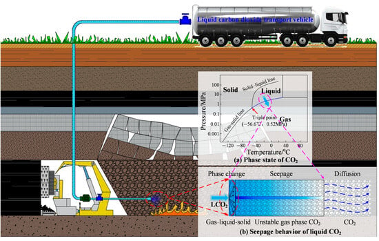
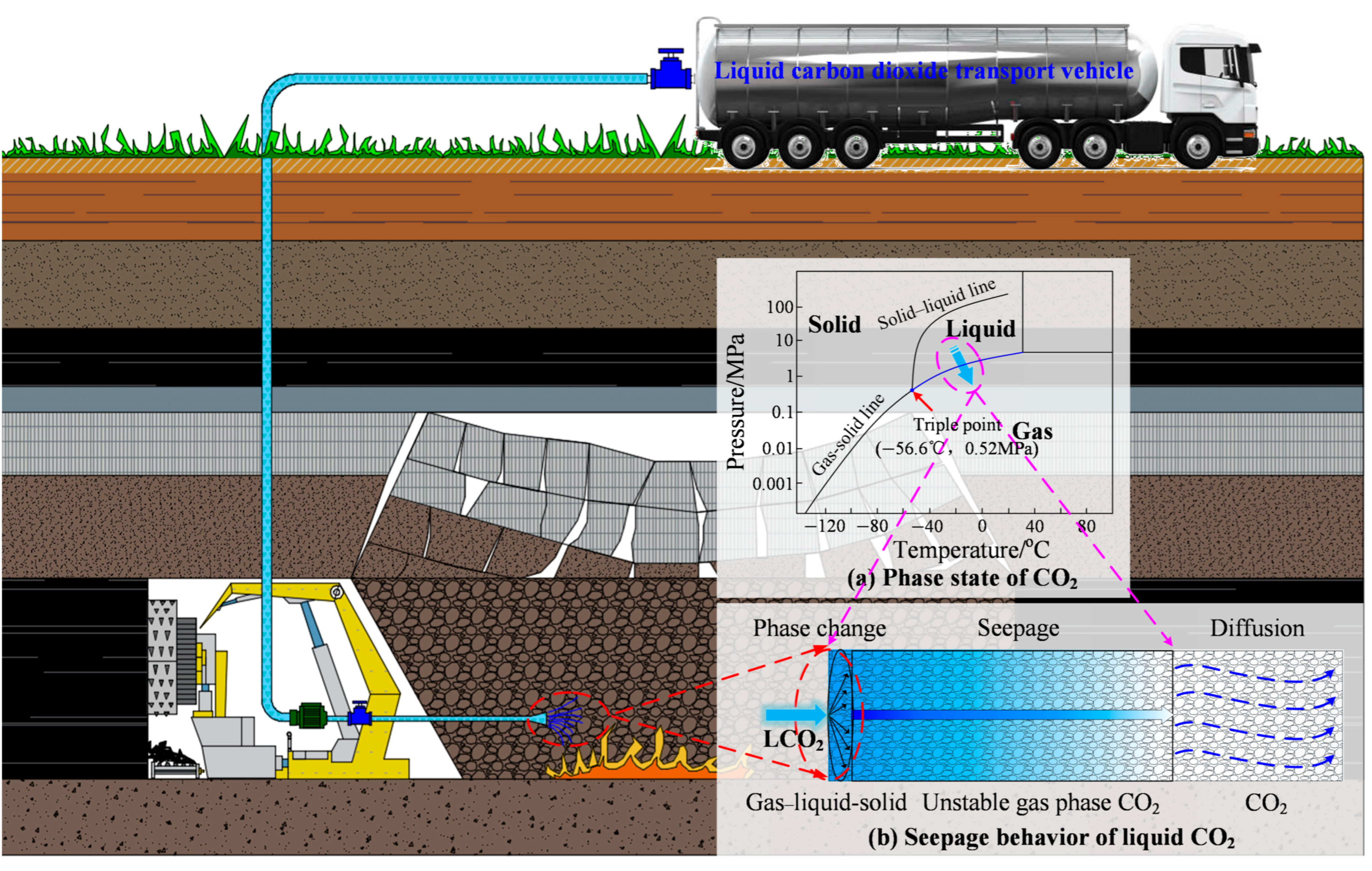
At present, the traditional fire prevention and extinguishing technologies, such as grouting, foam, and nitrogen injection in coal mines, have difficulty meeting the dual needs of rapid cooling and efficient oxygen insulation under complex conditions in the goaf [5,6,7]. In contrast, liquid CO2 (LCO2) has gradually become an important technical means to prevent and control CSC in the goaf due to its dual advantages of high efficiency oxygen insulation and endothermic cooling [8,9,10]. After LCO2 is injected into the goaf, due to the rapid phase change under depressurization, accompanied by volume expansion, temperature reduction and pressure fluctuation, the generated gaseous CO2 shows different characteristics of pressure, density and flow rate changing with time, and is called “unsteady gas phase CO2” (as shown in Figure 1) [11,12]. This unsteady seepage behavior with pressure and temperature fluctuations directly determines the inerting range and cooling effect of CO2 in the goaf [13]. However, currently, the seepage characteristics of unsteady gas-phase CO2 are still unclear, which leads to a lack of theoretical basis for the design of the flow rate and pressure of LCO2 injection. In field applications, this often causes problems such as excessive CO2 concentration at the working face or low fire extinguishing efficiency. Therefore, it is of great significance to reveal the seepage characteristics of unsteady gas-phase CO2 in broken coal particles for further understanding the seepage mechanism of LCO2 injection in goaf fire prevention and extinguishing processes.
Figure 1.
Generation and seepage mechanism of unsteady gas-phase CO2 in loose broken coal.
The seepage of unsteady gas-phase CO2 in loose broken coal particles is a complex mass transfer process of gas in porous media, and its behavior is controlled by the dual effects of the physical properties of the medium and the physical parameters of the gas [14,15,16]. At present, the research objects of gas seepage experiments in porous media mainly focus on two types: dense media (sandstone, granite) and loose media (loose broken coal) [17,18,19,20,21]. For dense media, Joseph et al. [22] revealed the synergistic mechanism of soil and gas properties with different pore structures on seepage through the GasCoM test device. Kudasik et al. [23] clarified the dynamic evolution of permeability, porosity, and pore size distribution of tight rocks such as sandstone and granite by using a small-scale rock permeability test device. Zhang et al. [24] reviewed the compaction and seepage characteristics of broken coal and rock masses and highlighted the effects of particle size, stress conditions, temperature, and pore-structure evolution on permeability. Chen et al. [25] conducted triaxial compression–permeability tests under different CO2 pressures and demonstrated that CO2 pressure significantly affects the evolution of coal permeability and internal fracture development. For loose media, Liu et al. [26] carried out steady-state seepage tests on broken rocks with five different particle sizes using air as fluid and obtained the relationship between non-Darcy permeability parameters and void fraction and particle size by binary fitting. Yu et al. [10] revealed the phase transition-diffusion coupling mechanism of LCO2 in broken coal by the combination of experiment and simulation.
In addition, the seepage equation is an important means to describe the seepage behavior of gas in porous media, in which Darcy’s law lays a theoretical foundation [27,28,29,30]. Zhao et al. [31] investigated the particle-size effect on seepage in loose coal and established particle-size-dependent models for permeability and the non-Darcy factor, identifying approximately 3 mm as a critical particle size for seepage behavior. Hao et al. [32] analyzed the seepage law of gas desorption in heterogeneous coal through experiments and established a seepage model of gas desorption in heterogeneous coal. Luo et al. [33] constructed and verified the applicability of the nonlinear seepage equation through the seepage test of fractured coal under different stress and gas pressure gradients. Zhao et al. [34] investigated the seepage characteristics of loose coal at the mesoscale and revealed a nonlinear relationship between particle size and permeability, together with a transition from Darcy to non-Darcy flow. Chen et al. [35] deduced the seepage equation considering the non-Darcy effect for low-permeability reservoirs and one-dimensional radial flow problems, respectively.
Although many advancements have been made in the study of gas seepage in porous media, the existing research mostly focuses on steady-state and homogeneous conditions, lacking the exploration of the seepage characteristics of unsteady gas-phase CO2 in loose broken coal and the construction of corresponding seepage equations. As a result, it restricts the prediction of the effect of unsteady gas-phase CO2 on the prevention and control of CSC in the goaf. In this study, an experimental system was designed independently to carry out the unsteady CO2 seepage test of broken coal with different particle sizes. Furthermore, the relationship between flow velocity and pressure drop and the influence of particle size were analyzed. In addition, an equation for the seepage of unsteady CO2 in loose broken coal was constructed. The research results have significant theoretical and engineering significance for predicting the application effect of LCO2 prevention and control technology for CSC in the goaf.
2. Experimental Methods
2.1. Sample Preparation
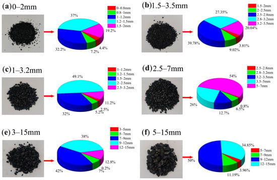
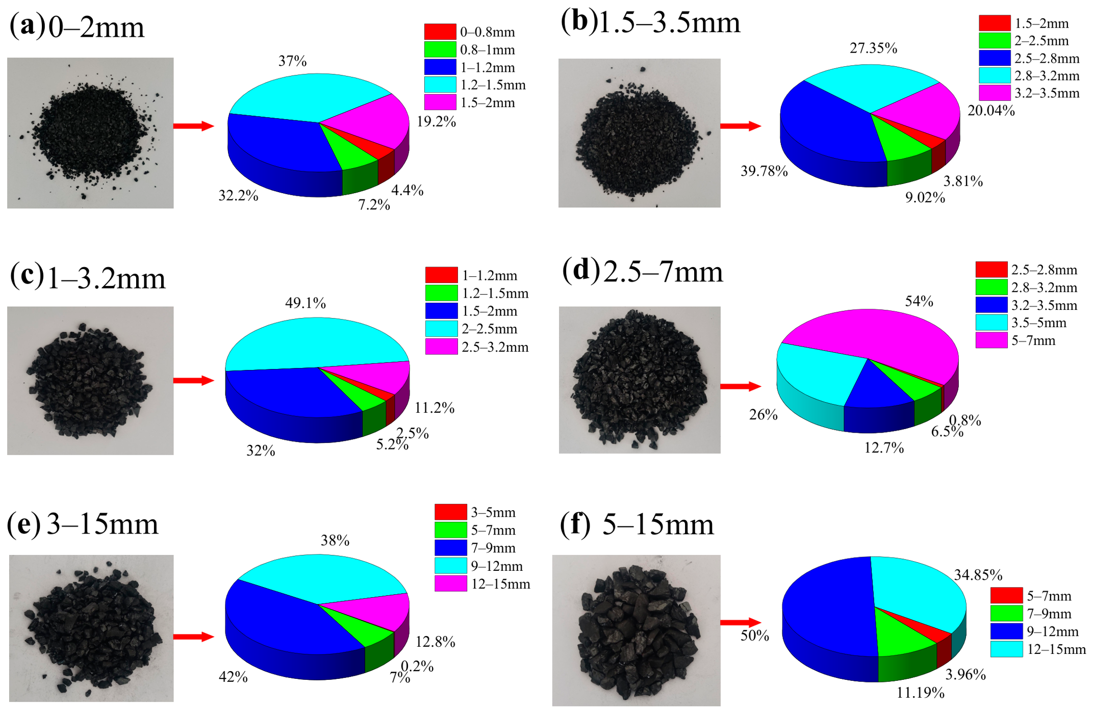
Coal samples were collected from different locations at the No. 10 coal seam working face of Xin’an Coal Mine in Shuangyashan, Heilongjiang Province, China. The collected samples comprised six groups with different degrees of crushing and were used to investigate the seepage characteristics of unsteady gas-phase CO2 in loose broken coal. These samples were sieved using standard sieves with apertures ranging from 0.8 mm to 15 mm, specifically including sizes of 0.8 mm, 1 mm, 1.2 mm, 1.5 mm, 2 mm, 2.5 mm, 2.8 mm, 3.2 mm, 5 mm, 7 mm, 9 mm, 12 mm, and 15 mm. Subsequently, the selected samples were weighed to determine their particle size distribution and acquire the fundamental physical parameters for each of the six coal samples, as shown in Figure 2 and Table 1.
Figure 2.
Coal sample and particle size distribution. (a) –2 mm; (b) 1.5–3.5 mm; (c) 1–3.2 mm; (d) 2.5–7 mm; (e) 3–15 mm; (f) 5–15 mm.
Table 1.
Physical parameters of coal samples.
2.2. Experimental Apparatus
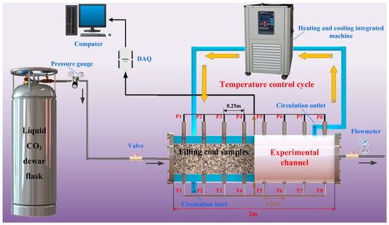
To simulate the seepage process of unsteady gas-phase CO2 formed by phase change after liquid CO2 is injected into the goaf, a seepage experiment system is built (Figure 3). The system is mainly composed of a LCO2 Dewar bottle, test container, heating and cooling equipment, temperature and pressure measurement unit, data acquisition system and pipeline valve. LCO2 is stored in a 175 L Dewar with an initial pressure of 2.3 MPa and a temperature of −14.8 °C. The test vessel is a double-layer stainless steel cylinder with a length of 2 m and an inner diameter of 0.2 m. The inner cavity is filled with loose and broken coal samples. The outer layer is connected with a temperature control medium. Both ends are insulated and sealed with flanges, and gas inlet and outlet are set. The temperature control medium adopts the down-in and up-out mode, which is controlled by the heating and cooling circulator, and the temperature control range is −40–250 °C. Eight groups of temperature and pressure measuring points (T1~T8, P1~P8) are arranged at an equal distance of 0.25 m from the injection end along the axial flow direction of CO2. CO2 is injected from the inlet, passing through P1~P8 (T1~T8) in turn along the axial direction and discharged from the outlet. The temperature and pressure signals of each measuring point and the pipeline flowmeter signal are synchronously connected to the data acquisition system to realize the real-time acquisition of temperature, pressure and flow parameters under the same working conditions. The accuracy of the pressure sensor is ±0.5% FS and the resolution is 1 Pa. The accuracy of the temperature sensor is ±0.5 °C and the resolution is 0.1 °C. The accuracy of the flowmeter is ±1.0% FS and the resolution is 0.1 L·min−1. Measurements are repeated three times for each flow condition, and the experimental results are averaged.
Figure 3.
Experimental apparatus for LCO2 injection.
The volumetric flow rate of CO2 measured by the flowmeter is converted into the apparent seepage velocity according to the cross-sectional area of the cylindrical test vessel, as shown in Equation (1).
where u is the apparent seepage velocity, cm·s−1; Q is the volumetric flow rate of CO2, m3·h−1; and r is the inner radius of the test vessel, m. The factor 3600 converts h to s, and the factor 100 converts m·s−1 to cm·s−1.
The seepage pressure gradient calculation formula [36] is:
In the formula, P1 and P2 are the inlet and outlet pressures of the container, Pa; L is the container length, m.
2.3. Experimental Conditions and Steps
In the seepage experiment, the CO2 pressure regulating valve on the pipeline and the heating and cooling integrated machine are used to adjust the unsteady gas-phase CO2, and different seepage flow rates are set by adjusting the opening of the outlet valve. The experimental conditions are shown in Table 2. The physical parameters of CO2 in different gas phases are calculated according to the physical parameter equation, Equation (3) [37], of CO2. The results are shown in Table 3.
Table 2.
Seepage experimental conditions.
Table 3.
Physical parameters of different unsteady gas-phase CO2.
In the formula, P is pressure, MPa; T is the thermodynamic temperature, K; ρ is density, kg·m−3; R is an ideal gas constant, 8.314 kJ·(mol·K)−1; and B0, A0, C0, a, b, c, and γ are material characteristic parameters.
The detailed procedure of the experiment is outlined as follows:
- (1)
- Before the experiment, replace the corresponding measuring instruments to check the air tightness of each measuring instrument, acquisition system, and pipeline.
- (2)
- Use the natural stacking method to fill the coal samples with the corresponding particle size. After filling, measure the height and mass of the bed, and calculate the bulk density and porosity. Then open the acquisition device and open the gas-phase outlet of the Dewar bottle.
- (3)
- Close the valve at the back end of the test vessel, adjust the pressure-reducing valve, stabilize the pressure in the pipe to the corresponding value, open the heating and cooling integrated machine to adjust the temperature in the pipe, and obtain an unsteady gas-phase CO2.
- (4)
- Record P1-P8 and flow data, open the back-end valve to stabilize the flowmeter to a certain value, and close the valve after 10 s.
- (5)
- According to the set flow rate, repeat 15 sets of pressure difference data under different flow rates.
- (6)
- Replace coal samples under other working conditions and prepare unsteady gas-phase CO2 to open the next set of experiments.
3. Experimental Results and Discussion
3.1. Analyze the Relationship Between Flow Velocity and Pressure Difference
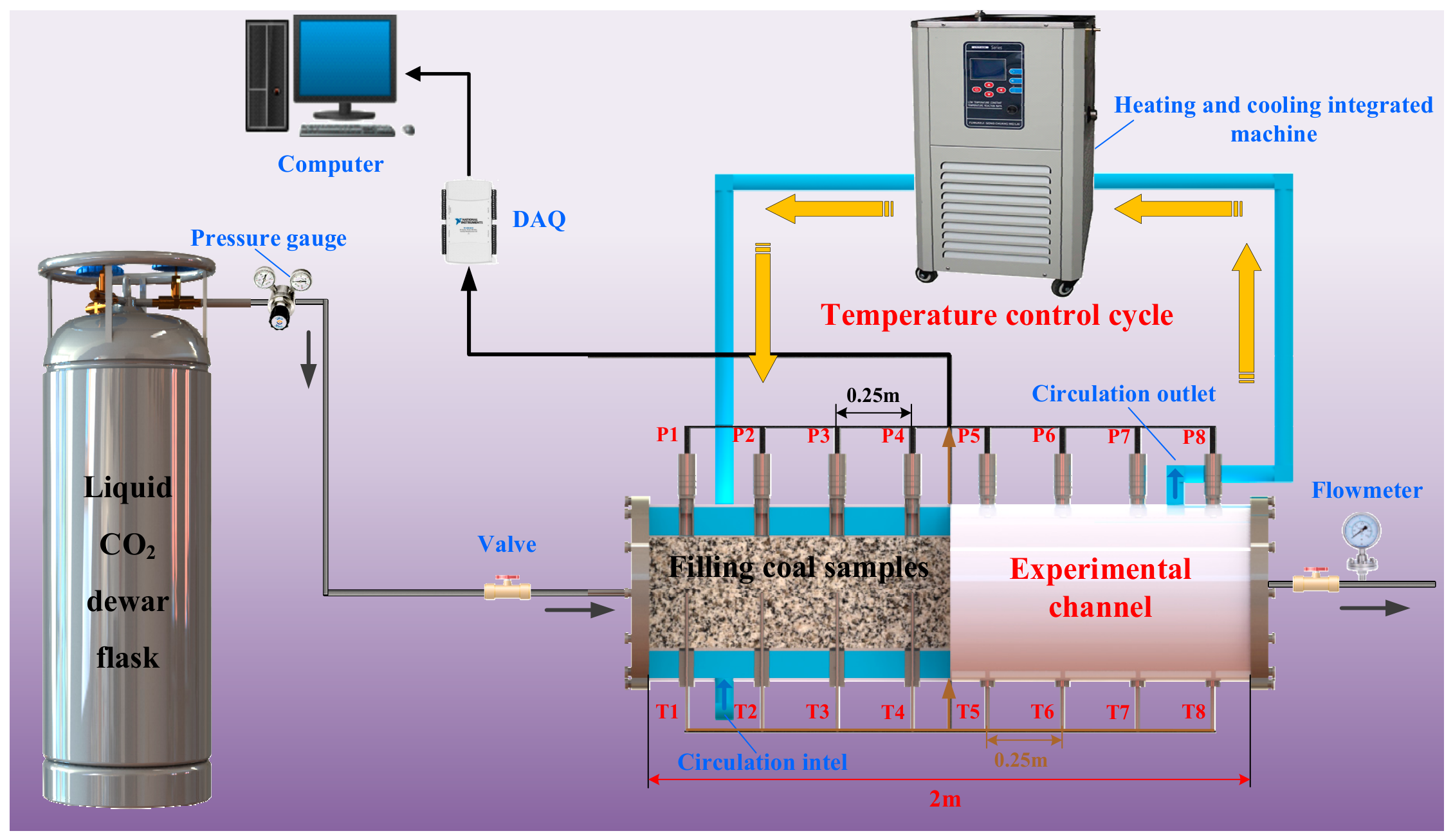
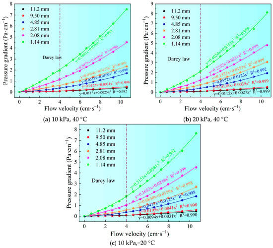
As can be seen from Figure 4, under the same flow velocity, the smaller the particle size of the crushed coal in the three groups of unsteady gas-phase CO2, the greater the corresponding pressure gradient. This is because the reduction in particle size leads to a decrease in the void-ratio between loose broken coal particles and a narrowing of the void channels, thereby increasing the seepage resistance of unsteady gas-phase CO2. By comparing Figure 4a–c, it is found that the three groups of unsteady gas-phase CO2 show a linear relationship when the flow velocity is lower than 4 cm·s−1, and their seepage behaviors all conform to Darcy’s law. When the flow velocity exceeds 4 cm·s−1, the increase in pressure gradient is significantly greater than that of seepage velocity, the seepage relationship deviates from linearity, and the seepage state transitions from Darcy seepage to non-Darcy seepage. In addition, the goodness of fit R2 of the flow velocity and pressure difference of the three groups of unsteady gas-phase CO2 under each particle size condition is greater than 0.99, indicating a high correlation between the two.
Figure 4.
The relationship curve between the flow velocity of unsteady gas-phase CO2 and the pressure gradient. (a) 10 kPa, 40 °C; (b) 20 kPa, 40 °C; (c) 10 kPa, −20 °C.
3.2. Analysis of Variation in Permeability Coefficient
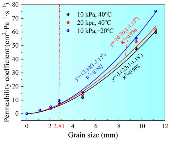
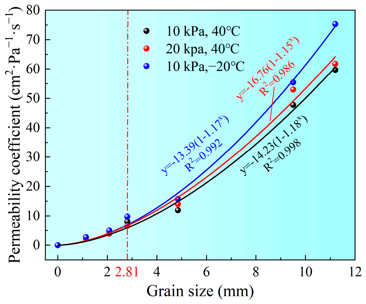
We quantitatively characterize the permeability of unsteady gas-phase CO2 in the loose broken coal. By intercepting the linear relationship data of flow velocity and pressure difference under each working condition in Figure 4, the permeability coefficient of unsteady gas-phase CO2 in loose broken coal under unit pressure gradient and unit flow velocity is calculated. The expression is shown in Equation (5) [25], and the calculation result is shown in Figure 5.
K = u/∇P
Figure 5.
Permeability coefficients of different unsteady gas-phase CO2 at different particle sizes.
In the formula, u is the flow velocity, cm·s−1; ▽P is the pressure gradient, Pa·cm−1.
It can be seen from Figure 5 that in the loose broken coal with a particle size less than 2.81 mm, the permeability coefficient (K) of the three kinds of unsteady gas-phase CO2 shows a relatively gentle upward trend, but its growth rate is relatively slow. However, when the particle size of the loose broken coal exceeds 2.81 mm, the K shows an accelerated upward trend. This change is primarily due to the increase in the particle size of the loose broken coal, which increases the void fraction between the particles and enlarges the effective seepage channels. According to the classical permeability theory for granular beds proposed by Carman [38], permeability is closely related to porosity and particle size. Therefore, increases in void fraction and particle size enhance the permeability of unsteady gas-phase CO2 through the loose, broken coal. In addition, it is also found that the permeation ability of three groups of unsteady gas-phase CO2 is different. Under the same particle size conditions, the permeability coefficient of unsteady gas-phase CO2 at (10 kPa, −20 °C) is the largest, followed by that at (20 kPa, 40 °C), and the smallest at (10 kPa, 40 °C).
3.3. Analysis of the Change in Seepage State
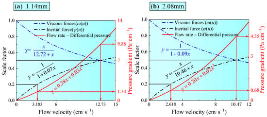
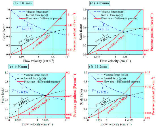
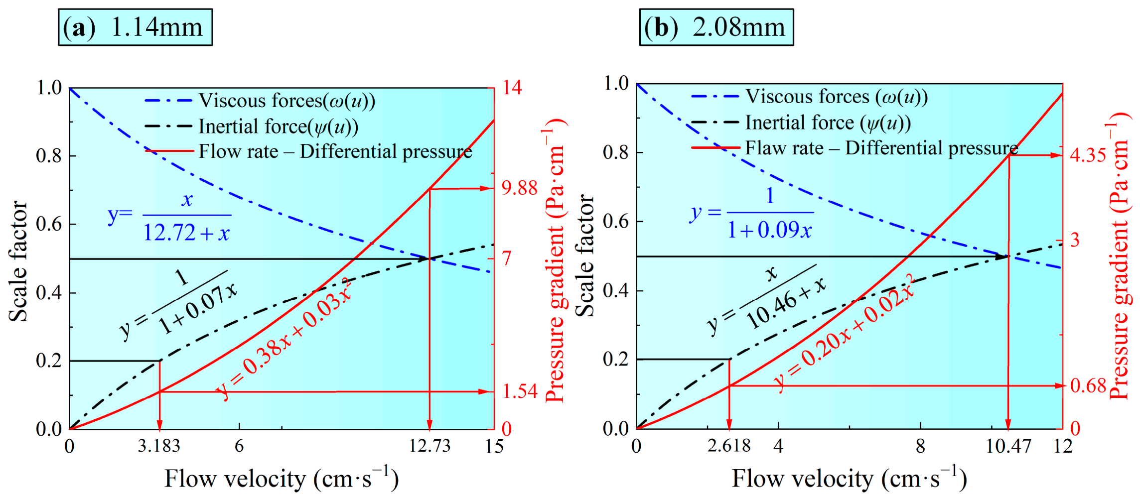
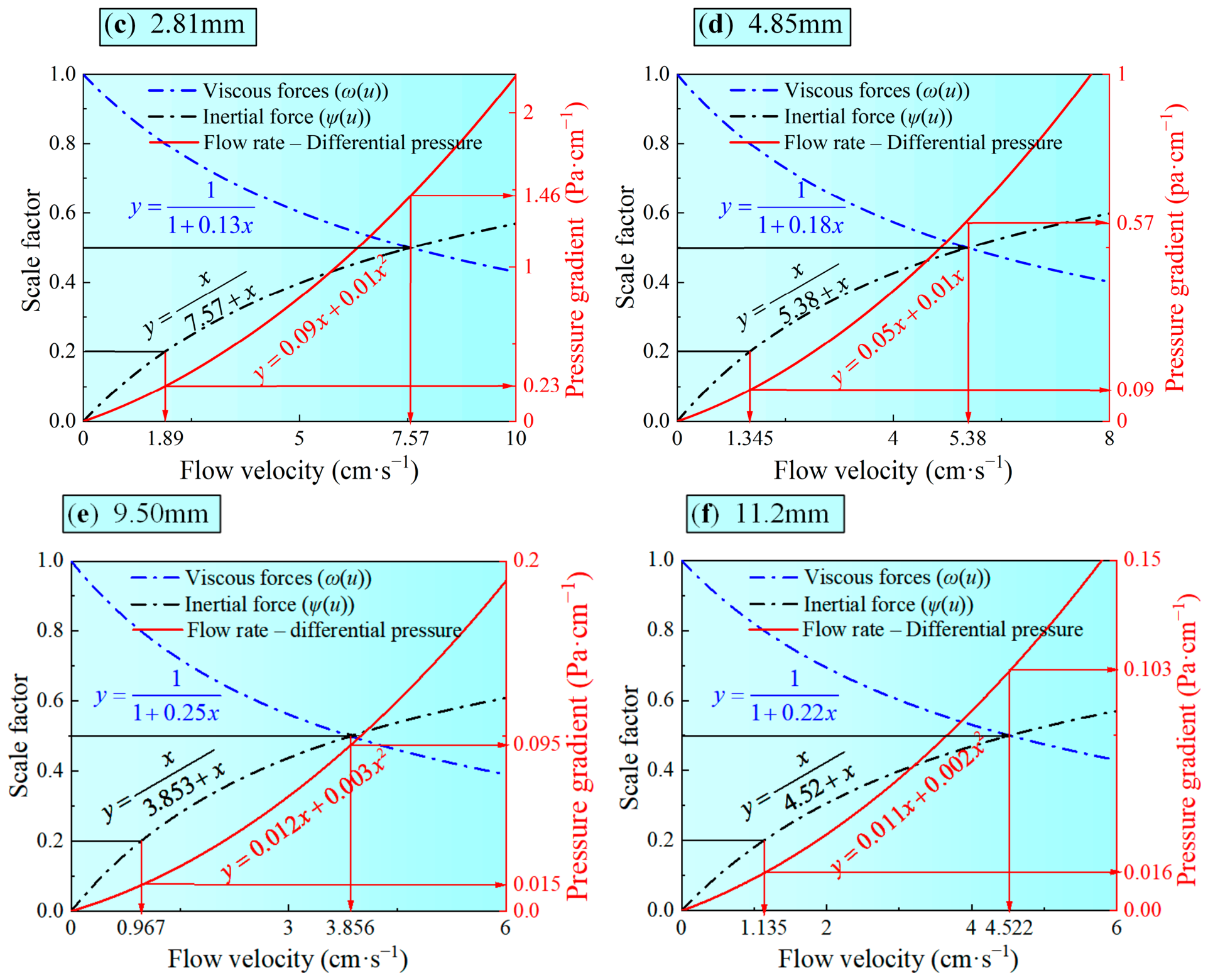
To analyze the change law of seepage state of unsteady gas-phase CO2 under different particle sizes, taking unsteady gas-phase CO2 at (10 kPa, 40 °C) as an example, the fitting equations in Figure 4a are processed according to Equations (5) and (6), and the curves of ω(u) and ψ(u) with flow velocity are drawn respectively, as shown in Figure 6.
Figure 6.
Values of ω(u) and ψ(u) and corresponding pressure gradients for different flow velocities at unsteady gas-phase CO2 (10 kPa, 40 °C). (a) 1.14 mm; (b) 2.08 mm; (c) 2.81 mm; (d) 4.85 mm; (e) 9.50 mm; (f) 11.2 mm.
The separation of viscous and inertial contributions is consistent with the classical Ergun-type description of flow through packed beds, in which the pressure drop is expressed as the combined effect of linear viscous resistance and nonlinear inertial resistance [39,40].
In the formula, ω(u) denotes the proportion of viscous force on the seepage state during the seepage process; ψ(u) denotes the proportion of inertial force on the seepage state during the seepage process; and a and b are the fitting coefficients in the flow velocity–pressure difference fitting equation, respectively.
The Reynolds number calculation formula is:
In the formula, Re is the Reynolds number; d is the characteristic length of loose broken coal, m.
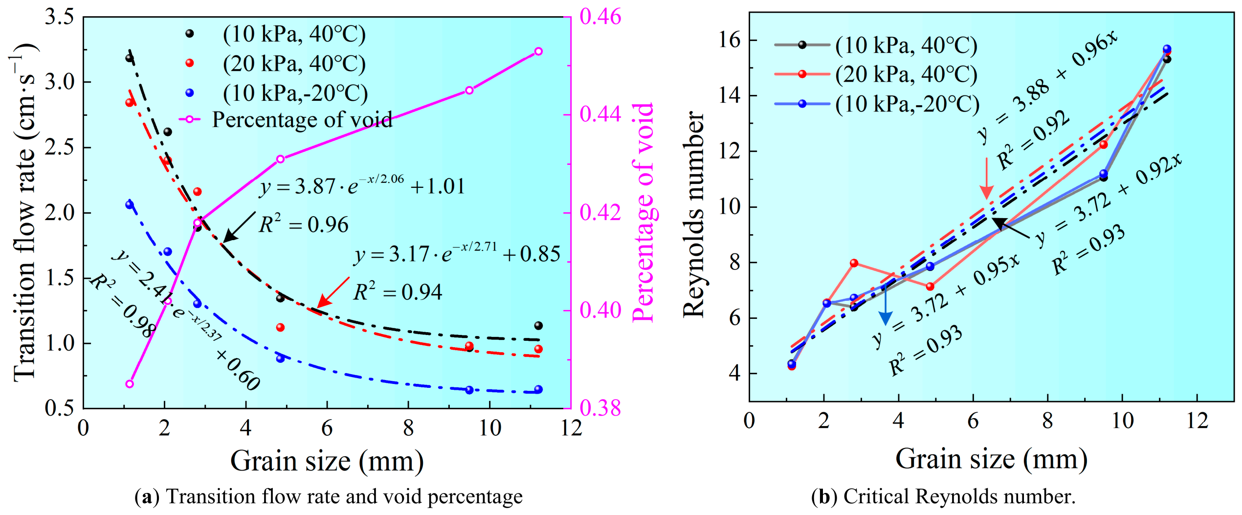
From Figure 6, it can be seen that with the increase in flow velocity, the value of ψ(u) increases, the value of ω(u) decreases, and the non-Darcy seepage under the influence of inertial force is more obvious. In similar practical applications, when the proportion of inertial force reaches 19.56%, the influence of the non-Darcy term cannot be ignored [31]. Therefore, ψ(u) = 0.2 is used as the boundary value. Previous studies on nonlinear flow in granular porous media have shown that particle-size distribution significantly affects nonlinear flow behavior and flow-regime transition [41]. When the proportion of inertial force is less than 0.2, the seepage state is considered to be Darcy seepage, and the flow velocity in the corresponding state is the transition velocity of the seepage state. At the same time, the critical Reynolds number (Re) under the corresponding transition velocity is calculated by Equation (7). With the increase in the particle size of the loose broken coal, the flow velocity of the seepage state from Darcy seepage to non-Darcy seepage gradually decreases, and the corresponding seepage pressure gradient also gradually decreases, while the critical Reynolds number increases with the increase in the particle size. This indicates that although ψ(u) = 0.2 is adopted as a unified threshold, the corresponding transition velocity remains dependent on particle size. The corresponding transition velocity (Vμ) and the critical Re of the three unsteady gas-phase CO2 are calculated as shown in Table 4.
Table 4.
Flow velocity and Reynolds number of unsteady gas-phase CO2 under different particle sizes.
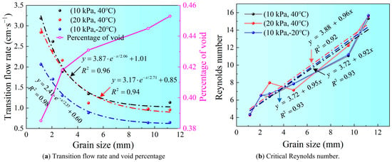
It can be found from Figure 7 that as the particle size of the coal sample increases, the transition velocity decreases rapidly. When the particle size increases to a certain extent, the downward trend of the seepage state transition velocity tends to be stable. This is because after the particle size increases to a certain extent, the change in the void fraction in the loose broken coal is only related to the accumulation mode of the coal sample, and the change in the particle size has a decreasing effect on the transition of the seepage state. In addition, the different unsteady gas-phase CO2 transition velocities are also different, which is due to the physical parameters of the unsteady gas-phase CO2 resulting in different percolation resistance within the loose broken coal.
Figure 7.
Transition velocity of unsteady gas-phase CO2 under percolation, and critical Reynolds number versus particle size. (a) Transition flow rate and void percentage; (b) Critical Reynolds number.
3.4. Determination of the Seepage Equation
Under the condition of direct injection of LCO2, the flow velocity of unsteady gas-phase CO2 is extremely fast due to phase-change expansion and jet drive, and its seepage in loose broken coal belongs to non-Darcy seepage. For high-velocity flow in porous media, inertial effects become non-negligible, and Darcy–Forchheimer-type models are commonly used to describe post-Darcy flow behavior [39,40]. Therefore, the non-Darcy seepage equation proposed by Forchheimer is adopted.
In the formula, β is the non-Darcy factor, m−1; ρ is the fluid density, kg·m−3.
Because of the phase change of L CO2 into unsteady gas-phase CO2 after injection into the goaf, its physical parameters change during the seepage process, so the compressibility of CO2 cannot be ignored. The continuous equation for compressible gas seepage is as follows [42].
ρAV = Qm
In the formula, Qm is the mass flow rate of gas, kg·s−1.
In this experiment, unsteady gas-phase CO2 was used as the test fluid. In many experiments, the gas pressure and temperature in the tube change little in a short time, so it can be regarded as an ideal gas. The ideal gas state equation is as follows [43].
In the formula, V is the volume of the ideal gas, m3; n is the amount of gas substance, mol; T is the thermodynamic temperature of the ideal gas, K; and R is an ideal gas constant, 8.314 J/(mol·K)−1.
Combined with Equations (8)–(10), we get
letting
For the given flow in the seepage channel, Qm is a constant, so Equation (11) can be expressed as:
The integral can be obtained.
Experimental boundary conditions: x = 0, P = P1; when x = L, P = P2. Then the integral constants c1 and c2 can be determined.
Substituting c1 into Equation (12), the one-dimensional seepage equation of gas can be obtained.
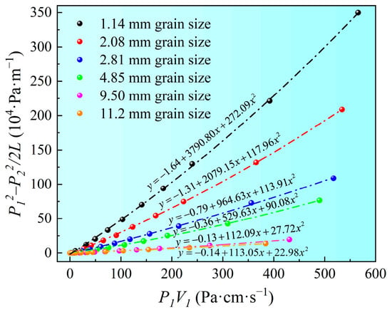
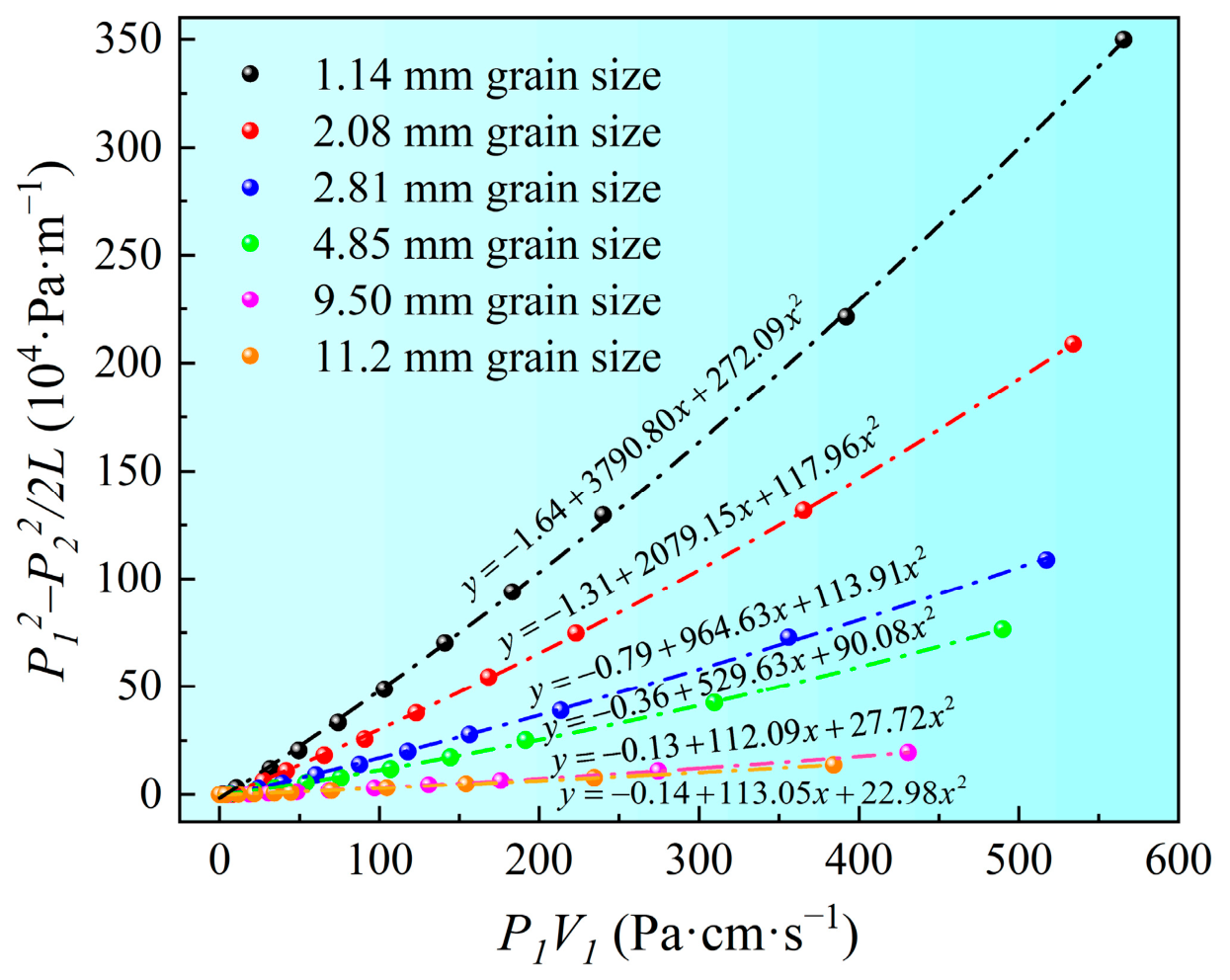
To determine the permeability k and the non-Darcy factor β in the seepage equation, n = P1V1, , , , and bring these into Equation (17).
J = in + jn2
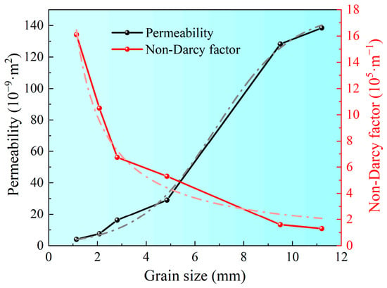
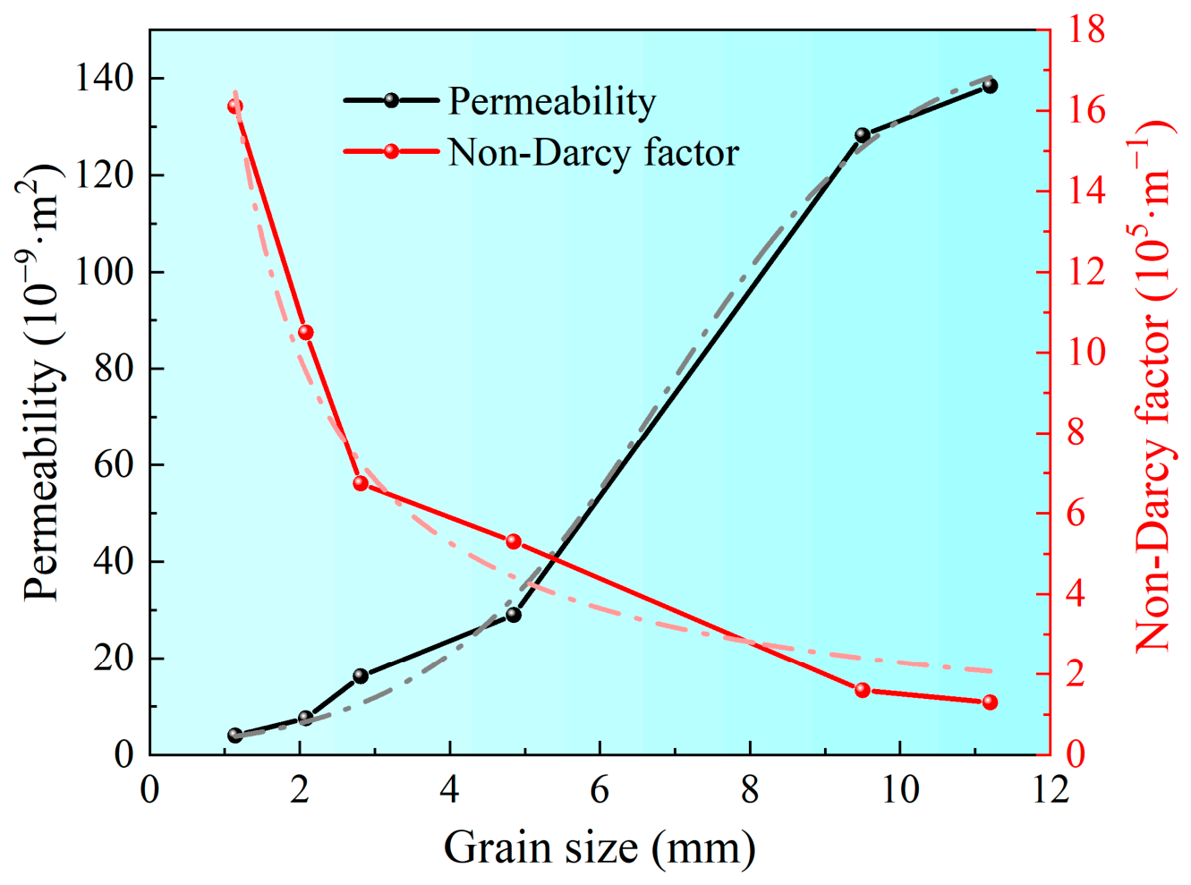
For each group of samples, according to the corresponding P1, P2, and V1 of several groups measured by the test, i and j are fitted, and then the permeability (k) and non-Darcy factor (β) are calculated. Since k and β are not affected by fluid properties, only unsteady gas-phase CO2 at (10 kPa, 40 °C) is used for subsequent analysis. The fitted permeability k and non-Darcy factor β can be used to characterize the viscous and inertial seepage resistance, respectively, which is consistent with the physical interpretation of Ergun/Forchheimer coefficients [40]. The corresponding calculated values and fitting curves are shown in Figure 8 and Table 5. Based on the above calculation results, the k and β of unsteady gas-phase CO2 (10 kPa, 40 °C) at different particle sizes are obtained, as shown in Figure 9.
Figure 8.
Fitting curve for i, j values.
Table 5.
Results of permeability and inertia coefficient calculations.
Figure 9.
Permeability, non-Darcy factor prediction curve.
By fitting the calculated values in Figure 9, the mathematical expressions of k, β, and particle size can be obtained as shown in Equations (19) and (20).
where x is the particle size of the loose broken coal, mm; k is the permeability, m2; and β is the non-Darcy factor, m−1.
β = (18.53 × x−0.9) × 106 m−1
Combined with Equation (8), Equations (19) and (20), the theoretical equations for the unsteady gas-phase CO2 seepage characteristics within the loose broken coal, can be obtained for the influence of the particle size of the loose broken coal on the permeability as well as the non-Darcy factor, as shown in Equation (21).
In Equation (21), k and β are substituted in SI units, where k is in m2 and β is in m−1. Therefore, the pressure gradient calculated by Equation (21) has the unit of Pa·m−1, ensuring dimensional consistency on both sides of the equation.
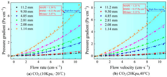
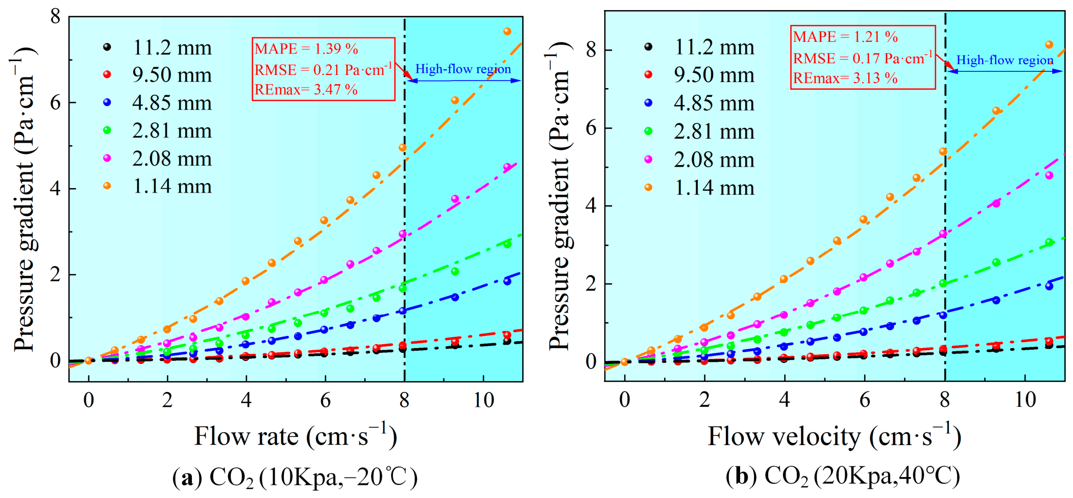
To verify the accuracy of the established equations, the actual physical parameters of the other two groups of unsteady gas-phase CO2 are brought into Equation (21), while the experimental results are used to compare the models, and the comparison results are shown in Figure 10.
Figure 10.
Comparison between model results and experimental test results. (a) CO2 (10 kPa, −20 °C); (b) CO2 (20 kPa, 40 °C).
As shown in Figure 10, the calculated pressure gradients generally agree with the experimental measurements over the investigated velocity range. To quantitatively evaluate the model performance at relatively high flow velocities, the mean absolute percentage error (MAPE), root mean square error (RMSE), and maximum relative error (REmax) are calculated for the data at v ≥ 8 cm·s−1. Under the conditions of 10 kPa and −20 °C, the MAPE, RMSE, and REmax are 1.39%, 0.21 Pa·cm−1, and 3.47%, respectively, while the corresponding values under 20 kPa and 40 °C are 1.21%, 0.17 Pa·cm−1, and 3.13%. Although the deviation increases slightly with increasing flow velocity, the quantitative error analysis indicates that the model maintains acceptable predictive accuracy in the high-velocity region. Therefore, the proposed seepage equation is capable of describing the relationship between flow velocity and pressure gradient for gas-phase CO2 flowing through loose broken coal within the investigated experimental range.
4. Conclusions
In this study, the seepage characteristics of unsteady gas-phase CO2 in loose broken coal were studied, the key factors affecting the flow behavior were revealed, and the theoretical prediction model of seepage was established. The main conclusions are as follows:
- (1)
- Unsteady gas-phase CO2 exhibits nonlinear seepage in loose broken coal. When the flow velocity is lower than 4 cm·s−1, its seepage behavior conforms to Darcy’s law and shows a linear relationship. When the flow velocity exceeds 4 cm·s−1, the increase in pressure gradient is significantly greater than the flow velocity, and the seepage state changes from Darcy flow to non-Darcy flow.
- (2)
- The permeability coefficient increases exponentially with the particle size of coal. When the particle size of the coal sample is less than 2.81 mm, the increase of the permeability coefficient (K) is gentle. When the particle size of the coal sample exceeded 2.81 mm, the K showed an accelerating upward trend. Under the same particle size conditions, the ranking of the K of unsteady gas-phase CO2 is (10 kPa, −20 °C) > (20 kPa, 40 °C) > (10 kPa, 40 °C), indicating that low temperature and low pressure phase change CO2 is more conducive to seepage expansion and inerting cooling.
- (3)
- As the particle size increases, the Reynolds number gradually increases, while the transition velocity gradually decreases. When the particle size is greater than 11.2 mm, the downward trend of the transition velocity tends to level off, indicating that the influence of particle size change on seepage transition is weakened under the condition of large particle size. The upper limit of LCO2 injection velocity can be deduced according to the transition velocity. When the particle size is too large, the CO2 inerting range and cooling effect are ensured by adjusting the injection pressure, flow rate and injection mode.
- (4)
- Based on the Darcy–Forchheimer equation, considering the influence of the real physical parameters of CO2 and the particle size of coal samples, the seepage theoretical model of unsteady gas-phase CO2 in loose coal is constructed, and the verification accuracy is good. It can provide theoretical support for the design of LCO2 injection flow rate, pressure and temperature under the condition of broken coal particle size in goaf.
Further research perspectives: The results of this paper can provide preliminary experimental basis and theoretical reference for the parameter design of LCO2 injection in goaf. However, due to the limitation of experimental conditions, the verification is only completed in the same device, the same coal source and the same particle size range, and no independent coal source, different pressure ranges, on-site scale geometry or external data sets have been used. Therefore, the on-site prediction ability and practical guiding significance of the model still need to be further verified under more extensive conditions.
Author Contributions
X.Z.: Conceptualization, methodology, investigation, and writing—original draft preparation; Z.Z.: supervision, writing—review and editing, project administration, and funding acquisition; S.Y.: data curation, formal analysis, and investigation; F.Z.: investigation, visualization, and validation; Z.Y.: Supervision, writing—review and editing, and funding acquisition. All authors have read and agreed to the published version of the manuscript.
Funding
This research was funded by the National Natural Science Foundation of China (No. 52474249).
Data Availability Statement
All original data for this research are included in the article.
Conflicts of Interest
The authors declare no conflict of interest.
Abbreviations
The following abbreviations are used in this manuscript:
| CSC | Coal Spontaneous Combustion |
| LCO2 | Liquid Carbon Dioxide |
References
- Onifade, M.; Genc, B. A review of research on spontaneous combustion of coal. Int. J. Min. Sci. Technol. 2020, 30, 303–311. [Google Scholar] [CrossRef] [Scilit]
- Chen, J.; Lu, Y.; Tang, G.; Yang, Y.; Shao, S.; Ding, Y. Research and prevention of upper remaining coal spontaneous combustion induced by air leakage in multi-inclination regenerated roof: A case study in the Luwa coal mine, China. Energy 2023, 275, 127484. [Google Scholar] [CrossRef] [Scilit]
- Ray, S.; Singh, R. Recent developments and practices to control fire in undergound coal mines. Fire Technol. 2007, 43, 285–300. [Google Scholar] [CrossRef] [Scilit]
- Song, Z.; Kuenzer, C. Coal fires in China over the last decade: A comprehensive review. Int. J. Coal Geol. 2014, 133, 72–99. [Google Scholar] [CrossRef] [Scilit]
- Song, H.; Wei, F.; Cheng, F.; Duan, D.; Wu, H.; Gao, Y.; Li, W. Formulation determination and performance study of high-volume fly ash-based grouting fire extinguishing materials. J. Build. Eng. 2024, 88, 109194. [Google Scholar] [CrossRef] [Scilit]
- Sheng, Y.; Li, X.; Fan, X.; Ma, L.; Li, Y.; Lu, Y. Highly stable protein foam used to prevent coal mine fire. Fuel 2026, 418, 138755. [Google Scholar] [CrossRef] [Scilit]
- Hu, L.; Zhu, H.; Wang, J.; Qu, B.; Liao, Q.; Tao, R.; Zhang, Z. Research and application of continuous and precise nitrogen injection fire extinguishing technology in coal mines. Miner. Eng. 2024, 215, 108801. [Google Scholar] [CrossRef] [Scilit]
- Guo, L.; Du, H.; Cui, X.; Zhang, J.; Wang, K.; Wu, J.; Guo, H. Research progress and prospects of CO2 fire prevention and extinguishing technology in mine goafs. Thermochim. Acta 2025, 747, 179977. [Google Scholar] [CrossRef] [Scilit]
- Yu, Z.; Huang, D.; Wen, H.; Zhang, Z.; Li, R. Modeling and parametric investigation on suppression of coal self-heating in mined-out area by liquid carbon dioxide injection. Fuel 2024, 373, 132382. [Google Scholar] [CrossRef] [Scilit]
- Yu, Z.; Yang, S.; Wen, H.; Deng, J. Experimental investigation of the impact of liquid carbon dioxide injection on temperature in pulverized coal. Greenh. Gases Sci. Technol. 2020, 10, 147–159. [Google Scholar] [CrossRef] [Scilit]
- Wang, K.; Du, Y.; Zhai, X.; Deng, J.; Gao, P. Migration and cooling characteristics of low-temperature gaseous CO2 in high-temperature loose coal. Energy 2024, 301, 131741. [Google Scholar] [CrossRef] [Scilit]
- Rezk, M.G.; Foroozesh, J.; Abdulrahman, A.; Gholinezhad, J. CO2 diffusion and dispersion in porous media: Review of advances in experimental measurements and mathematical models. Energy Fuels 2021, 36, 133–155. [Google Scholar] [CrossRef] [Scilit]
- Seyyedi, M.; Giwelli, A.; White, C.; Esteban, L.; Verrall, M.; Clennell, B. Effects of geochemical reactions on multi-phase flow in porous media during CO2 injection. Fuel 2020, 269, 117421. [Google Scholar] [CrossRef] [Scilit]
- Pourbakhtiar, A.; Poulsen, T.; Faghihinia, M.; Papadikis, K.; Wilkinson, S. Relating wind-induced gas transport in porous media to wind speed and medium characteristics. J. Pet. Sci. Eng. 2020, 194, 107550. [Google Scholar] [CrossRef] [Scilit]
- Chai, D.; Yang, G.; Fan, Z.; Li, X. Gas transport in shale matrix coupling multilayer adsorption and pore confinement effect. Chem. Eng. J. 2019, 370, 1534–1549. [Google Scholar] [CrossRef] [Scilit]
- Nian, J.; He, C.; Zhao, B.; Lv, X.; Deng, C. Asymmetric development of overburden fracture and gas migration law for a goaf of entry formed by roof cutting. Energy Sci. Eng. 2024, 12, 4070–4089. [Google Scholar] [CrossRef] [Scilit]
- Fauria, K.E.; Rempel, A.W. Gas invasion into water-saturated, unconsolidated porous media: Implications for gas hydrate reservoirs. Earth Planet. Sci. Lett. 2011, 312, 188–193. [Google Scholar] [CrossRef] [Scilit]
- Ho, M.T.; Zhu, L.; Wu, L.; Wang, P.; Guo, Z.; Ma, J.; Zhang, Y. Pore-scale simulations of rarefied gas flows in ultra-tight porous media. Fuel 2019, 249, 341–351. [Google Scholar] [CrossRef] [Scilit]
- Akilu, S.; Padmanabhan, E.; Sun, Z. A review of transport mechanisms and models for unconventional tight shale gas reservoir systems. Int. J. Heat Mass Transf. 2021, 175, 121125. [Google Scholar] [CrossRef] [Scilit]
- Fang, X.; Tan, B.; Wang, H.; Wang, F.; Li, T.; Wan, B.; Xu, C.; Qi, Q. Experimental study on the displacement effect and inerting differences of inert gas in loose broken coal. Energy 2024, 289, 130102. [Google Scholar] [CrossRef] [Scilit]
- Wu, T.; Wang, Q.; Wang, S. An apparent gas permeability model for real gas flow in fractured porous media with roughened surfaces. Polymers 2021, 13, 1937. [Google Scholar] [CrossRef] [Scilit] [PubMed]
- Joseph, J.; Kuntikana, G.; Singh, D. Investigations on gas permeability in porous media. J. Nat. Gas Sci. Eng. 2019, 64, 81–92. [Google Scholar] [CrossRef] [Scilit]
- Kudasik, M.; Anioł, Ł.; Gajda, A.; Pajdak, A. Influence of confining pressure on permeability and structural properties of selected sedimentary, igneous, and metamorphic rocks. Bull. Eng. Geol. Environ. 2023, 82, 455. [Google Scholar] [CrossRef] [Scilit]
- Zhang, C.; Chen, Y.; Ren, Z.; Wang, F. Compaction and seepage characteristics of broken coal and rock masses in coal mining: A review in laboratory tests. Rock Mech. Bull. 2024, 3, 100102. [Google Scholar] [CrossRef] [Scilit]
- Chen, L.; Wang, L.; Zhang, Y.; Jin, K.; Wu, Y.; Yang, Z.; Liao, Z. Triaxial-mechanical and permeability properties of coal body under varying CO2 pressures. Sci. Total Environ. 2024, 946, 174261. [Google Scholar] [CrossRef] [Scilit] [PubMed]
- Liu, W.; Zhou, Y.; Chu, X.; Qin, Y.; Hu, J. Effects of seepage behaviors on coal spontaneous combustion in longwall gobs: An investigation between Darcy and non-Darcy seepage. Fuel 2022, 322, 124126. [Google Scholar] [CrossRef] [Scilit]
- Jouybari, N.F.; Lundström, T.S. Investigation of post-Darcy flow in thin porous media. Transp. Porous Media 2021, 138, 157–184. [Google Scholar] [CrossRef] [Scilit]
- Teng, T.; Xue, Y.; Zhang, C. Modeling and simulation on heat-injection enhanced coal seam gas recovery with experimentally validated non-Darcy gas flow. J. Pet. Sci. Eng. 2019, 177, 734–744. [Google Scholar] [CrossRef] [Scilit]
- Zolotukhin, A.; Gayubov, A. Semi-analytical approach to modeling Forchheimer flow in porous media at meso- and macroscales. Transp. Porous Media 2021, 136, 715–741. [Google Scholar] [CrossRef] [Scilit]
- Farmani, Z.; Azin, R.; Fatehi, R.; Escrochi, M. Analysis of Pre-Darcy flow for different liquids and gases. J. Pet. Sci. Eng. 2018, 168, 17–31. [Google Scholar] [CrossRef] [Scilit]
- Zhao, J.; Yang, F.; Song, J.; Lu, S.; Hang, G.; Deng, J.; Zhang, Y. Study on normal temperature seepage model of loose coal under particle size effect. Mater. Chem. Phys. 2026, 349, 131797. [Google Scholar] [CrossRef] [Scilit]
- Hao, Z.; Jian, K.; Peng, S.; Xu, J.; Xu, L. A mechanical model and numerical method for gas seepage analysis considering gas desorption in heterogeneous coal. Nat. Resour. Res. 2022, 31, 2699–2714. [Google Scholar] [CrossRef] [Scilit]
- Luo, Y.; Zhu, Y.; Huang, F. An experimental study on the seepage characteristics of rough fractures in coal under stress loading. Processes 2024, 12, 757. [Google Scholar] [CrossRef] [Scilit]
- Zhao, J.; Yang, X.; Song, J.; Liu, W.; Dai, R.; Deng, J.; Zhang, Y. Study on the determination of the mesoscale critical range of loose coal body and its seepage characteristics. Fuel 2026, 405, 136766. [Google Scholar] [CrossRef] [Scilit]
- Chen, X.; Li, Y.; Jiang, Y.; Liu, Y.; Zhang, T. Theoretical research on gas seepage in the formations surrounding bedded gas storage salt cavern. Pet. Sci. 2022, 19, 1766–1778. [Google Scholar] [CrossRef] [Scilit]
- Majdalani, S.; Guinot, V. Solute transport in heterogeneous model porous media under different flow rates: Experimental and modelling study. J. Hydrol. 2023, 616, 128790. [Google Scholar] [CrossRef] [Scilit]
- Yadav, P.K.; Srivastava, P. Impact of porous material and slip condition on the MHD flow of immiscible Couple stress-Newtonian fluids through an inclined channel: Head loss and pressure difference. Chin. J. Phys. 2024, 89, 1198–1221. [Google Scholar] [CrossRef] [Scilit]
- Carman, P.C. Fluid flow through granular beds. Trans. Inst. Chem. Eng. 1937, 15, 150–166. [Google Scholar]
- Ergun, S. Fluid flow through packed columns. Chem. Eng. Prog. 1952, 48, 89–94. [Google Scholar]
- Macdonald, I.F.; El-Sayed, M.S.; Mow, K.; Dullien, F.A.L. Flow through porous media—The Ergun equation revisited. Ind. Eng. Chem. Fundam. 1979, 18, 199–208. [Google Scholar] [CrossRef] [Scilit]
- Van Lopik, J.H.; Snoeijers, R.; Van Dooren, T.C.G.W.; Raoof, A.; Schotting, R.J. The effect of grain size distribution on nonlinear flow behavior in sandy porous media. Transp. Porous Media 2017, 120, 37–66. [Google Scholar] [CrossRef] [Scilit]
- Guo, Z.; Wang, L.P.; Qi, Y. Discrete unified gas kinetic scheme for continuum compressible flows. Phys. Rev. E 2023, 107, 025304. [Google Scholar] [CrossRef] [Scilit] [PubMed]
- Du, Y.; Zhu, J.; Han, X.; Fu, M.; Li, M.; Shen, Y. Gas state equation and flow mechanism of gas–liquid two-phase flow in airlift pump system. Phys. Fluids 2024, 36, 055142. [Google Scholar] [CrossRef] [Scilit]

Disclaimer/Publisher’s Note: The statements, opinions and data contained in all publications are solely those of the individual author(s) and contributor(s) and not of MDPI and/or the editor(s). MDPI and/or the editor(s) disclaim responsibility for any injury to people or property resulting from any ideas, methods, instructions or products referred to in the content. |
© 2026 by the authors. Licensee MDPI, Basel, Switzerland. This article is an open access article distributed under the terms and conditions of the Creative Commons Attribution (CC BY) license.