


Abstract
Product design constitutes an iterative process centered on user requirements. In this process, user requirements are collected, interpreted by designers and transformed into design objectives, which are then refined through solution generation and evaluation to yield the final product; this is typically an iterative human–computer interaction process. The intent understanding process converts vague user requirements into standardized expressions for designers. For complex products, existing intent understanding methods are hindered by excessive reliance on experience, lack of iterative mechanisms, and insufficient identification of critical performance attributes. To address these limitations, this paper proposes a computational methodology for element-based intent understanding, positioned as a foundational layer for future human–computer collaborative design systems. The concept of “elements” is introduced at three levels: function, performance, and structure—to aid in the standardization of design objectives. Relationships among elements are defined and used to construct design objectives, establishing a transformation model from elements to objectives. An iterative reconstruction method for element-objective transformation under design iteration is further proposed. The feasibility of this method is empirically validated via a reactor fuel-handling case study.
1. Introduction
With the integration of knowledge and technology, the complexity and scale of modern advanced engineering systems continue to grow [1]. High-complexity products composed of subsystems from diverse disciplinary domains are increasingly emerging: such as spacecraft, aircraft, automobiles, robots, and CNC machine tools [2]. The conceptual design of such products demands substantial design freedom to realize geometrically sophisticated, multi-material, and functionally optimized architectures [3] and also introduces unique challenges regarding manufacturability constraints and complicated interdependencies among design, manufacturing process, and material properties [4]. These complex products involve multiple disciplines including mechanical, electronic, control, and systems engineering, and are characterized by numerous modules and systems. Their performance requirements place heightened demands on reliability, safety, and other critical attributes [5].
Product design represents a knowledge-driven iterative process wherein user requirements serve as inputs and design solutions as outputs [6]. The intent understanding process bridges user requirements with design objectives; however, requirement information is typically highly ambiguous and unstructured [7]. Designers must integrate disparate design information to reduce abstraction and uncertainty, transforming it into clear, actionable design objectives expressed as combinations of function and performance.
The transformation from user requirements to design objectives is a process of moving from ambiguity to precision and determinacy; this is typically an iterative human–computer interaction process. For this reason, much research has predefined design objectives and established mappings from needs to objectives, yet deeper investigation into the understanding and translation of user requirements remains necessary. Moreover, current studies predominantly adopt a single-iteration perspective rather than an iterative one, lacking corrective and feedback mechanisms when design deviations require re-execution of the intent understanding process. In the design of complex products, reliability is one of the core performance attributes of concern [8], often determined collectively by multiple functions, structures, and systems [9]. Moreover, current intent understanding approaches predominantly lack interactive feedback mechanisms, limiting effective human–computer collaboration when design deviations require iterative correction. Therefore, the influence of reliability should be considered throughout the design process [10], and its implications should be captured and extracted during the intent understanding phase and then efficiently integrated with other related requirements.
Since user requirements span multiple dimensions—including function, performance, and structure—and existing theories already provide robust descriptions of functional (e.g., functional bases [11]) and structural characteristics [12] in design, this paper integrates these theoretical foundations to propose the concept of “elements” as an intermediate variable between needs and design objectives. Elements serve as constraints on design objectives, introduce additional transformation steps in the intent understanding process, enhance its effectiveness, broaden the coverage of design objectives, and establish executable procedures and methods for iterative design.
2. Related Research
2.1. Methods for Transforming User Requirements into Design Objectives
The Kano model [13] is a key tool for analyzing user requirements, categorizing them into basic, expected, attractive, indifferent, and reverse needs. It reveals the nonlinear relationship between product performance and customer satisfaction, enabling qualitative analysis of user requirements. This method remains widely used across various fields to this day; for example, Yang et al. [14] developed a requirements analysis method based on BERT-TCBAD Kano and conducted user needs analysis for new energy vehicles, and Xia et al. [15] proposed a hybrid interface design method for a virtual reality driverless vehicle system by combining an A-KANO model and system usability scale. The Analytic Hierarchy Process (AHP) is another widely used method, which decomposes indicators into hierarchical levels and incorporates consistency checks to assess statistical error, effectively supporting user requirements analysis [16]. Building on this, the Analytic Network Process (ANP) has been developed and applied in certain contexts [17]. These methods are often combined with other novel approaches in practical applications; for example, Liu et al. [18] established an innovative model by integrating the Kano model, the Analytic Hierarchy Process, and the Technique for Order of Preference by Similarity to Ideal Solution (TOPSIS), and Qian et al. [19] established a Kano-QFD-PUGH-based method in the architecture field. Additionally, Feng et al. [20] integrated cognition into digital twins and transformed requirements into necessary functions and structures during the design phase. Dou et al. [21] applied a fuzzy Kano model to evaluate product attribute satisfaction from both customer perception and competitor performance perspectives, using an optimized gray relational model to identify dynamic user requirements. Horan et al. [22] employed a dynamic function-quality-deployment approach rooted in sustainable development to model user expectations for sustainable design and integrated these requirements into the design process. He et al. [23] utilized a fuzzy Kano model to design user questionnaires and modeled the uncertainty and diversity of customer evaluations using binary linguistic variables.
With the rise in internet technologies and advancements in big data and artificial intelligence, online data mining using deep learning or a large language model (LLM) has become a critical approach for user requirements analysis. Wei et al. [24] proposed a framework based on a large language model to extract users’ insights into the priority of product attributes, Liu et al. [25] proposed a novel method for user requirement mining based on BERTopic and RoBERTa, combining the strengths of topic modeling and sentiment analysis to provide a more comprehensive analysis of user needs, Cui et al. [26] proposed an integrated requirement elicitation, sentiment analysis, classification, importance calculation and mixed requirement evolution method, Zhang et al. [27] proposed a method utilizing online comments and operational data to identify user requirements and their influencing factors, and Zheng et al. [28] proposed MEI-Pro, a novel progressive interaction and adaptive weight fusion-based multimodal joint understanding of emotion and intent framework to improve the effect of emotion and intent joint understanding. Li et al. [29] introduced a sentiment engineering and machine learning-based opinion mining method to extract user requirements from online reviews, validating results with five machine learning algorithms: support vector machines, support vector regression, classification and regression trees, multilayer perceptrons, and ridge regression.
While these methods effectively map user requirements to predefined design objectives, their outcomes vary significantly with the design task and are entirely dependent on the designer’s prior assumptions. Therefore, they often fail to comprehensively cover all required design aspects and lack standardized expression formats.
2.2. Methods for Transforming User Requirements into Design Features or Parameters
Classic methods such as interviews and questionnaires are instrumental in capturing user requirements. For specific products, these approaches can further refine design parameters in subsequent stages. Lo et al. [30] employed a qualitative research method, utilizing semistructured interviews and task observations, to investigate the perspectives and perceptions of individuals regarding user needs for hand rehabilitation devices at home. Quality Function Deployment (QFD) is a widely used method for directly mapping user requirements to product parameters [31]. QFD integrates user requirements with technical characteristics through the “house of quality” and further propagates them into subsequent design stages. This model relies on expert judgment and enables the transformation of needs into precisely defined design objectives. Building on QFD, Zhang et al. [32] developed a Quality-Function-Knowledge-Deployment (QFKD) model tailored to the distinct knowledge requirements of conceptual design, structural design, detailed design, and production planning stages, linking stage-specific needs with product knowledge. Guo et al. [33] conducted requirement mining based on a product enterprise competitiveness model and the Existence–Performance model, integrating TQCSE and 5W2H1E methods to construct a requirement transformation model that transitions engineering features into process features. Jiang et al. [34] used QFD and axiomatic design in the function-knowledge model to realize the mapping from user requirements to product functions.
These methods still depend heavily on experts to predefine design objectives and lack dynamic adaptability.
Beyond QFD-based approaches, many researchers have employed alternative methods to convert user requirements into design features or parameters. Kim et al. [35] selected ten technological domains and employed BERTopic and thematic analysis to identify user needs. Arbelaez et al. [36] developed a software platform under a 3D scanning environment to analyze and evaluate user preferences for color. Jiang et al. [37] established performance constraint indicators through user requirements, and the VIKOR algorithm is utilized to associate these clusters with performance constraint indicators, revealing the discrepancies between performance and structural space. Afshari et al. [38] applied modern control engineering techniques to translate changes in user requirements into impacts on product cost and development time. Simpson et al. [39] integrated market segmentation grids, generational diversity indices, design structure matrices, commonality indices, mathematical modeling and optimization, and multidimensional data visualization tools to select appropriate methods for different types of user requirements, facilitating the translation of needs into the design process.
These approaches directly map needs to specific parameters in downstream design steps, but require tuning through a set of hyper-parameters and remain heavily reliant on designer experience. Furthermore, their limited integration with interactive computational platforms restricts dynamic human–computer co-evolution during iterative design processes. When design iterations occur and needs or solutions change, there is a lack of mechanisms to dynamically adjust mappings. Therefore, their application within iterative design processes still requires further investigation.
2.3. Research Gap
Existing approaches to design intent understanding in complex product conceptual design have made significant progress, yet several critical limitations remain unaddressed.
QFD-based methods excel at translating user requirements into technical characteristics through the house of quality matrix. However, QFD treats requirements as static inputs and lacks mechanisms to capture the intrinsic relationships among design elements, which are essential for understanding how changes in one requirement propagate through the design space.
Kano-based approaches categorize user requirements into basic, expected, attractive, indifferent, and reverse needs, providing a framework for requirement prioritization. However, these methods focus primarily on classifying and ranking requirements based on customer satisfaction rather than establishing structured relationships among design elements, and they lack mechanisms to model how changes in one requirement propagate through the functional, performance, and structural dimensions during iterative design.
Knowledge-driven methods leverage expert experience and rule bases to guide design decisions. These approaches, however, are highly dependent on expert availability and struggle to generalize across different product domains, particularly when dealing with the implicit and evolving relationships among design elements.
A critical observation across these existing methods is that they often operate at two extremes: either at the abstract level of user requirements (as in QFD) or at the concrete level of design solutions (as in CAD-based design). This creates a significant gap in the design process—there is a lack of an intermediate representation that can bridge the semantic gap between “what the user wants” and “how the designer should design.”
Current approaches attempt to map requirements directly to design solutions without an explicit intermediate layer that captures the evolving understanding of design intent. As a result, when requirements change or become refined during the design process, the rationale behind design decisions becomes difficult to trace, and the propagation of requirement changes through the design space cannot be systematically managed.
To address this gap, this paper proposes the concept of “element” as an intermediate construct that sits between raw user requirements and final design objectives. Elements are not introduced as an independent research target; rather, they emerge as a necessary intermediate representation to make design intent traceable, operable, and computable. By decomposing user requirements into hierarchical function–performance–structure (F-P-S) elements, the proposed approach provides a granular layer where intrinsic relationships among design components can be explicitly modeled and reasoned about, thereby enabling systematic intent understanding before design solutions are generated.
Furthermore, this work is explicitly framed as a computational methodology rather than a fully implemented interactive system. The element-based approach establishes formal representations and algorithmic procedures that can serve as the intent understanding layer in future human–computer collaborative design frameworks.
3. The Intent Understanding Process
3.1. Problem Statement and Research Hypothesis
Based on the identified research gap, this paper addresses the following core research question: how can intrinsic relationships among hierarchical design elements be systematically modeled and utilized to support design intent understanding in complex product conceptual design?
This problem encompasses three sub-questions: P1: What intrinsic relationship types exist among function, performance, and structure elements in complex product design? P2: How can these relationships be formally represented in an ontology that supports computational reasoning? P3: How can the relationship model be applied to trace and articulate design objectives from hierarchical elements?
Research Hypothesis: An ontology-based intrinsic relationship model, encompassing seven fundamental relationship types (inclusion, semi-inclusion, confliction, semi-confliction, sequence, coexistence, and independence), enables systematic design objective articulation from hierarchical function–performance–structure elements in complex product conceptual design. This hypothesis posits that the explicit modeling of intrinsic relationships among design elements provides a more structured and traceable foundation for design intent understanding than approaches that treat elements as independent entities.
The method proposed in this paper is positioned at the front end of the conceptual design process, specifically targeting the intent understanding phase. It is important to clarify that this work does not encompass the entire conceptual design workflow; rather, it focuses on the critical transition from user requirements to structured design objectives.
The method takes user requirements as input, decomposes them into hierarchical F-P-S elements, establishes intrinsic relationships among these elements, and ultimately articulates structured design objectives. Once these design objectives are clearly defined, designers must still carry out subsequent conceptual design activities—including solution generation, embodiment design, and detailed design—based on these objectives.
In other words, the contribution of this paper lies in providing a systematic foundation for the intent understanding phase, ensuring that the design objectives derived from user requirements are well-structured, traceable, and consistent before designers proceed to the creative and generative stages of conceptual design.
3.2. Element Definition
As a constraint mechanism, elements encompass requirements related to product function, performance, structure, and derived costs incurred during the project [20]. Elements can be categorized into three types: function elements, performance elements, and feature elements. Function and performance elements may be interdependent, while feature elements are independent.
3.2.1. Function Elements
Function elements describe the various functions of a product, expressed using the concept of functional bases [11]. Building on the functional base model, Liu et al. [40] refined it by representing functions in the form “operational attribute + functional object,” where functional objects include energy, signals, and materials, and operational attributes consist of ten primary categories: movement, output, introduction, accumulation, combination, detection, regulation, separation, generation, and stabilization. Further decomposition yields 54 secondary and 251 tertiary categories, as defined in [31]. Function elements leverage the principles and definitions of functional bases to extract and articulate functional requirements from user requirements.
3.2.2. Performance Elements
Performance elements extend function elements by imposing constraints on functions as specified by user requirements. In addition to functional constraints, user expectations for overall product characteristics cannot be fully decomposed into discrete, deterministic combinations of individual functions; thus, performance elements must also capture user requirements regarding intrinsic product attributes. In constraining functions, performance elements include both qualitative and quantitative descriptions expressed in physical quantities. The base physical units include length, mass, time, electric current, temperature, amount of substance, and luminous intensity, from which derived quantities such as velocity, volume, frequency, and energy are defined. Regarding overall product attributes, performance elements also encode users’ implicit expectations—such as overall price or subjective experience. Since performance is directly tied to evaluation systems, it can be classified into three main types: technical, social, and economic. As user requirements often fail to precisely define performance, performance elements may be expressed either deterministically (e.g., “velocity > 10 m/s”) or fuzzily (e.g., “fast velocity”).
3.2.3. Feature Elements
Feature elements represent user requirements pertaining to product structure, with their attributes imposing specific constraints on physical configurations. Product features can be decomposed into structural, motion, constraint, and dynamic characteristics. Structural features include primary shape, key dimensions, and material properties. Motion features encompass kinematic (type, direction) and dynamic (continuity, linearity, reciprocation) properties. Constraint features include speed magnitude, number of motion actuators, gear ratio, degrees of freedom, motion direction, adjustability, and motion precision. Dynamic features include stiffness, inertia, vibration, load, natural frequency, and other related parameters.
3.3. Overall Process of Intent Understanding
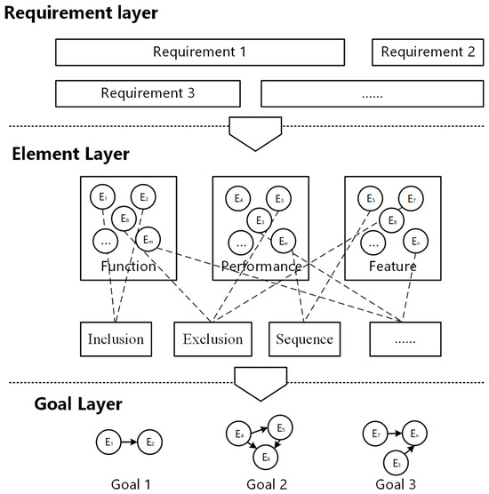
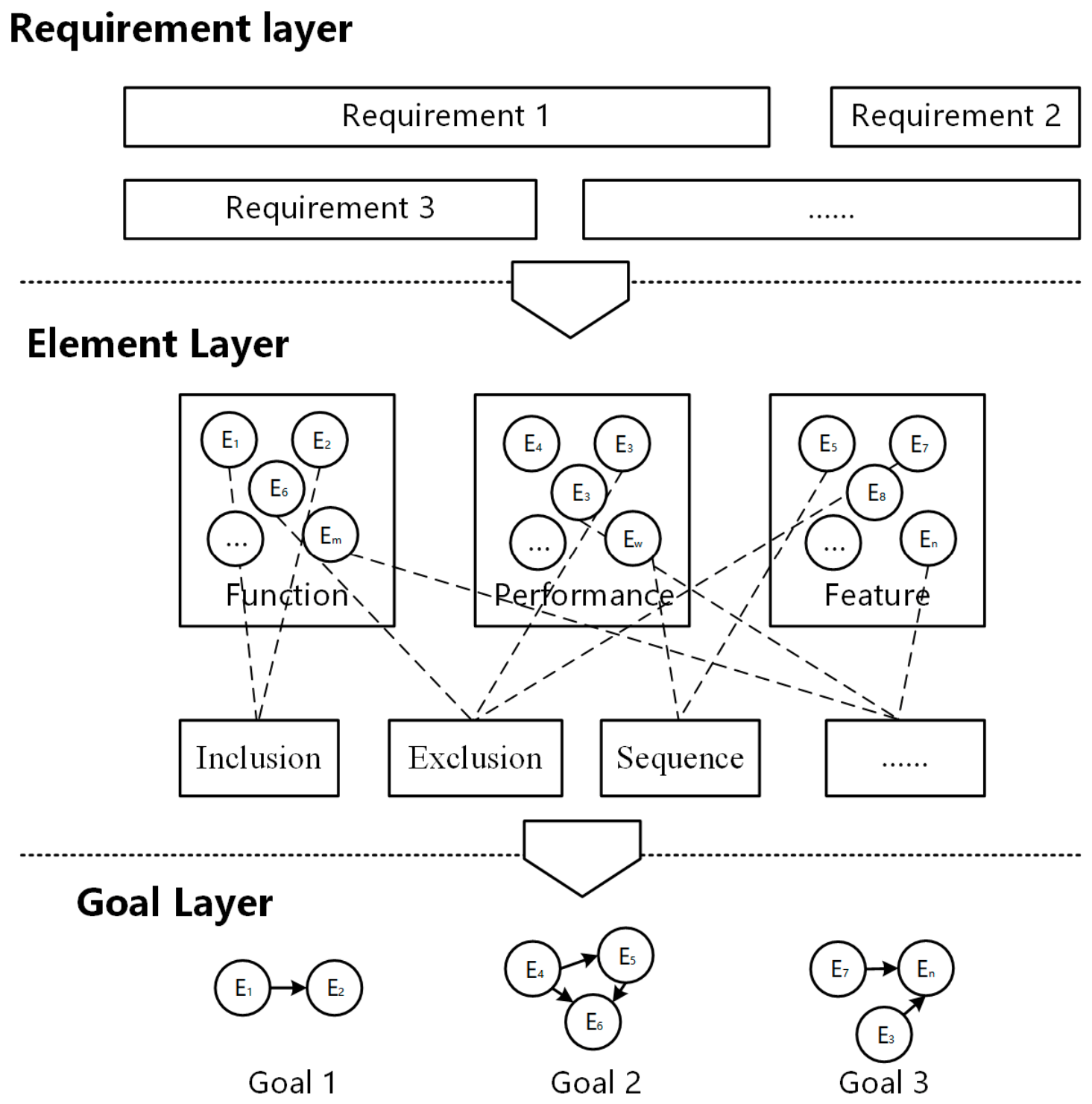
The intent understanding process is represented as a flowchart in Figure 1. Requirements are collected through various channels and organized. They are then decomposed into function, performance, and feature elements, which exhibit relationships such as inclusion, exclusion, and sequence. These relationships are systematically structured to form complete element chains, where each of which constitutes a distinct design objective.
Figure 1.
Schematic illustration of the overall workflow.
The process begins with the collection and organization of raw user requirements from multiple channels. These requirements are subsequently decomposed into hierarchical function, performance, and feature elements. Intrinsic ontological relationships among elements—including inclusion, semi-inclusion, confliction, semi-confliction, sequence, coexistence, and independence—are identified and formally structured to construct element chains. Each complete element chain is then articulated into a distinct, structured design objective, where are the elements.
3.4. The Transformation Process from Elements to Objectives
Elements are generated through the requirements decomposition process. However, design objectives cannot be directly formed from elements because there are various relationships between them. For instance, one element may conflict with another, making their simultaneous realization impossible; two elements may impose different constraints on the same function, feature, or performance.
An ontology represents a collection of concepts and relationships [41]. It serves as a formal knowledge representation suitable for human–computer collaborative systems. This framework expresses the relationships between different elements. During the element-to-objective transformation process, elements need to be combined into element chains based on ontological relationships, which are then further articulated into project objectives. The ontological relationships are shown in Table 1.
Table 1.
Relationships between elements.
Among all seven ontological relationships, inclusion, semi-inclusion, confliction, semi-confliction, and sequence can be superimposed—meaning multiple relationships may exist between elements. However, if elements have either an independent or coexistence relationship, they can only be in one of these two mutually exclusive states. For clarity, all relationships except independent are collectively termed “non-independent relationships”. The element relationship matrix () for a group of n elements is defined as
Here, represents the relationship between Element 1 and Element 2, encoded as an array. Since inclusion and sequence are directional, and may differ. For practicality, relationships are mapped to numeric codes (as shown in Table 2).
Table 2.
Numeric codes of element relationships.
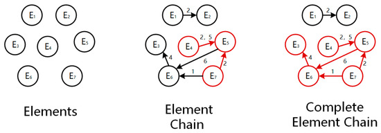
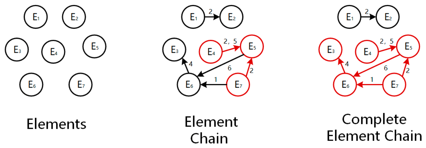
In a set of n elements (denoted as ), if every element has at least one non-independent relationship with another, forms an element chain (shown in red in Figure 2). Within a full set of elements (), if an element chain satisfies the following:
Figure 2.
Element chain and complete element chain.
All elements outside only have independent relationships with elements inside . Then is a complete element chain, representing the final design objective (as shown in Figure 2, highlighted in red). It can be expressed via a table.
4. Simplification and Reconstruction Process
4.1. Goal of Simplification and Reconstruction Process
On design iteration, design objectives are directly constructed from elements and their interrelationships. The relationships between elements create various connections. While these connections comprehensively describe design intent, excessively high relational density can cause design objectives to interfere with one another, making it difficult for designers to quickly identify core contradictions during iterative correction.
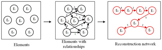
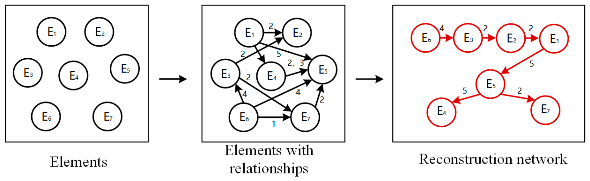
When design deviations are identified as primarily stemming from erroneous design objectives, a target correction process called reconstruction is initiated at the element level. This involves: reconstructing element relationships, decoupling interdependent elements, and rebuilding the relationship network (as shown in Figure 3). The core idea is to preserve the essential content of each element while transforming complex many-to-many relational networks into clear pairwise relationship pathways (shown in red in Figure 3), thereby significantly reducing complexity.
Figure 3.
Reconstruction process.
An element chain, composed of elements, relationships and specific values, reflects the interdependencies among design requirements. While the existing relationships constrain the element definitions, the high density of interconnections among multiple elements increases the complexity of design objective formulation, making it difficult for designers to identify the core logic of requirement fulfillment. The reconstruction process simplifies the chain by focusing on element content and establishing pairwise relationship pathways, significantly reducing complexity.
Though more information is contained before simplification, the original chain’s excessive relational complexity may hinder the realization of certain elements in design. While this simplification may lose some relational information, it enables clearer design objective expression by streamlining multiple elements and relationships into a simplified structure that starts from one element, incorporates all necessary elements, and minimizes overall relationship complexity, thereby optimizing design objectives and resolving objective errors during intent understanding.
4.2. Calcualtion Process
To support interactive decision-making during iteration, the simplification goal is to streamline the element chain into a sequential structure where each element maintains only its most essential relationships with adjacent elements [42]. The distance metrics assigned between element pairs serve as indicators of relationship complexity, with larger distances corresponding to more intricate interdependencies that require closer attention during simplification.
Through systematic analysis of these inter-element distances, the element chain can be reorganized into an ordered element array that preserves all critical design requirements while eliminating redundant relational complexity. This process consists of three main steps.
4.2.1. Simplification Objective
The simplification objective is to extract a sparse skeleton structure from the dense element relationship network, enabling designers to focus on the most essential interdependencies during iterative decision-making. The skeleton consists of two components: a primary chain that captures the backbone of design intent through sequentially connected elements and branch elements that attach to specific hub elements in the primary chain. Relationships not incorporated into the skeleton remain documented in the original requirement specification but are not directly expressed in the simplified structure. This approach preserves all design intent information while reducing cognitive load by highlighting only the most critical relational pathways.
4.2.2. Distance Assignment Rules
The assignment of distance values is governed by the principle that higher relationship complexity corresponds to larger distance indicators. The specific rules are as follows:
- (a)
- Inclusion: If the content of Element A is fully covered by Element B, only Element B needs to be retained in the simplified objective. The complexity of an inclusion relationship is assigned the maximum value, indicating that this relationship should be prioritized during simplification.
- (b)
- Semi-Inclusion: The assigned value ranges within (0,1). A larger value indicates a greater overlap between elements, meaning more redundant information needs to be preserved during simplification.
- (c)
- Confliction: The complexity of a conflict relationship is assigned a value of 1, indicating that the two elements are entirely incompatible and a trade-off must be made in the design.
- (d)
- Semi-Confliction: The assigned value ranges within (0,1). A smaller value indicates a higher degree of conflict, requiring priority handling during simplification.
- (e)
- Sequence: The complexity of a sequence relationship depends on the complexity of the constrained element. The higher the complexity of the element being constrained, the higher the complexity of the sequence relationship, and thus the larger the assigned value. The value ranges within (0,1), and the higher the element complexity, the larger the value.
- (f)
- Coexistence: The calculation method for coexistence relationships is the same as that for sequence relationships.
- (g)
- Independence: The distance between independent elements is defined as infinite, ensuring they are never placed adjacent in the simplified chain.
- (h)
- Skeleton Extraction Principle: After distance assignment, all non-independent relationships are sorted by their distance values in ascending order. The skeleton is constructed by progressively selecting relationships with the smallest distances, forming a primary chain that connects the maximum number of elements. Each element in the primary chain maintains adjacency with at most two other elements (one predecessor and one successor) to preserve the chain structure. When no further element can be appended to either end of the chain through a non-independent relationship, the primary chain extraction terminates.
- (i)
- Branch Recognition Criterion: Elements not incorporated into the primary chain are evaluated for branch potential. A candidate element is recognized as a branch if it maintains a non-independent relationship with exactly one element in the primary chain (termed the hub element), and has independent relationships (infinite distance) with all other elements in the primary chain. Such branch elements are attached to their hub element as supplementary nodes, preserving the essential relationship without forcing artificial adjacency among independent elements.
- (j)
- Implicit Relationship Preservation: Relationships that are neither included in the primary chain nor recognized as branch attachments remain documented in the original element relationship matrix. These relationships are not deleted but are implicitly preserved in the requirement specification. Designers can refer to the original matrix when detailed relational information is needed beyond the simplified skeleton.
4.2.3. Solution and Supplementary Verification
With the distance metrics defined, the element chain simplification proceeds through three stages: (1) primary chain extraction, (2) branch recognition, and (3) supplementary verification.
Stage 1: Primary Chain Extraction. All non-independent relationships are sorted by distance in ascending order. Starting from the relationship with the smallest distance, elements are progressively connected into a sequential chain. At each step, the relationship that extends the chain by one additional element with the smallest available distance is selected. The process continues until no further element can be appended to either end of the chain. The resulting primary chain represents the backbone of the simplified design objective.
Stage 2: Branch Recognition. Each element not in the primary chain is examined: if it has a non-independent relationship with exactly one element in the primary chain and independent relationships with all others, it is recognized as a branch attached to that hub element. If no branch elements are identified, this stage is skipped.
Stage 3: Supplementary Verification. The primary chain is verified to ensure all adjacent pairs have non-independent relationships. Each branch attachment is verified to ensure the branch element is independent of all primary chain elements except its hub. If any adjacent pair in the primary chain lacks a non-independent relationship, the chain is segmented at that point.
At this point, the element relationships are reconstructed, forming a new design objective.
5. Case Study
5.1. Design Background
Much of the equipment in the nuclear industry possesses high-safety, long-service-life and large-system characteristics, making them typical complex products. Fuel-handling machines are representative equipment in nuclear systems. During stable reactor operation, refueling is typically performed every 12–18 months for nuclear fuel with specific shapes at designated locations, usually replacing only part of the fuel assemblies in the core each time.
Existing refueling methods are typically performed during outage maintenance periods. This approach requires first shutting down the reactor and opening the pressure vessel. Overly frequent short maintenance cycles would significantly reduce reactor economy, while repeated pressure vessel openings and reactor start–stop operations also affect overall operational reliability. Reducing outage maintenance is an important direction for improving reactor economy. Against this background, the author and their team designed an internal reactor refueling device installed within the pressure vessel.
5.2. Complete Element Chain Construction
The intent understanding process takes user phase requirements as input and produces design objectives as output. For this design task, the initial phase requirements were:
Requirement 1: Avoids internal guide columns during movement;
Requirement 2: Minimizes the use of sensors and complex electronic components to ensure safety;
Requirement 3: Capable of traversing all fuel element positions in the reactor core;
Requirement 4: Able to remove specific fuel elements from the pressure vessel (85 mm × 85 mm in size with a circular cross-section);
Requirement 5: Able to place fuel elements into specific positions;
Requirement 6: Equipped with precise positioning devices;
Requirement 7: The entire device relies on existing pressure vessel structure, connecting internal and external components;
Requirement 8: Lifts fuel inside the pressure vessel and transports it externally;
Requirement 9: Ensures maximum reliability to prevent radiation environment leakage.
After requirement decomposition, elements were identified and their relationships established (Table 3). Relationship numbering only shows non-independent relations. For example, Element 1 shows relationships 4(6), 6(4), 7(2), and 8(2), indicating coexistence with Element 4, semi-confliction with Element 6, and semi-inclusion with Elements 7 and 8.
Table 3.
Elements and relationships.
5.3. Simplification and Reconstruction Process
In subsequent iterative design processes, the design objectives required modification, necessitating simplification of the element chain. From the above design objectives and simplified relationship matrix, it was observed that the relationships between different elements were numerous and disordered, leading to unstable objectives due to mutual interference.
Based on the distance assignment, the skeleton extraction proceeds as follows.
Step 1: All non-independent relationships are sorted by distance. There are 17 coexistence relationships (0.3), six sequence relationships (0.5), two semi-inclusion relationships (0.6), three semi-confliction relationships (0.7), and one inclusion relationship (0.8) (as shown in Table 4).
Table 4.
Distance between elements.
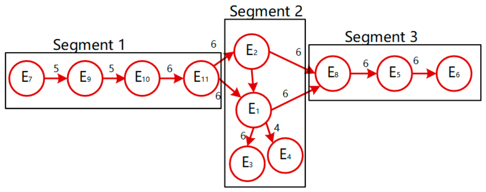
Step 2: Starting from the smallest distances, the primary chain is constructed. The sequence 9 to 10 to 11 to 2 to 1 to 8 to 5 to 6 is formed through coexistence relationships (0.3). Element 7 is appended to the head via the 7 to 9 sequence relationship (0.5), yielding the primary chain: 7 to 9 to 10 to 11 to 2 to 1 to 8 to 5 to 6.
Step 3: Elements 3 and 4 remain outside the primary chain. Element 3 only has a non-independent relationship with Element 1 (inclusion, 0.8) and independent relationships with all other primary chain elements. Element 4 only has a non-independent relationship with Element 1 (semi-confliction, 0.7) and independent relationships with all other primary chain elements. Both are recognized as branches attached to Element 1.
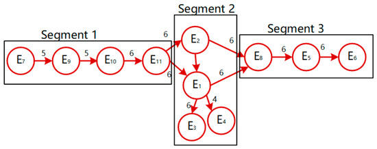
Step 4: Verification confirms all adjacent pairs in the primary chain have non-independent relationships. The resulting structure is illustrated in Figure 4, and the simplified design objectives are illustrated in Table 5.
Figure 4.
Reconstruction result.
Table 5.
Simplified design objectives.
5.4. Design Results
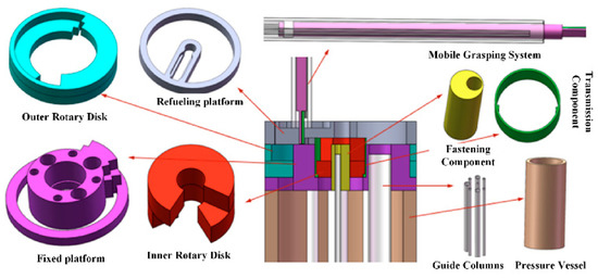
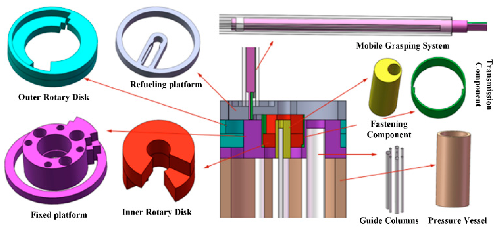
Based on the relevant design objectives and corresponding requirements, developed through iterative human–computer collaborative refinement, the final conceptual design of the product is illustrated in Figure 5.
Figure 5.
Schematic of the refueling device.
In fuel-handling operations, the mobile grasping system is installed vertically on the refueling platform, which can rotate. This design permits the two devices to access all positions in the pressure vessel and perform fuel extraction or placement operations. A fixed platform provides stability and ensures the support and positioning of internal guide columns. Transmission components drive the inner and outer rotary disks. After the mobile grasping system and refueling platform determine the placement position, the two-layer disks rotate to open the channel, ensuring the sealing and operational reliability of the entire system.
5.5. Discussion
The case study demonstrates both the feasibility and the limitations of the proposed simplification method. Several aspects warrant further discussion.
- (1)
- Complexity Reduction: The original element network contained 29 non-independent relationship pairs among 11 elements. After skeleton extraction, the simplified structure comprises eight edges in the primary chain and two branch attachments, totaling 10 expressed relationships, which represents a 65% reduction in relational complexity. The average relational degree per element decreased from 5.1 to 1.6. This quantitative evidence supports the claim that the method effectively decouples design objectives.
- (2)
- Correspondence Between Simplified Structure and Final Design: The simplified element structure directly guided the conceptual design of the refueling device. Segment 1, comprising Element 7 (penetration component), Element 9 (installed inside vessel), Element 10 (no complex electronics), and Element 11 (positioning structure), corresponds to the upper fixed platform and positioning mechanism in the final design. Segment 2, comprising Element 2 (extract solids) and Element 1 (move solids), forms the core functional pair, directly corresponding to the mobile grasping system. Branch Element 3 (extraction size) constrains the gripper geometry, and Branch Element 4 (avoid guide columns) determines the motion trajectory planning, both realized through the rotary arm and gripper design. Segment 3, comprising Element 8 (high reliability), Element 5 (prevent radiation leakage), and Element 6 (radiation-resistant materials), corresponds to the sealing system and shielding structure.
- (3)
- Method Limitations: The case reveals that when a single element serves as a hub connecting to multiple branches, the linear chain structure may not fully capture the design intent. The current method addresses this through branch recognition, but future work should explore hierarchical skeleton structures that better accommodate hub-centered relationships. Additionally, the subjective nature of distance assignment means that different designers may produce different simplified structures from the same requirements, which is both a limitation and a feature.
- (4)
- Response to Reviewer Concerns: Regarding the gap between algorithmic manipulation and practical implementation, the case demonstrates that the simplified structure directly translates into functional modules in the final design. Regarding the single-case limitation, while this case validates feasibility in nuclear reactor fuel-handling, the method’s generalizability to other complex product domains requires further validation. Regarding the absence of quantitative metrics, the 65 percent reduction in relational edge count and the correspondence mapping between simplified elements and final design components provide quantitative and qualitative evidence of effectiveness.
6. Conclusions
This paper presents an element-based iterative intent understanding method for complex product conceptual design. The main findings are summarized as follows:
- (1)
- An ontological element relationship model is established that defines seven intrinsic relationship types among function–performance–structure elements, providing a structured representation of design intent and enabling the transformation from user requirements to design objectives.
- (2)
- A skeleton-based simplification and reconstruction process is proposed, which extracts a primary element chain and identifies branch elements through distance assignment and systematic relational analysis, effectively reducing relational complexity while preserving essential design intent.
- (3)
- The feasibility of the proposed computational methodology is demonstrated through a refueling device case study, where the simplified element structure successfully guided the generation of conceptual design solutions that satisfy all user requirements.
The main contributions of this paper are as follows:
- (1)
- An ontology-based element relationship model that defines seven intrinsic relationship types among function–performance–structure elements, providing a structured representation of design intent. This model extends existing design ontologies by incorporating relationship semantics that capture interdependencies among design elements at multiple levels of abstraction.
- (2)
- A hierarchical function–performance–structure element decomposition framework that operationalizes the relationship model for complex product conceptual design. The framework provides a systematic methodology for decomposing user requirements into elemental components and establishing relationship networks that reflect design intent.
- (3)
- A computational methodology for intent understanding that is explicitly positioned as a foundational layer for future human–computer collaborative design systems. Rather than presenting a fully implemented interactive design-support system, this work establishes the formal basis—through element ontologies, relationship matrices, and algorithmic reconstruction—that can be integrated into future HCI frameworks. The case study in nuclear reactor fuel-handling system design demonstrates the feasibility and practical applicability of this computational approach in a real-world complex product design scenario.
Author Contributions
Conceptualization, Z.Y. and H.W.; methodology, Z.Y. and Y.L. (Yuhan Liu); design validation, H.W., G.F. and B.Y.; resources, Y.L. (Ying Luo); data curation, Y.L. (Yuhan Liu); writing—original draft preparation, Z.Y.; writing—review and editing, H.W. and G.F.; visualization, Z.Y.; funding acquisition, G.F. and Y.L. (Ying Luo); supervision, Y.L. (Ying Luo); project administration, B.Y. All authors have read and agreed to the published version of the manuscript.
Funding
This research was funded by the Fundamental Research Program of CNNC (CNNC-JCYJ-202410), the Sustained Support Project of CNNC (WDZC-2024-NKL004).
Data Availability Statement
The original contributions presented in this study are included in the article. Further inquiries can be directed to the corresponding author.
Conflicts of Interest
The authors declare no conflicts of interest. The funders had no role in the design of the study; in the collection, analyses, or interpretation of data; in the writing of the manuscript; or in the decision to publish the results.
References
- Mi, J.; Li, Y.F.; Peng, W.; Huang, H.Z. Reliability analysis of complex multi-state system with common cause failure based on evidential networks. Reliab. Eng. Syst. Safe 2018, 174, 71–81. [Google Scholar] [CrossRef] [Scilit]
- Li, Y.F.; Huang, H.Z.; Mi, J.; Peng, W.; Han, X. Reliability analysis of multi-state systems with common cause failures based on Bayesian network and fuzzy probability. Ann. Oper. Res. 2022, 311, 195–209. [Google Scholar]
- Guo, X.; Huang, Z.C.; Liu, Y.; Zhao, W.; Yu, Z.Y. Harnessing multi-domain knowledge for user-centric product conceptual design. J. Comput. Inf. Sci. Eng. 2023, 23, 060807. [Google Scholar] [CrossRef] [Scilit]
- Quan, W.; Rosen, D.W.; Song, B.Y. A review of generative artificial intelligence for additive manufacturing: Bridging design, process monitoring, and beyond. J. Manuf. Syst. 2026, 86, 393–416. [Google Scholar] [CrossRef] [Scilit]
- Zeng, Y.; Huang, T.; Zhang, T.; Huang, H.Z. System Level Performance Degradation Prediction for Power Converters Based on SSA Elman NN and Empirical Knowledge. IEEE T Ind. Inf. 2024, 20, 1240–1250. [Google Scholar] [CrossRef] [Scilit]
- Wiltschnig, S.; Christensen, B.T.; Ball, L.J. Collaborative problem-solution co-evolution in creative design. Des. Stud. 2013, 34, 515–542. [Google Scholar] [CrossRef] [Scilit]
- Bull, L.J.; Christensen, B.T. Advancing an understanding of design cognition and design metacognition: Progress and prospects. Des. Stud. 2019, 65, 35–59. [Google Scholar] [CrossRef] [Scilit]
- Huang, H.Z.; Li, H.; Shi, Y.; Huang, T.; Yang, Z.; He, L.; Liu, Y.; Jiang, C.; Li, Y.F.; Beer, M.; et al. Theory and application of possibility and evidence in reliability analysis and design optimization. JRSE 2025, 1, 15007. [Google Scholar] [CrossRef] [Scilit]
- Huang, T.; Xiahou, T.; Mi, J.; Chen, H.; Huang, H.Z.; Liu, Y. Merging multi-level evidential observations for dynamic reliability assessment of hierarchical multi-state systems: A dynamic Bayesian network approach. Reliab. Eng. Syst. Safe 2024, 249, 110225. [Google Scholar] [CrossRef] [Scilit]
- Huang, T.; Zhang, Q.; Beer, M.; Liu, Y.; Huang, H.Z. A dynamic reliability assessment method for multi-state manufacturing system by merging imprecise observational information. Reliab. Eng. Syst. Safe 2026, 266, 111722. [Google Scholar] [CrossRef] [Scilit]
- Stone, R.B.; Wood, K.L. Development of a functional basis for design. J. Mech. Des. 2000, 122, 359–370. [Google Scholar]
- Wang, T.C.; Li, H.; Wang, X.W. Extension design model of rapid configuration design for complex mechanical products scheme design. Appl. Sci. 2022, 12, 7921. [Google Scholar] [CrossRef] [Scilit]
- Chen, L.S.; Liu, C.H.; Hsu, C.C.; Lin, C.S. C-Kano model: A novel approach for discovering attractive quality elements. Total Qual. Manag. Bus. 2010, 21, 1189–1214. [Google Scholar] [CrossRef] [Scilit]
- Yang, Y.; Li, Q.; Li, C.; Qin, Q. User requirements analysis of new energy vehicles based on improved Kano model. Energy 2024, 309, 133134. [Google Scholar] [CrossRef] [Scilit]
- Xia, H.; Zhang, Y.; Li, X.; Liu, D.; Wang, W. Interface Design of VR Driverless Vehicle System on User-Prioritized Experience Requirements. Sensors 2025, 25, 5341. [Google Scholar] [CrossRef] [Scilit] [PubMed]
- Quan, H.; Li, S.; Wei, H.; Hu, J. Personalized Product Evaluation Based on GRA-TOPSIS and Kansei Engineering. Symmetry 2019, 11, 867. [Google Scholar] [CrossRef] [Scilit]
- Bringas, E.N.; Bowles, G.; Walker, G.H. Supporting complex decision making in learning space design: WDA-ANP, a novel sociotechnical systems approach. Facilities 2022, 40, 435–451. [Google Scholar] [CrossRef] [Scilit]
- Liu, H.; Li, Y.; Zhu, J.; Zhong, Y.; Chen, H. A Study on the Design of Living Spaces for Rural Tourism-Based Elderly Housing Driven by User Needs. Buildings 2025, 15, 2982. [Google Scholar] [CrossRef] [Scilit]
- Qian, S.J.; Mao, K.R.; Yi, X.Y. Embodied design strategies for autism-friendly museums: A Kano-QFD-PUGH-based user needs assessment. Front. Psychiatry 2025, 16, 1594445. [Google Scholar] [CrossRef] [Scilit] [PubMed]
- Feng, K.; Zhang, Z.L.; Ni, Q.; Yang, B.; Hu, Y.A.; Meng, L.H.; Lei, Y.G. Cognitive Digital Twin Enabled Aerospace Equipment: New Paradigm and Research Frontier. J. Mech. Eng. 2026, 62, 1–12. [Google Scholar] [CrossRef] [Scilit]
- Dou, R.L.; Li, W.; Nan, G.F. An integrated approach for dynamic customer requirement identification for product development. Enterp. Inf. Syst. 2019, 13, 448–466. [Google Scholar]
- Horan, L.F. The dynamic changes of customer requirements for sustainable design over time in quality function deployment. Prod. Manuf. Res. 2022, 10, 42–61. [Google Scholar] [CrossRef] [Scilit]
- He, L.; Ming, X.; Li, M.; Zheng, M.; Xu, Z. Understanding customer requirements through quantitative analysis of an improved fuzzy Kano’s model. Proc. Inst. Mech. Eng. B J. Eng. Manuf. 2017, 231, 699–712. [Google Scholar] [CrossRef] [Scilit]
- Wei, W.; Hao, C.L.; Wang, Z.X. User needs insights from UGC based on large language model. Adv. Eng. Inf. 2025, 65, 103268. [Google Scholar] [CrossRef] [Scilit]
- Liu, Y.; Zhang, D.; Wan, Q.; Lin, Z. Innovative Mining of User Requirements Through Combined Topic Modeling and Sentiment Analysis: An Automotive Case Study. Sensors 2025, 25, 1731. [Google Scholar] [CrossRef] [Scilit] [PubMed]
- Cui, H.; Zhang, X.; Liu, H.; Zhang, L.; Yan, Y. Tracing the evolution of user requirements: A sentiment analysis—Based method for smart PSS innovative design. J. Eng. Des. 2025, 37, 2277–2304. [Google Scholar] [CrossRef] [Scilit]
- Zhang, R.; Chen, Y.; Wang, K.; Shen, D.; Zhang, K.; Xia, W. Identification of User Requirements and their Influencing Factors Based on Online Reviews and Operational Data. J. Circuit Syst. Comp. 2024, 33, 2450288. [Google Scholar] [CrossRef] [Scilit]
- Zheng, L.; Song, T.; Ding, Y.; Wu, X.; Li, F.; Xie, D.; Li, J.; Teng, C.; Ji, D. Improving Emotion and Intent Understanding in Multimodal Conversations with Progressive Interaction. IEEE Trans. Affect. Comput. 2026, 17, 1030–1043. [Google Scholar] [CrossRef] [Scilit]
- Li, Z.; Tian, Z.G.; Wang, J.W.; Wang, W.M. Extraction of affective responses from customer reviews: An opinion mining and machine learning approach. Int. J. Comput. Integ M. 2020, 33, 670–685. [Google Scholar] [CrossRef] [Scilit]
- Lo, C.H.; Ko, Y.C.; Chiu, H.P. User Needs for a Robotic Hand Rehabilitation Device in Home-based Therapy Following a Stroke: A User-centered Approach. Sens. Mater. 2024, 36, 1731–1745. [Google Scholar] [CrossRef] [Scilit]
- Mao, L.X.; Lan, J.; Chen, A.Q.; Shi, H.; Liu, H.C. New approach for quality function deployment based on linguistic distribution assessments and CRITIC method. Mathematics 2025, 13, 240. [Google Scholar] [CrossRef] [Scilit]
- Zhang, K.; Zhao, W.; Wang, J.; Chen, L.; Wang, C.; Guo, X. Research on knowledge support technology for product innovation design based on quality function knowledge deployment. Adv. Mech. Eng. 2016, 8, 756493805. [Google Scholar] [CrossRef] [Scilit]
- Guo, X.; Wang, J.; Zhao, W.; Zhang, K.; Wang, C. Study of medical device innovation design strategy based on demand analysis and process case base. Multimed. Tools Appl. 2016, 75, 14351–14365. [Google Scholar] [CrossRef] [Scilit]
- Jiang, Y.; Guo, X.; Liu, Y.; Zhao, W. Knowledge-Based Design: A Function-Knowledge Reasoning Model for Product Conceptual Design. In Computational Design and Digital Manufacturing; Management and Industrial Engineering; Springer: Cham, Switzerland, 2023; pp. 119–139. [Google Scholar] [CrossRef] [Scilit]
- Kim, B.S.; Heo, I.S.; Karur, K.S.; Kim, S.H. Identifying communal user needs for quality of experience (QoE) evaluation and improvement focused on user-centered design. Acta Psychol. 2025, 260, 105622. [Google Scholar] [CrossRef] [Scilit] [PubMed]
- Arbelaez-Estrada, J.C.; Osorio-Gomez, G. Natural User Interface for color selection in conceptual design phase. Int. J. Interact. Des. M. 2017, 11, 45–53. [Google Scholar] [CrossRef] [Scilit]
- Jiang, Y.; Luo, Y.; Zhao, W.; Guo, X.; Liu, Y.; Zhang, K. An iterative process of product conceptual scheme based on performance constraints and rapid knowledge reuse. Comput. Ind. Eng. 2026, 211, 111639. [Google Scholar] [CrossRef] [Scilit]
- Afshari, H.; Peng, Q.J.; Gu, P.H. Design Optimization for Sustainable Products Under Users’ Preference Changes. J. Comput. Inf. Sci. Eng. 2016, 16, 41001. [Google Scholar] [CrossRef] [Scilit]
- Simpson, T.W.; Bobuk, A.; Slingerland, L.A.; Brennan, S.; Logan, D.; Reichard, K. From user requirements to commonality specifications: An integrated approach to product family design. Res. Eng. Des. 2012, 23, 141–153. [Google Scholar] [CrossRef] [Scilit]
- Liu, L.; Li, Y.; Xiong, Y.; Cavallucci, D. A new function-based patent knowledge retrieval tool for conceptual design of innovative products. Comput. Ind. 2020, 115, 103154. [Google Scholar] [CrossRef] [Scilit]
- Osman, M.A.; Noah, S.; Saad, S. Ontology-Based Knowledge Management Tools for Knowledge Sharing in Organization-A Review. IEEE Access 2022, 10, 43267–43283. [Google Scholar] [CrossRef] [Scilit]
- Deng, W.; Zhao, H.; Zou, L.; Li, G.; Yang, X.; Wu, D. A novel collaborative optimization algorithm in solving complex optimization problems. Soft Comput. 2017, 21, 4387–4398. [Google Scholar] [CrossRef] [Scilit]

Disclaimer/Publisher’s Note: The statements, opinions and data contained in all publications are solely those of the individual author(s) and contributor(s) and not of MDPI and/or the editor(s). MDPI and/or the editor(s) disclaim responsibility for any injury to people or property resulting from any ideas, methods, instructions or products referred to in the content. |
© 2026 by the authors. Published by MDPI on behalf of the International Institute of Knowledge Innovation and Invention. Licensee MDPI, Basel, Switzerland. This article is an open access article distributed under the terms and conditions of the Creative Commons Attribution (CC BY) license.