


Abstract
The effect of treatment time on arc-enhanced glow discharge plasma-assisted nitriding (AEGD-PAN) of AISI M2 high-speed steel was investigated for non-heat-treated and heat-treated substrates. Nitriding treatments were carried out at 350 °C for 1.5 and 3.5 h, producing diffusion layers with thicknesses ranging from approximately 38 to 75 µm without formation of a continuous brittle compound layer. X-ray diffraction combined with Rietveld refinement revealed the progressive formation of γ′-Fe4N and ε-Fe23N nitrides together with lattice expansion of the α-Fe matrix, indicating nitrogen supersaturation and precipitation strengthening within the diffusion zone. Heat-treated specimens exhibited higher surface hardness, reaching ~1350 HV0.1, while non-heat-treated substrates developed pronounced hardness gradients associated with diffusion-controlled layer growth. Scratch testing showed improved resistance to contact-induced damage with increasing nitriding time, particularly for the 3.5 h treatment, where lateral cracking was significantly reduced and load-bearing capacity increased. Multi-pass scratch wear tests revealed a reduction in the Archard wear coefficient by up to four orders of magnitude compared with untreated M2 steel. These results demonstrate that AEGD-PAN at moderate temperature enables efficient diffusion layer formation and significant improvement in the tribological performance of high-alloy tool steels.
1. Introduction
In the manufacturing sector, consumables for machinery, including cutting disks, dies, and drill bits, represent a significant production cost due to wear, corrosion, fracture, and a rapid performance degradation under continuous operation, as these components are subjected to severe mechanical and tribological loading. Their frequent replacement increases operational expenses and contributes to waste, as highlighted in the circular economy review by F. Acerbi & M. Taisch, which notes that such materials are rarely renewable [1]. Surface engineering offers an effective solution by enhancing surface properties of tool’s substrates [2], extending service life and reducing replacement frequency. This approach delivers clear technological, economic, and environmental benefits across industries, including metallurgical, automotive, biomedical, aeronautical, and food processing sectors [3,4,5].
Thermochemical surface engineering processes such as nitriding, carburizing, and nitrocarburizing are widely used in industry to enhance the performance of engineering materials, particularly steels [6,7]. These treatments improve key surface properties including hardness, wear resistance, friction behavior, corrosion resistance and thermal and electrical conductivity [8]. Thereby extending component service life under demanding operating conditions [9,10,11]. In addition to increasing surface hardness, they enhance fatigue resistance and overall tribological performance. Among these surface treatment methods, nitriding offers specific advantages over carburizing, as it does not involve phase transformation in the ferritic structures of steels, preserving core properties while strengthening the top surface [2,12,13]. Plasma-assisted nitriding (PAN) is typically carried out under low-pressure conditions (~100 Pa) at 400 and 450 °C using direct or pulsed current often with an applied bias to improve ion bombardment efficiency [14]. Compared to conventional gas nitriding, PAN operates at lower temperatures, minimizing distortions in the parts, maintaining bulk integrity, and reducing the need for post-treatment finishing due to its limited effect on surface roughness [15,16]. However, PAN also presents challenges. The formation of nitrogen networks (trapping effect) can promote defects such as cracking and spallation [2]. Additionally, decarburization in steels may occur, particularly during prolonged treatments. For instance, Sun and Bell [9] showed that increasing nitriding treatment time in En40B steel enhances decarburization but also promotes the formation of γ′-Fe4N, a phase associated with high mechanical strength. In contrast, excessive processing time, temperature, and high nitrogen content may lead to the formation of a white surface layer (white layer), which can degrade wear resistance and mechanical performance [17,18,19]. Despite these limitations nitride layers are highly valuable in duplex systems, where they act as a graded support to improve the adhesion and load-bearing capacity of hard coatings [3].
For industrial applications, short nitriding times are essential to ensure process efficiency and cost-effectiveness. Nevertheless, most PAN studies focus on prolonged treatments as reported for steels such as AISI 316L [20,21,22,23], AISI H13 [24,25] and AISI D2 [26,27,28]. In contrast, combining nitriding processes with prior heat treatments (e.g., quenching, tempering or cryogenic processing) has been proven effective in enhancing both physical and chemical properties. For AISI M2 steel, these approaches improve wear resistance, toughness and hardness by tailoring microstructure through controlled thermal cycles leading to increased durability [29,30].
AISI M2 steel is widely used in tooling, automotive, aerospace and metallurgical applications, particularly for cutting tools (e.g., disks, drills) and forming tools such as dies or molds [31]. Despite its relevance, limited research has addressed PAN of M2 in the annealed state, where the material retains high plasticity and machinability. Existing studies highlight potential drawbacks; for instance, Kwietniewski et al. [32] reported edge cracking due to deep and brittle diffusion zones, while Akbari et al. [33] showed that initial microstructures, modified by prior heat treatments, significantly affects the morphology and size of carbides, consequently modifying the diffusion kinetics of the nitriding process (PAN at 450 °C for 8 h). Moreover, such thermal treatments and PAN may induce decarburization and formation of brittle nitrides, underscoring the need for further investigation into phase stability, mechanical behavior, and wear performance of the nitride layer.
From the literature review it can be established that process modifications can further enhance nitriding efficiency. For instance, arc-enhanced glow discharge (AEGD) has been applied for surface cleaning processes and activation prior to nitriding or within duplex treatments, improving surface reactivity and increasing roughness compared to untreated material [34,35,36]. However, studies specifically addressing AEGD-assisted plasma nitriding (AEGD-PAN) remain limited.
In this study, the main objective is to contribute to the understanding of AEGD-assisted plasma nitriding (AEGD-PAN) in surface treatments, a relatively underexplored technique with significant potential for industrial applications. In particular, this approach aims to reduce processing times without compromising the improvement of material properties, considering that most conventional thermochemical treatments for steels typically require durations of 4 h or longer. In this context, the present work demonstrates that comparable or improved surface performance can be achieved using significantly shorter treatment times (1.5 h and 3.5 h).
Furthermore, the study evaluates the material response considering both untreated and heat-treated substrates, providing insight into the influence of the initial microstructural condition on the nitriding process. The combined effects of heat treatment and nitriding time on the mechanical strength and scratch resistance of AEGD-PAN layers on high-alloy M2 steel are systematically analyzed. The resulting surface properties are correlated with the nitride phase composition, surface morphology, roughness, hardness, and diffusion layer characteristics, allowing the establishment of comprehensive structure–property relationships
2. Materials and Methods
2.1. Heat Treatment of the M2 Steel
A set of the commercial AISI M2 (M2) steel samples (Ø 25.4 mm × 5 mm) was subjected to heat treatment in an AMP Hybri-Tec Quantum-G vacuum furnace (Warsaw, Poland) operating at a base pressure of 4 mPa. The samples were preheated at 870 °C for 60 min to reduce thermal gradients, distortion, and residual stress. Subsequently, austenitizing was then carried out at 1200 °C for 15 min with a heating rate of 3 °C/min. Quenching was performed using nitrogen gas at 800 kPa, rapidly cooling the samples to 50 °C. Immediately after this step, tempering was conducted at 580 °C for 120 min with a heating rate of 5 °C/min, followed by nitrogen cooling at 300 kPa. The chemical composition of the steel was determined by Glow Discharge Optical Emission Spectroscopy (GDOES) using a Horiba GD Profiler 2 spectrometer (Kyoto, Japan), as summarized in Table 1.
Table 1.
Chemical composition of commercial AISI M2 steel.
Before AEGD-PAN, the surfaces of the steel samples were treated with abrasive paper (180–1200), followed by a polishing step to a specular finish using diamond paste (3 µm), then ultrasonically cleaned in isopropyl alcohol, dried and fixed on the planetary sample holder to be placed in the reactor chamber. The AEGD-PAN treatment was performed on steel coupons in the annealed state and after heat treatment.
2.2. AEGD-PAN
The AEGD-PAN process was carried out in a Metaplas Domino Mini system from Oerlikon (Pfäffikon, Switzerland). The unit is equipped with an arc-enhanced cathodic arc discharge configuration using a shielded Ti cathode (diameter Φ = 5.08 cm, 99.5% purity) and a stainless steel anode to generate a high-density plasma [35]. Arc conditions were set using DC current of 80 A at the cathode and 85 A at the anode, combined with a pulsed bias of −250 V at 20 kHz and 80% duty cycle. Prior to nitriding, the samples were heated to 350 °C using a 9 kW radiant heater. Plasma cleaning for 15 min in an Ar (500 sccm and 1 Pa) under the same bias condition to remove contaminants and activate the surface. Subsequently, the samples were then plasma nitrided for 1.5 and 3.5 h. The corresponding processing parameters are summarized in Table 2.
Table 2.
AEGD-PAN parameters for AISI M2 tool steel samples.
2.3. Microstructural and Phase Analysis
The crystalline structure of the samples was analyzed by grazing-incidence X-ray diffraction (XRD) using a Rigaku SmartLab diffractometer (Tokyo, Japan) with a Cu-Kα radiation source (λ = 1.5406 Å). The analysis covered the 2θ range between 10 and 90°, a step of 0.01°/s and Ω = 1.5°. Phase quantification was performed by Rietveld refinement analysis, employing the fundamental parameters approach (FPA). Rigaku’s PDXL software (Version 2.3.1.0) was employed for the analysis, and correlation values were determined using the minimum method. The quality of the Rietveld refinement was assessed using the weighted profile R-factor (Rwp) and the goodness-of-fit parameter (S), with obtained values (Rwp < 3% and S < 1.09) indicating an excellent agreement between the experimental and calculated diffraction patterns.
The microstructure was further analyzed by high-resolution transmission electron microscopy (HRTEM) using a JEOL JEM-2200FS+Cs (Tokyo, Japan) equipped with a spherical aberration corrector in the condenser lens and operated at 200 kV. Selected area electron diffraction (SAED) was employed to support phase and crystallographic analysis. TEM lamellae were prepared by using a JEOL JEM-9320 (Tokyo, Japan) focused ion beam (FIB) system operated at 30 kV.
Additional microstructural characterization was performed by field emission scanning electron microscopy (FE-SEM) in a JEOL JSM-7200F (Tokyo, Japan). Nitrogen distribution across the cross-section was evaluated by EDS line scan strategy using an Ultim Max 100 from Oxford Instruments (Oxfordshire, UK). For this purpose, samples were sectioned with a diamond saw, mounted in Bakelite, polished to a mirror finish, and chemically etched with a 4 vol% Nital.
2.4. Mechanical Evaluation and Scratch Test
Vickers microhardness measurements were carried out on cross-sections by applying a 1 N load and 15 s dwell time with a pyramidal indenter in an Anton Paar Revetest equipment (Graz, Austria). Scratch resistance and failure modes were evaluated by dynamic and multi-pass static scratch tests (three repetitions per condition; see test conditions in Table 3) using a Rockwell C diamond stylus tip with a 200 µm radius. The failure loads, from the dynamic scratch tests, where obtained using a progressive load from 0.1 to 100 N over a 5 mm track. Critical failure loads were determined from friction coefficient curves and post-test examination of the wear tracks by FE-SEM. Multi-pass static scratch tests were conducted at a constant load of 50 N with 5 consecutive scratches along the same track. Wear tracks were further analyzed by confocal microscopy using an Olympus Digital DSX510 (Tokyo, Japan), and wear coefficients were calculated according to the Archard model [37].
Table 3.
Scratch test parameters of plasma-nitrided M2 steel surfaces.
3. Results
3.1. Substrate Microstructure
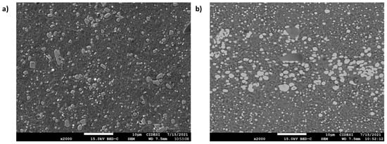
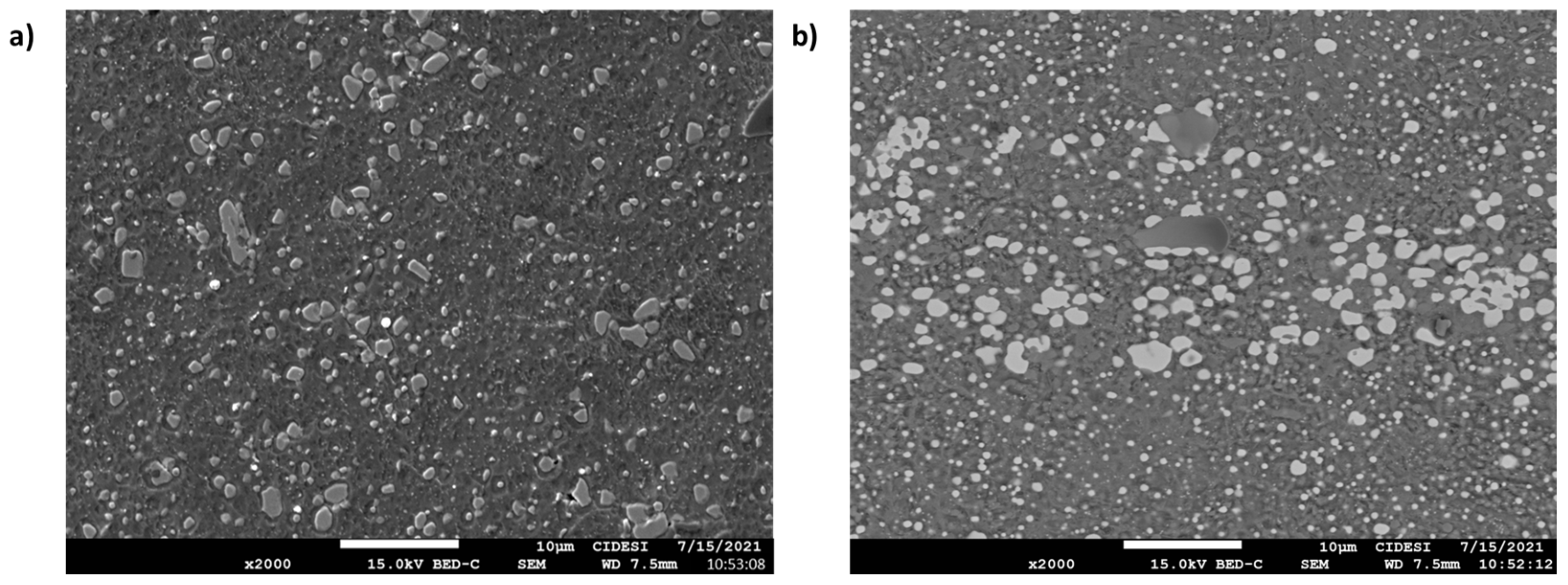
The initial microstructure of the M2 steel substrate was analyzed both in its as-received condition (without heat treatment) and after heat treatment (HT) using scanning electron microscopy (SEM) and energy-dispersive X-ray spectroscopy (EDS). For the untreated M2 steel shown in Figure 1a, the microstructure exhibits a metallic matrix with a dispersion of carbide particles of irregular morphology and heterogeneous size distribution. These carbides are relatively coarse and non-uniformly distributed, suggesting a microstructure dominated by primary carbides formed during solidification.
Figure 1.
SEM micrographs of M2 steel substrate in (a) as-received condition and (b) heat-treated condition.
EDS analysis performed on representative regions (Figure 1a) reveals that the matrix is predominantly composed of Fe (~81 wt.%), with the presence of alloying elements such as Cr (~4 wt.%), Mo, W, V, and Co in lower concentrations. The detection of strong carbide-forming elements (Cr, Mo, W, and V) supports the presence of different types of primary carbides. In particular, chromium-rich regions are indicative of M23C6 or M7C3-type carbides, while the presence of Mo and W suggests M6C carbides, and V is associated with MC-type carbides. The relatively low carbon signal detected by EDS is consistent with the known limitations of this technique for light elements, but still supports the presence of carbide phases.
In contrast, the substrate after heat treatment (Figure 1b) shows a more homogeneous microstructure, characterized by a refined dispersion of carbide particles embedded in the matrix. Elemental mapping by EDS reveals that these particles are enriched in strong carbide-forming elements, such as V, Mo, and W. Regions showing enrichment in vanadium are associated with MC-type carbides, while areas enriched in Mo and W correspond to M6C carbides, typical of high-speed steels after heat treatment. The matrix is consistent with a quenched martensitic structure. Compared to the as-received condition, the HT microstructure shows a more uniform distribution and refinement of carbides, indicating the transformation, partial dissolution, and redistribution of primary carbides during the heat treatment process. These microstructural differences are expected to significantly influence nitrogen diffusion and phase evolution during the AEGD-PAN treatment, as carbide size, distribution, and composition play a key role in nitrogen trapping and the formation of secondary phases.
3.2. Crystalline Structure and Phase Stability
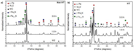
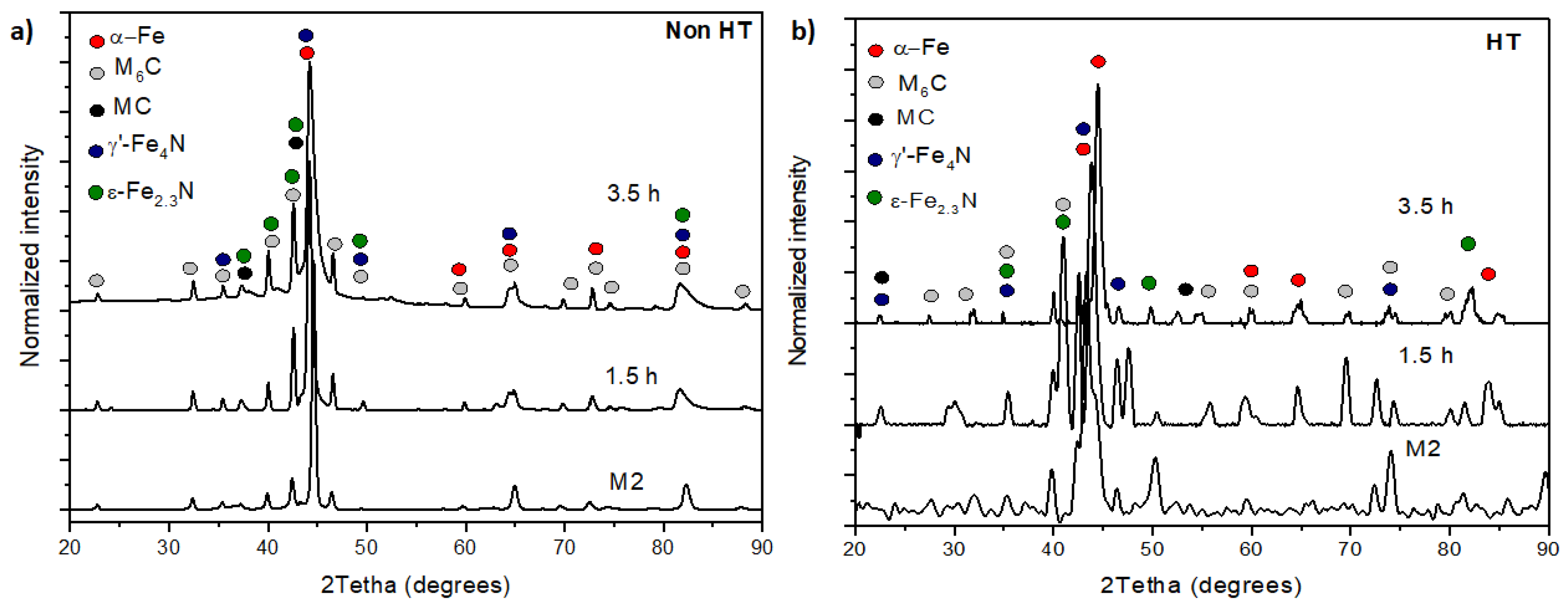
Figure 2a,b show the evolution and changes in the crystalline structure of M2 steel without heat treatment (non-HT) and with heat treatment (HT), before and after the AEGD-PAN process. The untreated M2 steel consists of a α-Fe crystalline matrix microstructure with dispersed M6C and MC carbides as widely reported in the literature by Akbari et al. [33], Rocha et al. [38], Pessin et al. [39], and Gill et al. [40]. The formation of carbides in M2 steel is strongly influenced by the electronic configuration of alloying elements; as noted by V. Lazić et al. [41], transition metals with partially filled d-orbitals (e.g., Cr, Mo, and W) promote carbide formation and stability (see Table 1). XRD patterns confirm the presence of M6C and MC carbides in all conditions. For the non-HT M2 steel, their diffraction intensities decrease with increasing nitriding time, while peaks corresponding to ε-Fe2,3N and γ′-Fe4N became more evident in the XRD patterns indicating the development of the nitride diffusion layer. The peak shift in the α-Fe matrix, together with the detection of carbide and nitride peaks, reveals the microstructural evolution of M2 steel induced by nitrogen incorporation in the AEGD-PAN process. In the HT samples a reduction in α-Fe phase is observed after quenching treatment, likely associated with the martensitic transformation, followed by a relative increase after nitriding, possibly attributed to the dissociation of carbides and ferrite stabilization at the process temperature.
Figure 2.
X-ray diffraction patters for the (a) as cast (non-HT) and (b) thermal-treated M2 steel before and after plasma nitriding at different times.
Rietveld refinement and transmission electron microscopy (TEM) support these observations, as discussed in Section 3.3. A detailed analysis of the peak in the 2θ = 43–46° region reveals a shift in such diffraction peak toward lower angles, indicating lattice expansion of α-Fe, while peak broadening suggests residual stresses and partial overlap with γ′-Fe4N phases (i.e., matrix expansion and nitride precipitation). The lattice parameter of the α-Fe phase increase from 2.870 Å to 2.901 Å after 3.5 h of the AEGD-PAN process, reflecting nitrogen diffusion into interstitial sites of the crystalline cells of the α-Fe matrix. The resulting nitrogen concentration gradients generate strain fields and thermal expansion mismatch between the nitrided layer and the bulk of the M2 leading to surface and subsurface stresses, consistent with previous reports from Akbari et al. [33] and Rousseau et al. [42].
Expanded austenite phase (S-phase), widely described in stainless steels [43] is associated with supersaturated solid solutions containing interstitial nitrogen (N) and/or carbon (C) atoms in the γ-Fe lattice, producing significant lattice expansion, which notably enhances hardness and impacts on other surface properties such as fatigue and wear resistance. Therefore, the primary objective of the quenching process in M2 steel is to obtain a predominantly martensitic microstructure [44]. XRD patterns after heat treatment confirm a microstructure consisting of martensite, retained austenite, and M6C/MC carbides [45]. In the present study, heat treatment induces an increase of approximately 2% in the lattice parameters, which correlates with enhanced in surface hardness and improved abrasion resistance of the steel.
Analysis of the XRD patterns of the base M2 steel, with (HT) and without heat treatment (non-HT), prior to nitriding reveals characteristic ferritic α-Fe peaks at 2θ = 44.6°, 65.0°, and 82.3° corresponding to the (110), (200), and (211) crystallographic planes, respectively. These reflections confirm the presence of a predominantly ferritic matrix in the non-treated steel. After heat treatment, the intensity of the aforementioned α-Fe peaks decreases, consistent with partial dissolution of ferrite and the formation of martensite and retained austenite during quenching and tempering. Additionally, peaks associated with M6C- and MC carbides appear in the 2θ ranges 37–46° and 60–75°, suggesting precipitation and growth of secondary carbides.
3.3. Rietveld Analysis and Phase Quantification
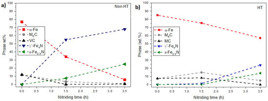
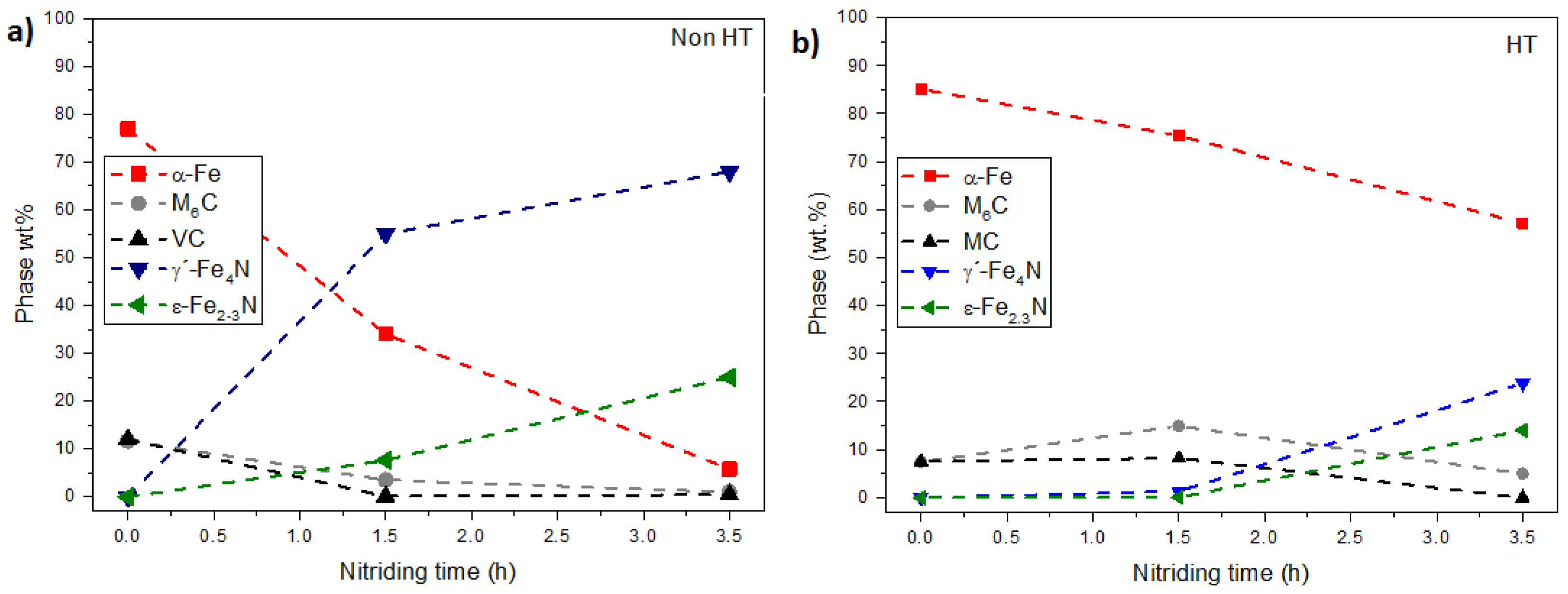
Figure 3 presents the phase fractions of the α-Fe matrix phases, carbides, and nitrides obtained by Rietveld refining as a function of nitriding time. For non-HT samples (Figure 3a), the α-Fe phase decreases nearly linearly with increasing nitriding time, reaching ~30% after 3.5 h. Compared to the HT samples (Figure 3b), the α-Fe decrease is evident and exhibit smaller variations with nitriding time, while the γ phase becomes evident. In non-HT steel, the M6C carbides fraction decreases from its initial value to 4.8 wt.% after 1.5 h of nitriding and further to 3.5 wt.% after 3.5 h. In contrast, HT steel samples subjected to nitriding exhibit overall lower carbide fractions after 3.5 h of treatment. The formation of γ′-Fe4N and ε-Fe2,3N nitrides confirms the effectiveness of the plasma nitriding. For non-HT steels, ε-Fe2,3N reaches ~30 wt.% after 3.5 h, while the γ′-Fe4N phase reached peak concentration of ~55 wt.% after 1.5 h and increased to approximately 68 wt.% after 3.5 h of nitriding, at the expense of the iron content.
Figure 3.
Identification of Rietveld Phases from the XRD patterns for the as cast (a) and thermal-treated M2 steel (b) as a function of nitriding time.
In HT-nitrided steel, the ε-Fe2,3N phase increases by 4–15 wt.%, whereas the γ′-Fe4N phase rises from 10 to 25 wt.% as nitriding time extends from 1.5 to 3.5 h. The reduction in α-Fe content and lattice expansion observed in the diffusion layer (DL) result from progressive nitrogen incorporation, leading to local equilibrium and subsequent transformations of the matrix and carbides into γ′-Fe4N and ε-Fe2,3N. These phase evolutions and microstructures are consistent with the diffusion zone transformations reported in previous studies [33,46].
Although Rietveld’s refinement did not explicitly reveal carbonitride formation during nitriding, it cannot be completely excluded. After 3.5 h of AEGD-PAN, only minor fractions of carbides were detected. MC was nearly absent, while M6C was present in limited amounts, particularly in the HT condition (~5 wt.%). This behavior suggests partial destabilization of pre-existing carbides under high nitrogen activity, along with possible carbon redistribution during the treatment. In high-alloy ferritic steels, this behavior has been linked to carbon diffusion toward the surface under high nitrogen activity. Nayebpashaee et al. [10] and Steiner & Mittemeijer [12] reported that nitrogen atoms can partially replace carbon atoms in carbide interstitial sites, promoting the formation of nitrides and carbonitrides. Similarly, Sun & Bell [9] associated the reduction M6C content with early-stage decarburization as nitride phases stabilize. These observations indicate that near-equilibrium conditions between the matrix, carbides and nitrides, are approached within the composite layer.
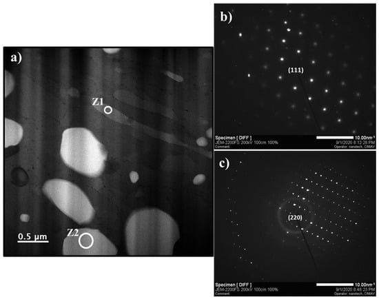
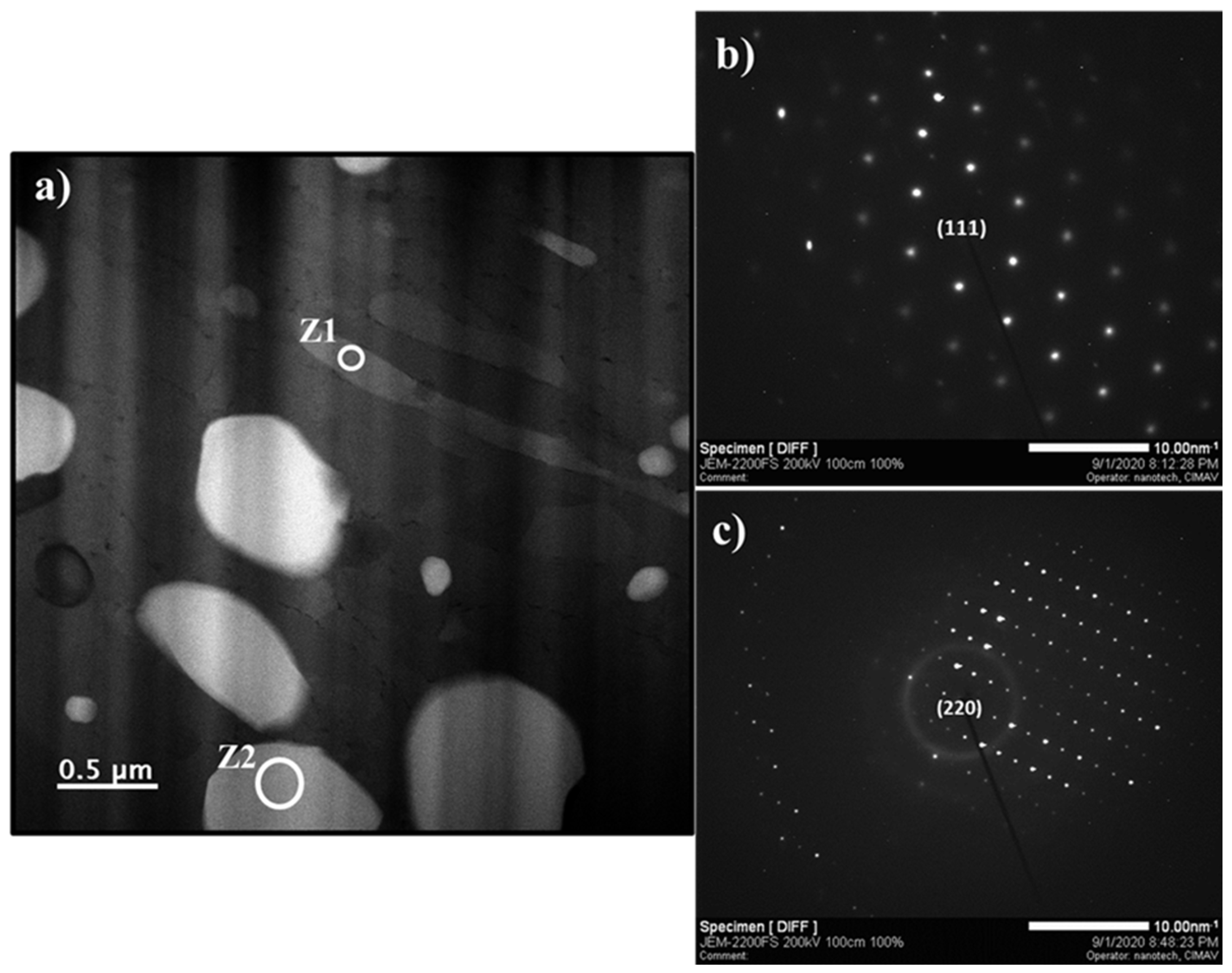
To further elucidate phase formation of nitrides and carbides, HRTEM/SAED analyses were performed on representative AISI M2 HT tool steel samples nitrided for 3.5 h. The low-magnification HAADF (High-angle annular dark field)-STEM cross-section (Figure 4a) reveals the α-Fe matrix and the dispersed precipitates; the brightest rounded precipitates correspond to Co3W3C phase (M6C-type), consistent with Z-contrast imaging due to the high atomic number of W. SAED patterns acquired from regions Z1 and Z2 (Figure 4b,c) confirm phase identity.
Figure 4.
TEM image of the plasma-nitrided zone from the HT M2 steel. (a) Low-magnification cross-section HAADF-STEM, (b) SAED from zone 1 (Z1) and (c) SAED from zone 2 (Z2).
In Z1 an interplanar spacing of 2.074 Å corresponding to the (111) plane matches Fe3N phase (space group P6322) consistent with the Powder Diffraction File (PDF) 79982 and in agreement with the high nitride fraction determined in the Rietveld analysis. In Z2, an interplanar spacing 2.074 Å indexed to the (220) plane correspond to Co3W3C (space group Fd-3m), in agreement with the PDF 01-078-3750. As shown in Figure 4a, these precipitates exhibit lamellar morphology within the columnar sublayer, where large ε columns formed during nitriding are partially segmented by formation of γ-Fe4N plates upon cooling, a microstructural feature also reported by Liu et al. [47,48].
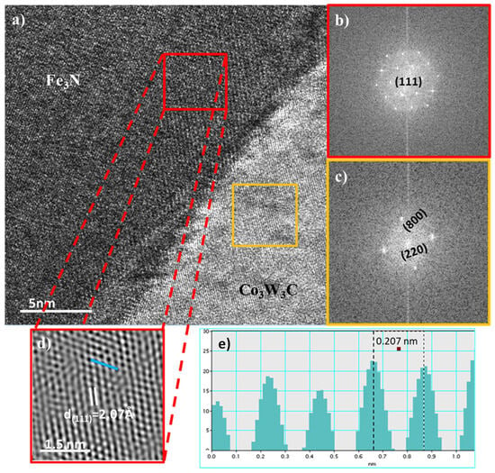
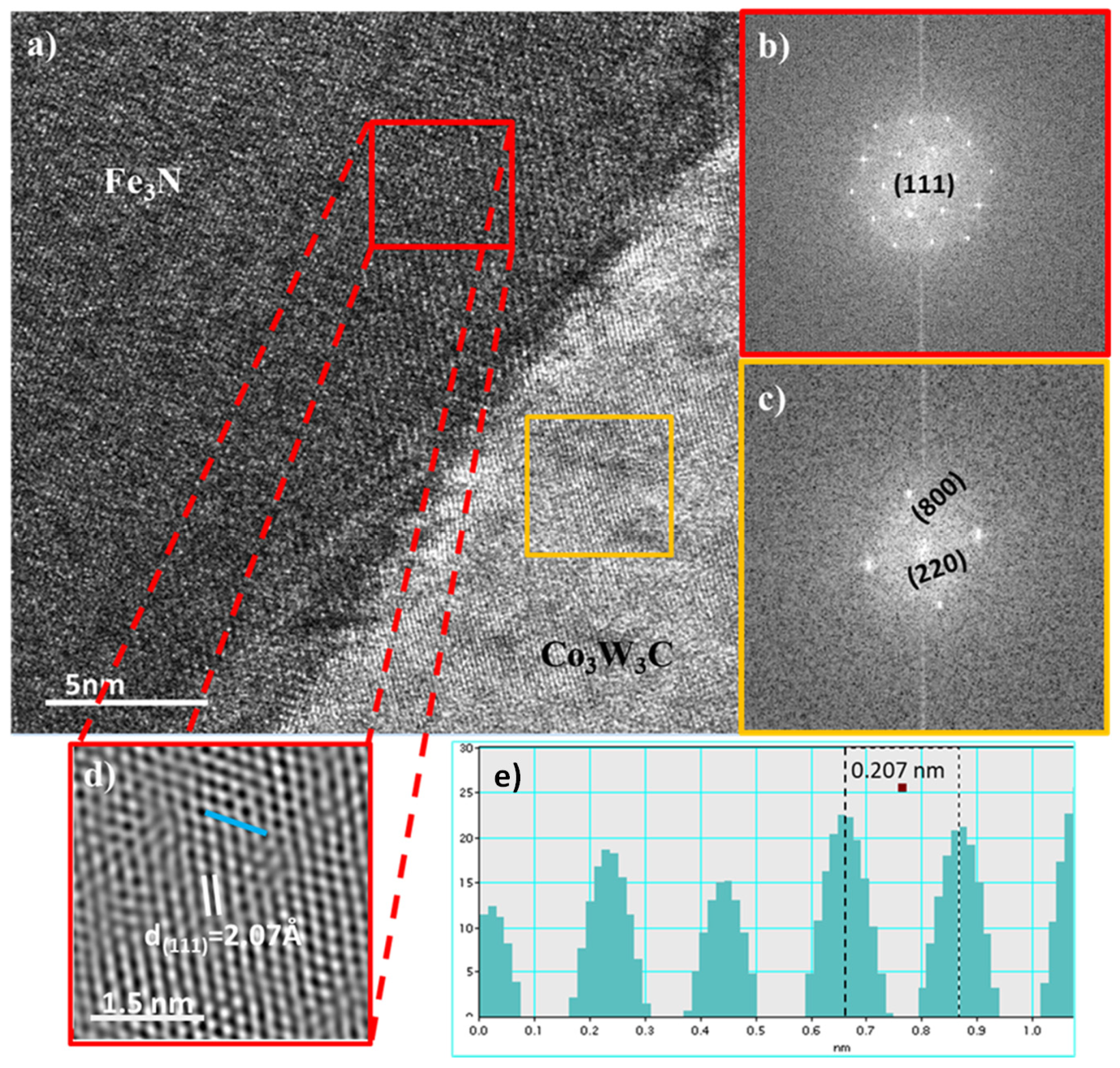
Figure 5a presents a high-resolution image of the interface between the nitrided matrix and a precipitate, revealing a well-defined phase boundary. The identification of Fe3N and Co3W3C confirms the coexistence of nitride and carbide phases at the nanoscale. Fast Fourier Transform (FFT) analysis of the selected regions (Figure 5b,c) allow the determination of the corresponding crystallographic planes. The Fe3N phase is indexed along the (111) plane with an interatomic distance of d = 2.074 Å (space group P6322) consistent with PDF 79982. In contrast, the cubic Co3W3C phase is oriented along the (800) and (220) planes, with interplanar spacing distances of 1.378 Å and 3.897 Å, respectively, matching PDF 00-031-1403.
Figure 5.
(a) High-resolution image of the transition between the nitrided matrix and a precipitate, (b,c) Fast Fourier Transform (FFT) analysis of a region marked with a square, (d) close-up of the red frame and (e) the cross-section of the atomic planes along the marked blue line.
The magnified view of the interface shown in Figure 5a, and the intensity profile (Figure 5e) along the marked blue line (Figure 5d) confirm the d(111) = 2.074 Å spacing of the Fe3N phase. These results allow us to clarify the formation of iron nitrides and their interaction with pre-existing carbides in the matrix, supporting the phase evolution identified by XRD and Rietveld analysis.
3.4. Diffusion Layers
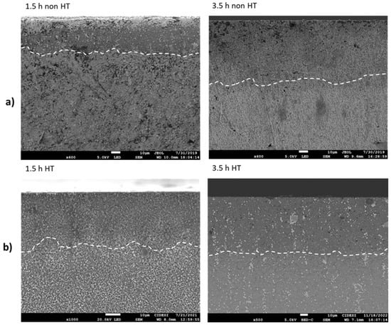
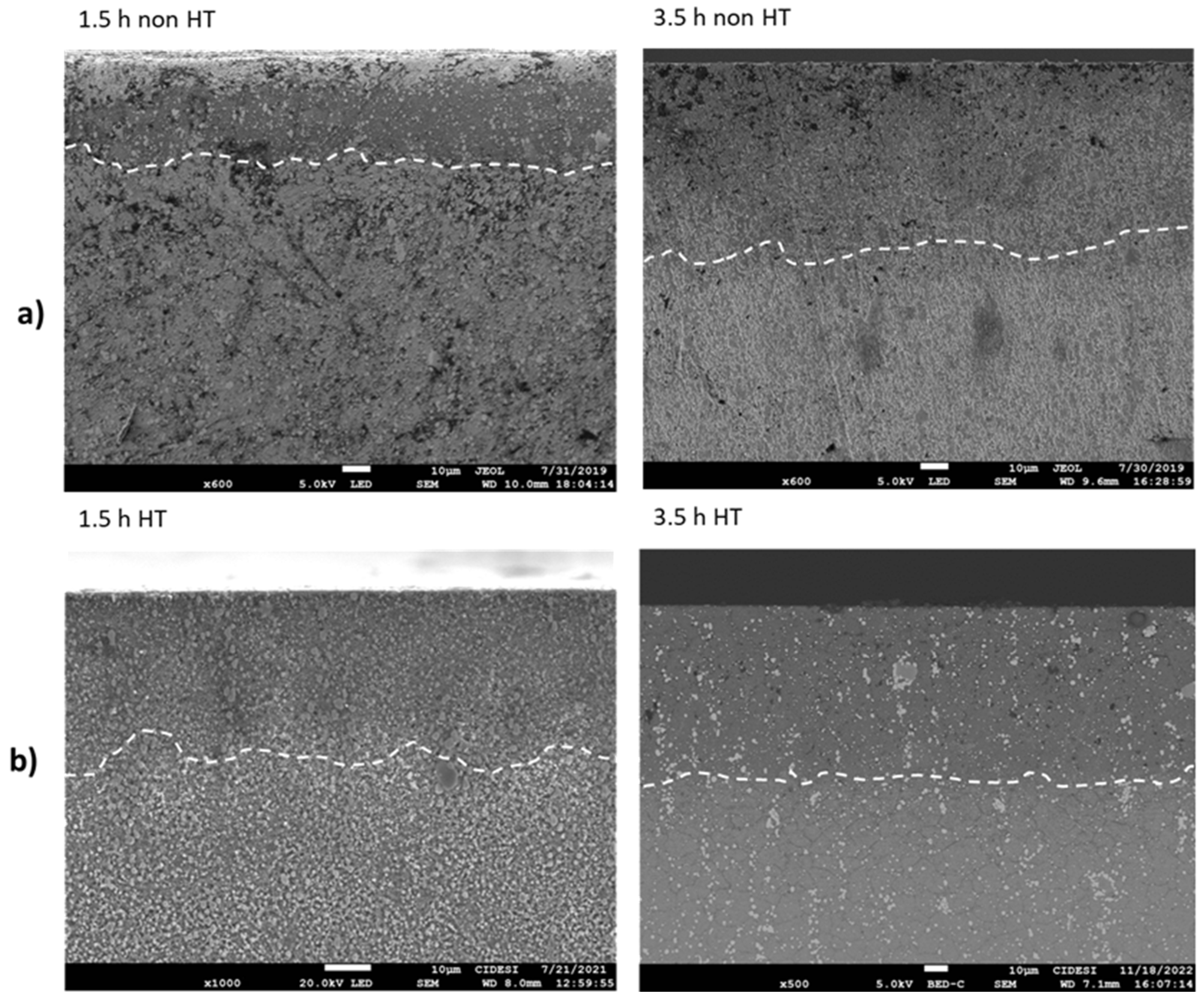
Figure 6a,b illustrate the effect of AEGD-PAN processing time on the diffusion layer (DL) thickness in M2 steel substrates without (non-HT) and with prior heat treatment (HT), respectively. For both nitriding times (1.5 and 3.5 h), two distinct regions developed, characterized by nitrogen concentration gradients extending from the surface toward the core of the alloy. The outermost region consists of a compound layer of γ′-Fe4N and ε-Fe2,3N phases. Beneath this, the region defining the DL consists mainly of the γ’-Fe4N phase and M6C carbide precipitates (M = W, Mo, Co) located at the grain boundaries of the α-Fe matrix, followed by a zone containing alloy precipitates with a gradual reduction in the γ′-Fe4N phase fraction. Previous studies by Akbari et al. [33] and Hudis [46] reported that ion nitriding produces nitride-rich zones near the surface, while the DL is distinguished by a progressive decrease in the ε phase content. The innermost nitrided region corresponds to the transition zone between the nitride layer and the M2 steel core.
Figure 6.
N diffusion layer for different times and experimental conditions (a) without HT and (b) with HT. The dotted lines indicate the boundary between the diffusion layer and the core of the material.
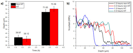
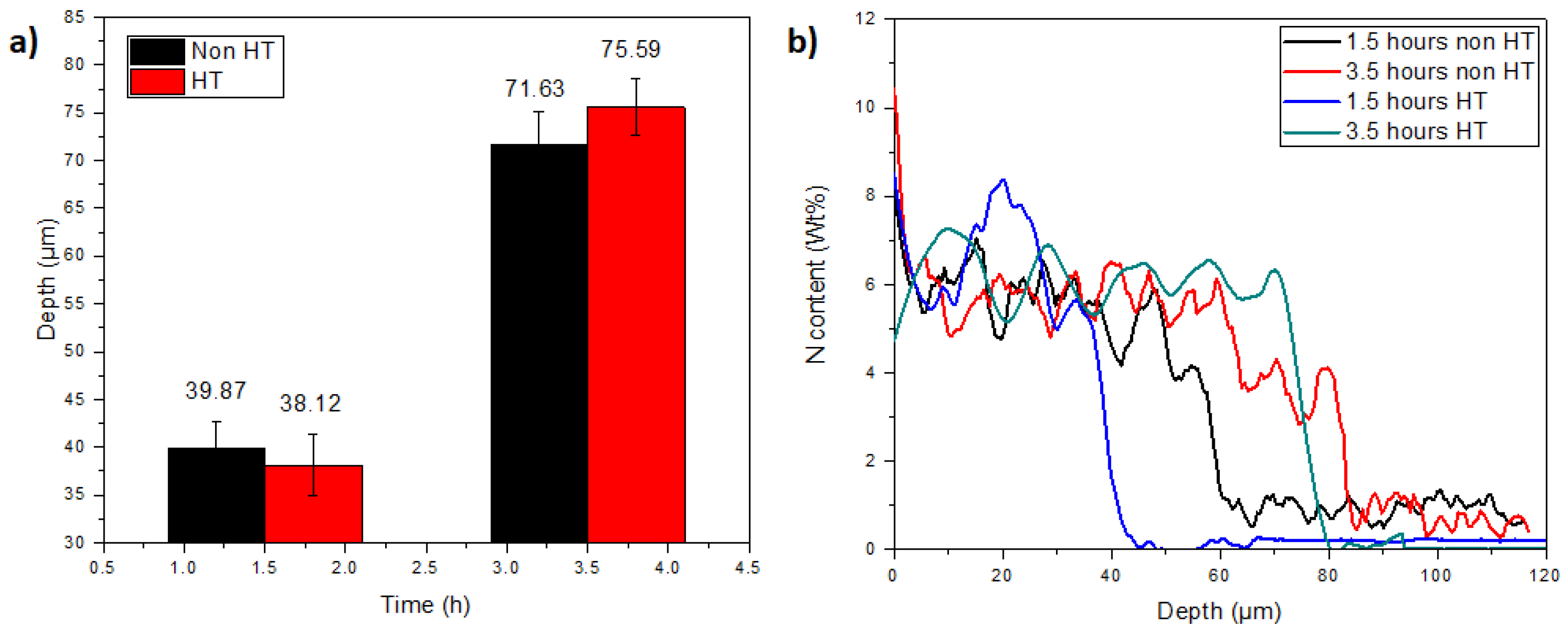
SEM analysis confirm the formation of well-defined diffusion zones in all samples. For substrates without a nitriding treatment, average DL thicknesses of 39.87 µm and 71.63 µm were obtained after 1.5 and 3.5 h nitriding, respectively. Similarly, HT steel substrates exhibited DL thicknesses of 38.12 µm and 75.59 µm for the same nitriding times (Figure 7a). These results demonstrate that nitriding time has a direct and significant influence on the DL thickness, with a pronounced increase between 1.5 and 3.5 h, regardless of prior heat treatment.
Figure 7.
(a) Nitrogen diffusion depth over time and (b) EDS nitrogen from the cross-section profiles of the M2 steel after plasma nitriding.
Although the DL in the HT substrates was slightly thinner at 1.5 h, a greater depth was achieved at 3.5 h (75.59 µm) compared to the non-HT condition (71.63 µm). This behavior suggests that, over extended periods, the heat-treated microstructure may facilitate improved nitrogen incorporation. Such an effect may be associated with progressive dissolution of carbides and the activation of additional diffusion pathways.
In M2 steel, the presence of carbides introduces competition between carbonitrides formation and nitrogen diffusion. In non-HT specimens, the higher fraction of primary, less dissolved carbides may initially restrict nitrogen mobility, limiting short-term diffusion. Over longer treatment times, partial carbide dissolution can release alloying elements that react with nitrogen, contributing to the increased DL thickness observed at 3.5 h. In contrast, carbide refining during HT samples may promote rapid nitride formation; however, this could also lead to early nitrogen saturation, potentially limiting initial diffusion depth. The formation of a compound layer (CL) on high-alloy steels depends on the balance among the nitrogen dissociation rate, the partial pressure, and ion bombardment energy. As reported by Sun and Bell [9] and Avelar-Batista et al. [11], CL growth during plasma nitriding is strongly affected by ion bombardment, which increases proportionally with argon partial pressure. Under the thermochemical treatment conditions employed in this study, no continuous compound layer was detected on the steel surface in any of the ground conditions examined (Figure 6).
The DL obtained indicate that the nitrogen chemical potential exceeded the threshold required to achieve a high nitrogen ionization rate and sufficient ion bombardment energy in both specimens, resulting in well-defined diffusion zones. Figure 7b presents the nitrogen concentration profiles obtained by EDS as a function of depth for M2 steel samples with (HT) and without prior heat treatment (non-HT). At the surface, non-HT samples exhibit nitrogen contents between 7 and 11 wt.%, consistent with the compound layer identified by FE-SEM. Within the internal diffusion zone, the nitrogen concentration decreased to values between 4 and 6.5 wt.%.
The observed fluctuations in nitrogen content are attributed to local microstructural heterogeneities. Similar depth profiles have been reported by Kwietniewski et al. [32] and Nayal et al. [49] for M2 steel subjected to different ion nitriding processes (cold wall and pulsed plasma), respectively. For HT-treated samples, nitrogen contents of approximately 6 to 10 wt.% were measured near the surface, while values in the diffusion zone fluctuates between 5 and 7 wt.% at depths of 40–80 μm. In relation to nitrogen diffusion, a slightly lower nitrogen penetration was observed in the HT condition, which can be associated with the precipitation of nitride phases after tempering. These phases modify nitrogen transport and correlate with the higher surface hardness measured in HT samples compared to the non-HT condition.
The relationship between the nitride layer thickness, determined from FE-SEM micrographs, and treatment time describes the growth kinetics of the diffusion layer (Figure 7a). Deviations from an ideal parabolic growth law were observed. Such deviations are commonly associated with concurrent surface sputtering effects and complex diffusion phenomena in high-alloy steels, including nitrogen saturation, bulk decarburization, and inhomogeneous nitride precipitation within the diffusion layer. D’Haen et al. [50] and Albarran et al. [51] demonstrated that inhomogeneous nitride precipitation is promoted by high concentrations of alloying elements such as Cr, V, Mo, and W, which reduce diffusion uniformity. Given the alloy composition of M2 steel (see Table S1), these effects are expected to contribute to non-parabolic DL growth, and to the non-uniform boundary observed between the nitrided zone and the steel core (dotted line in Figure 6). Strictly parabolic kinetics have been mainly reported for gas nitriding processes, as shown theoretically and experimentally by D’Haen et al. [50], Dimitrov et al. [52] and Figueroa et al. [53].
Table 4 compares the DL thicknesses obtained in this study with those reported for plasma nitriding of M2 steel. Diffusion layer thickness is strongly influenced by processing parameters such as operating mode, gas composition, polarization voltage, temperature, and treatment time. For example, Avelar-Batista et al. [11] reported DL thicknesses of 100–150 μm after 4 h of DC triode nitriding at 480 and 500 °C without hydrogen; increasing the N2 fraction by 10% reduced the DL thickness by approximately 50 μm. At shorter nitriding times (30–60 min), Dimitrov et al. [52] and Figueroa et al. [53] observed DL thicknesses below 60 μm when applying a DC potential and using hydrogen instead of argon. These values are comparable to those obtained in the present study. R. Mohammadzadeh et al. [18], using an RF system in floating potential mode and 8 h of nitriding in N2 + H2 mixtures, reported diffusion zones up to 100 μm thick. In the present work, the combination of prior HT, N2/Ar/H2 gas mixtures and the plasma-assisted AEGD process enhanced surface activation and ion density within the chamber, thereby promoting effective nitriding of high-alloy M2 steel.
Table 4.
Process parameters of plasma nitriding of AISI M2 steel and CL/DL characteristics.
3.5. Mechanical Properties
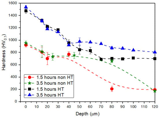
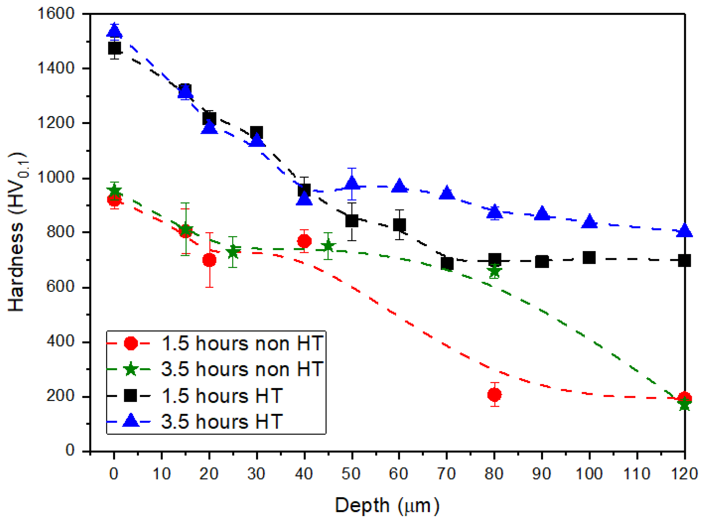
Vickers hardness (HV) is a reliable criterion for determining the thickness of DL and identifying the boundary with the M2 steel core. Cross-sectional microhardness profiles of the nitrided samples are shown in Figure 8. For nitrided samples without prior heat treatment (non-HT), surface hardness values between 700 and 900 HV0.1 were measured up to depths of ~40 μm, independent of the nitriding time. This represents an increase of ~460% relative to the untreated steel. After 3.5 h of nitriding, elevated hardness values extended to depths of ~80 μm, consistent with the DL thicknesses determined by FE-SEM/EDS (Figure 6 and Figure 7). At depths greater than 120 μm, hardness values approach those of the bare M2 steel, 192.3 ± 5 HV0.1. The hardness increase is attributed to the formation of stable nitride phases ε-Fe2,3N and γ′-Fe4N, as confirmed by XRD and TEM (Figure 4, Figure 5 and Figure 6), as well as to compressive residual stresses developed by nitrogen solid solution within the α-Fe matrix. For M2 steel with prior HT followed by nitriding, surface hardness values between 1200 and 1350 HV0.1 were obtained for both processing times, corresponding to an increase of ~700% relative to the hardness of the base M2 steel. Moreover, sustained hardness values of ~700 HV0.1 were observed at depths around 120 μm, representing an increase of nearly 300% compared to the non-nitrided M2 steel. These results indicate that second phase precipitation is the dominant strengthening mechanism at all nitriding times, regardless of the DL thickness.
Figure 8.
Hardness trends as a function of the depth within the nitriding compound and diffusion layers of non-HT and HT M2 steel samples.
3.6. Scratch Resistance
Two scratch testing methodologies were employed to simulate wear induced by hard particle abrasion of the nitrided surfaces: (i) a dynamic scratch test with a single-step progressive load and (ii) a multi-pass static scratch test under constant load. Each result represents the average of three highly reproducible measurements. Figure 8 compares representative scratch tracks generated for base M2 steel (without HT and with HT) and nitrided conditions.
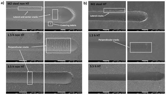
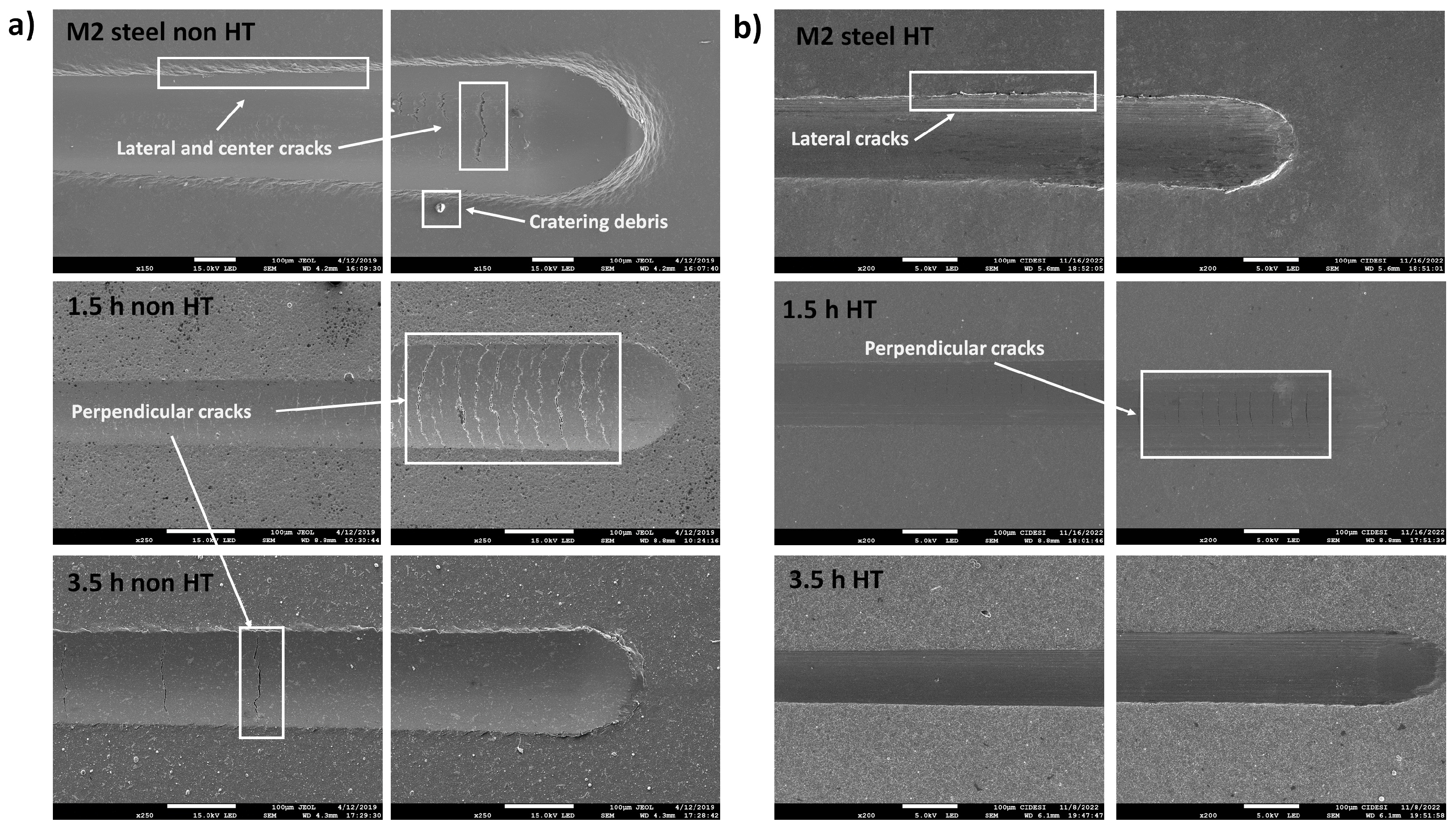
During dynamic scratching, untreated M2 steel (non-HT) exhibited primarily plastic deformation and groove formation, without significant debris accumulation or spallation up to a load of 40.7 N. At higher loads, lateral and transverse cracks developed at the groove edges and center, respectively, with crack size increasing as the load progressed. The lower plastic deformation resistance of the untreated M2 steel facilitates a ductile response, whereas nitrided samples show a transition toward a more brittle DL + M2 substrate system, as evidenced in single-pass scratch tests. For samples nitrided for 3.5 h, a combination of grooves, lateral cracks, and circumferential cracks were observed at greater scratching distances (Figure 9a).
Figure 9.
Evaluation of the dynamic scratch tracks on M2 steel for different nitriding conditions (a) non-HT and (b) with HT.
In M2 steel samples with prior HT, well-defined lateral cracks were largely absent along most of the groove, suggesting a plastic deformation response with significant material drag, indicative of higher deformation capacity prior to fracture. This behavior promotes stress accommodation and delays the nucleation of lateral cracks. In contrast, M2 HT steel samples nitrided for 1.5 h displayed regular lateral microcracks near the midpoint of the scratch track (≈2.5 mm, corresponding to ≈50 N). These cracks, oriented nearly perpendicular to the scratching direction, are associated with residual tensile stresses and tensile forces generated by the lateral groove expansion. This behavior reflects the high hardness of the nitrided layer combined with a moderate reduction in toughness, which can be attributed to the formation of brittle nitride phases, residual stress development, and microstructural modifications such as carbide destabilization. These factors promote controlled microfracture for stress relief without leading to catastrophic spalling. For HT samples nitrided for 3.5 h, SEM analysis revealed fewer but more pronounced lateral cracks, some exhibiting larger openings and localized propagation towards the surface, particularly near the end of the scratch path. This suggests that longer nitriding times produced a harder but also more brittle surface layer, capable of storing greater elastic energy prior to fracture and promoting abrupt crack nucleation rather than distributing micro-cracking. This behavior is consistent with increased nitride content (ε-Fe2,3N and γ′-Fe4N) and higher residual stresses within the composite layer. It should be noted that the absence of extensive lateral cracking may indicate improved toughness; however, excessive brittleness can aversively affect wear resistance under severe service conditions.
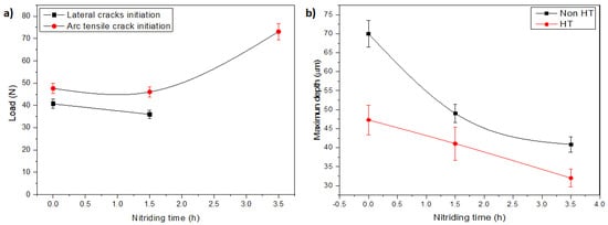
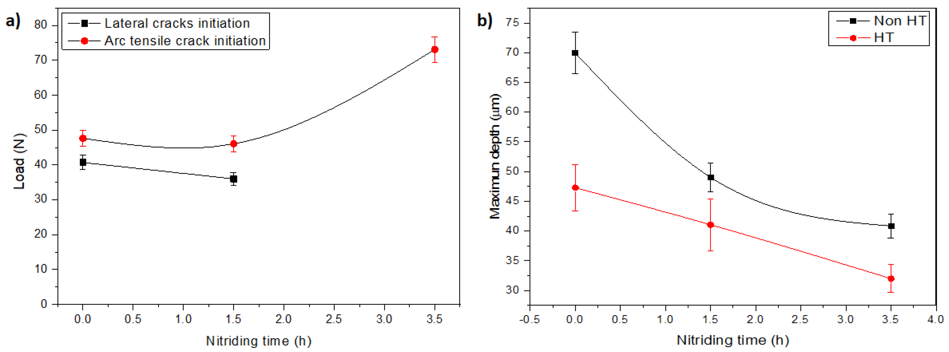
The presence of circumferential cracks indicates that the dominant failure mechanism is governed by tensile stresses generated behind the indenter during scratching. As reported in the studies of Steinmann et al. [58] and Bull [59], tensile arc cracks observed at shorter nitriding times are characteristic of brittle surfaces layers, particularly those containing iron nitrides. In contrast, the appearance of longitudinal cracks and the absence of tensile arc cracks after 3.5 h of nitriding (Figure 9) suggest an elastoplastic surface response, similar to that of untreated M2 steel but with significantly mechanical strength. As shown in Figure 10b, the maximum penetration depth of the scratch track does not exceed the thickness of the diffusion layer. For nitriding times shorter than 3.5 h, crack formation indicates that the DL is insufficient to fully accommodate and redistribute the applied load. Conversely, samples nitrided for 3.5 h exhibited no visible crack formation and showed the shallowest penetration depths (Figure 9a,b), indicating enhanced resistance to fracture. This improved performance is consistent with the more homogeneous microstructure observed within the nitriding zone under these nitriding conditions (Figure 6 and Figure 7).
Figure 10.
(a) Evaluation of cracks generation from the dynamic scratch tests and (b) wear depth from the static scratch tests a function of nitriding time.
It is noteworthy that nitriding treatments lead to an increase in microhardness and resistance to plastic deformation compared to the untreated condition. Although the surface hardness values for the 1.5 h and 3.5 h treatments are comparable, the 3.5 h condition exhibits a more gradual hardness decrease with depth, indicating the formation of a thicker diffusion layer. This results in improved load-bearing capacity and enhanced resistance to plastic deformation under applied load. In contrast, shorter nitriding times produce a steeper hardness gradient, which may limit the mechanical support of the surface layer. Although prolonged nitriding can promote the formation of continuous ε-Fe2,3N networks associated with increased brittleness, this condition was not reached with the 3.5 h of nitriding treatment, as confirmed by the absence of a continuous white layer.
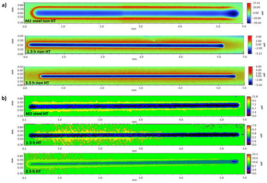
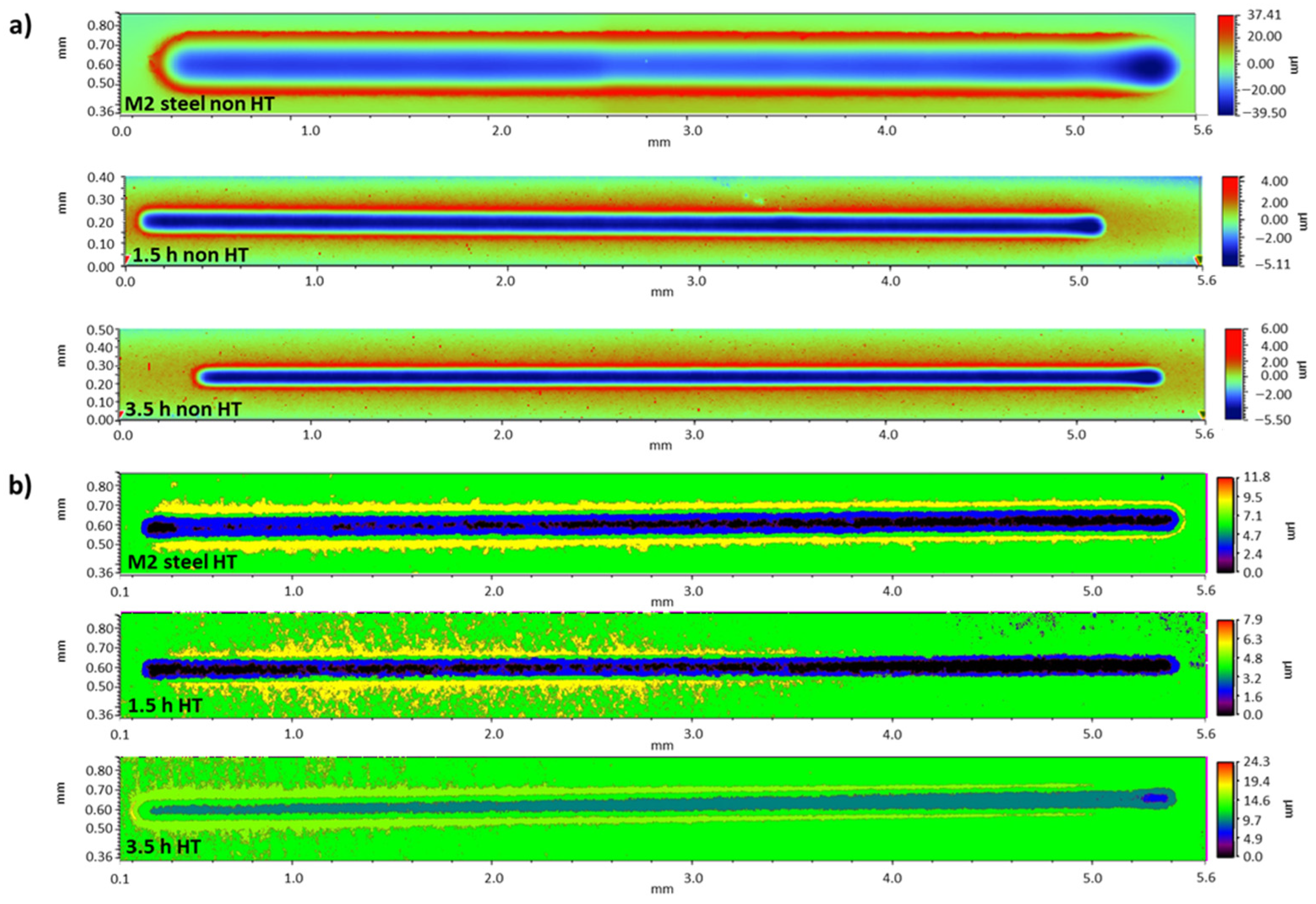
Regarding multi-pass static scratching, five successive wear tracks were produced on each nitrided surface to determine the wear coefficient (test conditions in Table 3). Figure 11 shows the 3D surface profiles of the resulting scratch tracks of the non-HT and HT after different nitriding conditions. As expected, non-treated M2 steel exhibited the widest track and the greatest maximum depth (~20 µm). For M2 steel with prior HT, the maximum depth was reduced to ~10 µm, although significant pile-up was still observed at the track edges of the M2 steel non-HT.
Figure 11.
Multi-pass static scratch test wear tracks from (a) non-heat-treated M2 steel and (b) heat-treated M2 steel for different nitriding times.
Nitrided samples under both conditions showed a clear improvement in scratch resistance. Increasing nitriding time led to a reduction in both the track width and depth, with maximum depths approaching ~5 µm for HT specimens. Additionally, material accumulation at the track edges decreased significantly. The reduced penetration is attributed to enhanced resistance to strain hardening during successive scratching passes, which becomes more pronounced with longer nitriding times due to the formation of hard nitride and carbide phases. Xu et al. [60] demonstrated the influence of strain hardening on scratch resistance in low-alloy steels, concluding that multi-step scratch testing provides detailed insight into wear mechanisms. In the present study, the absence of debris or chips at the end of the tests, combined with the presence of displaced material along the track edges, indicates that wear occurs predominantly by a plowing mechanism. According to Kayaba et al. [61], chipping and cutting modes are characterized by the chip formation ahead of the indenter and minimal material accumulation at the groove edges, features that were not observed here.
The wear coefficient k in [mm3/Nm] was obtained using the Archard model (Equation (1)) [37],
k = (V)(HV)/Ld
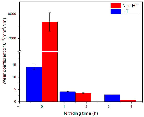
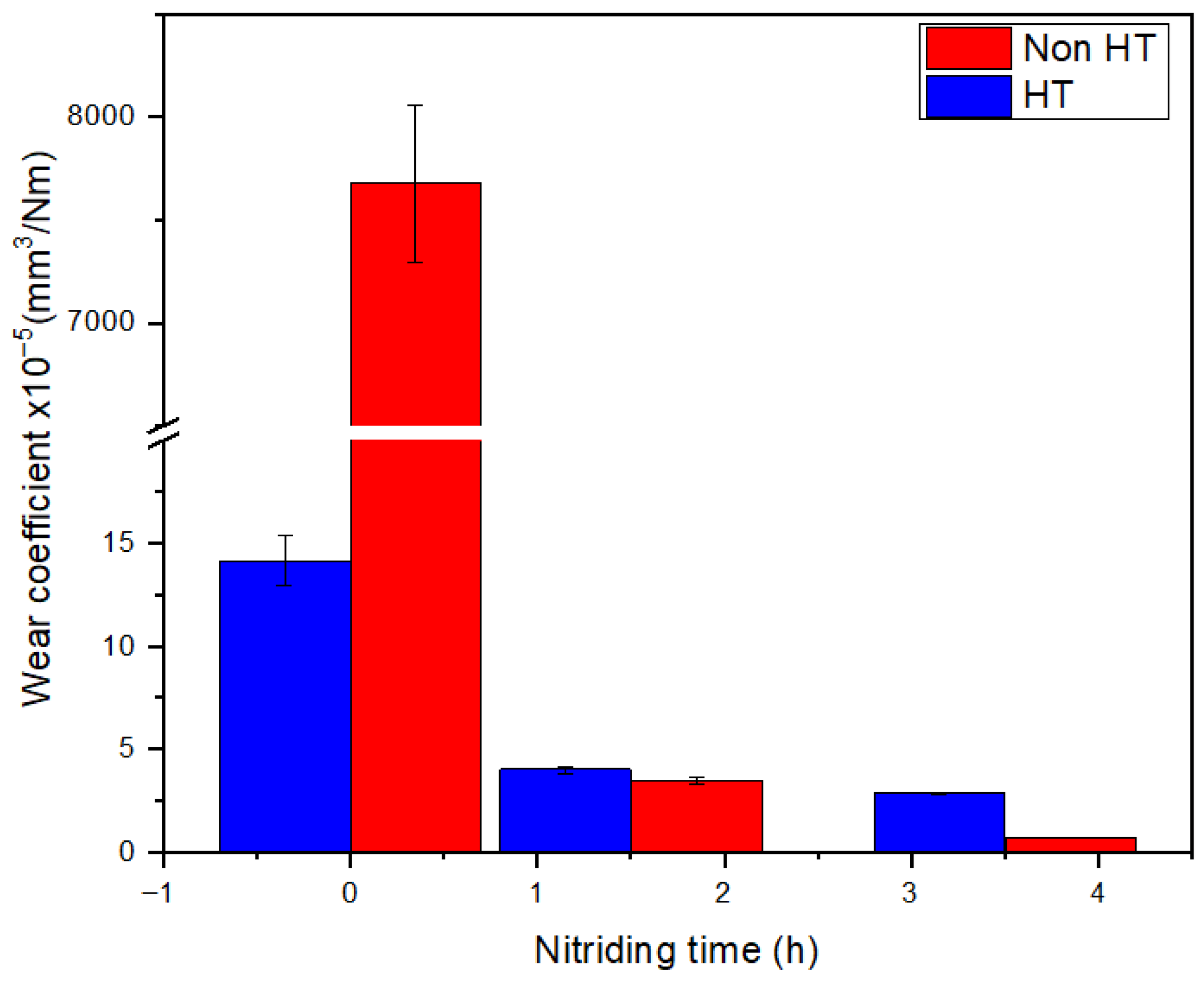
In this model V represents the wear volume determined by profilometry, HV is the Vickers hardness obtained by microindentation, L is the applied load, and d is the sliding distance obtained from the static scratch test. Figure 12 presents the calculated wear coefficients. For non-heat-treated (non-HT) M2 steel, nitriding significantly reduced the wear coefficients. Decreases of approximately three and four orders of magnitude were observed after 1.5 h and 3.5 h of nitriding, respectively.
Figure 12.
Wear coefficients of M2 steel after different nitriding conditions, non-HT and HT specimens.
For heat-treated (HT) M2 steel, Figure 12 also shows the wear coefficients for both the bare steel and nitrided conditions. Unlike the non-HT steel, the HT substrate already exhibited a substantial improvement in tribological behavior prior to nitriding, with a reduction in two orders of magnitude in wear coefficient compared to untreated non-HT steel. After 1.5 h of nitriding, the wear coefficient decreased by additional ~ 0.5 orders of magnitude relative to the base material, while after 3.5 h, the reduction reached ~ 0.7 orders of magnitude. This improvement is attributed to the homogeneous martensitic structure produced by heat treatment, which enhances base hardness and promotes a more uniform nitrogen distribution during nitriding. Consequently, a denser and more mechanically stable composite layer is formed, leading to better wear resistance. The differences in wear coefficients between the HT steel compared to the non-HT steel system are therefore directly related to the distinct mechanical responses of the DL + M2 steel system identified in the previous microstructural and mechanical characterizations.
4. Conclusions
The effect of heat treatment and arc-enhanced glow discharge-assisted plasma nitriding (AEGD-PAN) time on the surface characteristics of M2 high-alloy steel was systematically investigated. The main findings are summarized as follows:
- The diffusion layer thickness increased with nitriding time, reaching up to ~75 μm after 3.5 h. Nitrogen saturation and heterogeneous nitride precipitation contributes to the formation of a non-continuous interface between the diffusion layer and the steel substrate.
- A slight carbon enrichment was detected in the DL region after 1.5 h of AEGD-PN for both non-HT and HT samples. However, XRD, Rietveld refinement, and HRTEM/SAED analyses showed no significant limitation to inward nitrogen diffusion. The predominant phases formed during the nitriding of M2 steel were γ′-Fe4N, ε-Fe2,3N, M6C carbides and MC carbides.
- Precipitation strengthening associated with nitride formation, combined with residual stresses arising from lattice mismatch, produced surface hardness increases exceeding 400% in non-HT samples. In HT specimens, heat treatment alone produced an increase of ~400%, and subsequent nitriding resulted in hardness values exceeding 750% of the untreated M2 steel.
- Non-HT-nitrided samples exhibited reduced lateral cracking and a predominance of plastic deformation with increasing nitriding time during dynamic scratching, and surface grooves after 3.5 h of nitriding, surface failure occurred at higher loads than in the untreated steel, indicating improved resistance to contact-induced damage. The HT samples showed no catastrophic failures during dynamic scratching testing under any condition, demonstrating improved load-bearing capacity of the material.
- Strain hardening was observed in the non-HT samples after 1.5 h of nitriding. After 3.5 h of nitriding the wear coefficient decreased by approximately four orders of magnitude relative to untreated M2 steel. For the HT samples, wear resistance improved by 2.7 orders of magnitude compared to the original material. Additional improvements of 3.2 and 3.7 orders of magnitude were achieved for 1.5 h and 3.5 h of nitriding, respectively.
- Overall, the combination of heat treatment and AEGD-PAN process significantly improved the mechanical and tribological performance in M2 high-alloy steel. A nitriding time of 3.5 h provided the most favorable balance between hardness and toughness.
Supplementary Materials
The following supporting information can be downloaded at: https://www.mdpi.com/article/10.3390/jmmp10050150/s1, Table S1: Crystallographic information of the different phases obtained from the Rietveld analysis.
Author Contributions
S.M.G.: Investigation, Writing—Original Draft Preparation; L.B.S.: Investigation, Writing—Original Draft Preparation; A.R.: Conceptualization, Writing—Review and Editing, Supervision; J.F.V.C.: Data Curation, Writing—Review and Editing; A.H.-M.: Data Curation, Writing—Review and Editing, Conceptualization; G.C.M.-R.: Conceptualization, Writing—Review and Editing, Supervision; J.A.V.-V.: Data Curation, Writing—Review and Editing, Conceptualization; J.M.G.-C.: Conceptualization, Writing—Review and Editing, Project Administration, Funding Acquisition. All authors have read and agreed to the published version of the manuscript.
Funding
This research was funded by SECIHTI through the programs: Frontiers of Science (project 1077-02-2015), FORDECYT (projects 297265 and 296384) and Researchers for Mexico program. CIDESI internal projects QD057 and QV0072. Universidad Tecnológica de Pereira through the project “Influencia de los parámetros del plasma en las propiedades mecánicas y tribológicas del acero AISI M2 funcionalizado por nitruración asistida por plasma por el método AEGD” with code 3-25-8.
Data Availability Statement
The data supporting the results presented in this paper will be available upon reasonable request to the corresponding author. This restriction is due to the fact that the information is part of an ongoing research project, the results of which are still being analyzed and developed within a larger project. However, to ensure scientific transparency and the reproducibility of the results, the authors agree to provide the relevant datasets to interested researchers, provided the request is justified and does not interfere with the progress or confidentiality commitments associated with the ongoing project.
Acknowledgments
The authors gratefully acknowledge the financial support provided by SECIHTI through the programs: Frontiers of Science (project 1077-02-2015) and FORDECYT (projects 297265 and 296384) and CIDESI internal projects QD057 and QV0072. The authors also thank V.M. Hurtado Pájaro for his contribution and assistance with sample preparation and his support during nitriding. J.M. González-Carmona, G.C. Mondragón-Rodriguez, and J.A. Villada-Villalobos acknowledge the SECIHTI-funded Researchers for Mexico program. Likewise, we thank Universidad Tecnológica de Pereira for the support for the development of the project “Influencia de los parámetros del plasma en las propiedades mecánicas y tribológicas del acero AISI M2 funcionalizado por nitruración asistida por plasma por el método AEGD” with code 3-25-8.
Conflicts of Interest
The authors declare no conflict of interest.
References
- Acerbi, F.; Taisch, M. A literature review on circular economy adoption in the manufacturing sector. J. Clean. Prod. 2020, 273, 123086. [Google Scholar] [CrossRef] [Scilit]
- Pye, D. Practical Nitriding and Ferritic Nitrocarburizing; ASM International: Novelty, OH, USA, 2003. [Google Scholar]
- Navinsek, B.; Panjan, P.; Urankar, I.; Cvahte, P.; Gorenjak, F. Improvement of hot-working processes with PVD coatings and duplex treatment. Surf. Coat. Technol. 2001, 142–144, 1148–1154. [Google Scholar] [CrossRef] [Scilit]
- Vetter, J.; Barbezat, G.; Crummenauer, J.; Avissar, J. Surface treatment selections for automotive applications. Surf. Coat. Technol. 2005, 200, 1962–1968. [Google Scholar] [CrossRef] [Scilit]
- Liang, H.; Shi, B.; Fairchild, A.; Cale, T. Applications of plasma coatings in artificial joints: An overview. Vacuum 2004, 73, 317–326. [Google Scholar] [CrossRef] [Scilit]
- Strid, J.; Easterling, K. On the chemlstry and stability of complex carbides and nitrides in microalloyed steels. Acta Met. 1985, 33, 2057–2074. [Google Scholar] [CrossRef] [Scilit]
- Pang, W.K.; Low, I.M. Understanding and Improving the Thermal Stability of Layered Ternary Carbides and Nitrides. In Advances in Ceramic Matrix Composites, 2nd ed.; Elsevier Inc.: Amsterdam, The Netherlands, 2018; pp. 429–460. [Google Scholar] [CrossRef] [Scilit]
- Damon, J.; Schüßler, P.; Mühl, F.; Dietrich, S.; Schulze, V. Short-time induction heat treatment of high speed steel AISI M2: Laboratory proof of concept and application-related component tests. Mater. Des. 2023, 230, 111991. [Google Scholar] [CrossRef] [Scilit]
- Sun, Y.; Bell, T. Plasma surface engineering of low alloy steel. Mater. Sci. Eng. A Struct. Mater. 1991, 140, 419–434. [Google Scholar] [CrossRef] [Scilit]
- Nayebpashaee, N.; Soltanieh, M.; Kheirandish, S. A study on formation and growth mechanism of nitride layers during plasma nitriding process of plastic injection mold steel. Mater. Manuf. Process. 2016, 31, 1192–1200. [Google Scholar] [CrossRef] [Scilit]
- Avelar-Batista, J.C.; Spain, E.; Housden, J.; Matthews, A.; Fuentes, G.G. Plasma nitriding of Ti6Al4V alloy and AISI M2 steel substrates using D.C. glow discharges under a triode configuration. Surf. Coat. Technol. 2005, 200, 1954–1961. [Google Scholar] [CrossRef] [Scilit]
- Steiner, T.; Mittemeijer, E.J. Alloying element nitride development in ferritic Fe-based materials upon nitriding: A Review. J. Mater. Eng. Perform. 2016, 25, 2091–2102. [Google Scholar] [CrossRef] [Scilit]
- Mittemeijer, E.J. Fundamentals of Nitriding and Nitrocarburizing. In ASM Handbook, Volume 4A, Steel Heat Treating Fundamentals and Processes; ASM International: Novelty, OH, USA, 2013; pp. 619–646. [Google Scholar] [CrossRef] [Scilit]
- Czerwiec, T.; Renevier, N.; Michel, H. Low-temperature plasma-assisted nitriding. Surf. Coat. Technol. 2000, 131, 267–277. [Google Scholar] [CrossRef] [Scilit]
- Grill, A.; Itzhak, D. Nitriding of AISI M2 tool steel in an inductive R.F. plasma. Thin Solid Films 1983, 101, 219–222. [Google Scholar] [CrossRef] [Scilit]
- Drouet, M.; Le Bourhis, E. Low temperature nitriding of metal alloys for surface mechanical performance. Materials 2023, 16, 4704. [Google Scholar] [CrossRef] [Scilit] [PubMed]
- Karamış, M.B. Some effects of the plasma nitriding process on layer properties. Thin Solid Films 1992, 217, 38–47. [Google Scholar] [CrossRef] [Scilit]
- Mohammadzadeh, R.; Akbari, A.; Drouet, M. Microstructure and wear properties of AISI M2 tool steel on RF plasma nitriding at different N2-H2 gas compositions. Surf. Coat. Technol. 2014, 258, 566–573. [Google Scholar] [CrossRef] [Scilit]
- Ram Mohan Rao, K.; Nouveau, C.; Trinadh, K. Low temperature plasma nitriding of low alloy steel for the enhancement of hardness. Mater. Today Proc. 2019, 17, 26–33. [Google Scholar] [CrossRef] [Scilit]
- Sun, Y.; Bell, T. Sliding wear characteristics of low temperature plasma nitrided 316 austenitic stainless steel. Wear 1998, 218, 34–42. [Google Scholar] [CrossRef] [Scilit]
- Duarte, M.C.S.; Godoy, C.; Avelar-Batista Wilson, J.C. Analysis of sliding wear tests of plasma processed AISI 316L steel. Surf. Coat. Technol. 2014, 260, 316–325. [Google Scholar] [CrossRef] [Scilit]
- Samanta, A.; Chakraborty, H.; Bhattacharya, M.; Ghosh, J.; Sreemany, M.; Bysakh, S.; Rane, R.; Joseph, A.; Jhala, G.; Mukherjee, S.; et al. Nanotribological response of a plasma nitrided bio-steel. J. Mech. Behav. Biomed. Mater. 2017, 69, 584–599. [Google Scholar] [CrossRef] [Scilit] [PubMed]
- Tromas, C.; Stinville, J.C.; Templier, C.; Villechaise, P. Hardness and elastic modulus gradients in plasma-nitrided 316L polycrystalline stainless steel investigated by nanoindentation tomography. Acta Mater. 2012, 60, 1965–1973. [Google Scholar] [CrossRef] [Scilit]
- Karamiş, M.; Gerçekcioǧlu, E. Wear behaviour of plasma nitrided steels at ambient and elevated temperatures. Wear 2000, 243, 76–84. [Google Scholar] [CrossRef] [Scilit]
- Leite, M.V.; Figueroa, C.A.; Corujeira Gallo, S.; Rovani, A.C.; Basso, R.L.O.; Mei, P.R.; Baumvol, I.J.R.; Sinatora, A. Wear mechanisms and microstructure of pulsed plasma nitrided AISI H13 tool steel. Wear 2010, 269, 466–472. [Google Scholar] [CrossRef] [Scilit]
- Uma Devi, M.; Chakraborty, T.K.; Mohanty, O.N. Wear behaviour of plasma nitrided tool steels. Surf. Coat. Technol. 1999, 116–119, 212–221. [Google Scholar] [CrossRef] [Scilit]
- Conci, M.D.; Bozzi, A.Ô.C.; Franco, A.R. Effect of plasma nitriding potential on tribological behaviour of AISI D2 cold-worked tool steel. Wear 2014, 317, 188–193. [Google Scholar] [CrossRef] [Scilit]
- She, D.; Yue, W.; Fu, Z.; Gu, Y.; Wang, C.; Liu, J. The effect of nitriding temperature on hardness and microstructure of die steel pre-treated by ultrasonic cold forging technology. Mater. Des. 2013, 49, 392–399. [Google Scholar] [CrossRef] [Scilit]
- Parcianello, C.T.; Fantineli, D.G.; Rosendo, T.S.; Reguly, A.; Tier, M.A.D. Influence of the heat treatment on the mechanical and tribological properties of cryogenically treated AISI M2 steel. J. Mater. Res. Technol. 2023, 26, 6462–6475. [Google Scholar] [CrossRef] [Scilit]
- Asif, M.; Ahad, M.A.; Iqbal, M.F.H.; Reyaz, S. Experimental investigation of thermal properties of tool steel and mild steel with heat treatment. Mater. Today Proc. 2021, 45, 5511–5517. [Google Scholar] [CrossRef] [Scilit]
- Araújo, A.G.F.; Naeem, M.; Araújo, L.N.M.; Costa, T.H.C.; Khan, K.H.; Díaz-Guillén, J.C.; Iqbal, J.; Liborio, M.S.; Sousa, R.R.M. Design, manufacturing and plasma nitriding of AISI-M2 steel forming tool and its performance analysis. J. Mater. Res. Technol. 2020, 9, 14517–14527. [Google Scholar] [CrossRef] [Scilit]
- Kwietniewski, C.; Fontana, W.; Moraes, C.; da Rocha, A.S.; Hirsch, T.; Reguly, A. Nitrided layer embrittlement due to edge effect on duplex treated AISI M2 high-speed steel. Surf. Coat. Technol. 2004, 179, 27–32. [Google Scholar] [CrossRef] [Scilit]
- Akbari, A.; Mohammadzadeh, R.; Templier, C.; Riviere, J.P. Effect of the initial microstructure on the plasma nitriding behavior of AISI M2 high speed steel. Surf. Coat. Technol. 2010, 204, 4114–4120. [Google Scholar] [CrossRef] [Scilit]
- Vetter, J.; Müller, J.; Erkens, G. Domino platform: PVD coaters for arc evaporation and high current pulsed magnetron sputtering. IOP Conf. Ser. Mater. Sci. Eng. 2012, 39, 012004. [Google Scholar] [CrossRef] [Scilit]
- Vetter, J.; Burgmer, W.; Perry, A.J. Arc-enhanced glow discharge in vacuum arc machines. Surf. Coat. Technol. 1993, 59, 152–155. [Google Scholar] [CrossRef] [Scilit]
- De Frutos, A.; Arenas, M.A.; Fuentes, G.G.; Rodríguez, R.J.; Martínez, R.; Avelar-Batista, J.C.; de Damborenea, J.J. Tribocorrosion behaviour of duplex surface treated AISI 304 stainless steel. Surf. Coat. Technol. 2010, 204, 1623–1630. [Google Scholar] [CrossRef] [Scilit]
- Archard, J.F. Contact and rubbing of flat surfaces. J. Appl. Phys. 1953, 24, 981–988. [Google Scholar] [CrossRef] [Scilit]
- Da Rocha, A.S.; Strohaecker, T.; Tomala, V.; Hirsch, T. Microstructure and residual stresses of a plasma-nitrided M2 tool steel. Surf. Coat. Technol. 1999, 115, 24–31. [Google Scholar] [CrossRef] [Scilit]
- Pessin, M.; Tier, M.D.; Strohaecker, T.; Bloyce, A.; Sun, Y.; Bell, T. The effects of plasma nitriding process parameters on the wear characteristics of AISI M2 tool steel. Tribol. Lett. 2000, 8, 223–228. [Google Scholar] [CrossRef] [Scilit]
- Gill, S.S.; Singh, J.; Singh, R.; Singh, H. Effect of cryogenic treatment on AISI M2 high speed steel: Metallurgical and mechanical characterization. J. Mater. Eng. Perform. 2012, 21, 1320–1326. [Google Scholar] [CrossRef] [Scilit]
- Lazić, V.; Milosavljević, D.; Aleksandrović, S.; Marinković, P.; Bogdanović, G.; Nedeljković, B. Carbide Type Influence on Tribological Properties of Hard Faced Steel Layer-Part II-Experimental Results. Tribol. Ind. 2010, 32, 3–12. [Google Scholar]
- Rousseau, A.F.; Partridge, J.G.; Mayes, E.L.H.; Toton, J.T.; Kracica, M.; McCulloch, D.G.; Doyle, E.D. Microstructural and tribological characterisation of a nitriding/TiAlN PVD coating duplex treatment applied to M2 High Speed Steel tools. Surf. Coat. Technol. 2015, 272, 403–408. [Google Scholar] [CrossRef] [Scilit]
- Borgioli, F. The Expanded Phases Formed in Stainless Steels by Means of Low-Temperature Thermochemical Treatments: A Corrosion Perspective. Metals 2024, 14, 1371. [Google Scholar] [CrossRef] [Scilit]
- Panprasitvech, B.; Hongsuwan, P.; Prasert, T. Study of Factors Affecting Quenching of High-Speed Steel M2. J. Ind. Technol. Suan Sunandha Rajabhat Univ. 2024, 12, 21–32. [Google Scholar]
- Chiadikobi, C.I.; Thornton, R.; Statharas, D.; Weston, D.P. Microstructural and Mechanical Characterisation of Quenched, Quenched and Tempered AISI M2 High-Speed Steel Subjected to Deep Cryogenic Treatment. Metall. Mater. Trans. A Phys. Metall. Mater. Sci. 2025, 56, 111–124. [Google Scholar] [CrossRef] [Scilit]
- Hudis, M. Study of ion-nitriding. J. Appl. Phys. 1973, 44, 1489–1496. [Google Scholar] [CrossRef] [Scilit]
- Liu, Z.Q.; Li, D.X.; Hei, Z.K.; Hashimoto, H. Electron diffraction study on ε″ superstructure in the compound layer of ion-nitrided pure iron. Scr. Mater. 2002, 46, 179–185. [Google Scholar] [CrossRef] [Scilit]
- Liu, Z.Q.; Hei, Z.K.; Li, D.X. Microstructural investigation of four kinds of γ′-Fe4N nitrides in ion-nitrided pure iron. J. Mater. Res. 2002, 17, 2621–2627. [Google Scholar] [CrossRef] [Scilit]
- Nayal, G.; Lewis, D.B.; Lembke, M.; Mü Nz, W.-D.; Cockrem, J.E. Influence of sample geometry on the effect of pulse plasma nitriding of M2 steel. Surf. Coat. Technol. 1999, 111, 148–157. [Google Scholar] [CrossRef] [Scilit]
- D’haen, J.; Quaeyhaegens, C.; Knuyt, G.; D’Olieslaeger, M.; Stals, L.M. Structure analysis of plasma-nitrided pure iron. Surf. Coat. Technol. 1995, 74–75, 411. [Google Scholar] [CrossRef] [Scilit]
- Albarran, J.; Juárez-Islas, J.A.; Martinez, L. Nitride width and microhardness in H-l 2 ion nitrided steel. Mater. Lett. 1992, 15, 68–72. [Google Scholar] [CrossRef] [Scilit]
- Dimitrov, V.I.; D’haan, J.; Knuyt, G.; Quasyhaegens, C.; Stals, L.M. A diffusion model of metal surface modification during plasma nitriding. Appt. Phys. A 1996, 63, 475–480. [Google Scholar] [CrossRef]
- Figueroa, U.; Oseguera, J.; Schabes-Retchkiman, P.S. Growth kinetics of concomitant nitride layers in post-discharge conditions: Modeling and experiment. Surf. Coat. Technol. 1996, 86–87, 728–734. [Google Scholar] [CrossRef] [Scilit]
- Oliveira, L.F.; da Rocha, A.S.; dos Santos, G.R. Comparison of surface properties modification by direct and active screen plasma nitriding of an ASTM M2 high-speed steel in a nitrogen rich gas mixture. Tecnol. Metal. Mater. Min. 2021, 18, e2448. [Google Scholar] [CrossRef] [Scilit]
- Abreu, L.H.P.; Pimentel, M.C.L.; Borges, W.F.A.; Costa, T.H.C.; Naeem, M.; Iqbal, J.; Sousa, R.R.M. Plasma nitriding of AISI M2 steel: Performance evaluation in forming tools. Surf. Eng. 2020, 36, 508–515. [Google Scholar] [CrossRef] [Scilit]
- Zhang, X.; Tian, X.; Gong, C.; Liu, X.; Li, J. Effect of plasma nitriding substrate current density on the adhesion strength of in situ PVD TiN coatings. J. Vac. Sci. Technol. A 2023, 41, 033405. [Google Scholar] [CrossRef] [Scilit]
- Da Costa, E.S.; de Sousa, R.R.M.; Monção, R.M.; Libório, M.S.; de Costa, T.H.C.E. Plasma nitriding and deposition in aisi m2 and d2 steel tools used in nail forming and stamping: A viability study. Rev. Mater. 2021, 26, e12922. [Google Scholar] [CrossRef] [Scilit]
- Steinmann, P.A.; Tardy, Y.; Hintermann, H.E. Adhesion testing by the scratch test method: The influence of intrinsic and extrinsic parameters on the critical load. Thin Solid Films 1987, 154, 333–349. [Google Scholar] [CrossRef] [Scilit]
- Bull, S.J. Failure modes in scratch adhesion testing. Surf. Coat. Technol. 1991, 50, 25–32. [Google Scholar] [CrossRef] [Scilit]
- Xu, X.; van der Zwaag, S.; Xu, W. Abrasion resistance characterization of low alloy construction steels: A comparison between three different scratch test protocols. Wear 2017, 384–385, 106–113. [Google Scholar] [CrossRef] [Scilit]
- Kayaba, T.; Hokkirigawa, K.; Kato, K. Analysis of the abrasive wear mechanism by successive observations of wear processes in a scanning electron microscope. Wear 1986, 110, 419–430. [Google Scholar] [CrossRef] [Scilit]

Disclaimer/Publisher’s Note: The statements, opinions and data contained in all publications are solely those of the individual author(s) and contributor(s) and not of MDPI and/or the editor(s). MDPI and/or the editor(s) disclaim responsibility for any injury to people or property resulting from any ideas, methods, instructions or products referred to in the content. |
© 2026 by the authors. Licensee MDPI, Basel, Switzerland. This article is an open access article distributed under the terms and conditions of the Creative Commons Attribution (CC BY) license.