


Abstract
PE material is an ideal type of material for improving corrosion and impact resistance of engineering structural applications, because of its excellent corrosion resistance, low coefficient of friction, and favorable impact resistance. PE structural components generally require precise machining forming in order to satisfy diverse structural and functional requirements. However, PE materials exhibit pronounced temperature sensitivity and thermal softening during the cutting process. The cutting heat generated by plastic deformation and interfacial friction within the cutting zone can significantly influence the local mechanical properties of the material, the cutting-force response, and the resulting surface integrity. This study investigated the cutting mechanism of polyethylene materials through numerical simulation. Based on the mechanical characteristics of PE, a progressive damage constitutive model of the material was defined. Furthermore, a three-dimensional thermo-mechanically coupled cutting model was developed. The accuracy of the proposed model was verified through comparison with previous experimental data. The orthogonal cutting process of polyethylene (PE) was numerically simulated, and the effects of cutting speed and cutting depth on the stress and strain distributions, cutting temperature, and chip formation behavior were systematically analyzed. The influence of key machining parameters on the cutting performance of PE was further evaluated, and the thermomechanical coupling behavior during the cutting process was investigated. The present study not only deepens the understanding of the cutting mechanism of PE materials, but also provides a theoretical basis for the optimization of polyethylene machining processes and cutting tool design.
1. Introduction
Marine environments are characterized by high salinity, high humidity, and complex fluid impacts, which impose stringent requirements on the corrosion resistance, stability, and structural reliability of equipment materials [1]. PE materials are preferred materials for improving the corrosion resistance and impact resistance. Machined PE-based components have been applied in various engineering fields. Typical applications include underwater robotic frames and protective covers, marine structural components, cable insulation systems, pipes, and sliding or wear-resistant parts [2,3,4,5].
Although PE structural components are commonly manufactured by extrusion, injection molding, or compression molding, subsequent cutting operations are still required to obtain assembly accuracy, mating structures, and local functional features. This requirement is particularly relevant for PE components used in underwater remotely operated vehicles (ROVs), such as protective covers, frames, and wear-resistant parts, where dimensional accuracy and reliable assembly are important for long-term service in marine environments. During manufacturing, assembly adjustment, maintenance, and repair, cutting is one of the most fundamental machining operations for these PE components. However, owing to the pronounced viscoelasticity and temperature sensitivity of PE materials, localized temperature rise, thermal softening, and machining deformation are prone to occur during cutting, directly affecting machining quality and the service performance of the structural components [6].
Existing studies on the cutting behavior of PE-based materials have mainly focused on cutting force and surface quality, whereas relatively little attention has been paid to the evolution of the temperature field, thermal accumulation effects, and their coupled influence on material deformation and damage during cutting [6,7,8,9]. For polymer materials such as PE, which exhibit pronounced temperature sensitivity and thermal softening behavior, cutting heat not only directly affects the local mechanical properties of the material, but also further alters the cutting force response, chip formation mechanism, and machined surface quality [8,10,11,12,13,14,15]. In recent years, numerical simulation has become a useful tool for investigating complex engineering problems. By establishing a high-fidelity finite element model, the dynamic physical characteristics of the cutting process can be reproduced, and the relationship between process parameters and cutting quality can be quantitatively analyzed. Thus, the manufacturing process can be predicted and optimized during the pre-cutting preparation stage [16]. It is therefore necessary to focus on the cutting process of PE components and establish a thermo-mechanically coupled finite element model, with particular emphasis on analyzing cutting heat as a key factor influencing machining behavior.
At present, cutting simulation studies on metallic materials have become relatively mature. However, existing studies have shown that polymer materials, such as ultra-high-molecular-weight polyethylene (UHMWPE), exhibit mechanical behaviors that are significantly different from those of metals during cutting process [8,10]. Although the Johnson–Cook (J–C) constitutive model has been widely applied in the machining simulation of polymer materials, studies focusing specifically on polyethylene (PE) materials remain relatively limited. In particular, several previous studies have focused on materials like cross-linked polyethylene (XLPE), whereas the present work investigates non-cross-linked PE materials by applying the corresponding PE material properties within an existing J–C constitutive framework.
Based on the above considerations, this study focuses on the orthogonal cutting process of PE structure components. A three-dimensional thermo-mechanically coupled finite element cutting model is established, and the progressive damage constitutive model is adopted to describe the mechanical behavior of the material. The orthogonal cutting configuration was employed to represent the fundamental material removal process and to facilitate the analysis of chip formation, stress evolution, and temperature variation during machining. The reliability of the finite element model was first evaluated by comparison with existing experimental data. On this basis, the effects of cutting speed and cutting depth on cutting temperature and cutting force were then analyzed, with the aim of providing a theoretical reference for optimizing the cutting process of PE components.
2. Constitutive Model for Polyethylene
2.1. Analysis of the Material Mechanical Behavior
PE comprises a broad family of thermoplastic polymers characterized by long-chain molecular structures. Its molecular structure is mainly composed of long linear chains, which give it conspicuous flexibility and deformability under external loading. Under external loads, the stress–strain relationship of PE generally exhibits significant nonlinear characteristics, showing a typical “soft elastic” response. That is, large deformation can occur even under relatively low stress levels, while the material still retains a certain degree of elastic recovery capacity [17].
During the cutting process, because of its low elastic modulus and strong deformability, PE is prone to form significant plastic flow and stress concentration in local regions under the extrusion and shearing actions of the cutting tool, accompanied by a thermal softening effect induced by temperature rise [10]. This thermo-mechanical coupling further affects the deformation mode and damage evolution of the material, ultimately leading to continuous shear separation and chip formation. Therefore, when modeling the cutting behavior of PE, it is necessary to account for its nonlinear large-deformation response under high stress and large strain, together with the coupled effects of strain rate and temperature [18].
During cutting at a prescribed speed [19,20], the viscous effect of the material cannot be neglected, because the stress response becomes dependent on the strain rate. Guo et al. [21] studied the orthogonal cutting of wood fiber/polyethylene composites and showed that cutting depth plays an important role in chip formation and built-up edge behavior. A larger cutting depth increased cutting force and temperature, promoted debris adhesion on the rake face, and reduced cutting stability and surface quality. In addition, during the cutting process, local stress concentration is generated under the extrusion and shearing actions of the cutting tool, which further induces damage and crack propagation, ultimately leading to chip formation. This indicates that the final separation of the material is the result of damage accumulation; therefore, a damage mechanics model must be introduced to simulate crack initiation and propagation.
2.2. Progressive Damage Constitutive Model and Damage Evolution of the Material
The progressive damage model is capable for characterizing the strain hardening, strain-rate hardening, and thermal softening behavior of materials under large strain, high stress, and high strain rate. It can effectively reflect the comprehensive characteristics of the PE cutting mechanism and chip formation process. Therefore, the model was adopted to describe the constitutive relationship of PE [8,22]. Its expression is given as follows:
where σ and εp denote the equivalent flow stress and equivalent plastic strain, respectively; and denote the equivalent plastic strain rate and the reference plastic strain rate; Tmelt, T, and Troom denote the melting temperature, deformation temperature, and reference temperature, usually room temperature, respectively; A, B, and n denote the quasi-static yield stress, strain hardening coefficient, and strain hardening exponent of the material; and C and m denote the strain-rate strengthening coefficient and thermal softening exponent.
A progressive damage model was adopted to describe the material failure process. The damage initiation criterion was defined using the Johnson–Cook form. The equivalent plastic strain at damage initiation, εf, is defined as follows [8,18]:
In Equation (2), D1 to D5 are the damage constants of the material, and is the stress triaxiality [18,23]. When the damage parameter reaches 1, damage initiation occurs in the material. After damage initiation, the material stiffness gradually degrades according to the damage evolution criterion until complete failure occurs. At this stage, the corresponding element is deleted to simulate crack propagation [18,24]. The quasi-static stress–strain curve was obtained. The parameters were then identified and organized to determine the model parameters and failure values. Because the material condition and cutting configuration in the present study are not completely identical to those in the reference study, limited numerical adjustments were introduced for several parameters to obtain stable material separation and a physically reasonable chip-formation response [23]. The final parameter set used in the present simulations is summarized in Table 1.
Table 1.
Progressive damage model parameters and failure parameters of polyethylene.
3. Establishment of the Finite Element Model for PE Component Cutting
3.1. Preconditions and Assumptions for Finite Element Modeling
In this study, a three-dimensional orthogonal cutting model was established to simulate the vertical cutting process of a PE workpiece by a cutting tool. Considering that the cutting process involves significant geometric nonlinearity, material nonlinearity, and complex contact nonlinearity, as well as local material failure and thermo-mechanical coupling responses, an explicit dynamic solver was adopted to solve the process, thereby improving the ability to capture the dynamic evolution of the cutting behavior.
Considering the mechanical behavior and material characteristics of PE, and in order to improve computational efficiency while maintaining sufficient simulation accuracy, the following basic assumptions were adopted in the numerical model [5]:
- The PE structural component was simplified as a homogeneous continuum material. The influence of microscopic pores that may exist during the forming process on the macroscopic cutting response was neglected, and the material was assumed to be continuous and uniform at the overall scale.
- Since the stiffness of the tool material is much higher than that of PE, the tool was simplified as a rigid body, and its deformation was not considered.
- The friction between the tool and the workpiece during the cutting process was assumed to follow Coulomb’s friction law.
- The geometry of the PE structural component was simplified by retaining only the local solid region directly related to tool penetration, material flow, and thermo-mechanical response. Local structural features were equivalently represented by regular solid geometries, while threaded holes, assembly chambers, and other non-critical connecting features were neglected.
Under the above assumptions, a complete finite element simulation model for the PE component cutting process was finally constructed by establishing the geometric model, generating the finite element mesh, and defining the contact and boundary conditions.
3.2. Definition of the Simulation Model and Parts
The simulation model consisted of two components: the machined workpiece and the cutting tool.
The workpiece was modeled with dimensions of 100 mm × 30 mm × 50 mm. This model represented a partial region of the PE component relevant to the cutting process and can effectively reflect the material deformation characteristics during the actual cutting process. The progressive damage constitutive model and damage parameters established in Section 2 were chosen, thereby enabling the simulation of plastic deformation and damage failure of the material during cutting.
The cutting tool was constructed using a solid geometric model and was simplified as a rigid body. The tool was defined as an analytical rigid body by assigning a reference point (RP), and the cutting behavior was realized by controlling the motion of this reference point. In this study, YG8 tungsten–cobalt cemented carbide, as a typical WC–Co cemented carbide grade with approximately 8% cobalt binder, was selected as the cutting tool material [25], and the rake angle of the tool was set to 10° [22].
3.3. Mesh Discretization of the Parts
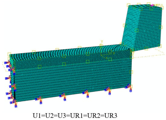
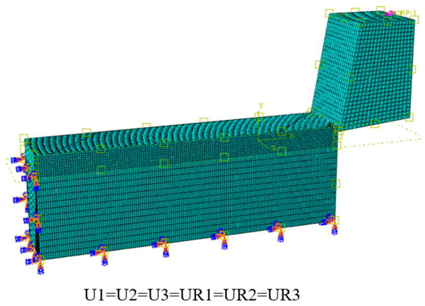
Mesh quality directly affects computational accuracy and efficiency. In this study, the element type was defined as a linear explicit temperature–displacement coupled element. Fine seed meshes were generated in the cutting region ahead of the tool and along the chip formation path, while coarser meshes were adopted in the workpiece regions far from the cutting zone to reduce the computational cost. Both the workpiece and cutting tool were meshed as an 8-node thermally coupled brick(C3D8RT), using three-direction linear displacement and trilinear displacement and temperature, reduced integration, and default hourglass control. The machined workpiece consisted of 112,344 nodes and 103,500 elements, and the cutting tool consisted of 8748 nodes and 7514 elements. For the workpiece, a local mesh refinement was adopted in the cutting region, as highlighted in Figure 1. The refined cutting region was defined with a height of 10 mm, corresponding to approximately one-fifth of the total workpiece volume. As shown in Figure 1, the mesh size in this refined region was set to 0.01 mm [26], while a coarser mesh size of 0.03 mm was used in the non-cutting region to reduce computational cost. The mesh size of the cutting tool was set to 0.02 mm, ensuring a clear distinction from the refined cutting region and facilitating the subsequent cutting simulation.
Figure 1.
Load and mesh settings of the model.
3.4. Definition of Contact and Boundary Conditions
Surface-to-surface contact was defined between the cutting tool and the workpiece. The contact algorithm was based on the penalty method, and the frictional behavior was assumed to follow the Coulomb friction model.
The interaction between the cutting tool and the workpiece was defined using a surface-to-surface contact algorithm, and the friction model was implemented using the penalty contact method. Based on relevant literature, and considering the frictional characteristics of polyethylene-based materials, the friction coefficient was set to 0.25 [22]. In addition, general self-contact was defined to prevent model penetration during the simulation.
To simulate the clamping condition of the workpiece during the actual cutting process, fixed constraints were applied to the bottom and side surfaces of the workpiece, which are also shown in Figure 1. The cutting motion was simulated by defining the tool as an analytical rigid body through a fixed reference point and applying a constant horizontal velocity, Vc, to the reference point of the tool.
3.5. Thermo-Mechanical Coupled Finite Element Simulation Process
During the cutting process, plastic deformation of PE and friction at the tool–workpiece interface generate a considerable amount of heat, leading to a localized temperature rise in the cutting region. Therefore, thermo-mechanical coupling was considered in the numerical simulation. Among the heat sources, part of the plastic work generated by material deformation is converted into thermal energy. The heat generation rate due to plastic deformation can be expressed as:
where is the heat generation rate per unit volume due to plastic deformation, ηp is the plastic-work-to-heat conversion coefficient, σeq is the von Mises equivalent stress, and is the equivalent plastic strain rate.
The temperature field during PE cutting is jointly governed by internal heat conduction, heat generated by plastic deformation, and frictional heat at the tool–workpiece interface. In the thermo-mechanically coupled analysis, the governing equation of the temperature field can be expressed as:
where ρ is the material density, c is the specific heat capacity, T is the temperature, t is the time, k is the thermal conductivity, is the heat source term associated with plastic deformation, and is the frictional heat source term. This equation indicates that the variation in cutting temperature depends not only on heat generation but also on the thermal conductivity of the material.
During the contact between the cutting tool and the PE workpiece, heat transfer also occurs across the interface. The heat flux density at the contact interface can be expressed as:
where qc is the heat flux density at the contact interface, hc is the interfacial thermal conductance coefficient, Tt is the temperature of the tool contact surface, and Tw is the temperature of the PE workpiece contact surface.
qc = hc(Tt − Tw)
Due to the relatively low thermal conductivity of PE, the cutting heat is difficult to dissipate rapidly within a short period of time, which can easily lead to localized heat accumulation. Therefore, a thermal conductance coefficient was assigned at the contact interface in the Interaction module, to simulate heat transfer between the cutting tool and the workpiece. In addition, the plastic-work-to-heat conversion coefficient was introduced to account for the heat generated by internal plastic deformation during the cutting process.
The initial temperature of the model was set to 25 °C, representing the initial cutting condition at room temperature.
4. Validation of the Cutting Model
The predicted cutting force and chip-formation characteristics were compared with previously reported experimental results to evaluate the reliability of the established finite element model [18,27].
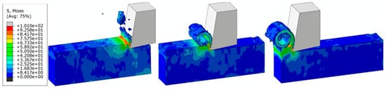
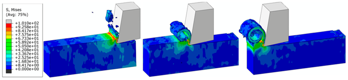
Figure 2 presents the stress contour plot of the cutting stress field at Vc = 500 mm/s and ac = 7 mm [26]. To clearly illustrate the evolution of the orthogonal cutting process, three representative key frames corresponding to the initial stage, intermediate stage, and final stage of cutting were selected.
Figure 2.
Equivalent stress contour plot of polyethylene cutting process.
The experimental and numerical results reported by Kaddeche et al. [27] and Yang et al. [22] were selected for comparison. HDPE is a semicrystalline grade within the polyethylene family and shares several fundamental characteristics with the non-cross-linked PE considered in the present study, including thermoplastic behavior, temperature sensitivity, and strain-rate-dependent deformation. Therefore, HDPE machining data can provide a useful external reference for evaluating the general cutting response of the present model. However, different PE grades may differ in molecular branching, crystallinity, density, stiffness, and strength, resulting in differences in their cutting resistance and thermal response. Such material differences should therefore be considered as one possible source of deviation between the present simulation and the reference experimental results.
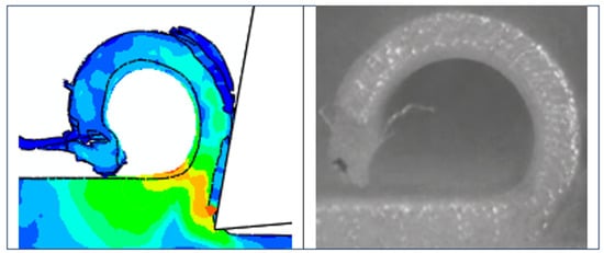
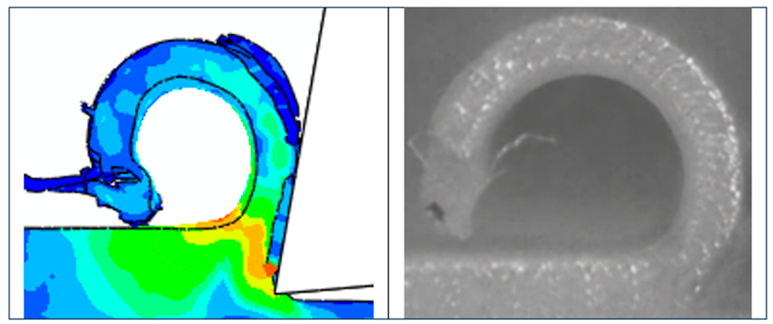
In the present study, cutting behavior is consistent with the chip formation mechanism reported by Yang et al, as shown in Figure 3. Therefore, although direct quantitative comparison is limited by differences, the agreement in cutting-force trend and chip formation characteristics supports the validity of the proposed thermo-mechanically coupled orthogonal cutting model for PE materials.
Figure 3.
Chip morphology comparison against Yang’s experiment [22].
To provide a quantitative comparison, the average main cutting force obtained from the present simulation was compared with the experimental cutting force reported in the literature.
The average cutting force was calculated from the time-varying cutting force history using the following expression:
where is the average cutting force, |RF1(t)| is the reaction force of the tool reference point in the cutting direction, and t1 and t2 represent the selected time interval for evaluating the cutting force.
Table 2 presents the simulated cutting forces of 66.15 N and 69.99 N at cutting speeds of 57 m/min (950 mm/s) and 114 m/min (1900 mm/s), respectively, with a fixed cutting depth of 2 mm. Compared with the corresponding experimental values of 79.52 N and 75.74 N, the relative errors were 16.81% and 7.59%, respectively.
Table 2.
Comparison of simulated cutting forces with the experimental data reported by Kaddeche et al. [27].
The deviations between the simulated and experimental cutting forces may be attributed to several factors. First, differences in the mechanical properties of PE and HDPE, particularly their strain-rate sensitivity and temperature-dependent deformation behavior, may influence the cutting resistance. Second, the reference experiments were conducted under turning conditions, whereas the present study employed an idealized orthogonal cutting model. Differences in cutting geometry and tool configuration may therefore affect the cutting-force results. Furthermore, the use of a constant Coulomb friction coefficient and simplified constitutive and damage formulations may introduce additional deviations, as also discussed in previous studies on polymer machining.
Nevertheless, despite the relatively large maximum relative error, the simulated cutting forces remain comparable in magnitude to the experimental results. In addition, the simulated chip formation characteristics exhibit qualitative agreement with those reported in previous studies [22,28]. Considering the differences in material properties, cutting conditions, and numerical modeling assumptions, the agreement in cutting-force magnitude and chip formation behavior provides reasonable support for the validity of the established finite element model. Therefore, although certain quantitative deviations remain, the model is considered capable of reasonably reproducing the main mechanical characteristics of PE orthogonal cutting and provides a reliable basis for investigating the relative effects of cutting parameters on cutting force and chip formation. It should be noted that the temperature results are only simulation predictions and have not yet been quantitatively validated by experiments.
5. Single-Factor Experimental Results and Discussion of Cutting Parameters
To investigate the influence of cutting parameters on the orthogonal cutting behavior of PE, a single-factor simulation scheme was adopted in this study. Single-factor parameter analysis is commonly used to clarify the dominant influence of individual cutting parameters. Similar unifactorial approaches have been employed in previous polyethylene machining studies to isolate the influence of individual cutting parameters [27]. Therefore, the present work focuses on the first-order influence of the two main cutting parameters rather than their cross-interaction.
Two groups of cutting simulations were designed. In the first group, the cutting depth was fixed at 5 and 7 mm, and the cutting speed was varied as 100, 200, 500, 750, and 1000 mm/s to analyze the influence of cutting speed. In the second group, the cutting speed was fixed at 500 mm/s, and the cutting depth was varied as 1, 2, 5, and 7 mm to analyze the influence of cutting depth.
Through this parameter setting, the independent effects of cutting speed and cutting depth on cutting force, cutting temperature, stress distribution, and chip formation behavior were evaluated. The value ranges of the cutting speed and cutting depth are shown in Table 3.
Table 3.
Values of single-factor process parameters.
5.1. Influence of Cutting Speed on Cutting Temperature and Cutting Force
The simulation results obtained using the single-factor parameters listed in Table 3 are presented below.
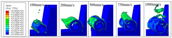
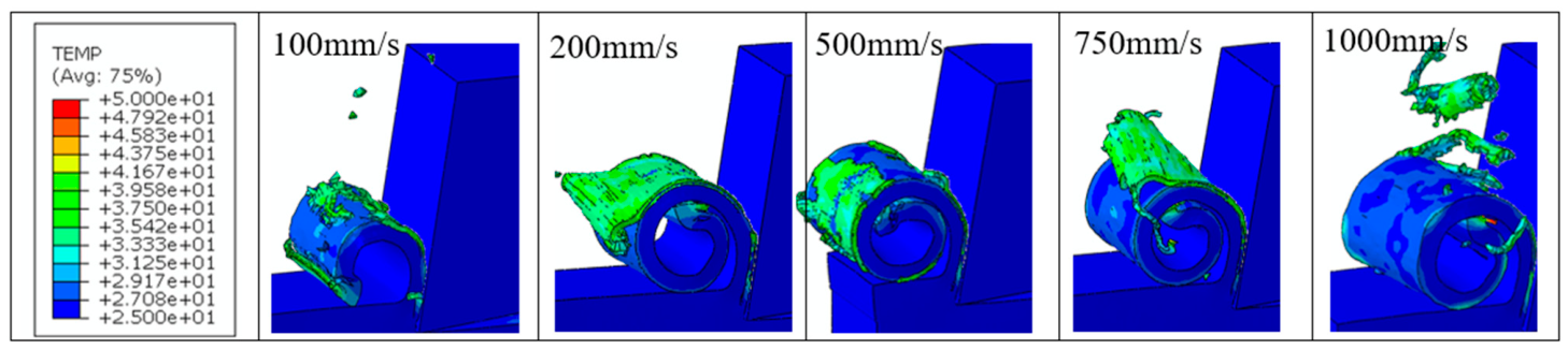
Figure 4 shows the temperature field distributions under different cutting speed conditions. As can be observed from the figures, the temperature in the cutting region exhibits an obvious localized concentration under all cutting speed conditions. The high-temperature regions are mainly located near the rake face of the tool, the chip root, and the curled chip region. These regions correspond to the areas where tool extrusion, material shear deformation, and interfacial friction are most intense, and thus represent the main zones of cutting heat generation. The temperature variation in the main body of the workpiece away from the cutting zone is relatively small, indicating that the cutting heat is mainly concentrated in the local cutting region within a short period and has not fully diffused throughout the entire workpiece. Most regions of the workpiece remain close to the initial temperature, while the cutting heat is mainly concentrated in the tool–workpiece contact zone and the chip formation zone. When the cutting speed reaches 1000 mm/s, the peak temperature appears, with a maximum temperature of 71.93 °C.
Figure 4.
Temperature contours at different cutting speeds at a cutting depth of 7 mm.
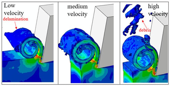
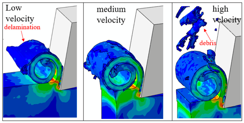
From the perspective of cutting speed, when the cutting speed is relatively low, the interaction between the tool and the material is mainly dominated by extrusion and slow shear deformation. Under this condition, the temperature rise in the cutting zone is limited, and thermal softening of the material is not significant. The stress concentration ahead of the tool tip is relatively dispersed, and the cutting layer undergoes a longer period of compressive deformation before material separation. As a result, the chip is relatively thick, with a weak curling tendency, indicating insufficient material flow. Figure 5 shows the chip morphology under low, medium, and high cutting speeds. As the cutting speed increases, the relative sliding velocity at the tool–chip interface increases, and frictional heat together with plastic deformation heat accumulates rapidly near the chip root. This promotes thermal softening of the material. With the reduction in material flow resistance, the chip can be discharged more continuously along the rake face, the primary shear zone becomes more distinct, and the chip separation process becomes more stable. Therefore, at a moderate cutting speed, the strip-like chip morphology is more complete, and the chip curling and discharge process becomes more evident.
Figure 5.
Representative chip morphologies at low, medium, and high cutting speeds at a cutting depth of 7 mm.
When the cutting speed further increases, chip formation is jointly affected by thermal softening, strain-rate effects, and dynamic contact fluctuations. On the one hand, higher cutting speed increases the local temperature, which promotes material softening and accelerates damage evolution. On the other hand, PE is sensitive to strain rate, and a higher deformation rate may enhance the instantaneous deformation resistance of the material. In addition, high-speed contact between the tool and the chip can induce local stress fluctuations, making the damage propagation near the chip root less stable. Therefore, under high-speed cutting conditions, the chip still appears in a strip-like form; however, obvious local accumulation occurs, and partial separation can be observed during chip discharge. Under this condition, the cutting force may also show a certain rebound. The chip formation process can therefore be considered to be jointly controlled by thermal softening and strain-rate strengthening effects.
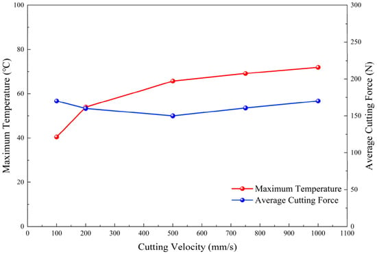
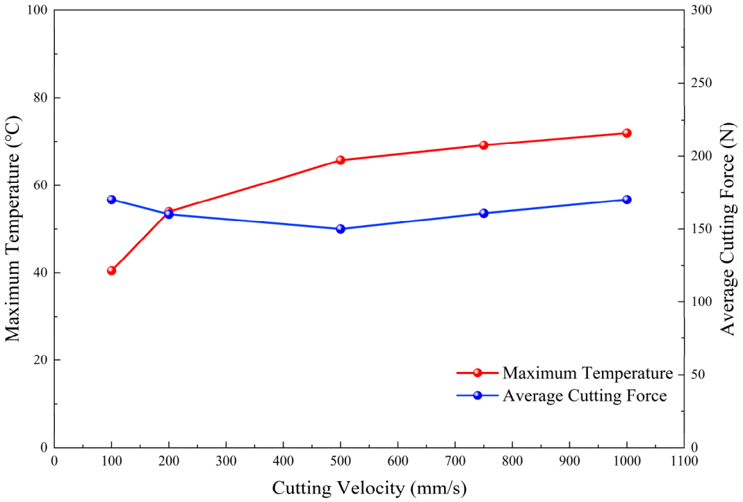
Figure 6 shows the variations in maximum cutting temperature and average cutting force with cutting speed. The simulation results show that, with increased cutting speed, the peak temperature generally exhibits a gradual upward trend. When the cutting speed increases from 100 mm/s to 1000 mm/s, the maximum temperature rises from approximately 40 °C to 72 °C. This is because an increase in cutting speed leads to a higher material shear deformation rate and a higher frictional sliding velocity between the tool and the material, thereby increasing the shear heat and frictional heat generated per unit time. Owing to the relatively high specific heat capacity and low thermal conductivity of PE, the temperature variation remains within a relatively reasonable range.
Figure 6.
Maximum cutting temperature and average cutting force as functions of cutting speed at a cutting depth of 7 mm.
With the increase in cutting speed, the main cutting force generally shows a trend of first decreasing and then slightly increasing. When the cutting speed increases from 100 mm/s to 500 mm/s, the main cutting force decreases from approximately 170 N to 150 N. This decrease can be mainly attributed to the increase in cutting temperature and the resulting thermal softening of PE. As more frictional heat and plastic deformation heat are generated in the cutting zone, the local shear strength of the material decreases, and the resistance to material removal is reduced. In addition, the ploughing effect at relatively low cutting speed is weakened as the cutting process becomes more continuous, which also contributes to the reduction in cutting force.
However, when the cutting speed further increases to 1000 mm/s, the average cutting force increases again. This turning point may be related to the enhanced strain-rate effect of PE at higher cutting speeds. As the deformation rate in the cutting zone increases, the viscoelastic relaxation of PE becomes more restricted, and the material exhibits greater instantaneous resistance to deformation. Meanwhile, the inertial effect of the material and the tool-workpiece impact interaction during chip formation become more significant. Therefore, although thermal softening still occurs, the combined effects of strain-rate strengthening, inertia, and contact interaction lead to the slight increase in the main cutting force at 1000 mm/s [29].
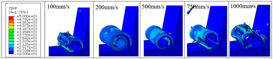
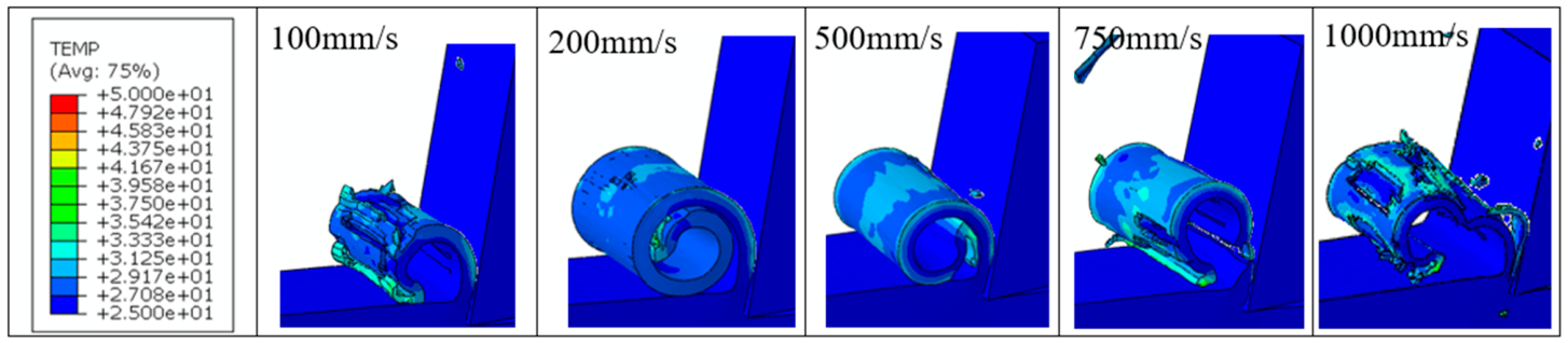
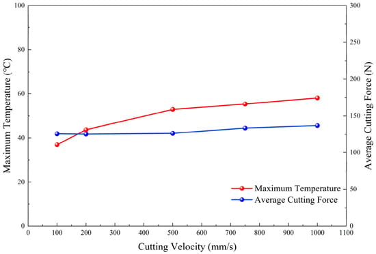
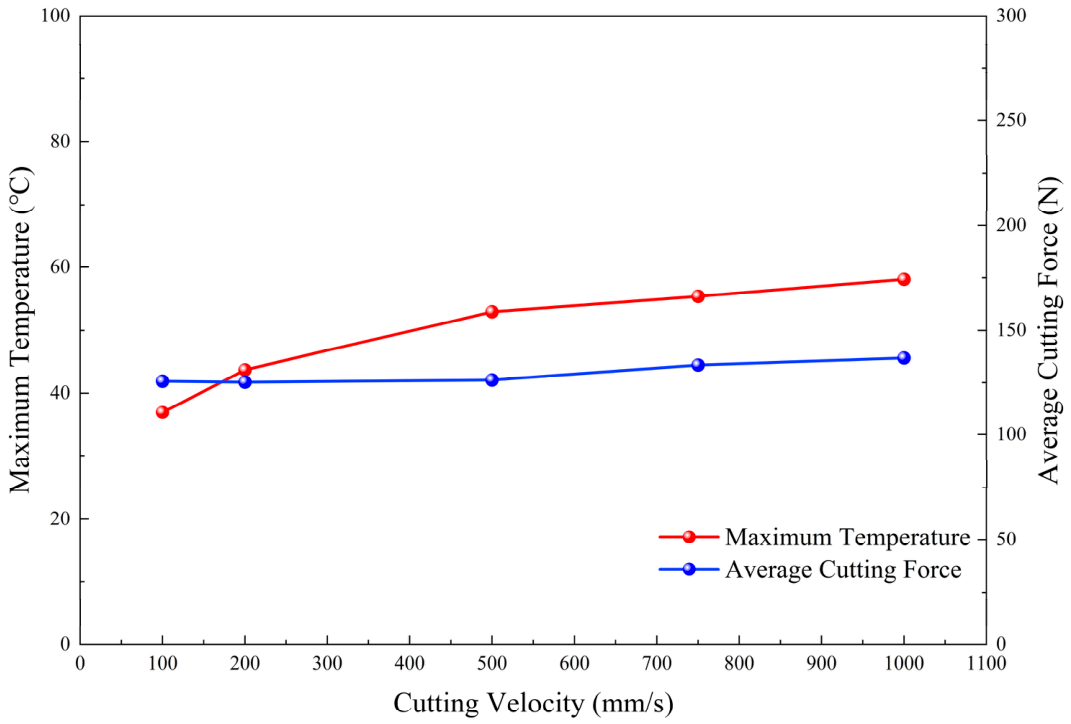
As shown in Figure 7 and Figure 8, at a constant cutting depth of 5 mm, the maximum cutting temperature increases continuously with cutting speed. As the cutting speed increases from 100 mm/s to 1000 mm/s, the maximum temperature rises from approximately 37.0 °C to 58.1 °C. The temperature field remains highly localized around the chip root and the tool–chip contact region, while most of the workpiece remains close to the initial temperature. Compared with the 7 mm cutting-depth condition, the overall temperature level is noticeably lower. This difference is mainly attributed to the smaller volume of material undergoing severe deformation and the reduced tool–chip contact region at the lower cutting depth, which decrease the total heat generated and accumulated in the cutting zone.
Figure 7.
Temperature contours at cutting speeds of 100, 200, 500, 750, and 1000 mm/s at a cutting depth of 5 mm.
Figure 8.
Maximum cutting temperature and average cutting force as functions of cutting speed at a cutting depth of 5 mm.
The chip morphology also exhibits a relatively stable evolution at low and moderate cutting speeds. Under the 5 mm cutting-depth condition, the reduced material removal volume results in a smaller chip cross-section and less pronounced material accumulation than that observed at 7 mm. As the cutting speed increases, chip curling becomes more evident and the material is discharged along the rake face more continuously. At higher cutting speeds, particularly at 750 and 1000 mm/s, local fluctuations and partial separation of the curled chip become more apparent, indicating an increased influence of the dynamic deformation response of PE.
A different cutting-force response is observed compared with the 7 mm cutting-depth condition. Between 100 and 500 mm/s, the average cutting force remains nearly unchanged, varying only from approximately 125.6 N at 100 mm/s to 125.3 N at 200 mm/s and 126.2 N at 500 mm/s. The limited variation indicates that neither thermal softening nor strain-rate strengthening dominates the material response within this speed range. In particular, because the heat generated at a cutting depth of 5 mm is lower than that at 7 mm, the thermal-softening effect is insufficient to produce the pronounced reduction in cutting force observed under the larger cutting-depth condition.
When the cutting speed increases beyond 500 mm/s, the average cutting force rises markedly, reaching approximately 133.2 N at 750 mm/s and 136.6 N at 1000 mm/s. At these higher speeds, the deformation time available for viscoelastic relaxation becomes shorter and the strain-rate-dependent resistance of PE becomes increasingly significant. Since the temperature rise under the 5 mm condition remains relatively limited, thermal softening is no longer sufficient to compensate for this increase in deformation resistance. Consequently, strain-rate strengthening gradually becomes the dominant factor, resulting in the pronounced increase in cutting force above 500 mm/s. Dynamic tool–chip interaction and material inertia further contribute to this increase at the highest cutting speeds.
The predicted influence of cutting speed is supported by previous studies on polyethylene machining and mechanical behavior. Kaddeche et al. [27] reported that increasing cutting speed during HDPE machining resulted in a gradual reduction in the cutting-force components, accompanied by an increase in interface temperature and enhanced material softening. This observation is consistent with the reduction or relatively stable cutting-force response obtained at low-to-moderate cutting speeds in the present simulations. In addition, experimental studies on semicrystalline polyethylene have demonstrated that PE materials exhibit both temperature-softening and strain-rate-strengthening effects [23]. Therefore, the subsequent increase in cutting force at higher cutting speeds in the present study can be reasonably interpreted as an increasing contribution of strain-rate-dependent deformation resistance as the cutting speed increases.
5.2. Influence of Cutting Depth on Cutting Temperature and Cutting Force
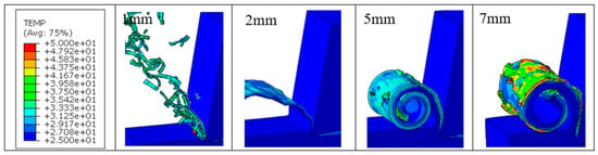
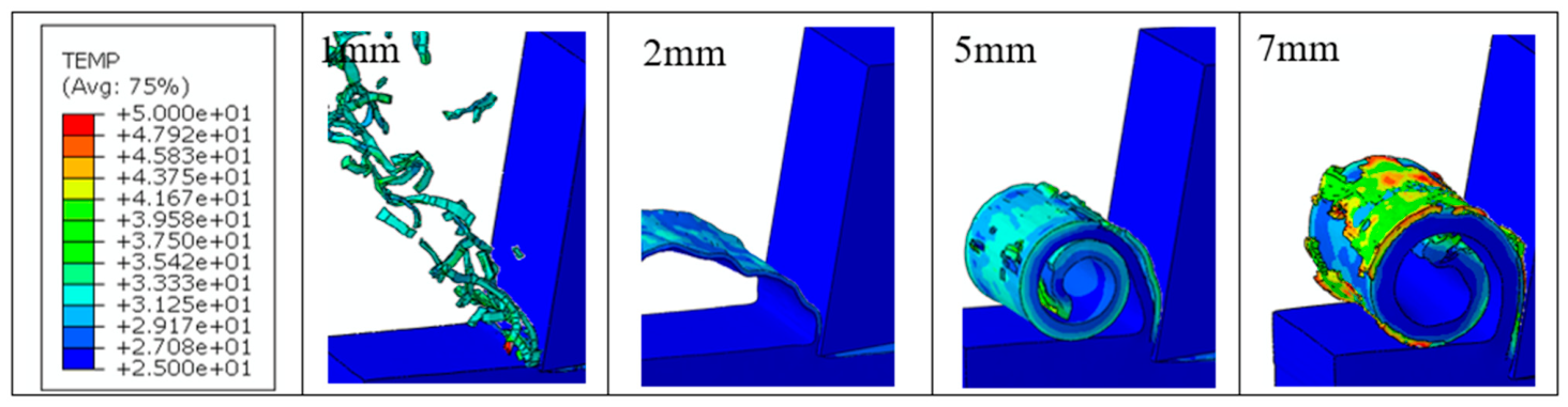
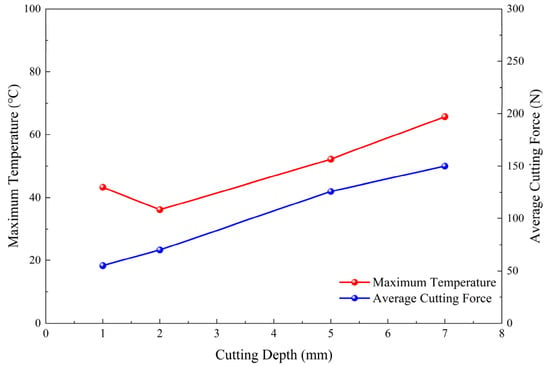
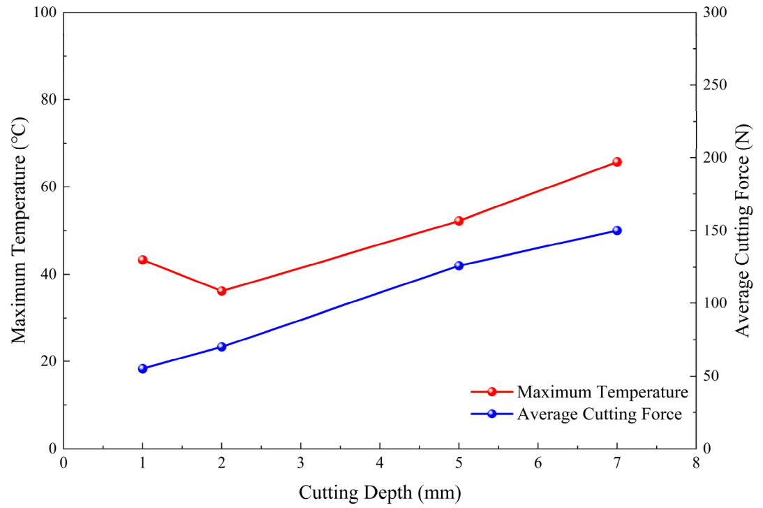
Figure 9, Figure 10 and Figure 11 show the temperature field distributions under different cutting depth conditions. For all cases, the cutting temperature exhibits a clear localized concentration, while most regions of the workpiece remain close to the initial temperature. This indicates that the cutting heat is mainly confined to the local cutting zone.
Figure 9.
Temperature contours at cutting depths of 1, 2, 5, and 7 mm at a cutting speed of 500 mm/s.
Figure 10.
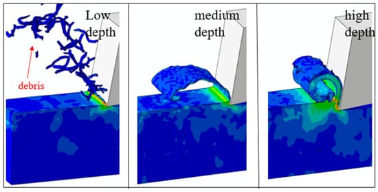
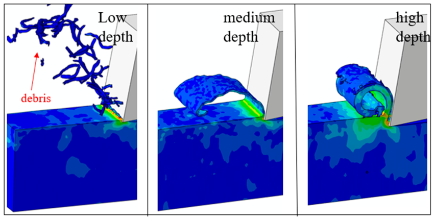
Representative chip morphologies at low, medium, and high cutting depths at a cutting speed of 500 mm/s.
Figure 11.
Maximum cutting temperature and average cutting force as functions of cutting depth at a cutting speed of 500 mm/s.
In terms of peak temperature, the maximum values are approximately 43.11 °C, 36.14 °C, 52.98 °C, and 66.65 °C at cutting depths of 1 mm, 2 mm, 5 mm, and 7 mm, respectively.
The influence of cutting depth on chip morphology is directly reflected in the variation in the undeformed chip thickness and length of tool–chip contact area. When the cutting depth is 1 mm, the volume of material involved in cutting is relatively small, and the primary shear zone is limited. Under this condition, the chip is thin, and the stress concentration at the chip root is mainly confined to the region near the tool tip. Owing to the small thickness of the cutting layer, extrusion and ploughing account for a relatively large proportion of the material separation process, resulting in weak chip continuity and limited chip curling.
When the cutting depth increases to 2 mm and 5 mm, the undeformed chip thickness increases, and the volume of material undergoing plastic deformation and damage separation ahead of the tool also increases. As a result, the primary shear zone gradually expands. The chip thickness increases, and the contact length between the rake face and the chip becomes longer, leading to further accumulation of interfacial friction heat and plastic deformation heat. Consequently, the chip root becomes a region where stress, strain, and temperature are simultaneously concentrated. At moderate cutting depths, the chip separation process is more stable, and the strip-like chip morphology becomes more pronounced.
When the cutting depth further increases to 7 mm, the cross-sectional area of the cutting layer and the tool–chip contact length increase significantly, leading to higher plastic deformation energy and damage energy required for material separation. In this case, the primary shear zone expands further, and both the chip thickness and bending stiffness increase markedly. Under the constraint and friction of the rake face, thicker strip-like or curled strip-like chips are more likely to form. Meanwhile, a larger cutting depth increases cutting resistance and may obstruct chip discharge, causing separation and fluctuations during the chip removal process.
As the cutting depth increases, the temperature in the cutting zone generally exhibits an increasing trend. In particular, at cutting depths of 5 and 7 mm, the temperature rise becomes more pronounced, indicating that a larger cutting depth significantly enhances the thermal accumulation effect in the cutting zone. However, it can also be observed that the peak temperature under the 2 mm condition is lower than that under the 1 mm condition, showing a certain degree of local fluctuation.
As the cutting depth increases from 1 mm to 2 mm, the chip formation mode changes from fragmented and discontinuous chip formation to a relatively stable and continuous process, as illustrated in Figure 10. At a cutting depth of 1 mm, repeated chip fracture causes intermittent tool–chip contact, concentrating plastic-deformation and frictional heat near the tool tip and producing pronounced temperature and cutting-force fluctuations. Previous studies on polymer and polymer-based material machining have shown that part of the heat generated during cutting can be carried away by the removed chips. Therefore, the lower peak temperature observed at 2 mm is associated with changes in chip formation and transient heat partition between the chip, tool, and workpiece [30]. At 2 mm, the more stable chip formation promotes a continuous material-removal process and allows a greater proportion of the generated heat to be carried away by the chip. Consequently, the maximum cutting temperature decreases from approximately 43.11 °C at 1 mm to 36.14 °C at 2 mm. Nevertheless, the average cutting force increases because the larger undeformed chip thickness and tool–chip contact area increase the resistance to material removal, although the force fluctuation becomes less pronounced. When the cutting depth further increases to 5 and 7 mm, the enlarged deformation zone and extended tool–chip contact generate substantially more plastic-deformation heat and frictional heat, resulting in a marked increase in both cutting temperature and cutting force.
As the cutting depth increased from 1 mm to 7 mm, the average main cutting force increases from approximately 55 N to 150 N, generally showing a gradual upward trend with increasing cutting depth, while the growth rate gradually decreased. This indicates that PE has a strong plastic deformation capacity during cutting, which contributes to the continuous increase in cutting force as the cutting depth increases.
Under larger cutting depths of 5–7 mm, the fluctuation amplitude of the main cutting force increases significantly, and the maximum cutting force reaches approximately 250 N. This suggests that, as the cutting depth increases, the contact area between the tool and the material expands and the material removal volume increases, leading to a significant increase in cutting load.
The predicted influence of cutting depth is supported by previously reported polyethylene machining studies in terms of both mechanical and thermal responses. A similar dependence was also observed for the thermal response. Kaddeche et al. [27] reported that the measured cutting-zone temperature increased with depth of cut, with relatively moderate variations at smaller depths and a much more pronounced temperature rise at the largest investigated depth. This behavior is consistent with the present simulations, in which the increase in cutting temperature becomes particularly evident at cutting depths of 5 and 7 mm. Mechanistically, a larger cutting depth increases the undeformed chip thickness, the volume of material undergoing deformation and separation, and the extent of tool–chip contact. Consequently, both the mechanical resistance to material removal and the heat generated by plastic deformation and interfacial friction increase. The simultaneous increase in cutting force, cutting temperature, chip thickness, and tool–chip contact length predicted in the present study is therefore consistent with the cutting-depth-dependent behavior reported in previous polyethylene machining investigations [21,27].
In summary, cutting speed has a positive effect on cutting temperature, while the main cutting force generally shows a trend of first decreasing and then slightly increasing with increasing cutting speed. The accumulation of cutting heat is the primary cause of temperature rise, while the strain-rate sensitivity of the viscoelastic PE material leads to a significant increase in cutting force as the cutting speed increases. Cutting depth is also positively correlated with cutting temperature and cutting force; however, its influence exhibits different characteristics. The temperature increases with cutting depth but shows a gradually decreasing growth rate, whereas the cutting force presents a relatively steady upward trend. During the cutting of PE, material fragmentation and chip formation remove a large amount of heat, which is a key factor contributing to the fluctuation in the maximum temperature.
6. Conclusions
- (1)
- In this study, a three-dimensional thermo-mechanically coupled finite element model was established for the cutting process of PE structural components. The progressive constitutive model and progressive damage model were adopted to describe the mechanical behavior of the material, thereby realizing the numerical simulation of the PE orthogonal cutting process.
- (2)
- The validity of the established numerical model was assessed by comparing the predicted cutting force and chip-formation characteristics with available experimental results. The simulation results showed reasonable agreement with the experimental observations in terms of their cutting force and chip formation features, indicating that the model can reasonably reproduce the basic thermo-mechanical response of PE materials during cutting.
- (3)
- Cutting speed has a relatively significant influence on the stress distribution, temperature field, and cutting force. As the cutting speed increases, the maximum cutting temperature generally increases due to the enhanced plastic deformation and frictional heat generation in the cutting zone. The main cutting force generally shows a variation in first decreasing or remaining relatively stable at low-to-moderate cutting speeds and then increasing at higher cutting speeds. This behavior is mainly associated with the competing effects of thermal softening and strain-rate strengthening of PE. The influence of cutting speed on the cutting force becomes more pronounced under larger cutting depths.
- (4)
- With increasing cutting depth, both cutting temperature and cutting force generally show an upward trend. Under larger cutting depths, the fluctuation amplitude of the cutting force increases significantly, and the maximum cutting force can reach approximately 250 N.
The research results clarify the influence laws and underlying mechanisms of single-factor cutting parameters on the cutting performance of PE, and can provide a theoretical basis and data support for optimizing cutting process parameters and improving the machining performance of PE structural components.
Author Contributions
Q.G.: Writing—review & editing, software, project administration, methodology, visualization. Y.C.: Methodology, funding acquisition, investigation, supervision. D.L.: Data curation, project administration. W.S.: Resources, visualization. J.Y.: Writing—review & editing, methodology. H.L.: Writing—editing, data curation, validation. X.W.: Conceptualization, supervision, funding acquisition. Y.Z.: Project administration, supervision, writing—review & editing. All authors have read and agreed to the published version of the manuscript.
Funding
This research was funded by the Research Funds of Guangdong Power Grid Co. Ltd., (Grant No. GDKJXM20240661), the Fundamental Research Funds for the Central Universities (Grant No. 25CX06067A and No. 26CX02012A), the National Natural Science Foundation of China (Grant No. 52505502 and No. 52305521), the Shandong Provincial Natural Science Foundation (Grant No. ZR2024QE205 and No. ZR2024QE277), and the National Natural Science Foundation of China (Grant No. 52474176).
Data Availability Statement
The original contributions presented in this study are included in the article. Further inquiries can be directed to the corresponding author.
Acknowledgments
The authors wish to thank the anonymous reviewers for their comments which led to improvements of this paper.
Conflicts of Interest
Authors Qidi Guo, Yun Chen, Duanjiao Li, Wenxing Sun and Junwen Yao were employed by the company Guangdong Power Grid Co., Ltd. The remaining authors declare that the research was conducted in the absence of any commercial or financial relationships that could be construed as a potential conflict of interest.
References
- Sun, B.; Pang, W.; Chen, M.; Zhu, D. Development and experimental verification of search and rescue ROV. Intell. Robot. 2022, 2, 355–370. [Google Scholar] [CrossRef] [Scilit]
- Zhang, W.; Zhu, K.; Yang, Z.; Ye, Y.; Ding, J.; Gan, J. Development of an Underwater Detection Robot for the Structures with Pile Foundation. J. Mar. Sci. Eng. 2024, 12, 1051. [Google Scholar] [CrossRef] [Scilit]
- Yang, C.; Zhang, J.; Yue, H.; Kang, X. The Low Friction Coefficient and High Wear Resistance UHMWPE: The Effect of Pores on Properties of Artificial Joint Materials. Lubricants 2025, 13, 31. [Google Scholar] [CrossRef] [Scilit]
- Nisazarifa, A.; Nursyifaulkhair, D.; Rosalina, A.; Wibawa, I.P.A.; Saputra, M.R.A. Sustainable Boatbuilding: Evaluating the Feasibility of Recycled HDPE as a Structural Material. BIO Web Conf. 2026, 216, 05001. [Google Scholar] [CrossRef] [Scilit]
- Zhao, X.; Jin, S.; Bian, G.; Cui, Y.; Wang, J.; Tang, Y.; Jiang, C. Technical Design and Data Analysis of Autonomous Underwater Vehicle-Based Side-Scan Sonar Operations. J. Mar. Sci. Eng. 2023, 11, 2089. [Google Scholar] [CrossRef] [Scilit]
- Patel, K.; Chikkali, S.H.; Sivaram, S. Ultrahigh molecular weight polyethylene: Catalysis, structure, properties, processing and applications. Prog. Polym. Sci. 2020, 109, 101290. [Google Scholar] [CrossRef] [Scilit]
- He, G.; Zhang, W.; Sun, K.; Qi, J.; Zhao, J.; Han, J.; Zhu, X. The impact of XLPE surface defects on electric field and breakdown voltage. Front. Energy Res. 2024, 12, 1476046. [Google Scholar] [CrossRef] [Scilit]
- Liu, Z.Y.; Bian, Y.L.; Cai, Y.; Wang, N.; Wang, W.Z.; Bie, B.X.; Li, B.; Hua, J.Y.; Luo, S.N. High-speed penetration of ultra-high molecular weight polyethylene plates: Experiments and modeling. Eur. J. Mech. A/Solids 2026, 115, 105783. [Google Scholar] [CrossRef] [Scilit]
- Mammeri, S.; Chaoui, K.; Bouacha, K. Manufacturing of testing specimens from tough HDPE-100 pipe: Turning parameters optimization. Res. Eng. Struct. Mater. 2024, 10, 513–536. [Google Scholar] [CrossRef] [Scilit]
- Costa, D.D.d.; Corrêa, H.L.; Rebeyka, C.J.; Zawadzki, S.F. UHMWPE molecular structure analysis after turning operations and machinability with a standard off-the-shelf carbide tool. Eng. Res. Express 2019, 1, 025039. [Google Scholar] [CrossRef] [Scilit]
- Wu, Z.; Wang, J.; Yuan, X.; Guo, X.; Zhu, Z.; Zhang, F.; Cao, P. Research on the orthogonal cutting performance of polyethylene-based wood-plastic composite based on principal component analysis. Eur. J. Wood Wood Prod. 2022, 81, 591–603. [Google Scholar] [CrossRef] [Scilit]
- Hamlaoui, N.; Azzouz, S.; Chaoui, K.; Azari, Z.; Yallese, M.A. Machining of tough polyethylene pipe material: Surface roughness and cutting temperature optimization. Int. J. Adv. Manuf. Technol. 2017, 92, 2231–2245. [Google Scholar] [CrossRef] [Scilit]
- Guo, Z.E.; Luo, Y. Cutting Performance Analysis of Carbon Fiber Reinforced Polyethylene Composites. HENAN Chem. Ind. 2020, 37, 22–25. [Google Scholar]
- Cao, X.; Wu, X.; Meng, X.; Zhang, S.; Song, T.; Ren, P.; Li, T. Numerical Simulation and Experimental Validation of Cutting Mechanism of Carbon Fiber-Reinforced Thermoplastic Composites. Polymers 2026, 18, 464. [Google Scholar] [CrossRef] [Scilit]
- Cepero-Mejías, F.; Curiel-Sosa, J.; Zhang, C.; Phadnis, V. Effect of cutter geometry on machining induced damage in orthogonal cutting of UD polymer composites: FE study. Compos. Struct. 2019, 214, 439–450. [Google Scholar] [CrossRef] [Scilit]
- Xiaonan, W. Scheme Research on Insulation Shield Stripping System of 110 kV Single Core Cable Joint. Master’s Thesis, North China Electric Power University, Beijing, China, 2024. [Google Scholar]
- Zhang, Y.; Wu, Z.; Qian, C.; Tan, X.; Yang, J.; Zhong, L. Research on Lifespan Prediction of Cross-Linked Polyethylene Material for XLPE Cables. Appl. Sci. 2020, 10, 5381. [Google Scholar] [CrossRef] [Scilit]
- Li, F.; Zhao, Y.; Zhang, C. Theoretical analysis and numerical simulation of cable turning and stripping process. Sci. Technol. Eng. 2022, 22, 11097–11104. [Google Scholar]
- Spanu, P.; Abaza, B.F.; Constantinescu, T.C. Analysis and prediction of temperature using an artificial neural network model for milling glass fiber reinforced polymer composites. Polymers 2024, 16, 3283. [Google Scholar] [CrossRef] [Scilit]
- Elgnemi, T.; Songmene, V.; Kouam, J.; Jun, M.B.; Samuel, A.M. Experimental investigation on dry routing of CFRP composite: Temperature, forces, tool wear, and fine dust emission. Materials 2021, 14, 5697. [Google Scholar] [CrossRef] [Scilit]
- Guo, X.; Wang, J.; Buck, D.; Zhu, Z.; Guo, Y. Machinability of wood fiber/polyethylene composite during orthogonal cutting. Wood Sci. Technol. 2021, 55, 521–534. [Google Scholar] [CrossRef] [Scilit]
- Yang, B.; Wang, H.; Fu, K.; Wang, C. Prediction of Cutting Force and Chip Formation from the True Stress–Strain Relation Using an Explicit FEM for Polymer Machining. Polymers 2022, 14, 189. [Google Scholar] [CrossRef] [Scilit]
- Alhourani, A.; Barsoum, I.; Sheikh-Ahmad, J.; Deveci, S. Development of Johnson Cook plasticity and damage model parameters for the time-dependent behavior of high-density polyethylene. In Proceedings of the World Congress on Mechanical, Chemical, and Material Engineering; Avestia Publishing: Ottawa, ON, Canada, 2024. [Google Scholar]
- Zhang, K.; Li, W.; Zheng, Y.; Yao, W.; Zhao, C. Dynamic constitutive model of ultra-high molecular weight polyethylene (UHMWPE): Considering the temperature and strain rate effects. Polymers 2020, 12, 1561. [Google Scholar] [CrossRef] [Scilit]
- Ciecieląg, K.; Kawalec, A.; Gdula, M.; Żurek, P. Modeling and Cutting Mechanics in the Milling of Polymer Matrix Composites. Materials 2025, 18, 3017. [Google Scholar] [CrossRef] [Scilit]
- An, Q.; Zhang, J.; Xiao, G.; Xu, C.; Yi, M.; Chen, Z.; Chen, H.; Zheng, C.; Li, G. Fiber Orientation Effects in CFRP Milling: Multiscale Characterization of Cutting Dynamics, Surface Integrity, and Damage Mechanisms. J. Compos. Sci. 2025, 9, 342. [Google Scholar] [CrossRef] [Scilit]
- Kaddeche, M.; Chaoui, K.; Yallese, M.A. Cutting parameters effects on the machining of two high density polyethylene pipes resins. Mech. Ind. 2012, 13, 307–316. [Google Scholar] [CrossRef] [Scilit]
- Wang, W.; Specketer, H.; Langenhorst, L.; Riemer, O.; Rickens, K.; Karpuschewski, B. Chip Formation Model for Orthogonal Diamond Turning of PMMA Using Coupled Eulerian–Lagrangian Approach. Nanomanuf. Metrol. 2026, 9, 15. [Google Scholar] [CrossRef] [Scilit]
- Zhang, K.; Li, W.; Zheng, Y.; Yao, W.; Zhao, C. Compressive properties and constitutive model of semicrystalline polyethylene. Polymers 2021, 13, 2895. [Google Scholar] [CrossRef] [Scilit]
- Sheikh-Ahmad, J.; Almaskari, F.; Hafeez, F. Heat partition in edge trimming of fiber reinforced polymer composites. J. Compos. Mater. 2020, 54, 2805–2821. [Google Scholar] [CrossRef] [Scilit]

Disclaimer/Publisher’s Note: The statements, opinions and data contained in all publications are solely those of the individual author(s) and contributor(s) and not of MDPI and/or the editor(s). MDPI and/or the editor(s) disclaim responsibility for any injury to people or property resulting from any ideas, methods, instructions or products referred to in the content. |
© 2026 by the authors. Licensee MDPI, Basel, Switzerland. This article is an open access article distributed under the terms and conditions of the Creative Commons Attribution (CC BY) license.